WO1992006403A1 - Dispositif d'affichage a cristaux liquides - Google Patents
Dispositif d'affichage a cristaux liquides Download PDFInfo
- Publication number
- WO1992006403A1 WO1992006403A1 PCT/JP1991/001324 JP9101324W WO9206403A1 WO 1992006403 A1 WO1992006403 A1 WO 1992006403A1 JP 9101324 W JP9101324 W JP 9101324W WO 9206403 A1 WO9206403 A1 WO 9206403A1
- Authority
- WO
- WIPO (PCT)
- Prior art keywords
- particles
- liquid crystal
- crystal display
- display device
- spherical
- Prior art date
- Legal status (The legal status is an assumption and is not a legal conclusion. Google has not performed a legal analysis and makes no representation as to the accuracy of the status listed.)
- Ceased
Links
Classifications
-
- G—PHYSICS
- G02—OPTICS
- G02F—OPTICAL DEVICES OR ARRANGEMENTS FOR THE CONTROL OF LIGHT BY MODIFICATION OF THE OPTICAL PROPERTIES OF THE MEDIA OF THE ELEMENTS INVOLVED THEREIN; NON-LINEAR OPTICS; FREQUENCY-CHANGING OF LIGHT; OPTICAL LOGIC ELEMENTS; OPTICAL ANALOGUE/DIGITAL CONVERTERS
- G02F1/00—Devices or arrangements for the control of the intensity, colour, phase, polarisation or direction of light arriving from an independent light source, e.g. switching, gating or modulating; Non-linear optics
- G02F1/01—Devices or arrangements for the control of the intensity, colour, phase, polarisation or direction of light arriving from an independent light source, e.g. switching, gating or modulating; Non-linear optics for the control of the intensity, phase, polarisation or colour
- G02F1/13—Devices or arrangements for the control of the intensity, colour, phase, polarisation or direction of light arriving from an independent light source, e.g. switching, gating or modulating; Non-linear optics for the control of the intensity, phase, polarisation or colour based on liquid crystals, e.g. single liquid crystal display cells
- G02F1/133—Constructional arrangements; Operation of liquid crystal cells; Circuit arrangements
- G02F1/1333—Constructional arrangements; Manufacturing methods
- G02F1/1339—Gaskets; Spacers; Sealing of cells
- G02F1/13392—Gaskets; Spacers; Sealing of cells spacers dispersed on the cell substrate, e.g. spherical particles, microfibres
-
- G—PHYSICS
- G02—OPTICS
- G02F—OPTICAL DEVICES OR ARRANGEMENTS FOR THE CONTROL OF LIGHT BY MODIFICATION OF THE OPTICAL PROPERTIES OF THE MEDIA OF THE ELEMENTS INVOLVED THEREIN; NON-LINEAR OPTICS; FREQUENCY-CHANGING OF LIGHT; OPTICAL LOGIC ELEMENTS; OPTICAL ANALOGUE/DIGITAL CONVERTERS
- G02F1/00—Devices or arrangements for the control of the intensity, colour, phase, polarisation or direction of light arriving from an independent light source, e.g. switching, gating or modulating; Non-linear optics
- G02F1/01—Devices or arrangements for the control of the intensity, colour, phase, polarisation or direction of light arriving from an independent light source, e.g. switching, gating or modulating; Non-linear optics for the control of the intensity, phase, polarisation or colour
- G02F1/13—Devices or arrangements for the control of the intensity, colour, phase, polarisation or direction of light arriving from an independent light source, e.g. switching, gating or modulating; Non-linear optics for the control of the intensity, phase, polarisation or colour based on liquid crystals, e.g. single liquid crystal display cells
- G02F1/133—Constructional arrangements; Operation of liquid crystal cells; Circuit arrangements
- G02F1/1333—Constructional arrangements; Manufacturing methods
- G02F1/1339—Gaskets; Spacers; Sealing of cells
Definitions
- the present invention relates to a liquid crystal display device, and more particularly, to a liquid crystal display device capable of maintaining a constant distance between transparent electrodes.
- Liquid crystal display devices are widely used as display devices such as clocks, computers, and wall-mounted televisions.
- This liquid crystal display device uses a liquid crystal in which the arrangement of molecules is changed and the polarization direction is changed by applying a slight voltage, and usually has a structure in which a liquid crystal layer is sandwiched between two electrodes. Have.
- the distance between the electrodes, that is, the cell gap does not vary.
- the electric field intensity applied to the liquid crystal layer will be partially non-uniform, and the contrast ratio of the image will vary from place to place, resulting in uneven image density. Or, depending on the display method such as STN, color unevenness may occur in the image.
- the response speed to the input signal of the liquid crystal changes according to the cell gap and the electric field strength, but if the cell gap is not uniform, a difference occurs in the response speed and a clear image can be obtained. It will be gone.
- a spacer particle made of an insulator is interposed between a pair of electrodes, and the liquid crystal is filled between the pair of electrodes to achieve the following.
- a uniform liquid crystal layer was formed between the pair of electrodes.
- a spherical particle having a standard deviation of a particle diameter of 0.3 / Hi or less is used as the above-mentioned spacer. It has been proposed to use particles dispersed between a pair of electrodes.
- Japanese Patent Application Laid-Open No. Sho 62-99 ⁇ discloses that a group of silicic particles having a coefficient of variation (CV value) of 10.0% or less, indicating the uniformity of the particle size, is used as a spacer for liquid crystal display panels. In the examples, a group of silicic particles having a CV value of 8% is used.
- the standard deviation and CV value By setting the standard deviation and CV value to these values, it is possible to prevent a certain degree of density unevenness or color unevenness of the displayed image without depending on the size of the cell gap. If the cell gap is as small as 1 to 2 m as in a liquid crystal display device, a cell gap with a smaller crack is required.In particular, in the case of STN liquid crystal, if the cell gap is large, specific interference is required. Since the color cannot be taken out and the display becomes uneven, a more uniform cell gap is required.
- the present inventors have conducted intensive studies to obtain a liquid crystal display device having no display unevenness, and it has been found that a satisfactory liquid crystal can be obtained only by using spherical particles having a small CV value as described above as a spacer for a liquid crystal display cell. We found that a display device could not be obtained.
- low-temperature air bubbles are gases generated between cell gaps as described below. Refers to a foam.
- the shrinkage ratio of the substrate supporting these transparent electrodes is smaller than the shrinkage ratio of the liquid crystal sandwiched between the pair of transparent electrodes.
- a gap is formed between the electrode and the substrate, and such a gap becomes a low-temperature bubble when the liquid crystal display device returns to room temperature.
- the present invention is intended to solve the problems associated with the prior art as described above, and it is intended to more reliably prevent unevenness in density and color of a displayed image and to generate low-temperature bubbles. It is intended to provide a liquid crystal display device without any.
- the liquid crystal display device is a liquid crystal display device comprising: a pair of transparent substrates on each of which a transparent electrode is formed, disposed via a spacer so that the transparent electrodes face each other; Is characterized by comprising spherical particles having a coefficient of variation (CV value) of particle size of 2% or less and an agglomeration ratio of 5% or less.
- CV value coefficient of variation
- FIG. 1 is a cross-sectional view schematically showing a liquid crystal display cell of a liquid crystal display device according to the present invention.
- liquid crystal display device according to the present invention will be specifically described.
- FIG. 1 is a sectional view showing a liquid crystal display cell of a liquid crystal display device according to the present invention.
- the liquid crystal display cell of the liquid crystal display device according to the present invention is, for example, shown in FIG.
- a pair of substrates 2 are arranged via the spherical particles 1 such that the transparent electrodes 2a face each other.
- An alignment film 2b may be provided on the transparent electrode 2a.
- a sealing resin 2c is provided on the periphery of the substrate 2, and a liquid crystal 2d is hermetically sealed inside the sealing resin 2c.
- a plurality of spherical particles 1 having the following characteristics are dispersed in the liquid crystal 2d as described above.
- Such spherical particles may be dispersed in the sealing resin 2c.
- the variation coefficient (CV value) of the particle diameter is preferably 2% or less, more preferably 1.5% or less.
- the agglomeration ratio is 5% or less, preferably 3% or less.
- the above CV value can be calculated by the following equation, for example, by analyzing an electron micrograph of a spherical particle group to be used with an image analyzer to obtain an average particle diameter D and a standard deviation ⁇ of the particle group.
- the aggregation ratio can be calculated by the following formula, for example, by counting the number ⁇ of aggregated particles and the total number of particles ⁇ ⁇ in which two or more particles in a predetermined region of the electron micrograph of the spherical particle group used are combined.
- Spherical particles having a specific CV value and agglomeration ratio as described above For example, when spherical particles are produced by the method shown below, and the CV value and the agglutination ratio of the obtained spherical particles exceed the above values, Methods such as centrifugation, sedimentation or classification using a sieve for spherical particles It can be obtained by separating agglomerated particles or adjusting the particle size distribution by using.
- a metal alkoxide is added to a water-alcohol dispersion in which metal oxides or metal hydroxides are dispersed as shield particles while keeping such a dispersion alkaline.
- a method of decomposing and attaching metal alkoxide decomposition products onto seed particles in a dispersion liquid to grow the particles Japanese Patent Application Laid-Open No. Sho 62-505).
- Tetraethoxysilane is added to an aqueous-organic solvent-based dispersion in which metal oxides or metal hydroxides are dispersed as seed particles, and the tetraethoxysilane is converted into the following formula [I]
- n 1 to 4.
- the alkoxysilane emission represented by the formula for the Te captured Tokishishira down 1 mole [I] is, 0. 0 5 X 1 0- 2 mol ⁇ 6. 0 x It is preferably used in an amount of 10 moles (each in mole ratio converted to S i 0).
- An aqueous-organic solvent dispersion in which metal oxides or metal hydroxides are dispersed as shield particles is mixed with tetraalkoxysilane and gay acid.
- a method in which a liquid is added, and a hydrolysis product of tetraalkoxysilane and a polyacid polymer are adhered to seed particles in a dispersion liquid to grow the particles Japanese Patent Application No. 2-1 / 1980). 224 03).
- At least one kind of metal alkoxide or seed particles of a metal species different from the seed particles is contained in the aqueous monoalcohol dispersion in which the metal oxides or metal hydroxides are dispersed as the seed particles.
- a mixture of two or more metal species containing different metal species is added, and the hydrolysis products of these metal alkoxides are deposited on seed particles to form metal oxides having different refractive indices. Form a layer.
- spherical particles coated with the metal oxide layer are used as side particles, and another metal oxide layer is laminated on the metal oxide layer in the same manner as described above (Japanese Patent Application 8 0 1 5 5).
- the spherical particles obtained by the methods 1, 2, 3, 4 and 5 above can be used with their surfaces coated with synthetic resin.
- synthetic resin in this case, it is preferable to use a resin that does not hinder the alignment of the liquid crystal.
- a coupling agent or an interface for improving the bond between the resin and the particles is contained in the resin. Activators can also be included.
- Such a synthetic resin is coated on the surface of the spherical particles by a known method.
- the diameter of this particle is Where D is the diameter of the synthetic resin powder, and d is DZ 5 or less, and the synthetic resin powder may be adhered in this manner. At least a portion of the synthetic resin powder is fused to the particles by applying an impact force to the particles, and the particles are joined together, and the synthetic resin powder is fixed to the particles. You may.
- Black spherical particles can also be obtained by using the spherical particles blackened by the method described above as seed particles.
- the method of the above 3) will be described in more detail as follows.
- a water-organic solvent dispersion in which seed particles are dispersed is used.
- the organic solvent used as the dispersion is not limited to alcohol, but is an organic solvent having good compatibility with water and alcohol, and having good compatibility with alkoxysilane, or such an organic solvent. And a mixed solvent of alcohol and alcohol.
- organic solvent having the above-mentioned properties examples include glycols such as ethylene glycol, esters such as ethyl acetate, and ketones such as methyl ethyl ketone.
- tetraethoxysilane is added and hydrolyzed while keeping the seed particle dispersion liquid alkaline, and the tetraethoxysilane hydrolysis product is adhered to the seed particles to form the seed particles.
- Grow particles At the time of the hydrolysis of this tetraethoxysilane, one or more of the methoxysilanes represented by the following formula [I] coexist.
- Examples of the toxic silane used in the above method include an organic gay compound represented by the above formula [I], specifically, mono methoxy triethoxy silane, dimethoxy diethoxy silane, and trimethoxy mono ethoxy. Xysilane and tetramethoxysilane.
- the above-mentioned methoxysilanes may be added to the seed particle dispersion liquid by mixing with the tetraethoxysilane beforehand, or may be added to the seed particle dispersion liquid simultaneously with the tetratraethoxysilane.
- Methoxysilanes added to the reaction system are also hydrolyzed at the same time as tetraethoxysilane, and are deposited on seed particles.
- tetra-ethoxysilane is usually continuously added to the seed particle dispersion at a constant rate.
- a method may be used in which a certain amount is added at a time and this is repeated.
- the pH of the dispersion changes due to hydrolysis. If the dispersion is no longer viscous, the seed particles will agglomerate or new seed particles will form. This is not preferable because the particle size distribution of the finally obtained particles becomes broad. For this reason, the addition of tetrathoxysilane is carried out while maintaining the dispersion at an alkaline property of pH 10-13. In order to keep the dispersion alkaline, it is sufficient to add an alkali. Examples of such an alkali include ammonia gas, ammonia water, amines, and alkalis. Metal hydroxides and quaternary ammonium salts are used alone or in combination.
- the hydrolysis temperature of tetraethoxysilane is not particularly limited, but when a temperature equal to or higher than the boiling point of water or alcohol is used, it is preferable to pressurize the solution so that the solution can maintain a liquid phase.
- the alcohol concentration in the reaction system is 35 to 97% by weight. If the alcohol concentration is less than 35% by weight, the compatibility with the added tetratraethoxysilane is poor, the emulsion is formed, and the seed particles are likely to aggregate or form irregular non-spherical particles. On the other hand, if the alcohol solution exceeds 97% by weight, the rate of hydrolysis of tetrathoxysilane tends to be too low.
- the alcohol concentration in the reaction system can be adjusted by adding water and alcohol together with tetrathroxysilane to the reaction system, and the alcohol is used in an amount of 10 mol or less per 1 mol of tetrathroxysilane.
- the water is preferably added in an amount of 2.0 to 24.0 mol per 1 mol of tetraethoxysilane.
- the method (1) will be described in more detail as follows.
- a water-organic solvent dispersion in which seed particles are dispersed is used.
- the dispersion medium is not limited to alcohol, but is an organic solvent having good compatibility with water and alcohol, and also having good compatibility with tetraalkoxysilane and gay acid solution, or such an organic solvent and alcohol. Mixed solvent is used.
- the concentration of the seed particles in the seed particle dispersion is preferably 0.05 to 20% by weight in terms of oxide. If the concentration of the seed particles in terms of oxide is less than 0.05% by weight, new seed particles may be generated in the process of growing the particles, which will be described later. The diameter tends to be uneven. On the other hand, if the concentration of the side particles in terms of oxide exceeds 20% by weight, the particles tend to agglomerate during the particle growth process, which affects the uniformity of the particle size.
- the tetraalkoxysilane and the gay acid solution are added.
- the tetraalkoxysilane used in the above method can be represented by the general formula Si (OR) 4 .
- R is an alkyl group having 1 to 4 carbon atoms, preferably an alkyl group having 1 to 4 carbon atoms.
- Specific examples of such tetraalkoxysilane include tetramethoxysilane (methyl silicate), tetraethoxysilane (ethyl silicate), tetraisopropoxysilane, and tetrabutoxysilane.
- Tetraalkoxysilane may be used as it is, or may be used after being diluted with alcohol or the like.
- the gay acid solution used in the above method is an aqueous solution of a low-polymer of caieic acid, and specifically, for example, alkali alcohol such as sodium gayate.
- a gay acid solution obtained by de-alkalizing an aqueous solution of silicate with a cation exchange resin or the like is preferably used in a concentration of about 0.1 to 10% by weight as a Si0n concentration. .
- the amount of each addition is not particularly limited, and an arbitrary amount can be added alternately.
- the outermost layer of silica particles finally obtained is formed of a keic acid polymer, and it is preferable to use a gay acid solution at the time of the final addition.
- the pH value of the dispersion is preferably 9 to 14 More preferably, it is maintained at 10 to 13. It is preferable that the pH value of the dispersion does not fluctuate within the above range as much as possible.
- ammonia gas aqueous ammonia, amines, alkaline metal hydroxide, Grade ammonium salt or the like is used alone or in combination.
- the temperature of the reaction system during the particle growth process is not particularly limited, but when the reaction is carried out at a temperature higher than the boiling point of water or alcohol, it is preferable to apply pressure so that the solution can maintain a liquid phase.
- the alcohol concentration in the reaction system is preferably 35 to 97% by weight. If the alcohol concentration is less than 35% by weight, the compatibility with the tetraalkoxysilane is reduced, and the dispersion of the seed particles is liable to be emulsified, so that the seed particles aggregate or are not spherical. More likely to occur. On the other hand, when the alcohol solution exceeds 97% by weight, the hydrolysis rate of tetraalkoxysilane becomes slow.
- the alcohol concentration in the reaction system is adjusted by adding water and alcohol to the reaction system. At this time, the amount of each addition is based on 1 mol of tetraalkoxysilane (in terms of Si02). It is desirable to add water in an amount of 2.0 to 24.0 moles and alcohol in an amount of 0.4 to 1.1 moles.
- the silica particles dispersed in the aqueous monoalcohol-based dispersion medium thus obtained are composed of a hydrolyzed condensate of tetra-alkoxysilane with a metal oxide or metal hydroxide as a nucleus and a polymer of gay acid.
- Both are mixed Or a structure in which both layers are alternately laminated, or a structure in which the outermost layer of particles composed of an alkoxysilane hydrolyzed condensate is covered with a layer of a gay acid polymer.
- the outermost layer is preferably a layer made of a gay acid polymer.
- the silica particles as described above are spherical and have a sharp particle size distribution, and are monodispersed without aggregation in a dispersion medium. Further, it is possible to obtain particles having an arbitrary particle diameter ranging from a small particle diameter of about 0.01 / cm to a large particle diameter of 10 m or more.
- the concentration of particles in the dispersion medium it is possible to approximately 2 0. High concentrations of 0% by weight S i 0 2 terms can be significantly higher as compared with the conventional manufacturing method. Therefore, the production efficiency of the silica particles can be increased, and the production cost can be reduced.
- the dispersion obtained by monodispersing the silica particles obtained by the above method can further increase the concentration of the particles to about 60.0% by weight.
- a stabilizer such as alkali can be added to the obtained dispersion.
- the particles in the dispersion do not aggregate for a long period of time.
- the alcohol in the dispersion can be replaced with another organic solvent.
- the hydrolysis of the metal alkoxide in the seed particle dispersion is performed under the same conditions as (1), (3) or (2).
- Particles obtained in this way are seed particles with seed particles at the core.
- An oxide layer having a different metal species or a different composition from the element, that is, a metal oxide layer having a different refractive index is laminated. Further, one or two or more metal oxide layers may be concentrically stacked on the metal oxide layer.
- the particles having such a laminated structure a force for increasing the refractive index of the metal oxide layer laminated on the seed particles over the refractive index of the seed particles, or a plurality of metal oxide layers are sequentially laminated.
- the refractive index of the metal oxide layer laminated thereon is higher than the refractive index of any metal oxide layer, the light incident on the particles will be irregularly reflected and the light passing through the particles Can be reduced. Therefore, when the particles having such a laminated structure are used as a spacer of a liquid crystal display device, the contrast of an image can be further enhanced. Further, when the particles having such a laminated structure are black particles, the black when displaying a positive image becomes inconspicuous.
- the spacer particles obtained by the above-described method are formed on a transparent substrate for a conventional liquid crystal display device, for example, a transparent substrate provided with a transparent electrode, an alignment film, and the like. Is evenly distributed.
- a CV value of 2% And a specific spherical particle group with an agglomeration ratio of 5% or less is used as a spacer, so that the density unevenness and color of the displayed image are lower than those of the conventional liquid crystal display device.
- the effect is obtained that unevenness is more reliably prevented, and that low-temperature bubbles generated between cell gaps of the liquid crystal display cell are prevented.
- the spherical particle group is formed by laminating a metal oxide layer having a different refractive index from the spherical particle on the spherical particle, the contrast of the image is improved by one layer. You can get the device.
- a spherical solution with an average particle size of 5.0 ⁇ m was added to a mixed solution consisting of ethanol 3.56 g, pure water 136.5 g and 28% ammonia water 91.5 g. re mosquito (catalysts & Chemicals Industries Co., Ltd. Shin ⁇ SW- 5. 0 agglomerated particles were separated by centrifugation CV: 1 4%, aggregation ratio: 1.5% and the spherical Shi Li Ca After dispersing 249 g, 16 1 g of a 1% by weight aqueous solution of NaOH was added, and the mixture was subjected to ultrasonic treatment to prepare a side particle dispersion.
- This seed particle dispersion was placed in an autoclave, heated to 120 ° C, and while maintaining this temperature, the aqueous solution of sodium gayate was first dealkalized with a cation-exchange resin. 4 g of a gay acid solution (SiO 2, concentration: 5.0% by weight) was added, and then a mixed solution of ethanol / water ammonia (weight ratio: 1.0Z0.3 / 0.1) 1 31.5 g Fine Echirushiri gate (as the S i 0 2 2 8 wt%) of 2 1 g were added simultaneously.
- a gay acid solution SiO 2, concentration: 5.0% by weight
- the particles were separated from the dispersion and dried at 200 ° C. to obtain spacer particles made of powdery fine particles of silica.
- the average particle size, CV value, and aggregation ratio of the spacer particles obtained as described above were measured and evaluated.
- the electron microscope photograph of the particle group for spacer was image-analyzed by an image analyzer, and the average particle size of the particle group for spacer was determined.
- the number ⁇ of agglomerated particles and the number ⁇ of all particles in a predetermined region of the electron micrograph were counted and calculated by the following equation.
- the silica microparticles obtained in the manner described above are dispersed in ethanol 1.
- the dispersion is provided with a sealing resin on a liquid crystal display device substrate as described above. Unsprayed portions were sprayed so that the dispersion density of silica particles was about 2,500 Zcnf.
- the liquid crystal display device substrate and another liquid crystal display device substrate in which a transparent electrode and an alignment film were provided on a glass substrate were dispersed as described above, with the transparent electrodes facing each other. Bonding was performed at a temperature of about 150 ° C. while applying pressure so that a load of about 0.2 g was applied per silica fine particle, thereby producing 10 cells for a liquid crystal display device.
- An STN liquid crystal (manufactured by Merck & Co.) was injected into the thus obtained cell for a liquid crystal display device to obtain a liquid crystal display device.
- the liquid crystal display device thus obtained was evaluated for cell gear, uneven color, and low-temperature vacuum bubbles by the following methods.
- the cell gap at multiple locations was measured using an interference-type film thickness meter (TM-005, manufactured by Canon Inc.), and the average cell gap and variation (3) were measured. Asked o
- the mixed solution consisting of 205 g was stirred while maintaining the temperature at 35 ° C, and 17.5 g of ethyl silicate (28% by weight as Si On) was added thereto. stirring was continued to obtain a seed particle dispersion you corresponding to 0.5 wt% as S i 0 2 silica force particles are dispersed.
- the seed particle dispersion (974 g) was stirred while being maintained at 35 ° C., and then the same maleic acid solution as in Example 1 (concentration as Sio 2 was 5.0 wt. %) of 2 g was added slowly, followed by ethanol / water mixture solvent solution (weight ratio 1. 0 Z0. 8) 4 7 g and Echirushiri gate (as the S i 0 2 2 8 wt%) 1 0.5 g was slowly added at the same time. At this time, the pH of the reaction solution was maintained at 11.5 with ammonia gas. The above addition operation was repeated, and a predetermined amount was added over 19 hours so that the outermost layer of the obtained silicic acid particles became a layer of a polymer formed by a gay acid solution.
- the total amount of each addition was 1117 g of the caic acid solution, 269.5 g of the ethanol / water mixture, and 600 g of ethyl silicate, After completion of the addition, 204 g of a 1% by weight aqueous NaOH solution was added to the reaction solution, and the mixture was kept at 70 ° C. for 2 hours to obtain a dispersion in which silica particles were monodispersed.
- a liquid crystal display was manufactured using the spacer particles, and the same evaluation as in Example 1 was performed.
- Example 2 While maintaining 974 g of the silica particle dispersion obtained in Example 2 at 65 ° C, a mixed solution of ethanol and water in ammonia (weight ratio 1.0 2.5 / 0.2) 1 10 3 g and ethyl ligate (28% by weight as SiO 2 ) 62 7 g were added simultaneously over 19 hours. Thereafter, the temperature was maintained at 70 for 2 hours. Next, 1263 g of the gay acid solution of Example 1 was added to this dispersion at 70 ° C. over 6 hours to obtain a monodispersed silicic acid particle dispersion. Next, spacer particles were produced in the same manner as in Example 1, and the same evaluation as in Example 1 was performed.
- the obtained dispersion (974 g) was kept at 35 ° C with stirring, While controlling the pH to 11.5 with gas, a mixed solution of 1508.6 g of ethanol and 3006.8 g of pure water and 228 g of ethyl siligate simultaneously were added. It was added gradually over 19 hours. After addition of the entire amount, 204 g of a 1% NaOH aqueous solution was added, and the mixture was heated to 70 ° C and aged for 2 hours.
- the particles were dried at 200 ° C. to obtain spacer particles composed of powdery silica fine particles.
- the average particle size, CV value, and aggregation ratio of the obtained spacer particles were measured in the same manner as in Example 1.
- Example 2 Further, a liquid crystal display device similar to that of Example 1 was manufactured using these particles as a spacer, and cell gap, color unevenness and low-temperature bubbles of the obtained liquid crystal display device were measured.
- a mixed solution of 976 g of ethanol, 52 27 g of 28% aqueous ammonia and 19 g of pure water was added to 4110 g of the silica particle dispersion obtained above.
- a mixed solution of 853 g of tetraethoxysilane-B, 40 3 g of ethanol, 32 2 g of 28% aqueous ammonia and 7777 g of pure water was added. Added over 15 hours.
- Table 4 shows the properties of the monodispersed silica particles in the silica particle dispersion thus obtained.
- the average particle size of the monodispersed silica particles was measured using a light transmission type particle size analyzer (CAPA-700 manufactured by HORIBA, Ltd.).
- the silica particles are separated from the silica particle dispersion obtained as described above.
- the separated and dried product was used as a spacer particle, and a liquid crystal display device was manufactured in the same manner as in Example 1 to produce a cell gap, color unevenness in a displayed image, and low-temperature bubbles generated in a display portion.
- Example 1 a liquid crystal display device was manufactured in the same manner as in Example 1 to produce a cell gap, color unevenness in a displayed image, and low-temperature bubbles generated in a display portion. was evaluated.
- a seed particle dispersion was obtained under the same conditions as in Example 4 except that Tetraethoxysilane-A (Example 5) and Tetraethoxysilane-B (Example 6) were used.
- Monodispersed silica particles shown in Table 4 were obtained under the same conditions as in Example 4 except that the above-mentioned seed particle dispersion and tetrathroxysilane-B were used.
- a liquid crystal display device is manufactured in the same manner as in Example 1 and cell gaps, color unevenness of a displayed image, and generation of a display portion are generated. The cold bubbles were evaluated.
- Table 5 shows the results.
- Table 3 Methoxysilanes added tetraethoxysilane
- the product layer T i 0 2 are stacked in this nucleus A dispersion of particles was obtained, and the dispersion was dried at a temperature of 110 to obtain a white powder.
- the white powder was further heated in an air atmosphere at 200 ° C. for 3 hours to obtain white spherical spacer particles.
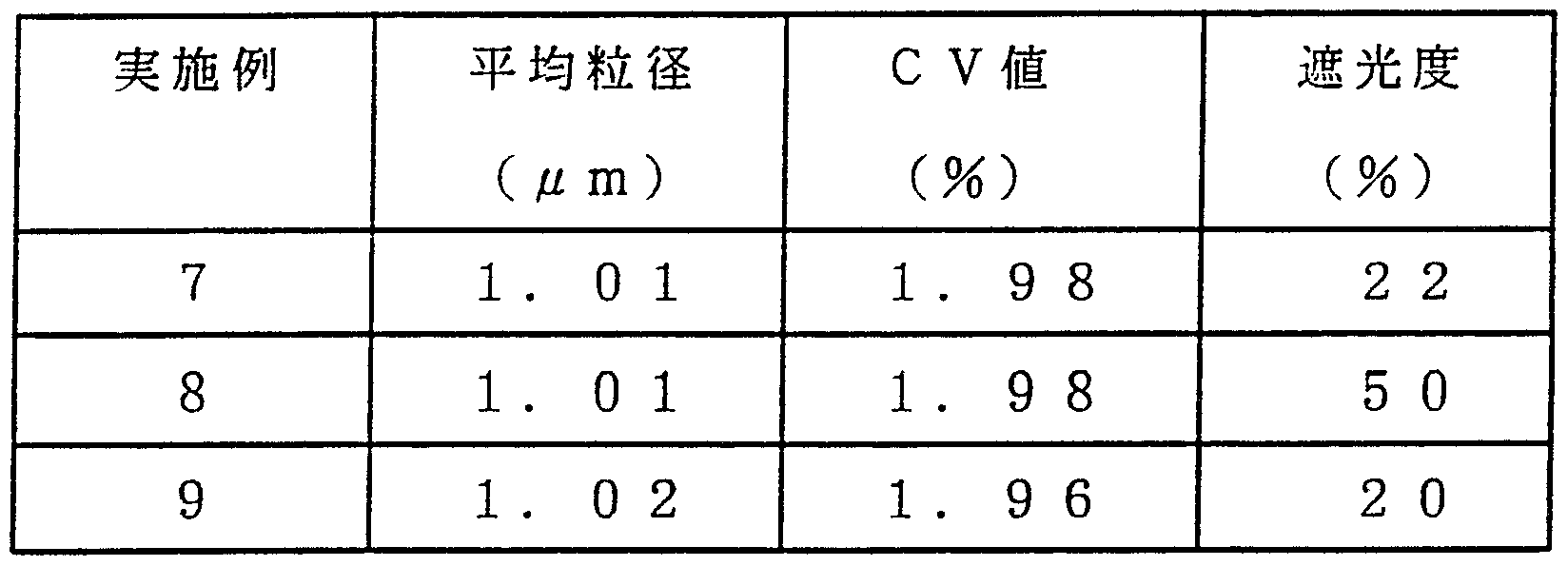
- the average particle size and CV value of the spherical spacer particles obtained as described above were determined in the same manner as in Example 1.
- the light-shielding degree of the particles was determined as follows.
- Each particle is sufficiently dispersed in a 40% by weight aqueous solution of dariserin to obtain a dispersion having a concentration of 1% by weight.
- This dispersion is placed in a quartz cell for transmittance measurement in which the thickness of the transmission layer at the time of measurement is 0.5 imn, and the transmittance is measured with a haze computer.
- the absorbance is proportional to the particle concentration.
- the transmission layer at the time of measurement is entirely Since the absorbance is proportional to the thickness of the permeable layer, the absorbance of the particle diameter d // m is defined as I D , and the transmittance as ⁇ ⁇
- T D was calculated using the above equation, and the degree of light blocking was calculated from this T D using the following equation.
- a liquid crystal display device using the above-mentioned spherical spacer particles as a spacer between display electrodes was prepared as follows, and the characteristics of the prepared display device were evaluated (first, a sealing resin (Mitsui Toatsu Chemical Co., Ltd.) 1 g of each of the spacer particles was dispersed in 100 g of an epoxy resin to prepare an ink composition, and the obtained ink composition was used for a 2 cm ⁇ 2 cm liquid crystal display device.
- a large-sized liquid crystal display device substrate was formed by printing on the periphery of the alignment film of a laminated plate in which a transparent electrode and an alignment film were sequentially formed on a polished glass substrate using a screen printer.
- a large liquid crystal display device was prepared by injecting liquid crystal into the portion of the cell for a large liquid crystal display device obtained in this manner where the sealing resin was not provided> o
- Example 8 The center, right, and left sides of the cell of the liquid crystal display device prepared as described above were cut with a diamond cutter, and the thickness of each was measured with an electron microscope. Table 7 shows the average thickness and the variation (average and standard deviation of the values of three points (center, right side, left side) X 10 sheets).
- Example 8 The center, right, and left sides of the cell of the liquid crystal display device prepared as described above were cut with a diamond cutter, and the thickness of each was measured with an electron microscope. Table 7 shows the average thickness and the variation (average and standard deviation of the values of three points (center, right side, left side) X 10 sheets). Example 8
- the dispersion is dried at a temperature of 110 ° C and then at a temperature of 350 ° C. Heat treatment in an air atmosphere for 3 hours yielded black spherical spacer particles as shown in Table 6.
- Example 7 Using the spherical spacer particles obtained as described above, a display device was manufactured and evaluated in the same manner as in Example 7.
- the dispersion was desolvated at a temperature of 110 to obtain white spherical spacer particles as shown in Table 6.
Landscapes
- Physics & Mathematics (AREA)
- Nonlinear Science (AREA)
- Mathematical Physics (AREA)
- Chemical & Material Sciences (AREA)
- Crystallography & Structural Chemistry (AREA)
- General Physics & Mathematics (AREA)
- Optics & Photonics (AREA)
- Liquid Crystal (AREA)
- Devices For Indicating Variable Information By Combining Individual Elements (AREA)
Description


Claims
Priority Applications (3)
| Application Number | Priority Date | Filing Date | Title |
|---|---|---|---|
| KR1019920701285A KR100260015B1 (ko) | 1990-10-02 | 1991-10-02 | 액정 표시 장치 및 그 제조방법 |
| EP91917330A EP0503098B1 (en) | 1990-10-02 | 1991-10-02 | Liquid crystal display device |
| DE69131902T DE69131902T2 (de) | 1990-10-02 | 1991-10-02 | Flüssigkristall-anzeigevorrichtung |
Applications Claiming Priority (2)
| Application Number | Priority Date | Filing Date | Title |
|---|---|---|---|
| JP26553290 | 1990-10-02 | ||
| JP2/265532 | 1990-10-02 |
Publications (1)
| Publication Number | Publication Date |
|---|---|
| WO1992006403A1 true WO1992006403A1 (fr) | 1992-04-16 |
Family
ID=17418438
Family Applications (1)
| Application Number | Title | Priority Date | Filing Date |
|---|---|---|---|
| PCT/JP1991/001324 Ceased WO1992006403A1 (fr) | 1990-10-02 | 1991-10-02 | Dispositif d'affichage a cristaux liquides |
Country Status (7)
| Country | Link |
|---|---|
| US (1) | US5223964A (ja) |
| EP (1) | EP0503098B1 (ja) |
| KR (1) | KR100260015B1 (ja) |
| DE (1) | DE69131902T2 (ja) |
| ES (1) | ES2141091T3 (ja) |
| SG (1) | SG81196A1 (ja) |
| WO (1) | WO1992006403A1 (ja) |
Families Citing this family (15)
| Publication number | Priority date | Publication date | Assignee | Title |
|---|---|---|---|---|
| JP2596279B2 (ja) * | 1992-01-30 | 1997-04-02 | 双葉電子工業株式会社 | 外囲器の支柱形成方法 |
| JP3197687B2 (ja) * | 1992-08-20 | 2001-08-13 | 積水化学工業株式会社 | 液晶表示装置 |
| JPH06308505A (ja) * | 1993-04-23 | 1994-11-04 | Seiko Instr Inc | 液晶電気光学装置 |
| EP0987581A3 (en) | 1993-12-27 | 2000-07-19 | Matsushita Electric Industrial Co., Ltd. | Liquid-crystal panel, method of manufacturing the same, and liquid-crystal display apparatus |
| US6246456B1 (en) | 1993-12-27 | 2001-06-12 | Matsushita Electric Industrial Co., Ltd. | Liquid-crystal panel of polymer dispersed type, method of manufacturing the same, and liquid-crystal display apparatus |
| SE503136C2 (sv) | 1994-12-09 | 1996-04-01 | Emt Ag | Trycktålig vätskekristallcell |
| JP3347925B2 (ja) * | 1995-09-14 | 2002-11-20 | シャープ株式会社 | 液晶表示素子 |
| US6359667B1 (en) * | 1998-02-09 | 2002-03-19 | Catalysts & Chemicals Industries Co., Ltd. | Organopolysiloxane fine particles, process for the production thereof and liquid crystal displays |
| US6756970B2 (en) * | 1998-11-20 | 2004-06-29 | Microsoft Corporation | Pen-based computer system |
| US6673107B1 (en) * | 1999-12-06 | 2004-01-06 | Advanced Cardiovascular Systems, Inc. | Bifurcated stent and method of making |
| GB0324418D0 (en) * | 2003-10-17 | 2003-11-19 | Bae Systems Plc | Rectroreflective devices and systems |
| CN101040361B (zh) * | 2004-08-17 | 2011-03-30 | 松下电器产业株式会社 | 等离子体显示面板及其制造方法 |
| WO2007063682A1 (ja) * | 2005-11-29 | 2007-06-07 | Konica Minolta Medical & Graphic, Inc. | 平版印刷版材料及び印刷方法 |
| US8919714B2 (en) | 2010-10-13 | 2014-12-30 | Re2, Inc. | Compliant tool holder |
| CN110471224A (zh) * | 2019-08-27 | 2019-11-19 | 业成科技(成都)有限公司 | 曲面式组合模组及其制作方法 |
Citations (6)
| Publication number | Priority date | Publication date | Assignee | Title |
|---|---|---|---|---|
| JPS62269933A (ja) * | 1986-05-19 | 1987-11-24 | Toray Ind Inc | 液晶表示板用スペ−サ |
| JPS62278535A (ja) * | 1986-05-27 | 1987-12-03 | Toray Ind Inc | 粉末組成物 |
| JPS6373225A (ja) * | 1986-09-17 | 1988-04-02 | Catalysts & Chem Ind Co Ltd | 表示装置 |
| JPS6394224A (ja) * | 1986-10-09 | 1988-04-25 | Catalysts & Chem Ind Co Ltd | 表示装置用スペ−サ粒子およびその製造方法 |
| JPH01234826A (ja) * | 1988-03-15 | 1989-09-20 | Showa Denko Kk | 液晶表示素子 |
| JPH0292810A (ja) * | 1988-09-29 | 1990-04-03 | Catalysts & Chem Ind Co Ltd | 球状酸化物粒子の製造方法 |
Family Cites Families (15)
| Publication number | Priority date | Publication date | Assignee | Title |
|---|---|---|---|---|
| JPS6094135A (ja) * | 1983-10-28 | 1985-05-27 | Kinmon Seisakusho:Kk | セラミツク超微粉末の製造法 |
| DE3616133A1 (de) * | 1985-09-25 | 1987-11-19 | Merck Patent Gmbh | Kugelfoermige sio(pfeil abwaerts)2(pfeil abwaerts)-partikel |
| JPS62275005A (ja) * | 1986-02-12 | 1987-11-30 | Catalysts & Chem Ind Co Ltd | 単分散された粒子の製造方法 |
| EP0234816B1 (en) * | 1986-02-12 | 1993-08-11 | Catalysts & Chemicals Industries Co., Ltd. | Processes for preparing mono-dispersed particles |
| JPS6389408A (ja) * | 1986-10-02 | 1988-04-20 | Catalysts & Chem Ind Co Ltd | 黒色系粒子の製造方法 |
| JPS62207709A (ja) * | 1986-03-10 | 1987-09-12 | Seiko Epson Corp | シリカ球の製造方法 |
| JPS63284231A (ja) * | 1987-05-15 | 1988-11-21 | Teijin Ltd | 二軸配向ポリエステルフイルム |
| US5044733A (en) * | 1987-08-19 | 1991-09-03 | Ricoh Company, Ltd. | Super twisted nematic liquid crystal display device having the standard deviation of the spherical grains being not more than 3% and the dispersion quantity of the spherical grains being 100-200 grains/mm2 |
| JPS6478227A (en) * | 1987-09-18 | 1989-03-23 | Ricoh Kk | Liquid crystal display element |
| US5029985A (en) * | 1988-05-19 | 1991-07-09 | Ricoh Company, Ltd. | Multilayer liquid crystal display device |
| JP2673251B2 (ja) * | 1988-06-07 | 1997-11-05 | 株式会社サンノハシ | ステップ金具の製造方法 |
| JPH0280155A (ja) * | 1988-09-14 | 1990-03-20 | Aisin Takaoka Ltd | 鋳枠 |
| JPH02122403A (ja) * | 1988-10-31 | 1990-05-10 | Mitsumi Electric Co Ltd | 回転ヘッド型磁気記録再生装置 |
| JP2724200B2 (ja) * | 1989-03-30 | 1998-03-09 | 宇部日東化成株式会社 | シリカ微粒子の製造方法 |
| JPH0643502A (ja) * | 1992-07-23 | 1994-02-18 | Nippon Sheet Glass Co Ltd | 全固体調光装置およびそれを用いた調光方法 |
-
1991
- 1991-10-02 US US07/852,254 patent/US5223964A/en not_active Expired - Lifetime
- 1991-10-02 EP EP91917330A patent/EP0503098B1/en not_active Expired - Lifetime
- 1991-10-02 ES ES91917330T patent/ES2141091T3/es not_active Expired - Lifetime
- 1991-10-02 DE DE69131902T patent/DE69131902T2/de not_active Expired - Lifetime
- 1991-10-02 WO PCT/JP1991/001324 patent/WO1992006403A1/ja not_active Ceased
- 1991-10-02 KR KR1019920701285A patent/KR100260015B1/ko not_active Expired - Lifetime
- 1991-10-02 SG SG9608020A patent/SG81196A1/en unknown
Patent Citations (6)
| Publication number | Priority date | Publication date | Assignee | Title |
|---|---|---|---|---|
| JPS62269933A (ja) * | 1986-05-19 | 1987-11-24 | Toray Ind Inc | 液晶表示板用スペ−サ |
| JPS62278535A (ja) * | 1986-05-27 | 1987-12-03 | Toray Ind Inc | 粉末組成物 |
| JPS6373225A (ja) * | 1986-09-17 | 1988-04-02 | Catalysts & Chem Ind Co Ltd | 表示装置 |
| JPS6394224A (ja) * | 1986-10-09 | 1988-04-25 | Catalysts & Chem Ind Co Ltd | 表示装置用スペ−サ粒子およびその製造方法 |
| JPH01234826A (ja) * | 1988-03-15 | 1989-09-20 | Showa Denko Kk | 液晶表示素子 |
| JPH0292810A (ja) * | 1988-09-29 | 1990-04-03 | Catalysts & Chem Ind Co Ltd | 球状酸化物粒子の製造方法 |
Non-Patent Citations (1)
| Title |
|---|
| See also references of EP0503098A4 * |
Also Published As
| Publication number | Publication date |
|---|---|
| KR100260015B1 (ko) | 2000-06-15 |
| EP0503098B1 (en) | 2000-01-12 |
| DE69131902D1 (de) | 2000-02-17 |
| US5223964A (en) | 1993-06-29 |
| ES2141091T3 (es) | 2000-03-16 |
| SG81196A1 (en) | 2001-06-19 |
| EP0503098A1 (en) | 1992-09-16 |
| DE69131902T2 (de) | 2000-08-17 |
| EP0503098A4 (en) | 1993-06-30 |
| KR920704187A (ko) | 1992-12-19 |
Similar Documents
| Publication | Publication Date | Title |
|---|---|---|
| WO1992006403A1 (fr) | Dispositif d'affichage a cristaux liquides | |
| JP2000169133A (ja) | シリカ−フッ化マグネシウム水和物複合ゾル及びその製造法 | |
| KR20010101133A (ko) | 경질 코팅물질 및 이를 포함하는 막 | |
| US12209187B2 (en) | Amorphous silica-titania composite oxide powder, resin composition, liquid dispersion, and method for producing silica-coated silica-titania composite oxide powder | |
| EP0234816B1 (en) | Processes for preparing mono-dispersed particles | |
| US8034846B2 (en) | Method for producing modified zirconium oxide-tin oxide composite sol | |
| CN104918897B (zh) | 碱金属阻挡层形成用涂布液及物品 | |
| JP2005186435A (ja) | ハードコート膜付基材および該ハードコート膜形成用塗布液 | |
| JP3824766B2 (ja) | オルガノポリシロキサン微粒子、その製造方法および液晶表示装置 | |
| JP2698541B2 (ja) | 液晶表示板用スペーサーおよびこれを用いた液晶表示板 | |
| JP2005139026A (ja) | 鎖状酸化アンチモン微粒子、該微粒子分散液の製造方法および用途 | |
| JP3524008B2 (ja) | ポリオルガノシロキサン被覆弾性微粒子の製造方法および液晶表示装置 | |
| JP2854134B2 (ja) | 液晶表示装置 | |
| CN101101400A (zh) | 液晶显示盒 | |
| JP2010163588A (ja) | 液晶組成物 | |
| JP3824767B2 (ja) | オルガノポリシロキサン微粒子、その製造方法および液晶表示装置 | |
| JPH06299091A (ja) | 反射防止膜形成用コーティング組成物 | |
| JPWO1992006403A1 (ja) | 液晶表示装置 | |
| JP3315110B2 (ja) | 球状スペーサ粒子およびこれを用いた表示装置 | |
| JPH0352047B2 (ja) | ||
| JP4033620B2 (ja) | スペーサ粒子および該スペーサ粒子を用いた液晶表示装置 | |
| JPH0782173B2 (ja) | 表示装置用スペーサ粒子の製造方法 | |
| JPH0782172B2 (ja) | 黒色系粒子およびこの黒色系粒子を含む表示装置 | |
| JPH0553122A (ja) | スペーサー粒子およびこれを含む液晶表示装置 | |
| JP2628984B2 (ja) | 表示装置用スペーサ粒子の製造方法 |
Legal Events
| Date | Code | Title | Description |
|---|---|---|---|
| AK | Designated states |
Kind code of ref document: A1 Designated state(s): JP KR US |
|
| AL | Designated countries for regional patents |
Kind code of ref document: A1 Designated state(s): DE ES FR GB IT NL SE |
|
| WWE | Wipo information: entry into national phase |
Ref document number: 1991917330 Country of ref document: EP |
|
| WWE | Wipo information: entry into national phase |
Ref document number: 1019920701285 Country of ref document: KR |
|
| WWP | Wipo information: published in national office |
Ref document number: 1991917330 Country of ref document: EP |
|
| WWG | Wipo information: grant in national office |
Ref document number: 1991917330 Country of ref document: EP |