WO1999017238A1 - Reduktionsverfahren für simulationen zur wissensdatenerzeugung - Google Patents
Reduktionsverfahren für simulationen zur wissensdatenerzeugung Download PDFInfo
- Publication number
- WO1999017238A1 WO1999017238A1 PCT/EP1998/005325 EP9805325W WO9917238A1 WO 1999017238 A1 WO1999017238 A1 WO 1999017238A1 EP 9805325 W EP9805325 W EP 9805325W WO 9917238 A1 WO9917238 A1 WO 9917238A1
- Authority
- WO
- WIPO (PCT)
- Prior art keywords
- components
- basic
- knowledge data
- states
- building blocks
- Prior art date
- Legal status (The legal status is an assumption and is not a legal conclusion. Google has not performed a legal analysis and makes no representation as to the accuracy of the status listed.)
- Ceased
Links
Classifications
-
- G—PHYSICS
- G06—COMPUTING OR CALCULATING; COUNTING
- G06F—ELECTRIC DIGITAL DATA PROCESSING
- G06F30/00—Computer-aided design [CAD]
- G06F30/30—Circuit design
- G06F30/36—Circuit design at the analogue level
- G06F30/367—Design verification, e.g. using simulation, simulation program with integrated circuit emphasis [SPICE], direct methods or relaxation methods
Definitions
- the invention relates to a method for reducing the number of simulation steps required in a simulation method for computer-controlled generation of knowledge data about an overall system consisting of several electrically controllable components. Furthermore, the invention relates to a computer for carrying out a reduction process.
- US Pat. No. 5,625,578 describes a control method for simulations which are used to investigate the electromagnetic behavior of electrical components of a printed circuit board.
- the simulations are based on a model equivalent to the circuit pattern of the circuit card.
- the number of equivalent lent circuit components is reduced by four orders of magnitude without incurring losses in terms of the accuracy of the equivalence model.
- the circuit pattern is represented by geometric elements.
- groups of main elements are compiled that contain only those selected elements whose distance from the neighboring elements exceeds a defined minimum wavelength ⁇ .
- field values are assigned to the selected elements.
- the field values of the elements not taken into account are defined via the field values of the selected elements, and a matrix representing the equivalence model is generated using a ranking method that takes into account the number of selected elements.
- the object of the invention is to provide a reduction method for simulations for the generation of knowledge data, which considerably reduces the number of simulation steps required, without ignoring information relevant for the generation of knowledge data.
- the method reduces the number of simulation steps required in simulation methods that are used for the computer-controlled generation of knowledge data about complete systems, which consist of several electrically controllable components.
- the electrically controllable components are broken down into components that comprise one or more basic components.
- the electrical connections between the basic components and between the components are then recorded, discrete electrical status values are assigned to the basic components, and operating statuses and possible component statuses of the individual components are defined in relation to the electrical status values of the basic components belonging to a component.
- the sizes necessary for the generation of knowledge data and measurable on the basic building blocks and components are determined and those basic building blocks are determined which have no influence on the defined measurable sizes.
- the basic elements without influence are summarized and eliminated.
- the D ⁇ S process can be used for many different simulation processes that are used for the computer-controlled generation of knowledge data about an overall system consisting of several electrically controllable components.
- the division of knowledge data into knowledge data types enables the selection of one or more knowledge data types that are relevant to a specific question. This is advantageous because the quantities that can be measured on the basic building blocks and components are only to be specified for the selected knowledge data types and the number of simulation steps required is reduced again.
- Fig.4 shows the relationship between the basic building blocks and the components
- Figure 7 illustrates the work of binding operators
- FIG. 8 shows an extract from a relation table. The sequence of the method for reducing the number of simulation steps is shown in FIG. 1 Represent procedure.
- the main components that occur in the periphery of automation devices are, as summarized in the table in FIG. 3, resistors, switches, lines, connectors, lamps, bundles of cables, sensors, relays, fuses, solenoid valves, motors and signal transmitters.
- Some of the components can be summarized in aggregate A.
- the aggregate information with the structure relationships is usually available in a data processing form. This information is already available during the product development phases e.g. present in CAD systems or can be derived from model-based programs.
- An aggregate A is a set of components C. with a local arrangement.
- An aggregate describes a smallest exchangeable unit.
- the individual units A are connected to one another by the pins Pl, the components C j .
- An aggregate A consists of zero or more components C j .
- a component C j belongs exactly to an aggregate A ,.
- An electrical component C j has zero or more ports PO k .
- a port PO k is part of a component C j .
- Each port PO k can contain one or more pins Pl m .
- Each pin PI m is assigned to exactly one port PO k .
- a connection CH refers to two pins Pl m .
- a pin Pl m can be related to none or a connection CNi.
- Nonlinear components such as Diodes are replaced by processor-controlled automation devices.
- the software functions simulate the non-linear behavior and, on the other hand, the non-linear components are integrated into the automation devices, so that the behavior can be described linearly outside the systems within the framework of the relevant information.
- Dynamic properties of the components considered here play a subordinate role, since the dynamic behavior properties of the components considered do not provide a significantly higher information gain.
- Each basic building block U refers to a component C ,.
- the basic building blocks or atomic units differ depending on the type in active and passive basic building blocks.
- the active basic components are divided into current sources Ql and voltage sources QV, whereas the passive basic components contain simple resistors R k .
- the type of the basic module is characterized by type (U.
- the basic module U j can assume different discrete values V k depending on the state of the component.
- the individual discrete values V k of component C are related to one another by the states of the components via a behavior description B k coupled
- the passive basic building blocks are considered in the further considerations.
- the active building blocks are listed for completion.
- the behavior of the components is characterized by discrete states. As shown in Fig. 4, this results in discrete values for the basic building blocks, which represent different electrical states of the components.
- the individual discrete states of the basic building blocks have a specific relationship to the component states, which include the standard behavior and the fault behavior of a component. In addition, it can be used for many applications such.
- Electrical and non-electrical operating states can be distinguished depending on the type of physical quantity that causes the operating state change. The electrical operating states are directly influenced by electrical quantities of the basic modules to be examined
- Each component C can assume different operating states O. Depending on the influencing factor, the operating state transitions depend on electrical and / or non-electrical events and variables. If there are several operating states, the state transition is primarily either electrical or non-electrical result. The non-electrical operating states ONE can be achieved, for example, by mechanical influences. A component C can assume electrical operating states OE if an electrical effect causes an operating state change. A change between the operating states can be carried out as often as required without restriction.
- Each component has at least two component states F m , which are not changed by electrical variables or by external influences in normal operation.
- the component states F m hide at least one faulty state and the normal state. It is therefore of primary importance for simulation processes for the generation of diagnostic knowledge to recognize the component state.
- a component state change from the normal state to an error state occurs only once. The sporadic errors are an exception.
- An incandescent lamp e.g. can be defective or not defective regardless of the operating voltage. This behavior, which is permanently assigned to the component, is the component state. In the component state not defective, different operating states are possible, depending on the electrical quantities available. In general, a distinction between active mode (the lamp is on) and passive mode (the lamp is off) is sufficient.
- the individual components can be assigned to the complete overall system or the periphery of the overall system.
- the complete system as a whole can be included in the model, but the information of interest can mainly be found in the periphery.
- the periphery of the overall system can be modeled as a graph, in which the basic building blocks represent the edges. To connect the basic building blocks, connection points are required that appear as nodes in the graph.
- a graph G is given by a set of nodes N and edges E. Each node N, is the junction of two or more edges E r An edge E, connects two nodes N, and N r The graph G is called undirected if there is no node order an edge exists.
- the graph elements GE include both the edges E and the nodes N,
- the degree or degree (NJ of the node is determined by the number of edges E, at this node.
- the edges E j connected to the node N are characterized by the edges (N,).
- N r N, The result of the chain (N r N,) function is a set of edges E “die directly in a chain mix the elements N, and N j .
- Each inner knot of a chain that is not closed has a knot grade 2, the outer knots have a knot grade 3 or larger.
- a graph has the following properties:
- the graph is represented by the edges E; with the atomic units U, and the nodes N j .
- a node N is the connection point of two or more basic building blocks U.
- the entire behavior of the electrical periphery is characterized by the elementary peripheral graph G ep .
- the node potentials P t or the currents l j can be measured by a basic building block.
- the measurability of the node potential P; or the branch current I depend on the local position and the structure of the entire system and can assume the values measurable or not measurable.
- the potential P, at the node N also contains a fixed value V fi or an unknown value V vi .
- branch currents I fixed or unknown values result analogously.
- the measurability of a physical quantity can be clearly assigned to a basic building block U, or a node N.
- the periphery can thus be represented as an undirected graph.
- the relationships shown in FIG. 2 result between the information which can be extracted from, for example, CAD data and which describes the structure and the individual components and the states of the individual components.
- At least one component state F m can be assigned to each component C-.
- Each component state F m belongs to one component C ,.
- the operating state O is exactly one component Cj. assigned.
- a component C can contain one or more operating states O.
- the operating state O can be clearly caused by measurable quantities.
- At least one node belongs to each component C j .
- a graph reduction can be carried out which contains the essential behavioral properties with regard to the observable physical quantities.
- a reduction graph G r can consist of several subgraphs. These include the elementary peripheral graph G ep , several intermediate graphs G t and a head graph G h . The nodes and edges of the individual subgraphs are connected to each other and represent the reduction rule.
- the basic operations known from network analysis are used to construct the reduction graph.
- the basic consideration is that under certain conditions branches in an electrical network can be represented by an equivalent branch of a simpler structure.
- the efficient construction of a reduction graph requires equivalency operation. in which the network structure is converted into an equivalent form of representation and this ultimately forms the starting point for a further reduction step.
- the equivalence operations do not reduce the network structure, ie the number of components in the parent graph does not change compared to that of the current graph
- the series reduction is applicable to basic modules of the type resistors R ⁇ and voltage sources Q v .
- n-beam resistance star complete n-corner The applicability of the stem polygon reduction is limited to resistors R. In general, the following applies to the calculation of the corner resistance value:
- the reduced Teiigraph comprises n (n-1) / 2 edges and u-1 nodes. This leads to a reduction effort for adding and removing edges in the order of magnitude O (n 2 ).
- the stem polygon reduction can be carried out according to a sorted list in which the higher order nodes are processed first. However, the practical effects on the reduced graph are not significant, since the order on the stem polygon reduction only changes the shape of the reduction graph, but not the header graph. Voltage source reduction:
- the aim of the equivalence operation for voltage sources and resistors is to sort the individual basic modules according to their type and to prepare them for a subsequent series reduction.
- the values of the individual graph elements GE represent operating and component states.
- the primary goal is to determine the component status and from this the system status.
- the set of all system states is thus the permutation of all individual component states, which in turn are represented by the discrete values.
- the overall or partial system state is composed of the permutations of the discrete values Vi of the individual basic components U,. To see the overall behavior of a child graph in the parent To transfer graphs, it is necessary to create the permutations between the individual values.
- the O resistance reduction, loop reduction, voltage source reduction, and current source reduction operations remove graph elements without adding new elements. No special procedures are necessary for these operations.
- the operations series, parallel and stem polygon reduction insert new values in the graph, so that the creation of the permutations and the corresponding processing is necessary.
- FIG. 6 shows the basic processing of the individual values in order to generate a reduced partial graph G sub red from any subgraph G sub 0Pg .
- a sequential permutation method is used to calculate the permutations.
- Equations (0.2), (0.5) and (0.10) reduce the number of discrete result values after the reduction operations series, parallel and stem polygon reduction.
- Every stem polygon reduction with a node degree greater than 3 leads to an increase in the number of edges in the graph.
- the stem polygon reduction complements the original component states with further combinations, which are referred to below as pseudo states.
- pseudo states With this reduction, the increase of n (n-1) / 2 edges leads to an exponential growth of the pseudo states. On the one hand, this can lead to a rapid increase in the computation or storage effort from one reduction step to the next.
- the number of states in the overall system increases with each star polygon reduction step.
- binding operator marks all permuted values as a so-called permutation block.
- the calculation of the values in a reduction step is ultimately not based on the individual values, but rather the entire permutation block with all bindings is taken into account in the calculation
- Fig. 7 shows the processing of the binding operations. Despite increasing the elements in a stem polygon reduction, the binding operator prevents pseudo-component states.
- This method of calculating the individual discrete resistance values enables any combinations to be taken into account during the reduction process and other undesired combinations to be excluded from the outset. For example, certain types of knowledge data, such as Single errors can be specified and reduced by this method.
- one or the other behavioral characteristic represented by the individual discrete values, can occur several times. However, it is sufficient to consider only one behavioral characteristic at a time.
- Values that have no binding can be reduced to a single occurrence. In the case of elements with a bond, a combination is sufficient for the further representation of the resistance.
- the reduction in value can take place directly after a reduction operation, but it can also take place only after several reduction steps.
- the network is reduced with the basic operations described. After each reduction run, the number of nodes N, For the number of atomic units U, in the reduced graph, a reduction caused by the stem-polygon reduction is not guaranteed Basic graph G ⁇ is processed until no node or edge can be removed from the graph.
- the head graph consists of nodes with fixed or measurable potentials. All nodes with unknown potentials are removed in the head graph G h . Atomic units U
- Clustering makes it possible to reduce a system-wide problem to the essential elements in the system and thus to limit the global problem to a limited local area.
- a cluster C consists of a certain number of elements. All states of the elements in the cluster only affect sizes and error messages in this local cluster area.
- the individual areas can refer to different levels of abstraction.
- the elementary peripheral graph forms a level of abstraction. Due to the mutual coupling of the individual basic building blocks or atomic units via the corresponding components, there is a second level, which contains Ciuster areas at component level.
- Clustering on the level of the elementary peripheral graph comprises the basic building blocks as elements. In the overall system, every possible observation belongs to a cluster.
- a basic cluster or atomic cluster C a is a coherent path of basic building blocks or atomic units. Each basic building block U, and the nodes H- in between, can be assigned to exactly one basic cluster C a . All values that the atomic units and the nodes assume affect only the sizes in the basic cluster C " a a.
- the related components can be recognized with any graph 1 transfer method.
- each node and edge traversed must be entered in a list and marked as processed.
- the result of clustering at the atomic level is a list of clusters, each of which contains references to the individual basic building blocks and the neighboring nodes that belong to these clusters.
- a complex elementary peripheral graph is broken down into spatially limited areas of knowledge data.
- the graph elements in a cluster have no atomic-level relationships with graph elements in another cluster. Each cluster thus forms a completed subproject and can therefore also be described as a focus area.
- Clustering also offers the possibility of creating the reduction graph in parallel for the overall system. In the best case scenario, all clusters can be processed in parallel. Under these conditions, the time complexity of O (n 12 ) arises for the creation of the reduction graph with n 'local graph elements.
- Individual components can have a relationship to several basic building blocks.
- the states of the components also relate to one or more basic modules. This creates relations between basic building blocks of different basic clusters.
- a component-oriented cluster C c comprises one or more basic clusters C E with its basic building blocks U f and nodes Nj.
- the basic clusters C a are connected to one another by the relationships between the components and the basic building blocks. However, only the components in the periphery are taken into account.
- the same creation procedures apply for the component-oriented cluster as for the basic clusters.
- the result of clustering at component level is a list of clusters, each with references to the basic clusters and references to components.
- the component-oriented clusters form the basis for the relationships between the basic components in the header graph and the states of the components.
- a table of relations provides the necessary information.
- For every component-oriented Cluster describes a relation table of all possible component states of the cluster with the corresponding discrete values of the basic building blocks. The table can also be limited to selected combinations of component states. This table is continuously updated throughout the reduction process. At the end of the reduction process, the table shows the component states specified at the beginning with the discrete values of the header graph.
- F ⁇ g.8 illustrates an extract from a table of relations.
- the associated component states can be determined relatively easily from a known graph using the header graph. If the simulation result is added after the last column of the relation table, the result is e.g. the classic error table with the component states and the corresponding system sizes when generating diagnostic knowledge.
- the size of the table can be limited to certain combinations.
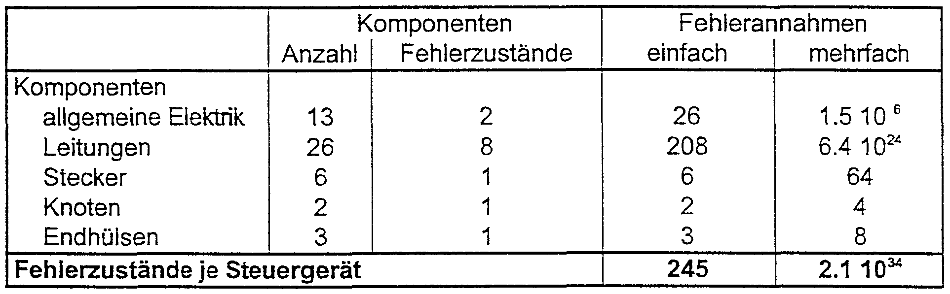
- An example of a diagnosis system for a complete vehicle system is to estimate the necessary simulations without and with the reduction method. For the sake of completeness, single and multiple errors are shown for the possible error assumptions. First, the error states are considered. Then the controls are discussed, since they play an important role in the error effect and diagnosis.
Landscapes
- Engineering & Computer Science (AREA)
- Computer Hardware Design (AREA)
- Physics & Mathematics (AREA)
- Theoretical Computer Science (AREA)
- Microelectronics & Electronic Packaging (AREA)
- Evolutionary Computation (AREA)
- Geometry (AREA)
- General Engineering & Computer Science (AREA)
- General Physics & Mathematics (AREA)
- Management, Administration, Business Operations System, And Electronic Commerce (AREA)
Abstract
Description




Claims
Priority Applications (2)
| Application Number | Priority Date | Filing Date | Title |
|---|---|---|---|
| JP2000514232A JP3439741B2 (ja) | 1997-09-26 | 1998-08-21 | 知識データ生成シミュレーションのための整理編集(減少)方法 |
| EP98948855A EP1018087A1 (de) | 1997-09-26 | 1998-08-21 | Reduktionsverfahren für simulationen zur wissensdatenerzeugung |
Applications Claiming Priority (2)
| Application Number | Priority Date | Filing Date | Title |
|---|---|---|---|
| DE19742450.3 | 1997-09-26 | ||
| DE19742450A DE19742450A1 (de) | 1997-09-26 | 1997-09-26 | Reduktionsverfahren für Simulationen zur Wissensdatenerzeugung |
Publications (2)
| Publication Number | Publication Date |
|---|---|
| WO1999017238A1 true WO1999017238A1 (de) | 1999-04-08 |
| WO1999017238A9 WO1999017238A9 (de) | 1999-06-17 |
Family
ID=7843662
Family Applications (1)
| Application Number | Title | Priority Date | Filing Date |
|---|---|---|---|
| PCT/EP1998/005325 Ceased WO1999017238A1 (de) | 1997-09-26 | 1998-08-21 | Reduktionsverfahren für simulationen zur wissensdatenerzeugung |
Country Status (4)
| Country | Link |
|---|---|
| EP (1) | EP1018087A1 (de) |
| JP (1) | JP3439741B2 (de) |
| DE (1) | DE19742450A1 (de) |
| WO (1) | WO1999017238A1 (de) |
Cited By (1)
| Publication number | Priority date | Publication date | Assignee | Title |
|---|---|---|---|---|
| US7418375B2 (en) | 2003-07-04 | 2008-08-26 | Yazaki Corporation | Load current evaluation device, load current evaluation method, and recording medium containing load current evaluation program |
Families Citing this family (2)
| Publication number | Priority date | Publication date | Assignee | Title |
|---|---|---|---|---|
| DE10310422A1 (de) | 2003-03-11 | 2004-09-23 | Zf Friedrichshafen Ag | Verfahren zur Vernetzung von Regelungs- und/oder Steuerungsfunktionen für ein Kraftfahrzeug |
| DE102004019151A1 (de) * | 2004-04-21 | 2005-11-10 | Daimlerchrysler Ag | Rechnergestütztes Diagnosesystem auf der Basis von Heuristiken und System-Topologien |
-
1997
- 1997-09-26 DE DE19742450A patent/DE19742450A1/de not_active Ceased
-
1998
- 1998-08-21 EP EP98948855A patent/EP1018087A1/de not_active Withdrawn
- 1998-08-21 JP JP2000514232A patent/JP3439741B2/ja not_active Expired - Fee Related
- 1998-08-21 WO PCT/EP1998/005325 patent/WO1999017238A1/de not_active Ceased
Non-Patent Citations (4)
| Title |
|---|
| HEINZELMANN A ET AL: "Model-based fault simulation: a reduction method for the diagnosis of electrical components", METHODOLOGY AND TOOLS IN KNOWLEDGE-BASED SYSTEMS. 11TH INTERNATIONAL CONFERENCE ON INDUSTRIAL AND ENGINEERING APPLICATIONS OF ARTIFICIAL INTELLIGENCE AND EXPERT SYSTEMS. IEA-98-AIE. PROCEEDINGS, METHODOLOGY AND TOOLS IN KNOWLEDGE-BASED SYSTEMS 11TH I, ISBN 3-540-64582-9, 1998, Berlin, Germany, Springer-Verlag, Germany, pages 840 - 847 vol.1, XP002092751 * |
| MAUSS J ET AL: "Diagnosis by algebraic modeling and fault-tree induction", DX-95: 6TH INTERNATIONAL WORKSHOP ON PRINCIPLES OF DIAGNOSIS, pages 73-80, XP002092752 * |
| MAUSS J ET AL: "Qualitative reasoning about electrical circuits using series-parallel-star trees", 10TH INTERNATIONAL WORKSHOP ON QUALITATIVE REASONING, 1996, pages 147 - 153, XP002092753 * |
| SEIBOLD W: "First time right from layout to repair electrical system CAD", 30TH INTERNATIONAL SYMPOSIUM ON AUTOMOTIVE TECHNOLOGY AND AUTOMATION. MECHATRONICS/AUTOMOTIVE ELECTRONICS. REAL WORLD REASONS TO USE UNIGRAPHICS AND IMAN, PROCEEDINGS OF INTERNATIONAL SYMPOSIUM ON AUTOMOTIVE TECHNOLOGY AND AUTOMATION, FLORENCE, ITALY, ISBN 0-947719-87-3, 1997, Croydon, UK, Automotive Autom, UK, pages 483 - 492 vol.1, XP002092754 * |
Cited By (1)
| Publication number | Priority date | Publication date | Assignee | Title |
|---|---|---|---|---|
| US7418375B2 (en) | 2003-07-04 | 2008-08-26 | Yazaki Corporation | Load current evaluation device, load current evaluation method, and recording medium containing load current evaluation program |
Also Published As
| Publication number | Publication date |
|---|---|
| JP3439741B2 (ja) | 2003-08-25 |
| EP1018087A1 (de) | 2000-07-12 |
| JP2001518671A (ja) | 2001-10-16 |
| WO1999017238A9 (de) | 1999-06-17 |
| DE19742450A1 (de) | 1999-04-08 |
Similar Documents
| Publication | Publication Date | Title |
|---|---|---|
| DE3787431T2 (de) | Verfahren zur Generierung einer Kandidatenliste von fehlerhaften Schaltungselementen und Verfahren zur Isolierung von Fehlern in einer logischen Schaltung unter Verwendung dieser Kandidatenliste. | |
| EP2801873B1 (de) | Testeinrichtung zum Test eines virtuellen Steuergeräts | |
| DE102007042752B4 (de) | Verfahren zur Analyse der Zuverlässigkeit technischer Anlagen mit Hilfe von physikalischen Modellen | |
| DE69225527T2 (de) | Verfahren und System zur automatischen Bestimmung der logischen Funktion einer Schaltung | |
| EP0715266A2 (de) | Verfahren zur Initialisierung und Aktualisierung eines Netzmodells | |
| DE3685711T2 (de) | Anordnung zur simulation von rechnerfunktionen von grossrechenanlagen. | |
| EP0966703B1 (de) | Verfahren zur rechnergestützten fehleranalyse von sensoren und/oder aktoren in einem technischen system | |
| DE19536203A1 (de) | Fehlerdiagnoseverfahren für eine sequentielle Schaltung | |
| EP0580663B1 (de) | Verfahren zur verifikation datenverarbeitender systeme | |
| DE102016102920A1 (de) | Verfahren zur Konfiguration eines zum Testen eines elektronischen Steuergeräts eingerichteten Testgeräts | |
| WO1997015877A2 (de) | Computergestütztes arbeits- und informationssystem und zugehöriger baustein | |
| DE3854636T2 (de) | Automatischer Prüfprozess für logische Geräte. | |
| DE102004019151A1 (de) | Rechnergestütztes Diagnosesystem auf der Basis von Heuristiken und System-Topologien | |
| DE19742448C1 (de) | Diagnosemodul zum Erstellen einer Diagnose für elektrisch ansteuerbare Systeme und Diagnoseeinrichtung zum Erstellen einer Gesamtsystemdiagnose | |
| EP1018087A1 (de) | Reduktionsverfahren für simulationen zur wissensdatenerzeugung | |
| DE10133670A1 (de) | Verfahren zur automatischen Erzeugung einer Wissensbasis für ein Diagnosesystem | |
| DE19924242C2 (de) | Vektorrestauration mit beschleunigter Validation und Verfeinerung | |
| DE3688437T2 (de) | Verfahren zur Umwandlung einer MOS-Schaltung von Schaltebenedarstellung in eine boolesche Darstellung und Verfahren zur Fehlersimulation in einer auf der Schaltebene dargestellten MOS-Schaltung durch das Verwenden seiner booleschen Darstellung. | |
| DE10150914C1 (de) | Verfahren zur strukturellen Analyse und Korrektur eines mittels einer Computersprache beschriebenen Differentialgleichungssystems | |
| EP1068580B1 (de) | Verfahren zum vergleich elektrischer schaltungen | |
| DE10125610A1 (de) | Verfahren und Computersystem zur Durchführung einer Simulation | |
| DE102017130842A1 (de) | Konfigurationssystem zur Konfiguration eines zum Testen eines elektronischen Steuergeräts geeigneten Testsystems | |
| EP1390883A2 (de) | Verfahren zum bereitstellen von fehlerinformationen über inkonsistenzen in einem system von differentialgleichungen | |
| DE10343344B4 (de) | Verfahren zum Prüfen einer elektrischen Schaltung | |
| DE19710463C2 (de) | Verfahren zur automatischen Differentiation auf einem Rechner insbesondere zur Simulation elektronischer Schaltungen |
Legal Events
| Date | Code | Title | Description |
|---|---|---|---|
| AK | Designated states |
Kind code of ref document: A1 Designated state(s): JP US |
|
| AL | Designated countries for regional patents |
Kind code of ref document: A1 Designated state(s): AT BE CH CY DE DK ES FI FR GB GR IE IT LU MC NL PT SE |
|
| DFPE | Request for preliminary examination filed prior to expiration of 19th month from priority date (pct application filed before 20040101) | ||
| 121 | Ep: the epo has been informed by wipo that ep was designated in this application | ||
| AK | Designated states |
Kind code of ref document: C2 Designated state(s): JP US |
|
| AL | Designated countries for regional patents |
Kind code of ref document: C2 Designated state(s): AT BE CH CY DE DK ES FI FR GB GR IE IT LU MC NL PT SE |
|
| COP | Corrected version of pamphlet |
Free format text: PAGES 3 AND 8-11, DESCRIPTION, REPLACED BY NEW PAGES 3, 3A AND 8-11; PAGES 10/12-12/12, DRAWINGS, ADDED; PAGES 1/9-9/9, DRAWINGS, RENUMBERED AS PAGES 1/12-9/12; AFTER RECTIFICATION OF OBVIOUS ERRORS AS AUTHORIZED BY THE INTERNATIONAL SEARCHING AUTHORITY |
|
| WWE | Wipo information: entry into national phase |
Ref document number: 1998948855 Country of ref document: EP |
|
| WWE | Wipo information: entry into national phase |
Ref document number: 09509404 Country of ref document: US |
|
| WWP | Wipo information: published in national office |
Ref document number: 1998948855 Country of ref document: EP |
|
| WWW | Wipo information: withdrawn in national office |
Ref document number: 1998948855 Country of ref document: EP |