WO2000023829A1 - Optical filter - Google Patents
Optical filter Download PDFInfo
- Publication number
- WO2000023829A1 WO2000023829A1 PCT/JP1999/005785 JP9905785W WO0023829A1 WO 2000023829 A1 WO2000023829 A1 WO 2000023829A1 JP 9905785 W JP9905785 W JP 9905785W WO 0023829 A1 WO0023829 A1 WO 0023829A1
- Authority
- WO
- WIPO (PCT)
- Prior art keywords
- group
- dye
- layer
- optical filter
- ring
- Prior art date
- Legal status (The legal status is an assumption and is not a legal conclusion. Google has not performed a legal analysis and makes no representation as to the accuracy of the status listed.)
- Ceased
Links
Classifications
-
- C—CHEMISTRY; METALLURGY
- C09—DYES; PAINTS; POLISHES; NATURAL RESINS; ADHESIVES; COMPOSITIONS NOT OTHERWISE PROVIDED FOR; APPLICATIONS OF MATERIALS NOT OTHERWISE PROVIDED FOR
- C09B—ORGANIC DYES OR CLOSELY-RELATED COMPOUNDS FOR PRODUCING DYES, e.g. PIGMENTS; MORDANTS; LAKES
- C09B23/00—Methine or polymethine dyes, e.g. cyanine dyes
- C09B23/02—Methine or polymethine dyes, e.g. cyanine dyes the polymethine chain containing an odd number of >CH- or >C[alkyl]- groups
- C09B23/06—Methine or polymethine dyes, e.g. cyanine dyes the polymethine chain containing an odd number of >CH- or >C[alkyl]- groups three >CH- groups, e.g. carbocyanines
-
- G—PHYSICS
- G02—OPTICS
- G02B—OPTICAL ELEMENTS, SYSTEMS OR APPARATUS
- G02B1/00—Optical elements characterised by the material of which they are made; Optical coatings for optical elements
- G02B1/10—Optical coatings produced by application to, or surface treatment of, optical elements
- G02B1/11—Anti-reflection coatings
-
- G—PHYSICS
- G02—OPTICS
- G02B—OPTICAL ELEMENTS, SYSTEMS OR APPARATUS
- G02B5/00—Optical elements other than lenses
- G02B5/20—Filters
- G02B5/22—Absorbing filters
- G02B5/223—Absorbing filters containing organic substances, e.g. dyes, inks or pigments
-
- G—PHYSICS
- G02—OPTICS
- G02B—OPTICAL ELEMENTS, SYSTEMS OR APPARATUS
- G02B1/00—Optical elements characterised by the material of which they are made; Optical coatings for optical elements
- G02B1/10—Optical coatings produced by application to, or surface treatment of, optical elements
- G02B1/14—Protective coatings, e.g. hard coatings
-
- G—PHYSICS
- G02—OPTICS
- G02B—OPTICAL ELEMENTS, SYSTEMS OR APPARATUS
- G02B1/00—Optical elements characterised by the material of which they are made; Optical coatings for optical elements
- G02B1/10—Optical coatings produced by application to, or surface treatment of, optical elements
- G02B1/16—Optical coatings produced by application to, or surface treatment of, optical elements having an anti-static effect, e.g. electrically conducting coatings
-
- G—PHYSICS
- G02—OPTICS
- G02B—OPTICAL ELEMENTS, SYSTEMS OR APPARATUS
- G02B1/00—Optical elements characterised by the material of which they are made; Optical coatings for optical elements
- G02B1/10—Optical coatings produced by application to, or surface treatment of, optical elements
- G02B1/18—Coatings for keeping optical surfaces clean, e.g. hydrophobic or photo-catalytic films
-
- G—PHYSICS
- G02—OPTICS
- G02B—OPTICAL ELEMENTS, SYSTEMS OR APPARATUS
- G02B5/00—Optical elements other than lenses
- G02B5/20—Filters
- G02B5/22—Absorbing filters
-
- H—ELECTRICITY
- H01—ELECTRIC ELEMENTS
- H01J—ELECTRIC DISCHARGE TUBES OR DISCHARGE LAMPS
- H01J2211/00—Plasma display panels with alternate current induction of the discharge, e.g. AC-PDPs
- H01J2211/20—Constructional details
- H01J2211/34—Vessels, containers or parts thereof, e.g. substrates
- H01J2211/44—Optical arrangements or shielding arrangements, e.g. filters or lenses
Definitions
- the present invention relates to an optical filter having a transparent support and a filter layer.
- the present invention relates to an image display device such as a liquid crystal display device (LCD), a plasma display panel (PDP), an electroluminescent display (ELD), a cathode ray tube display device (CRT), a fluorescent display tube, and a field emission display.
- the present invention relates to an optical filter which is attached to the surface of a surface for improving color reproduction.
- Image display devices such as liquid crystal display (LCD), plasma display panel (PDP), electorifice luminescence display (ELD), cathode ray tube display (CRT), fluorescent display tube, and field emission display are in principle red.
- LCD liquid crystal display
- PDP plasma display panel
- ELD electorifice luminescence display
- CRT cathode ray tube display
- fluorescent display tube field emission display
- a color image is displayed using a combination of the three primary colors, blue, and green.
- PDP plasma display panel
- extra light wavelength in the range of 560 to 620 nm
- An object of the present invention is to provide an optical filter having an appropriate color correction function.
- Another object of the present invention is to provide a plasma display panel whose color is appropriately corrected.
- the present invention relates to an optical filter in which a transparent support and a filter layer are laminated, wherein the filter layer has an absorption maximum in a wavelength range of 560 to 60 nm, and a half-width of the absorption maximum. Is in the range of 5 to 50 nm.
- the present invention also provides a plasma display panel having a display surface covered with an optical filter, wherein the optical filter has a transparent support and a filter layer, and the filter layer has a wavelength in the range of 560 to 60 nm.
- the present invention also provides a plasma display panel characterized by having an absorption maximum, and having a half width of the absorption maximum in the range of 5 to 50 nm.
- the present inventor has studied an image display device (particularly a plasma display panel), and found that extra light (wavelength in the range of 560 to 60 nm) hindered by light emission from the three primary color phosphors is very sharp. It was found that it had an excellent emission spectrum peak. Therefore, the optical filter for cutting off the extra light needs to have a sharp absorption spectrum peak corresponding to a sharp emission spectrum peak. If the absorption spectrum peak of the optical filter is broad, the light that is involved in image display is cut.
- the optical filter of the present invention has a very sharp absorption spectrum peak in which the half width of the absorption maximum is in the range of 5 to 50 nm, only the light having a wavelength that reduces the color purity of the image is used. Can be selectively cut.
- the optical filter of the present invention has an appropriate color correction function.
- FIG. 1 is a schematic cross-sectional view showing a layer configuration of an optical filter in which one filter and an antireflection layer are provided on the side opposite to a transparent support.
- FIG. 2 is a schematic cross-sectional view showing a layer configuration of an optical filter in which one filter and an antireflection layer are provided on the same side of a transparent support.
- FIG. 1 is a schematic cross-sectional view showing a layer configuration of an optical filter in which a filter layer is provided on a side opposite to a transparent support from an antireflection layer.
- the embodiment shown in FIG. 1A has a layer structure in the order of a filter layer (2), a transparent support (1), and a low refractive index layer (3).
- the transparent support (1) and the low refractive index layer (3) have a refractive index satisfying the following relationship.
- the refractive index of the transparent support is higher than the refractive index of the low refractive index layer
- the embodiment shown in (b) of FIG. 1 has a layer structure of a filter layer (2), a transparent support (1), a hard coat layer (4), and a low refractive index layer (3) in this order.
- the order of the filter layer (2), the transparent support (1), the hard coat layer (4), the high refractive index layer (5), and the low refractive index layer (3) is as follows. It has a layer configuration.
- the transparent support (1), the low refractive index layer (3) and the high refractive index layer (5) have a refractive index that satisfies the following relationship.
- the refractive index of the high refractive index layer is greater than the refractive index of the low refractive index layer and the refractive index of the transparent support.
- the filter layer (2), the transparent support (1), the hard coat layer (4), the medium refractive index layer (6), the high refractive index layer (5), and the low refractive index It has a layer structure in the order of the rate layer (3).
- the transparent support (1), the low refractive index layer (3), the high refractive index layer (5) and the medium refractive index layer (6) have a refractive index satisfying the following relationship.
- FIG. 2 is a schematic cross-sectional view showing a layer configuration of an optical filter in which a filter layer and an antireflection layer are provided on the same side of a transparent support.
- FIG. 2A has a layer structure of a transparent support (1), a filter layer (2), and a low refractive index layer (3) in this order.
- the relationship between the refractive index of the transparent support (1) and the refractive index of the low refractive index layer (3) is the same as that of FIG.
- the embodiment shown in (b) of FIG. 2 has a layer structure of a transparent support (1), a filter layer (2), a hard coat layer (4), and a low refractive index layer (3) in this order.
- FIG. 2 (c) is composed of a transparent support (1), a filter layer (2), a hard coat layer (4), a high refractive index layer (5), and a low refractive index layer (3). It has an orderly layer configuration.
- the relationship between the refractive indices of the transparent support (1), the low refractive index layer (3), and the high refractive index layer (5) is the same as that of FIG.
- FIG. 2D shows a transparent support (1), a filter layer (2), a hard coat layer (4), a medium refractive index layer (6), a high refractive index layer (5), and a low refractive index. It has a layer structure in the order of the rate layer (3).
- the relationship between the refractive indices of the transparent support (1), the low refractive index layer (3), the high refractive index layer (5) and the middle refractive index layer (6) is the same as that of FIG. 1 (d).
- Examples of the material for forming the transparent support include cellulose esters (eg, cellulose diacetate, cellulose triacetate, cellulose propionate, cell opening, cellulose acetate, cellulose acetate propionate, cellulose nitrate), and poly. Amides, polycarbonates, polyesters (eg, polyethylene terephthalate, polyethylene naphthalate, polybutylene terephthalate, poly-1,4-cyclohexane dimethylene terephthalate, polyethylene 1,2-diphenyloxetane)
- polystyrene eg, syndiotactic polystyrene
- polyolefin eg, polyethylene, polypropylene, polymethylpentene
- polymethyl methacrylate syndiotactic polystyrene
- polysulfone Includes polyether sulfone, polyester ketone, polyether imide and polyoxyethylene. Cellulose triace Teeth, polycarbonate and polyethylene terephthalate are preferred.
- the transmittance of the transparent support is preferably at least 80%, more preferably at least 86%.
- the haze is preferably 2% or less, more preferably 1% or less.
- the refractive index is preferably from 1.45 to 1.70.
- An infrared absorber or an ultraviolet absorber may be added to the transparent support.
- the amount of the infrared absorber or ultraviolet absorber added is preferably from 0.01 to 20% by weight of the transparent support, more preferably from 0.05 to 10% by weight.
- particles of an inert inorganic compound may be added to the transparent support. Examples of inorganic compounds, S I_ ⁇ 2, T i O 2, B a S_ ⁇ 4, C a C 0 3, talc and kaolin Complex or are.
- the transparent support may be subjected to a surface treatment.
- surface treatments include chemical treatment, mechanical treatment, corona discharge treatment, fire treatment, ultraviolet irradiation treatment, high frequency treatment, glow discharge treatment, active plasma treatment, laser treatment, mixed acid treatment and ozone oxidation treatment. I'm sick. Glow discharge treatment, ultraviolet irradiation treatment, corona discharge treatment and firearm treatment are preferred, and glow discharge treatment and ultraviolet treatment are more preferred.
- an undercoat layer may be provided to enhance the adhesion with the upper layer.
- the undercoat layer has a glass transition temperature of ⁇ 60 ° C. to 60 ° C. It is formed as a layer containing the polymer of C, a layer having a rough surface on one filter side, or a layer containing a polymer having an affinity for the polymer of one filter.
- An undercoat layer is provided on the surface of the transparent support on which no filter is provided to improve the adhesion between the transparent support and the layers provided thereon (for example, an antireflection layer and a hard coat layer). You may.
- the undercoat layer may be provided to improve the affinity between the antireflection film and an adhesive for bonding the antireflection film to the image forming apparatus.
- the thickness of the undercoat layer is preferably from 2 nm to 20 m, more preferably from 5 nm to 5 m, most preferably from 50 nm to 5 ⁇ m.
- An undercoat layer containing a polymer having a glass transition temperature of ⁇ 60 ° C. to 60 ° C. adheres the transparent support and one filter layer due to the tackiness of the polymer.
- Polymers with a glass transition temperature of 25 ° C or less are polymerized from butyl chloride, vinylidene chloride, butyl acetate, butadiene, neoprene, styrene, chloroprene, acrylate, methacrylate, acrylonitrile, or methylbutyl ether.
- the glass transition temperature is preferably 20 ° C. or lower, more preferably 15 ° C. or lower, further preferably 10 ° C. or lower, and further preferably 5 ° C. or lower. Preferably, it is most preferably 0 ° C. or lower.
- the undercoat layer having a rough surface adheres the transparent support and the filter layer by forming a filter layer on the rough surface.
- the undercoat layer having a rough surface can be easily formed by applying a polymer latex.
- the average particle size of the latex is preferably from 0.02 to 3, more preferably from 0.05 to 1 m.
- polymers having an affinity for the binder polymer in the filter layer include acryl resins, cellulose derivatives, gelatin, casein, starch, polyvinyl alcohol, soluble nylon and polymer latex.
- Two or more undercoat layers may be provided.
- the undercoat layer may contain a solvent for swelling the transparent support, a matting agent, a surfactant, an antistatic agent, a coating aid, and a hardener.
- the thickness of one filter is preferably from 0.1 to 5 cm, more preferably from 0.5 wm to 100 ⁇ m.
- One filter layer has an absorption maximum in the wavelength range of 560 to 62 nm (between green and red).
- the absorption maximum in the wavelength range of 560 to 62 nm has a function of selectively cutting the sub-bands that reduce the color purity of the red phosphor. In the plasma display panel, unnecessary emission around 595 nm emitted by the excitation of neon gas is also cut. Can be The absorption maximum in the wavelength range of 560 to 620 nm should be sharp to reduce the effect on the color tone of the green phosphor.
- the half width width of the wavelength region showing half the absorbance of the absorbance at the absorption maximum
- the half width is preferably from 6 to 45 nm, more preferably from 7 to 40 nm, even more preferably from 8 to 35 nm, even more preferably from 9 to 30 nm, Most preferably, it is 10 to 20 nm.
- the transmittance of the filter layer at the absorption maximum in the wavelength region of 560 to 620 nm is preferably in the range of 0.01 to 80%, more preferably in the range of 0.1 to 70%. , And more preferably in the range of 0.2 to 65%, and most preferably in the range of 5 to 60%.
- One layer of the filter may have an absorption maximum in the wavelength range of 500-550 nm (green) in addition to the wavelength range of 560-620 nm (between green and red).
- the half width of the absorption maximum in the wavelength range of 500 to 550 nm is wider than the half width of the absorption maximum in the wavelength range of 560 to 620 nm. Further, it is preferable that the transmittance of the filter layer at the absorption maximum in the wavelength range of 500 to 550 nm is larger than the transmittance of the filter layer at the absorption maximum in the wavelength range of 560 to 620 nm.
- the absorption maximum in the wavelength range of 500 to 550 nm has a function of adjusting the coloring intensity of the green phosphor having high visibility.
- the emission region of the green phosphor is preferably cut smoothly.
- the half width value width of the wavelength region showing half the absorbance of the absorbance at the absorption maximum
- the thickness is more preferably from 500 to 250 nm, further preferably from 50 to 200 nm, and most preferably from 60 to 150 nm.
- the transmittance of the filter layer at the absorption maximum in the wavelength range of 500 to 550 nm is preferably in the range of 5 to 90%, more preferably in the range of 20 to 85%. Most preferably, it is in the range of 0 to 80%.
- a dye or pigment, preferably a dye, can be used to impart the absorption spectrum described above to one filter layer.
- the dye having an absorption maximum in the wavelength region of 500 to 550 nm squarium dye, azomethine dye, cyanine dye, oxonol dye, azo dye, arylidene dye, xanthene dye or merocyanine dye may be used. it can. Examples of the dye having an absorption maximum in a wavelength range of 500 to 550 nm are shown below.
- a cyanine dye or an oxonol dye can be used as the dye having an absorption maximum in the wavelength region of 560 to 620 nm.
- Examples of dyes having an absorption maximum in the wavelength region of 560 to 620 nm are shown below.
- Two or more kinds of dyes as described above can be used in combination for one filter.
- a dye having an absorption maximum in both the wavelength range of 500 to 550 nm and the wavelength range of 560 to 620 rim can be used for one filter layer.
- association state will be described later
- both the range of 500 to 550 nm (non-association state) and the range of 560 to 620 nm (association state) are obtained.
- Absorption maxima can also be formed. Examples of dyes capable of forming absorption maxima both in the wavelength range of 500 to 550 Im and in the range of 560 to 620 nm are shown.
- the dye having an absorption maximum in the wavelength range of 560 to 600 nm it is particularly preferable to use a dye in an associated state.
- the dye in the associated state forms a so-called J band, and thus shows a sharp absorption spectrum peak.
- the association of the dye and the J band are described in the literature (eg, Photographic Science and Engineering Vol. 18, No. 323-335 (1974)).
- the absorption maximum of the dye in the associated state moves to a longer wavelength side than the absorption maximum of the dye in the solution state. Therefore, whether the dye contained in one layer of the filter is in the associated state or the non-associated state can be easily determined by measuring the absorption maximum.
- a state in which the absorption maximum moves to a longer wavelength side by 30 nm or more than the absorption maximum of the dye in a solution state is referred to as an association state.
- the shift of the absorption maximum is preferably at least 40 nm, more preferably at least 45 nm, most preferably at least 50 nm.
- an aggregate is formed by adding gelatin or a salt (eg, barium chloride, ammonium chloride, sodium chloride) to an aqueous solution of the dye.
- a salt eg, barium chloride, ammonium chloride, sodium chloride
- a method of adding gelatin to an aqueous solution of a dye is particularly preferred.
- Dye aggregates can also be formed as solid particulate dispersions of the dye.
- Solid fine A known dispersing machine can be used to obtain particles. Examples of dispersers include ball mills, vibratory mills, planetary ball mills, sand mills, colloid mills, jet mills and roller mills.
- a vertical or horizontal media disperser (described in JP-A-52-92716 and International Patent No. 88/074794) is preferred.
- Dispersion may be performed in the presence of a suitable medium (eg, water, alcohol). It is preferable to use a surfactant for dispersion.
- Anionic surfactants (described in JP-A-52-92716 and International Patent No. 88/074794) are preferably used. If necessary, anionic polymer, nonionic surfactant or cationic surfactant may be used.
- the poor solvent may be added to obtain a fine powder.
- the above-mentioned surfactant can be used.
- fine crystals of the dye may be precipitated by adjusting the pH of the solution. These microcrystals are also a composite of the dye.
- the average particle size is preferably from 0.01 to 10 ⁇ m.
- the dye used in the associated state is preferably a methine dye, more preferably a cyanine dye or an oxonol dye, and most preferably a cyanine dye.
- the cyanine dye is defined by the following formula.
- B s is a basic nucleus
- Bo is the basic nucleus of the basic nucleus
- Lo is a methine chain consisting of an odd number of methines.
- the cyanine dye represented by the following formula (I) can be preferably used (especially in an associated state).
- ⁇ ' ⁇ 2 and 2 are each independently a 5- or 6-membered nitrogen Non-metallic atoms forming a heterocyclic ring.
- the heterocyclic heterocycle, aromatic ring or aliphatic ring may be condensed to the nitrogen heterocycle.
- the nitrogen-containing heterocyclic ring and its condensed ring include an oxazole ring, an isoxazole ring, a benzoxazole ring, a naphthoxazole ring, a thiazole ring, a benzothiazole ring, a naphthothiazole ring, an indolenine ring and a benzoindolenine ring.
- the nitrogen heterocycle is preferably a 5-membered ring rather than a 6-membered ring. More preferably, a 5-membered nitrogen heterocycle is fused with a benzene ring or a naphthalene ring.
- the benzimidazole ring is most preferred.
- the nitrogen heterocycle and the ring fused thereto may have a substituent.
- substituents include an alkyl group (eg, methyl, ethyl, propyl), an alkoxy group (eg, methoxy, ethoxy), an aryloxy group (eg, phenoxy, p-chlorophenoxy), a halogen atom (c 1, B r, F), a ⁇ carboxycarbonyl group (eg, ethoxycarbonyl), halogenated carbon group (eg, trifluoromethyl), alkylthio group (eg, methylthio, ethylthio, butylthio), arylthio group (phenyl Ruthio, 0-carboxylphenylthio), cyano, nitro, amino, alkylamino group (eg, methylamino, ethylamino), amide group (eg, acetoamide, propionamide), acyloxy group (eg
- R 1 and R 2 are each independently an alkyl group, an alkenyl group, an aralkyl group or an aryl group.
- the alkyl group preferably has 1 to 20 carbon atoms.
- the alkyl group may have a substituent.
- the substituent include a halogen atom (C 1, Br, F), an alkoxycarbonyl group (eg, methoxycarbonyl, ethoxycarbonyl), hydroxyl, sulfo and carboxyl. Sulfo and carboxyl may be in the form of a salt.
- the alkenyl group preferably has 2 to 10 carbon atoms. Examples of alkenyl groups include 2-pentenyl, vinyl, aryl, 2-butenyl and 1-propenyl.
- the alkenyl group may have a substituent. Examples of the substituent of the alkenyl group are the same as the examples of the substituent of the alkyl group.
- the aralkyl group preferably has 7 to 12 carbon atoms.
- aralkyl groups include benzyl and phenethyl.
- the aralkyl group may have a substituent.
- the substituent include an alkyl group (eg, methyl, ethyl, propyl), an alkoxy group (eg, methoxy, ethoxy), an aryloxy group (eg, phenoxy, p-chlorophenoxy), a halogen atom (c and B r, F), alkoxycarbonyl group (eg, ethoxycarbonyl), halogenated carbon group (eg, trifluoromethyl), alkylthio group (eg, methylthio, ethylthio, butylthio), arylthio group (phenylthio, 0—Carboxyphenylthio), cyano, nitro, amino, alkylamino group (eg, methylamino,
- aryl groups include phenyl and naphthyl.
- the aryl group may have a substituent.
- Examples of the substituent of the aryl group are the same as the examples of the substituent of the aralkyl group.
- L 1 is a methine chain composed of an odd number of methines.
- the number of methines is 1, 3, 5 or 7.
- the methine chain may have a substituent.
- the methine having a substituent is preferably methine at the center (meso position) of the methine chain.
- the substituent include an alkyl group, an aryl group, an alkoxy group, an aryloxy group, a halogen atom, an alkoxycarbonyl group, a halogenated carbon group, an alkylthio group, an arylthio group, cyano, nitro, amino, Alkylamino, amide, acyloxy, hydroxyl, sulfo and carboxyl groups are included.
- the definitions and examples of the alkyl group and aryl group are the same as those of R 1 and R 2 described above.
- a, b and c are each independently 0 or 1. a and b are preferably 0. c is 0 when the cyanine dye has an anionic substituent such as sulfo or carboxyl to form an inner salt.
- X is an anion.
- Anion is Harai Doion (C 1-, B r-, I _), p- toluenesulfonic acid ion, Echiru sulfate ion, PF, BF, is complex ions represented by the CIO and the following formula (III) I'll be sent.
- R 9, R '°, R 1 1 and R 1 2 are each independently a hydrogen atom, an alkyl group, or a Ariru group or Shiano, or, R 9 and R l fl or R '' And R 12 combine to form an aromatic ring.
- the alkyl group preferably has 1 to 20 carbon atoms.
- the alkyl group may have a substituent.
- substituents include halogen atoms (C and Br, F), alkoxycarbonyl groups (eg, methoxycarbonyl, ethoxycarbonyl), hydroxy, sulfo and carboxyl. Sulfo and carboxyl may be in the form of a salt.
- aryl groups include phenyl and naphthyl.
- the aryl group may have a substituent.
- substituents include an alkyl group (eg, methyl, ethyl, propyl), an alkoxy group (eg, methoxy, ethoxy), an aryloxy group (eg, phenoxy, p-chlorophenoxy), a halogen atom (C and Br, F), an alkoxycarbonyl group (eg, ethoxycarbonyl), a halogenated carbon group (eg, trifluoromethyl), an alkylthio group (eg, methylthio, ethylthio, butylthio), an arylthio group (phenyl Ruthio, 0-carboxylphenylthio), cyano, nitro, amino, alkylamino group (eg, methylamino, ethylamino), amide group (eg, acetamido
- Examples of the aromatic ring formed by combining R 9 and R 1 ° or R 11 and R ′ 2 include a benzene ring and a naphthalene ring.
- the benzene ring and the naphthalene ring may have a substituent. Examples of the substituent are the same as the examples of the substituent of the aryl group described above.
- Y 3 and Y 4 are each independently 0, S or NH. S is most preferred.
- M is a metal atom.
- the metal atom is preferably a metal (more preferably, a transition metal) atom from Group II to Group IV of the periodic table.
- transition metal atoms include Cr, Mn, Fe, Co, Ni, Cu, Zn, Pd, Md and Cd. Fe, Co, Cu and Zn are particularly preferred.
- the cyanine dye represented by the following formula (Ia) can be more preferably used (particularly in an associated state).
- R 3 , R 4 , R 5 and R 6 are each independently an alkyl group, an alkenyl group, an aralkyl group or an aryl group.
- the definition and examples of each group are the same as those of R 1 and R 2 in the formula (I).
- R 7 and R 8 are each independently, each independently an alkyl group (eg, methyl, ethyl, propyl), an alkoxy group (eg, methoxy, ethoxy), an aryloxy group (eg, , Phenoxy, p-chlorophenoxy), halogen atom (C1, Br, F), alkoxycarbonyl group (eg, ethoxycarbonyl), halogenated carbon group (eg, trifluoromethyl), alkylthio group (eg, Methylthio, ethylthio, butylthio), arylthio groups (fluorothio, o-carboxylphenylthio), cyano, nitro, amino, alkylamino groups (eg, methylamino, ethylamino), amide groups (eg, acetate amide) , Propionamide), asiloki W is a radical (eg, acet
- L 2 is a methine chain composed of an odd number of methines.
- the number of methines is preferably 3, 5 or 7, and particularly preferably 3.
- the methine chain may have a substituent.
- the methine having a substituent is preferably methine in the middle (meso position) of the methine chain. Examples of the substituent are the same as the substituent of L 1 in the formula (I). However, the methine chain is preferably unsubstituted.
- m 2 and n 2 are each independently 0, 1, 2, 3, or 4.
- X is an anion. Definitions and examples of anions are the same as for X in formula (I).
- the cyanine dye represented by the formula (I) or (Ia) preferably has at least one water-soluble group (a strong hydrophilic group that renders the compound water-soluble).
- water-soluble groups include sulfo, carboxyl, phosphono, and salts thereof.
- counterions for forming salts include alkali metal ions (eg, Na, K), ammonium ions, triethylammonium ions, tributylammonium ions, pyridinium ions, tetrabutylammonium ions and
- R 13 and R ′ 4 each independently represent an alkyl group, an alkenyl group, an aralkyl group, an aryl group or a heterocyclic group.
- the definitions and examples of the alkyl group, the alkenyl group, the aralkyl group and the aryl group are the same as those of R ′ and R in the formula (I).
- heterocycle of the heterocyclic group examples include oxazole ring, benzoxazole ring, thia, Ring, benzothiazole ring, imidazole ring, benzimidazole ring, pyridine ring, piperidine ring, pyrrolidine ring, morpholine ring, pyrazol ring, pyrrole ring and coumarin ring.
- the heterocyclic group may have a substituent.
- substituents examples include an alkyl group (eg, methyl, ethyl, propyl), an alkoxy group (eg, methoxy, ethoxy), an aryloxy group (eg, phenoxy, p-chlorophenoxy), a halogen atom (C and B r, F), alkoxycarbonyl groups (eg, ethoxycarbonyl), halogenated carbon groups (eg, trifluoromethyl), alkylthio groups (eg, methylthio, ethylthio, butylthio), arylthio groups (phenylthio) , 0-carboxyphenylthio), cyano, nitro, amino, alkylamino group (eg, methylamino, ethylamino), amide group (eg, acetamido, propionamido), acyloxy group (eg, acetoxy, butyryloxy) ), Hydroxyl, s
- R 15 and R 16 each independently represent a hydrogen atom, an alkyl group, an alkoxy group, an aryloxy group, a halogen atom, an alkoxycarbonyl group, a hydrogenated carbon group, an alkylthio group, an arylthio group. , Cyano, nitro, amino, alkylamino, amide, acyloxy, hydroxyl, sulfo or carboxyl.
- the definition and examples of each group are the same as those of R 7 and R s in the formula (Ia).
- R 13 , R 14 , R 15 and R ′ 6 may combine to form a ring.
- 111 and 12 are each independently 1, 2, 3 or 4.
- b is 0.25 to 3.0. b is determined according to the number of water-soluble groups contained in the dye. For example, if the dye has two sulfos, b is 0.5. When the dye has three sulfo, b is 1.0.
- the cyanine dye represented by formula (I) or formula (la) can be synthesized with reference to the descriptions in JP-A-5-88293 and JP-A-6-313939.
- An asymmetric cyanine dye represented by the following formula (Ib) can also be used more preferably (particularly in an associated state).
- the asymmetric cyanine dye represented by the formula (lb) is characterized in that it has excellent stability and durability (particularly light fastness) in an associated state.
- L is a methine chain consisting of an odd number of methines.
- the number of methine is preferably 1, 3, or 5, and particularly preferably 3.
- the methine chain may have a substituent.
- the methine having a substituent is preferably methine at the center (meso position) of the methine chain.
- the substituent include an alkyl group, Reel, alkoxy, aryloxy, halogen atom, alkoxycarbonyl, halogenated carbon, alkylthio, arylthio, cyano, nitro, amino, alkylamino, amide, acyloxy, hydroxy, Includes sulfo and carboxyl.
- the definition and examples of each group are the same as those in formula (I).
- Two substituents may combine to form a 5- or 6-membered ring.
- R 1 and R 2 are each independently an aliphatic group or an aromatic group.
- R 1 and R 2 are each independently preferably an aliphatic group, and particularly preferably a substituted alkyl group.
- the aliphatic group means an alkyl group, a substituted alkyl group, an alkenyl group, a substituted alkenyl group, an alkynyl group, a substituted alkynyl group, an aralkyl group and a substituted aralkyl group.
- the alkyl group may have a branch.
- the alkyl group preferably has 1 to 20 carbon atoms.
- the alkyl part of the substituted alkyl group is the same as the above-mentioned alkyl group.
- substituent of the substituted alkyl group include a halogen atom (Cl, Br, F), an alkoxycarbonyl group (eg, methoxycarbonyl, ethoxycarbonyl), hydroxyl, sulfo and carboxyl. Sulfo and carboxyl may be in the form of a salt.
- the alkenyl group may have a branch.
- the alkenyl group preferably has 2 to 10 carbon atoms. Examples of alkenyl groups include 2-pentenyl, vinyl, aryl, 2-butenyl and 1-propenyl.
- the alkenyl part of the substituted alkenyl group is the same as the above alkenyl group.
- Examples of the substituent of the substituted alkenyl group are the same as the examples of the substituent of the substituted alkyl group.
- the alkynyl group may have a branch.
- the alkynyl group preferably has 2 to 10 carbon atoms.
- Examples of alkenyl groups include 2-pentul, ethynyl, 2-probyl, 2-butynyl and 1-propynyl.
- the alkynyl part of the substituted alkynyl group is the same as the above alkynyl group.
- Examples of the substituent of the substituted alkynyl group are the same as the examples of the substituent of the substituted alkyl group.
- the aralkyl group preferably has 7 to 12 carbon atoms. Examples of aralkyl groups include benzyl and phenyl.
- the aralkyl part of the substituted aralkyl group is the same as the above aralkyl group.
- substituent of the substituted aralkyl group include an alkyl group (eg, methyl, ethyl, propyl), an alkoxy group (eg, methoxy, ethoxy), an aryloxy group (eg, phenoxy, p-chlorophenoxy), and a halogen.
- alkoxycarbonyl groups eg, ethoxycarbonyl
- halogenated carbon groups eg, trifluoromethyl
- alkylthio groups eg, methylthio, ethylthio, butylthio
- arylthio groups phenyl Ruthio, 0-carboxyl thiol
- cyano nitro, amino, alkylamino group (eg, methylamino, ethylamino), amide group (eg, acetoamide, propionamide), acyloxy group (eg, acetoxyl, butyryloxy), hydroxyloxy , Sulfo and carboxy It is included.
- Sulfo and carboxyl may be in the form of a salt.
- the aromatic group means an aryl group or a substituted aryl group.
- thiol groups examples include phenyl and naphthyl.
- the aryl group of the substituted aryl group is the same as the aryl group described above.
- Examples of the substituent of the substituted aryl group are the same as the examples of the substituent of the aralkyl group.
- Z ′ is a linking group selected from five kinds of divalent groups of —CR 3 R 4 —, one NR 5 —, one O—, one S— and one S e—
- Z 2 is a linking group selected from the remaining four types of divalent groups.
- Z 1 is a linking group selected from the four divalent groups of —CR 3 R 4 —, —NR 5 —, — ⁇ and —S—
- Z 2 is the remaining three divalent groups. It is preferably a linking group selected from the groups.
- R 3 , R 4 and R 5 are each independently a hydrogen atom, an aliphatic group or an aromatic group.
- n is 0 or an integer.
- X is a counterbalance ion.
- the number of n and the type of X (anion or cation) are determined according to the number of anionic groups and cationic groups contained in the asymmetric cyanine dye represented by the formula (Ib).
- n is usually 0 or 1.
- Examples of anions include Harido Down (C l _, B r-, I-), p- toluenesulfonic acid ion, Echiru sulfate ion, PF 6 -, are BF and C 1 0 Gagoma.
- Examples of cations include alkali metal ions (Li + , K + , Na + ), ammonium ions, triethylammonium ions, tributylammonium ions, pyridinium ions and tetrabutylammonium ions. Be combined.
- two benzene rings may be further fused with a benzene ring. Any of the three condensation positions on the benzene ring may be used.
- the benzene ring and the condensed ring thereof may have a substituent.
- substituents include an alkyl group, a substituted alkyl group, a cycloalkyl group, an aralkyl group, an alkoxy group, a substituted alkoxy group, an aryl group, a substituted aryl group, an aryloxy group, a substituted aryloxy group, a halogen atom (C and B r, F), an alkoxycarbonyl group, an alkylthio group, an arylthio group, a substituted arylaryl group, an acyl group, an acyloxy group, an amino group, a substituted amino group, an amide group, a sulfonamide group, a peridode group, a substituted ureido group, olebamoyl, Substituting power Includes rubamoyl, sulfamoyl
- the alkyl group may have a branch.
- the alkyl group preferably has 1 to 20 carbon atoms. Examples of the alkyl group include methyl, ethyl, propyl, and t-butyl.
- the alkyl part of the substituted alkyl group is the same as the above-mentioned alkyl group.
- substituents on substituted alkyl groups include halogen atoms (C and Br, F), alkoxy groups (eg, methoxy, ethoxy), hydroxy, and cyano.
- substituted alkyl groups include hydroxethyl, methoxethyl, cyanoethyl, and trifluoromethyl.
- high-mouth alkyl groups include high-mouth pentyl and high-mouth hexyl.
- the aralkyl group preferably has 7 to 20 carbon atoms.
- Aral Kill Jin Examples include benzyl and 2-phenethyl.
- the alkoxy group may have a branch.
- the alkoxy group preferably has 1 to 12 carbon atoms. Examples of the alkoxy group include methoxy and ethoxy.
- the alkoxy part of the substituted alkoxy group is the same as the above-mentioned alkoxy group.
- substituent of the substituted alkoxy group include an alkoxy group and hydroxyl.
- substituted alkoxy groups include methoxetoxy and hydroxyxetoxy.
- the aryl group is phenyl.
- the aryl group of the substituted aryl group is the same as the aryl group described above.
- substituent of the substituted aryl group include an alkyl group, an alkoxy group, a halogen atom and nitro.
- substituted aryl groups include p-tolyl, p-methoxyphenyl, 0-chlorophenyl, and m-ditrophenyl.
- the aryloxy group is preferably phenoxy.
- the aryloxy portion of the substituted aryloxy group is the same as the above-mentioned aryloxy group.
- substituent of the substituted aryloxy group include an alkyl group, an alkoxy group and a halogen atom.
- substituted aryloxy groups include p-chlorophenoxy, p-methylphenoxy and 0-methoxyphenyl.
- the alkoxycarbonyl group preferably has 2 to 20 carbon atoms.
- Examples of the carbonyloxy group include methoxycarbonyl and ethoxycarbonyl.
- the alkylthio group preferably has 1 to 12 carbon atoms.
- alkylthio groups include methylthio, ethylthio and butylthio.
- the arylthio group is preferably phenylthio.
- the arylthio moiety of the substituted arylthio group is the same as the above arylthio group.
- substituent of the substituted arylthio group include an alkyl group, an alkoxy group and a carboxyl.
- substituted arylthio groups include p-methylphenylthio, p-methoxyphenylthio, and 0-alkoxyphenylthio.
- the number of carbon atoms of the wax group is preferably 2 to 20.
- Examples of acetyl groups include acetyl and butyroyl.
- the number of carbon atoms of the acyloxy group is preferably 2 to 20.
- Examples of the acyloxy group include acetoxy and butyryloxy.
- the substituted amino group preferably has 1 to 20 carbon atoms.
- Examples of the substituted amino group include methylamino, anilino and triazinylamino.
- the amide group preferably has 2 to 20 carbon atoms.
- Examples of amide groups include acetoamide, propionamide and isobutanamide.
- the sulfonamide group preferably has 1 to 20 carbon atoms.
- Examples of sulfonamide groups include methanesulfonamide and benzenesulfonamide.
- the substituted ureido group preferably has 2 to 20 carbon atoms.
- Examples of substituted ureido groups include 3-methylureido and 3,3-dimethylureido. It is preferable that the number of carbon atoms of the substitution force rubamoyl group is 2 to 20.
- Substituting powers Examples of rubamoyl groups include methylcarbamoyl and dimethylcarbamoyl.
- the substituted sulfamoyl group preferably has 1 to 20 carbon atoms.
- Examples of substituted sulfamoyl groups include dimethylsulfamoyl and getylsulfamoyl.
- the alkylsulfonyl group preferably has 1 to 20 carbon atoms.
- An example of an alkylsulfonyl group is methanesulfonyl.
- the arylsulfonyl group is preferably benzenesulfonyl.
- heterocyclic groups examples include pyridyl and chelyl.
- the cyanine dye represented by the formula (Ib) has at least one water-soluble group (a hydrophilic group strong enough to make the compound water-soluble).
- water-soluble groups include sulfo, carboxyl, phosphono, and salts thereof.
- counterions for forming salts include alkali metal ions (eg, Na, K), ammonium ions, It includes triethylammonium ion, tributylammonium ion, pyridinium ion, tetrabutylammonium ion, and an onion represented by the above formula (IV).
- Ph is phenyl
- Ph is phenyl
- the asymmetric cyanine dye represented by the formula (Ib) is described in “Heterocyclic Compounds Cyanine Dyes” by FM Harmer, “Heterocyclic Compounds Cyanine Dyes”. Heterocyclic Compounds-Special Topics by John Wiley and Sons, New York, London, 1964; DM 'Sturmer' Heterocyclic Compounds-Special topics in heterocyclic chemistry, Chapter 18, Section 14, Pages 482-515, John Wiley and Sons (John Wiley and Sons) New York, London, 1977; "Rodd's Chemistry of Carbon Compounds” , 2nd edition, Vol. 4, Vol. 8, Chapter 15, pp. 369-422, Elsevier Science Publishing Company, Inc.
- the cyanine dye represented by the following formula (Ic) can be most preferably used (particularly in an associated state).
- the cyanine dye represented by the formula (Ic) has excellent stability and durability (especially light fastness) in an associated state. (I c)
- X 1 and X 2 are each independently —O—, one S—, —S e—, one NR 5 —, or —CR 6 R 7 —.
- X ′ and X 2 are particularly preferably each independently —O— or 1 S—.
- one of Y 1 and Y 2 is a single bond, —0—, —S—, or —NR 8 —.
- One of Y 1 and Y 2 is particularly preferably a single bond.
- the other of Y ′ and Y 2 is one O—, one S— or one NR 9 —.
- L 1 is a methine chain composed of an odd number of methines.
- the number of methines is 1, 3, or 5, and most preferably 3.
- the methine chain may have a substituent.
- substituent of the methine chain are the same as the examples of the substituent of the substituted aryl group described later.
- Two substituents on the methine chain may combine to form a 5- or 6-membered unsaturated aliphatic or heterocyclic ring.
- one substituent is preferably bonded to the central (meso) methine.
- R 1 and R 2 are each independently an aliphatic group or an aromatic group.
- the aliphatic group means an alkyl group, a substituted alkyl group, an alkenyl group, a substituted alkenyl group, an alkynyl group, a substituted alkynyl group, an aralkyl group or a substituted aralkyl group.
- the alkyl group may be cyclic or chain.
- the chain alkyl group may have a branch.
- the number of carbon atoms of the alkyl group is preferably from 1 to 20, more preferably from 1 to 15, still more preferably from 1 to 12, still more preferably from 1 to 10. Most preferably from 8 to No.
- Examples of alkyl groups include methyl, ethyl, propyl, isopropyl, butyl, t
- the alkyl part of the substituted alkyl group is the same as the above-mentioned alkyl group.
- substituent of the substituted alkyl group include a halogen atom, cyano, nitro, a heterocyclic group, —0—R 3 ′, one CO—R 32 , one CO—O—R 33 , and one O—CO—R 34 one NR 35 R 36, one NH- CO one R 37, one CO- NR 38 R 39, one NH- CO- NR 40 R 4 l, one NH- CO- 0- R 4 2, one S- R 43 , - SO 2 - R 44, - SO, - 0- R 45, one NH- S 0 2 - contained NR 47 R 48 is - R 46 and single S0 2.
- R 31, R 32, R 33 , R “, R 35, R 36, R 37, R 38, R 39, R 4 °, R", R 42, R 43, R “, R 45, R 46, R 47 and R 48 are each independently a hydrogen atom, an aliphatic group, an aromatic group or a heterocyclic group, provided that R 33 of one CO—O—R 33 is a hydrogen atom (ie, carboxyl) And when —S0 2 — 0 — R 45 of R 45 is a hydrogen atom (ie, sulfo), the hydrogen atom may be dissociated or may be in the form of a salt. , 2-hydroxyl, 2-carboxyethyl, 2-methoxyethyl, 2-getylaminoethyl, 3-sulfopropyl and 4-sulfobutyl.
- the alkenyl group may be cyclic or chain.
- the chain alkenyl group may have a branch.
- the number of carbon atoms of the alkenyl group is preferably from 2 to 20, more preferably from 2 to 15, even more preferably from 2 to 12, and from 2 to 10. Is still more preferable, and 2 to 8 is most preferable.
- alkenyl groups include butyl, aryl, 1-propenyl, 2-butenyl, 2-pentenyl and 2-hexenyl.
- the alkenyl part of the substituted alkenyl group is the same as the above alkenyl group.
- Examples of the substituent of the substituted alkenyl group are the same as the examples of the substituent of the substituted alkyl group.
- the alkynyl group may be cyclic or chain.
- the chain alkynyl group may have a branch.
- the alkynyl group preferably has 2 to 20 carbon atoms, more preferably has 2 to 15 carbon atoms, still more preferably has 2 to 12 carbon atoms, and has 2 to 10 carbon atoms. Is still more preferable, and most preferably 2 to 8. preferable.
- the alkynyl part of the substituted alkynyl group is the same as the above alkynyl group.
- Examples of the substituent of the substituted alkynyl group are the same as the examples of the substituent of the substituted alkyl group.
- the alkyl part of the aralkyl group is the same as the above-mentioned alkyl group.
- the aryl group of the aralkyl group is the same as the aryl group described below. Examples of aralkyl groups include benzyl and phenethyl.
- the alkyl part of the substituted aralkyl group is the same as the above alkyl group.
- the aryl moiety of the substituted aralkyl group is the same as the aryl group described below.
- Examples of the substituent of the alkyl portion of the substituted aralkyl group are the same as those of the above-mentioned substituent of the substituted alkyl group.
- Examples of the substituent of the aryl portion of the substituted aralkyl group are the same as the examples of the substituent of the substituted aryl group described later.
- the aromatic group means an aryl group or a substituted aryl group.
- the number of carbon atoms in the aryl group is preferably from 6 to 25, more preferably from 6 to 20, still more preferably from 6 to 15, and most preferably 6 or 10.
- aryl groups include phenyl and naphthyl.
- the aryl part of the substituted aryl group is the same as the aryl group described above.
- substituent of the substituted aryl group examples include a halogen atom, cyano, nitro, an aliphatic group, an aromatic group, a heterocyclic group, one O—R 5 ′, one CO—R 52 , and —CO-0-R 5 ⁇ -O-CO one R 54, one NR 55 R 56, one NH - CO - R 57, one CO - NR 58 R 5.
- substituent of the substituted aryl group include a halogen atom, cyano, nitro, an aliphatic group, an aromatic group, a heterocyclic group, one O—R 5 ′, one CO—R 52 , and —CO-0-R 5 ⁇ -O-CO one R 54, one NR 55 R 56, one NH - CO - R 57, one CO - NR 58 R 5.
- R 6 ' one NH- CO- O- R 62, one S- R 63, - S 0: -R 6 ⁇ -SO: - O- R 65, one NH- SO, - one R 66 or a S 0 : — It is NR 67 R 68 .
- R 5 I, R 5 Interview, R 53, R s ⁇ R 55, R 56, R 57, R 58, R 59, R 6. , R 6 ', R 62 , R 6 ⁇ R 64 , R " 5 , R 66 , R 67 and R S8 are each independently a hydrogen atom, an aliphatic group, an aromatic group or a heterocyclic group.
- one CO- O-R 53 of R 53 is a hydrogen atom (i.e., carboxyl) if and single SO: - If R 65 in O-R 65 is a hydrogen atom (i.e., sulfo), a hydrogen atom
- substituted aryl groups include 4-carboxyphenyl, 4-acetamidophenyl, and 3-methanesulfo. There are amide phenyl, 4-methoxyphenyl, 3-carboxyphenyl, 3,5-dicarboxyphenyl, 4-methanesulfonamide and 4-butanesulfonamide.
- the heterocyclic group includes a heterocyclic group having a substituent.
- the heterocyclic ring of the heterocyclic group is preferably a 5- or 6-membered ring.
- An aliphatic ring, an aromatic ring, or another complex ring may be condensed to the hetero ring.
- heterocycles include a pyridine ring, a pyridine ring, a furan ring, a furfuran ring, a thiophene ring, a pyrrole ring, a quinolylmorpholine ring, a pyrrole ring, an indole ring, an imidazole ring, and a pyrazoyl ring.
- quinoline ring a phenolic ring, a phenothiazine ring, a phenoxazine ring, an indoline ring, a thiazole ring, a pyrazine ring, a thiadiazine ring, a benzoquinoline ring and a thiadiazole ring.
- Examples of the substituent of the heterocyclic group are the same as the examples of the substituent of the substituted aryl group.
- R 3 and R 4 are each independently a hydrogen atom or an aliphatic group, or combine with R 3 to form an aromatic ring.
- the aromatic ring is preferably a benzene ring or a naphthalene ring, particularly preferably a benzene ring.
- R 5 , R 6 , R 7 , R 8 and R 9 are each independently a hydrogen atom or an aliphatic group, or R 6 is bonded to R ′ to form an aliphatic group.
- the aliphatic ring is preferably a saturated aliphatic ring, particularly preferably a 5- or 6-membered aliphatic ring (pentene ring or hexane ring).
- the benzene ring B may be condensed with a heterocyclic ring or an aromatic ring.
- the benzene ring A, the benzene ring B, the condensed ring of the benzene ring B, and the aromatic ring formed by combining R 3 and R 4 may have a substituent.
- substituents are the same as the examples of the substituent of the substituted aryl group.
- the cyanine dye represented by the following formula (Id) is more preferable. (I d)
- X 11 and X 12 independently, -O-, one S-, one S e-, -NR 13 - or a CR l4 R 15 - is. It is particularly preferable that X ′ 1 and X 12 each independently be 10— or —S—.
- one of Y 11 and Y 12 is a single bond, —O—, —S—, or one NR 16 —.
- One of Y 11 and Y 12 is particularly preferably a single bond.
- the other of Y 11 and Y 12 are, - O-, - S-, or - NR '7 is one.
- L 2 is a methine chain composed of an odd number of methines.
- the number of methines is preferably 1, 3, or 5, and most preferably 3.
- the methine chain may have a substituent. Examples of the substituent of the methine chain are the same as the examples of the substituent of the substituted aryl group. Two substituents on the methine chain may combine to form a 5- or 6-membered unsaturated aliphatic or heterocyclic ring. When the methine chain has one substituent, one substituent is preferably bonded to the central (meso) methine.
- R 11 and R 12 are each independently an aliphatic group or an aromatic group.
- R 13 , R 14 , R 15 , R ′ 6 and R ′ 7 are each independently a hydrogen atom or an aliphatic group, or R 14 and R ′ 5 are bonded to each other.
- the aliphatic ring is preferably a saturated aliphatic ring, particularly preferably a 5- or 6-membered aliphatic ring (cyclopentene ring or cyclohexane ring).
- a heterocyclic ring or an aromatic ring is fused to the benzene ring E.
- benzene ring C, benzene ring D, benzene ring E and And the condensed ring of benzene ring E may have a substituent.
- substituents are the same as the examples of the substituent of the substituted aryl group.
- cyanine dye represented by the following formula (Ie).
- X 21 and X 22 are each independently 10 —, 1 S —, 1 S e —, 1 NR 23 —, or 1 CR 24 R 25 —. It is particularly preferable that X 21 and X 22 each independently be 11 or 1 S—.
- one of Y 21 and Y 22 is a single bond, one 0—, —S— or one NR 26 —.
- One of Y 21 and Y 22 is particularly preferably a single bond.
- one of Y 23 and Y 24 is a single bond, —0—, —S—, or one NR 28 —.
- One of Y 23 and Y 24 is particularly preferably a single bond.
- the other of Y 23 and Y 24 is one O—, —S— or one NR 29 —.
- L 3 is a methine chain composed of an odd number of methines.
- the number of methines is 1, 3, or 5, and most preferably 3.
- the methine chain may have a substituent.
- substituent of the methine chain are the same as the examples of the substituent of the substituted aryl group.
- Two substituents on the methine chain may combine to form a 5- or 6-membered unsaturated aliphatic or heterocyclic ring.
- one substituent is preferably bonded to the central (meso) methine.
- R 21 and R 22 are each independently an aliphatic grave or an aromatic group.
- R 23 , R 24 , R 25 , R 26 , R 27 , R 28 and R 29 each independently represent a hydrogen atom or an aliphatic group, or R 24 and R Binds to 25 to form an aliphatic ring.
- the aliphatic ring is preferably a saturated aliphatic ring, and particularly preferably a 5- or 6-membered aliphatic ring (cyclopentene ring or cyclohexane ring).
- benzene ring F, benzene ring G, benzene ring H and benzene ring I may have a substituent.
- substituents are the same as the examples of the substituent of the substituted aryl group.
- the cyanine dyes represented by the formulas (Ic) to (Ie) may have anion or cation for maintaining charge balance.
- Examples of cations include protons, metal ions and ammonium ions.
- the metal ion an alkali metal ion (sodium ion, potassium ion, lithium ion) is preferable.
- Ammonia ions include organic ammonium (eg, tetramethylammonium, triethylammonium).
- Anion is a halogen ion (chloride ion, bromide ion, iodide ion), p-toluenesulfonate ion, Echiru sulfate ion, PF 6 -, it includes BF 4 _ Oyobi C 1_Rei 4 _.
- the cyanine dyes represented by formulas (Ic) to (Ie) preferably have at least one water-soluble group (a strong hydrophilic group that renders the compound water-soluble).
- water-soluble groups include sulfo, carboxyl, phosphono and salts thereof.
- the counter ion for forming the salt include an alkali metal ion (eg, Na, K), an ammonium ion, a triethylammonium ion, a tributylammonium ion, a pyridinium ion, a tetrabutylammonium ion, and the above formula ( IV).
- the cyanine dyes represented by the formulas (Ic) to (Ie) are described in "Heterocyclic 'Compound Compound Cyanide Soybean' and .Releat Compounds" by FM Harmer. Heterocyclic Compounds-Cyanine Dyes and Related Compounds), John Wiley and Sons, New York, London, 1964; DM Sturmer) Heterocyclic Compounds-Special Topics in Heterocyclic Chemistry, Chapter 18, Section 14, 482-515, John 'Willie' John Wiley and Sons, New York, Michigan, 1977; "Rod's Chemistry of Carbon Compounds", 2nd Edition, Volume 4 Part B, Chapter 15, pp. 369-422, S Sepia Science Public Company Inc., New York, 1977; Tokuhei 5-88293 and 6-313939. It can be synthesized by referring to the description in each publication.
- the oxonol dye is defined by the following formula.
- a k is a keto-type acidic nucleus
- a e is an enol-type acidic nucleus
- Lo is a methine chain consisting of an odd number of methines.
- the oxonol dye represented by the following formula (II) can be preferably used (particularly in an associated state).
- ⁇ 1 and ⁇ 2 each independently represent a non-metallic atomic group forming an aliphatic ring or a heterocyclic group. Heterocycles are preferred over aliphatic rings. Examples of the aliphatic ring include an indandione ring. Examples of the heterocyclic ring include a 5-pyrazolone ring, an oxazolone ring, a barbituric acid ring, a pyridone ring, a rhodanine ring, a virazolidinedione ring, a pyrazo opening pyridone ring and a meldrum acid ring.
- the aliphatic ring and the heterocyclic ring may have a substituent.
- substituents include an alkyl group (eg, methyl, ethyl, propyl), an alkoxy group (eg, methoxy, ethoxy), an aryloxy group (eg, phenoxy, ⁇ -chlorophenoxy), a halogen atom (eg, C then Br, F) Alkoxycarbonyl groups (eg, ethoxycarbonyl), halogenated carbon groups (eg, trifluoromethyl), alkylthio groups (eg, methylthio, ethylthio, butylthio), arylthio groups (phenylthio, O-carboxylphenylthio), cyano, It includes nitro, amino, alkylamino groups (eg, methylamino, ethylamino), amide groups (eg, acetoamide, propionamide), acyloxy groups (e
- L 2 is a methine chain composed of an odd number of methines.
- the number of methines is preferably 3, 5 or 7.
- the methine chain may have a substituent.
- the methine having a substituent is preferably methine at the center (meso position) of the methine chain.
- the substituent include an alkyl group, an aryl group, an alkoxy group, an aryloxy group, a halogen atom, an alkoxycarbonyl group, a halogenated carbon group, an alkylthio group, an arylthio group, a cyano, nitro, amino, and an alkylamino group. , Amido, acyloxy, hydroxy, sulfo and carboxyl.
- the methine chain is preferably unsubstituted.
- X 2 is a hydrogen atom or a cation.
- the cation include an alkali metal (eg, Na, K) ion, an ammonium ion, a triethylammonium ion, a tributylammonium ion, a pyridinium ion, and a tetrabutylammonium ion.
- a compound in which 2 to 100 methine dye molecules are chemically bonded can also be preferably used.
- Methine dye aggregates associate in two dimensions so that many methine dye molecules form the same plane, and these planes are further three-dimensionally associated.
- Compounds in which molecules of multiple methine dyes are chemically bonded exhibit properties similar to a state in which methine dye molecules are associated in two dimensions. Therefore, a compound in which a plurality of methine dye molecules are chemically bonded easily forms an aggregate.
- the stability of the aggregate is excellent because the chemical bond is partially involved in the formation of the aggregate.
- Methine dyes can be classified into cyanine dyes, merocyanine dyes, arylidene dyes, styryl dyes and oxonol dyes. Cyanine dyes and oxonol dyes are defined by the above formula. Merocyanine dyes, arylidene dyes and styrene dyes are defined by the following formula.
- Styryl dye Bo—Le—Ar Wherein B s is a basic nucleus; B o is the basic form of a basic nucleus; A k is a keto acid nucleus; Ar is an aromatic nucleus: Lo is Is a methine chain consisting of an odd number of methines; and Le is a methine chain consisting of an even number of methines.
- the molecule of the cyanine dye to be chemically bonded is preferably a compound represented by the above formula (I).
- the number of molecules to be bound is preferably 2 to 50, more preferably 2 to 20, more preferably 2 to 10, and 2 to 5 Is still more preferable, and the number is most preferably 2 or 3.
- the molecules of the methine dyes may be different from each other.
- the bonding position may be any of the two nuclei of the methine dye (basic nucleus and the basic nucleus of the cyanine dye) and the methine chain.
- the bond is preferably a single bond or a bond via a divalent linking group.
- the divalent linking group includes an alkylene group (eg, methylene, ethylene, propylene, butylene, pentylene), an alkenylene group (eg, vinylene, probenylene), an alkynylene group (eg, ethinylene, propynylene), arylene Monolenic group (eg, phenylene, naphthylene), divalent heterocyclic group (eg, 6-chloro-1,3-, 5-triazine-2,4-diyl, pyrimidine-12,4-) Diyl, quinoxaline—2,3-diyl), —one, one CO—, —NR— (R is hydrogen atom, alkyl group or aryl group), —S—, —SO, —, —SO— or these Is preferable.
- alkylene group eg, methylene, ethylene, propylene, butylene, pentylene
- an alkenylene group eg, vinylen
- the alkylene group, alkenylene group, arylene group, divalent heterocyclic group, R alkyl group and R aryl group may have a substituent.
- substituents include an alkyl group, a cycloalkyl group, an aralkyl group, an alkoxy group, an aryl group, an aryloxy group, a halogen atom (C and Br, F), an alkoxycarbonyl group, an alkylthio group, an aryl group.
- Luthio, acyl, acyloxy, amino, substituted amino, amide, sulfonamide, ureido, substituted ureido, rubamoyl, rubbamoyl Includes moyl, sulfamoyl, substituted sulfamoyl, alkylsulfonyl, arylsulfonyl, hydroxyl, cyano, nitro, sulfo, carboxyl and heterocyclic groups. Sulfo and carboxyl may be in the form of a salt.
- the definitions and examples of each group are the same as the definitions and examples of the substituents of the nitrogen-containing heterocyclic ring of formula (I) and the ring condensed therewith.
- the divalent linking group includes an alkylene group having 1 to 10 carbon atoms, an alkenylene group having 2 to 10 carbon atoms (eg, vinylene, proberenylene), and a carbon atom having 2 to 1 carbon atoms. More preferably, it is 0 alkynylene group, arylene group having 6 to 10 carbon atoms, — ⁇ , —CO—, —NH—, —S ⁇ 2 — or a combination thereof.
- the total number of carbon atoms of the divalent linking group is preferably from 0 to 100, more preferably from 1 to 50, still more preferably from 1 to 20, and from 1 to 10 Most preferably.
- the compound obtained by binding the molecules of the methine dye is preferably water-soluble.
- Water-soluble means that the solubility in water at 25 ° C is 0.01% by weight or more.
- the solubility is preferably at least 0.02% by weight.
- the compound obtained by bonding the molecules of the methine dye preferably has at least one water-soluble group (a hydrophilic group that makes the compound water-soluble).
- water-soluble groups include sulfo, carboxyl, phosphono and salts thereof.
- counter ions for forming a salt include alkali metal ions (eg, Na, K), ammonium ions, triethylammonium ions, tributylammonium ions, pyridinium ions, tetrabutylammonium ions, and the above-described formulas. Includes the sodium ion represented by (IV).
- the compound obtained by binding the molecules of the methine dye preferably has a charge of -1 or -2.
- Ph is phenyl
- pPh is p-phenylene
- Ph is phenyl
- pPh is p-phenylene
- V-33 R: C 1 Z:-S-Y:-(CHJ-n 1: 0 n 2: 1 (V-34) R: P h ZOY:-(CHJ,-n 1: 0 n 2: 1
- Ph is phenyl
- Ph is p—phenylene Compounds in which 2 to 100 methine dye molecules are chemically bonded are known as "Heterocyclic” Compounds, Cyanosin soybeans and Related “Heterocyclic” by FM Harmer. Compounds Cyanine Dyes and Related Compounds) ", Heterocyclic by John Wiley and Sons, New York, London, 1964; DM Sturmer, DM Compounds-Special topics in heterocyclic chemistry, Chapter 18, 14gn, 482-515, John Willie and Sands (John Wiley and Sons), New York, London, 1977; "Rodd's Chemist” ry of Carbon Compounds) “, 2nd edition, Vol. 4, B, Chapter 15, pp.
- a mixture of at least two types of methine dyes can also be preferably used.
- the stability and durability (particularly light fastness) of the methine dyes are remarkably improved.
- the absorption maximum wavelength of the dye can be easily adjusted.
- methine dyes are classified into cyanine dyes, merocyanine dyes, arylidene dyes, styryl dyes, and oxonol dyes.
- the at least one methine dye is a cyanine dye.
- a combination of a cyanine dye with another cyanine dye or a combination of a cyanine dye and an oxonol dye is particularly preferred.
- the cyanine dye is preferably a compound represented by the formula (I). Oxo It is preferable that the knol dye is a compound represented by the above formula ( ⁇ ).
- methine dyes that can be preferably used as a mixture of aggregates.
- a dye having an absorption maximum in a wavelength region different from the above-mentioned wavelength regions may be used in combination.
- a near infrared absorbing dye can be used.
- Examples of near-infrared absorbing dyes include: cyanine dyes (described in Japanese Patent Application Laid-Open No. 9-196891), metal chelate dyes, aluminum dyes, dimethyl dyes, quinone dyes, and squarylium dyes (Japanese Patent Application Laid-Open No. 905905/1991). 10-2040310) and various methine dyes.
- Near-infrared absorbing dyes are also described in Colorants, 6 1 [4] 2 15—226 (1988) and Chemical Industries 43-53 (May 1986).
- Other visible light absorbing dyes include trifenylmethane dyes (described in US Pat. No. 2,150,695 and JP-A-5-117536) and fluorescein dyes (eg, fluorescein, dibromofluorescein). In, eosin, rhodamine).
- the polymer binder of the filter layer may be a natural polymer (eg, gelatin, cellulose derivative, alginic acid) or a synthetic polymer (eg, polymethyl methacrylate, polyvinyl butyral, polyvinyl pyrrolidone, polyvinyl alcohol, polyvinyl chloride, Styrene-butadiene copolymer, polystyrene, polycarbonate, water-soluble polyamide) can be used.
- Hydrophilic polymer (the above natural polymer, polybutyral, polyvinylpyrrolidone, polyvinyl alcohol, water-soluble Polyamide) is preferred, and gelatin is particularly preferred.
- the number average molecular weight of the polymer binder is preferably from 500 to 100,000, and more preferably from 1000 to 100,000.
- An anti-fading agent or an ultraviolet absorber may be added to one layer of the filter.
- the anti-fading agent functioning as a pigment stabilizer include hydroquinone derivatives (described in U.S. Pat. Nos. 3,935,016 and 3,982,944), and hydroquinone derivatives. Ter derivatives (described in US Pat. No. 4,254,216 and Japanese Patent Application Laid-Open No. 55-2004) and phenol derivatives (described in Japanese Patent Application Laid-Open No. 54-145530) ), Spiroindane or methylenedioxybenzene ( ⁇ derivative (UK Patent Publication Nos. 2007074555 and 200662888, and JP-A-61-19015) No.
- metal complexes (described in US Pat. No. 4,245,018 and Japanese Patent Application Laid-Open No. 60-97,353) are used as anti-fading agents. May be used.
- singlet oxygen quencher may be used as an anti-fading agent.
- singlet oxygen quenchers include nitroso compounds (described in JP-A-2-300288), diimmonium compounds (described in U.S. Pat. No. 4,656,12), nickel complexes (described in JP-A-Hei. No. 4,146,189) and an antioxidant (described in European Patent Publication No. 820757 A1).
- nitroso compounds described in JP-A-2-300288
- diimmonium compounds described in U.S. Pat. No. 4,656,12
- nickel complexes described in JP-A-Hei. No. 4,146,189
- an antioxidant described in European Patent Publication No. 820757 A1.
- An anti-reflection layer may be provided on the optical filter to give the optical filter an anti-reflection function.
- the antireflection function of the antireflection layer preferably has a regular reflectance of 3% or less, more preferably 1.8% or less.
- a low refractive index layer is essential.
- the refractive index of the low refractive index layer is lower than the refractive index of the transparent support.
- the refractive index of the low refractive index layer is preferably from 1.20 to 55, more preferably from 1.30 to 1.55.
- the thickness of the low refractive index layer is preferably from 50 to 400 nm, more preferably from 50 to 200 nm.
- the low refractive index layer is a layer made of a fluoropolymer having a low refractive index (JP-A-57-34526, JP-A-3-130103, JP-A-6-115023). Nos. 8-3113702 and 7-168004), layers obtained by a sol-gel method (Japanese Patent Laid-Open Nos. 5-208811, 6-299091, and 7-168003), or a layer containing fine particles (Japanese Patent Publication No. 60-59250, JP-A-5-13021, 6-56478, 7-923) No. 06, 9-28 8 201 1).
- voids can be formed in the low refractive index layer as microvoids between or within the fine particles.
- the layer containing the fine particles preferably has a porosity of 3 to 50% by volume, and more preferably 5 to 35% by volume.
- a layer with a high refractive index in addition to the low refractive index layer, a layer with a high refractive index
- (Medium / high refractive index layer) is preferably laminated.
- the high refractive index layer preferably has a refractive index of 1.65 to 2.40, and more preferably 1.70 to 2.20.
- the refractive index of the middle refractive index layer is adjusted to be an intermediate value between the refractive index of the low refractive index layer and the refractive index of the high refractive index layer.
- the refractive index of the middle refractive index layer is preferably from 1.50 to 1.90.
- the thickness of the medium high refractive index layer is preferably from 5 nm to 100 m, more preferably from LO nm to 100 ⁇ m, and most preferably from 30 nm to 1 im. Is also preferred.
- the haze of the medium / high refractive index layer is preferably at most 5%, more preferably at most 3%, most preferably at most 1%.
- the middle / high refractive index layer can be formed using a polymer binder having a relatively high refractive index.
- high refractive index polymers include polystyrene, styrene copolymers, polycarbonates, melamine resins, phenolic resins, epoxy resins, and polyurethanes obtained by the reaction of cyclic (alicyclic or aromatic) isocyanates with polyols. I'll be sent.
- Other polymers having a cyclic (aromatic, heterocyclic, or alicyclic) group and polymers having a halogen atom other than fluorine as a substituent have a high refractive index.
- a polymer may be formed by a polymerization reaction of a monomer capable of radical curing by introducing a double bond.
- inorganic fine particles may be dispersed in a polymer binder.
- the refractive index of the inorganic fine particles is preferably from 1.80 to 2.80.
- the inorganic fine particles are preferably formed from a metal oxide or sulfide.
- metal oxides or sulfides include titanium dioxide (eg, rutile, mixed crystals of rutile / anatase, anatase, amorphous structure), tin oxide, indium oxide, zinc oxide, zirconium oxide and dumbbell sulfide . Titanium oxide, tin oxide and indium oxide are particularly preferred.
- the inorganic fine particles contain oxides or sulfides of these metals as main components, and can further contain other elements.
- the main component means a component having the largest content (% by weight) of the components constituting the particles. Examples of other elements include Ti, Zr, Sn, Sb, Cu, Fe, Mn, Pb, Cd, As, Cr, Hg, Zn, Al, Mg, Si, P and S are included.
- Inorganic materials that are film-forming and can be dispersed in solvents or are themselves liquid, such as alkoxides of various elements, salts of organic acids, and coordination compounds combined with coordination compounds (eg, chelate compounds)
- a medium-high refractive index layer can be formed using an active inorganic polymer.
- the anti-reflection layer can provide the surface with an anti-glare function (the function of scattering incident light on the surface to prevent the surrounding scene from being transferred to the film surface).
- an anti-glare function the function of scattering incident light on the surface to prevent the surrounding scene from being transferred to the film surface.
- Transparent An anti-glare function is obtained by forming fine irregularities on the surface of the film and forming an anti-reflection layer on the surface, or by forming an anti-reflection layer and then forming irregularities on the surface with embossed holes be able to.
- an anti-reflection layer having a rare function generally has a haze of 3 to 30%.
- the surface resistivity of the layer having the electromagnetic wave shielding effect 0 1 5 0 0 ⁇ ⁇ ⁇ :. . Is preferably, 0 and more preferably has 1 to 1 ⁇ ⁇ / m 2.
- the electromagnetic wave shielding layer is preferably transparent because it is a layer provided on the optical filter or the antireflection film. A layer generally known as a transparent conductive layer can be used as the electromagnetic wave shielding layer.
- a metal thin film or a metal oxide thin film is preferably used as the transparent conductive layer.
- the metal of the metal thin film is preferably a noble metal, preferably gold, silver, palladium or an alloy thereof, and particularly preferably an alloy of gold and silver.
- the silver content in the alloy is preferably 60% by weight or more.
- S n O Interview and Z n O, ITO and I n 2 ⁇ 3 preferred.
- a metal thin film and a metal oxide thin film may be laminated. When both are laminated, the metal thin film can be protected (prevented from oxidation) by the metal oxide thin film, and the visible light transmittance can be increased.
- a divalent to tetravalent metal oxide eg, zirconium oxide, titanium oxide, magnesium oxide, silicon oxide, aluminum oxide
- a thin film of a metal alkoxide compound can be laminated with a metal thin film.
- the metal oxide or metal alkoxide compound thin film can be laminated on both sides of the metal thin film. When laminating on both sides of the metal thin film, different types of thin films may be used.
- the thickness of the metal thin film is preferably from 4 to 40 nm, more preferably from 5 to 35 nm, and most preferably from 6 to 30 nm.
- the thickness of the metal oxide or metal alkoxide compound thin film is m, more preferably 40 to 100 nm.
- the electromagnetic wave shielding layer can be formed by a sputtering method, a vacuum deposition method, an ion plating method, a plasma CVD method, a plasma PVD method, or a method of applying a metal or metal oxide ultrafine particle.
- the infrared shielding layer preferably has a shielding effect on near-infrared light having a wavelength of 800 to 1200 nm.
- the infrared shielding layer can be formed of a resin mixture.
- the infrared shielding component in the resin mixture include copper (described in JP-A-6-118228), a copper compound or a phosphorus compound (described in JP-A-62-19090), copper A compound or a thiourea compound (described in JP-A-6-73197) or a tungsten compound (described in US Pat. No. 3,647,772) can be used.
- a resin mixture may be added to the transparent support.
- the silver thin film described as the electromagnetic wave shielding layer also has an infrared shielding effect.
- the optical filter may be provided with a hard coat layer, a lubricating layer, an antifouling layer, an antistatic layer, an ultraviolet absorbing layer or an intermediate layer.
- the hard coat layer preferably has a crosslinked polymer.
- the hard coat layer can be formed using an acrylic, urethane, or epoxy polymer, oligomer, or monomer (eg, an ultraviolet curable resin).
- a hard coat layer can also be formed from a silica-based material.
- a lubricating layer may be formed on the outermost surface of the optical filter.
- the lubricating layer has a function of imparting slipperiness to the surface of the antireflection film and improving scratch resistance.
- the lubricating layer can be formed using polyorganosiloxane (eg, silicone oil), natural wax, petroleum wax, higher fatty acid gold salt, fluorine-based lubricant or a derivative thereof.
- the thickness of the lubricating layer is preferably 2 to 20 nm.
- the antifouling layer can be formed using a fluoropolymer.
- the thickness of the antifouling layer is The thickness is preferably from 2 to 100 nm, and more preferably from 5 to 30 nm.
- the antireflection layer (medium refractive index layer, high refractive index layer, low refractive index layer), filter layer, undercoat layer, hard coat layer, lubricating layer, and other layers can be formed by a general coating method.
- the coating method include a dip coating method, an air knife coating method, a force coating method, a roller coating method, a wire bar coating method, a gravure coating method, and an extrusion coating method using a hopper. 8 1 294).
- Two or more layers may be formed by simultaneous coating. Regarding the simultaneous coating method, see the specifications of U.S. Patent Nos. 276 1791, 294 918, 350, 894, 347 and 265 265, and "Coating Engineering" by Yuji Harazaki. 25 page 3 (published by Asakura Shoten in 1973).
- the optical filter is applied to an image display device such as a liquid crystal display (LCD), a plasma display panel (PDP), an electroluminescent display (ELD), and a cathode ray tube display (CRT).
- an image display device such as a liquid crystal display (LCD), a plasma display panel (PDP), an electroluminescent display (ELD), and a cathode ray tube display (CRT).
- the antireflection layer is arranged such that the surface on which the low refractive index layer is not provided faces the image display surface of the image display device.
- the optical filter of the present invention is used as an antireflection filter of a plasma display panel (PDP), a particularly remarkable effect is obtained.
- Plasma display panels are composed of gases, glass substrates, electrodes, electrode lead materials, thick-film printing materials, and phosphors. There are two glass substrates, a front glass substrate and a rear glass substrate. An electrode and an insulating layer are formed on two glass substrates. A phosphor layer is further formed on the rear glass substrate. Assemble two glass substrates and fill gas between them.
- Plasma display panels are already commercially available.
- the plasma display panel is described in JP-A-5-205643 and JP-A-9-306366, respectively.
- optical filters are Arrange to cover the surface of the spray.
- Optical filters can be attached directly to the display surface. If a front panel is provided in front of the display, an optical filter can be attached to the front side (outside) or the rear side (display side) of the front panel.
- a latex made of styrene-butadiene copolymer is applied to one side to a thickness of 130 nm, and an undercoat layer is formed. Formed.
- An aqueous gelatin solution containing acetic acid and glutaraldehyde was applied on the undercoat layer to a thickness of 50 nm to form a second undercoat layer.
- the coating liquid for one layer of filter is applied on the second undercoat layer so that the dry film thickness becomes 3.5 ⁇ m, and dried at 120 ° C for 10 minutes to form one layer of filter.
- the coating liquid for one layer of filter is applied on the second undercoat layer so that the dry film thickness becomes 3.5 ⁇ m, and dried at 120 ° C for 10 minutes to form one layer of filter.
- the spectral transmittance of the manufactured optical filter was examined, and it was found that the optical filter had absorption maximums at 530 nm and 593 nm.
- the transmittance at the absorption maximum at 530 nm was 70%, and the transmittance at the absorption maximum at 593 nm was 28%.
- the half width of the absorption maximum at 530 nm was 110 nm, and the half width of the absorption maximum at 594 nm was 37 nm.
- An optical filter was prepared in the same manner as in Example 1 except that the temperature and time for dissolving the dye (a1) and the dye (b6) were changed to 5 ° C. and 5 minutes.
- the spectral transmittance of the manufactured optical filter was examined, and it was found that the optical filter had absorption maximums at 530 nm and 593 nm.
- the half width of the absorption maximum at 530 nm was i 10 nm, and the half width of the absorption maximum at 594 nm was 28 nm.
- the temperature and time for dissolving the dye (a 1) and the dye (b 6) An optical filter was prepared in the same manner as in Example 1 except that the time was changed to 360 minutes. The spectral transmittance of the manufactured optical filter was examined, and it was found that the optical filter had absorption maximums at 530 nm and 593 nm. The half width of the absorption maximum at 530 nm was 110 nm, and the half width of the absorption maximum at 594 nm was 18 nm.
- the spectral transmittance of the manufactured optical filter was examined, and it was found that the optical filter had absorption maximums at 530 nm and 593 nm.
- the transmittance at the absorption maximum at 530 nm was 68%, and the transmittance at the absorption maximum at 593 nm was 58%.
- the half width of the absorption maximum at 530 nm was 115 nm, and the half width of the absorption maximum at 594 nm was 77 nm.
- An optical filter was prepared in the same manner as in Comparative Example 1, except that the temperature and time for dissolving the dye (a1) and the dye (b6) were changed to 5 ° C. and 360 minutes.
- the spectral transmittance of the manufactured optical filter 1 was examined. As a result, it was found that the optical filter had absorption maximums at 530 nm and 593 nm.
- the half-width of the maximum absorption at 530 nm was 115 nm, and the half-width of the maximum absorption at 594 nm was 50 nm.
- Table 1 shows the above results.
- Table 1 Optical 594 nm control
- Corona treatment on both sides of transparent polyethylene terephthalate film 125 After the treatment, a latex composed of a styrene-butadiene copolymer was applied on one side to a thickness of 14 O nm to form an undercoat layer.
- An aqueous solution of gelatin containing acetic acid and glutaraldehyde was applied to a thickness of 40 nm on the undercoat layer to form a second undercoat layer.
- Reactive Fluoropolymer JN-72 19, manufactured by Nippon Synthetic Rubber Co., Ltd.
- JN-72 19, manufactured by Nippon Synthetic Rubber Co., Ltd. 2. Add 1.3 g of t-butanol to 50 and stir at room temperature for 10 minutes. And filtered. The obtained low-refractive-index layer coating solution was applied to the surface of the transparent support opposite to the undercoating surface using Barco overnight so that the dry film thickness became 11 O nm. The coating was dried at 30 ° C. for 30 minutes and cured to form a low refractive index layer.
- the coating liquid for one layer of filter is applied on the second undercoat layer using a wire bar to a thickness of 4.5, and dried at 120 ° C for 3 minutes to form a filter layer. Created a filter.
- An optical filter was prepared in the same manner as in Example 5, except that the dye (I-13) was used in the same amount instead of the dye (I-15).
- An optical filter was prepared in the same manner as in Example 5, except that the dye (1-4) was used in the same amount as the dye (1-5).
- An optical filter was prepared in the same manner as in Example 5, except that the dye (1-11) was used in the same amount in place of the dye (I-15).
- An optical filter was prepared in the same manner as in Example 5, except that the dye (I-27) was used in the same amount instead of the dye (I-5-1).
- PVB—3000 K manufactured by Denki Kagaku Kogyo Co., Ltd.
- An optical filter was prepared in the same manner as in Example 5 except that this coating liquid was used.
- An anti-reflection film was formed in the same manner as in Example 5 except that the coating liquid for the filter was used.
- the transmission spectrum of the obtained optical filter was measured using a spectrophotometer (U-3210, manufactured by Hitachi, Ltd.). References were made with air. ⁇ max and half width were determined from the spectrum. The results are shown in Table 2. The transmittance at the absorption maximum of each optical filter was in the range of 25 to 35%.
- Optical Fill Yuichi fill the optical filter with a xenon lamp so that the illuminance is 150,000 lux. Light irradiation was performed from the opposite side of the dye layer, and the residual amount of the dye after irradiation for 200 hours was determined according to the following formula. The results are shown in Table 2.
- Residual amount of dye 100 X (100 transmittance at maximum absorption after irradiation) / (100—transmittance at maximum absorption before irradiation) Table 2 Optical filter-additive dye ⁇ ma X Half width Light resistance Implementation Example 5 (1 -5) 595 nm 24 nm 83% Example 6 (1-3) 580 nm 32 nm 87% Example 7 (1 -4) 579 nm 29 nm 82% Example 8 (1-1 1) 595 nm 20 nm 83% Example 9 (1 -27) 595 nm 30 nm 83% Comparative Example 2 (a) 572 nm 70 nm 0% Comparative Example 3 Hoster Pink E 570 nm 150 nm 100%
- Example 1 an undercoat layer (a) and a second undercoat layer (a) were formed on one surface of the transparent support.
- a latex composed of vinylidene chloride-acrylate-methyl acrylate copolymer was applied to a thickness of 120 nm on the side of the transparent support on which the undercoat layer was not provided to form an undercoat layer (b). .
- Acrylic latex (HA16, Nippon Acrylic Co., Ltd.) on the undercoat layer (b) was applied to a thickness of 50 nm to form a second undercoat layer (b). (Formation of one layer of filter)
- a low-refractive-index layer was formed on one filter in the same manner as in Example 5, and an optical filter was formed.
- Example 5 When the prepared antireflection film was evaluated in the same manner as above, the same good results as in Example 5 were obtained.
- the optical filters of Examples 5 to 10 were attached to the surface of the plasma display panel, an image having good contrast was obtained, and improvement in white light and red light was observed.
- a latex made of a styrene-butadiene copolymer was applied on one side to a thickness of 13 O nm to form an undercoat layer.
- a gelatin aqueous solution containing acetic acid and glutaraldehyde was applied to a thickness of 50 nm to form a second undercoat layer.
- Reactive fluoropolymer JN-7219, manufactured by Nippon Synthetic Rubber Co., Ltd.
- the obtained low-refractive-index layer coating solution was applied to the surface opposite to the undercoating surface of the transparent support using Barco overnight so that the dry film thickness became 11 O nm. The coating was dried at 20 ° C. for 30 minutes and cured to form a low refractive index layer.
- An optical filter 1 was produced in the same manner as in Example 11 except that the dye (Ib-16) was used in the same amount instead of the dye (Ib-2).
- An optical filter was produced in the same manner as in Example 11 except that the obtained coating solution for a filter layer was used.
- the transmission spectrum of the prepared optical filter was measured using a spectrophotometer (U-3210, manufactured by Hitachi, Ltd.). References were made with air. From the spectrum, the absorption maximum (Amax) and half width were determined. Table 3 shows the results. The transmittance at the absorption maximum of each optical filter was in the range of 25 to 35%. (Light fastness test)
- Residual amount 100 X (100 transmittance after irradiation) / (100—transmittance before irradiation)
- the transmittance is a value measured at the absorption maximum wavelength of the dye.
- Table 3 shows the results. o Optical filter Yuichi Dye Human ma X Half value Light fastness Example 1 1 (Ib-2) 594 nm 25 nm 84% Example 12 (Ib-16) 597 nm 3 l'nm 85% Example 13 (I b-20) 588 nm 41 nm 89% Comparative Example 4 (a) 572 nm 70 nm 0% Comparative Example 5 Hoster Palm Pink 570 nm 1 50 nm 100%
- a low-refractive-index layer was formed on the hard coat layer in the same manner as in Example 11 using a coating solution for a low-refractive-index layer.
- an undercoat layer (a) and a second undercoat layer (a) were formed on one surface of the transparent support.
- vinylidene chloride A latex composed of an acid-methyl acrylate copolymer was applied to a thickness of 120 nm to form an undercoat layer (b).
- the coating solution for the fill layer was applied on the second undercoat layer (b) so as to have a dry film thickness of 3.5 m, and dried at 120 ° C for 10 minutes to form a fill layer.
- a hard coat layer was formed on the fill layer in the same manner as in Example 14. (Formation of low refractive index layer)
- a low refractive index layer was formed using a coating liquid for a low refractive index layer in the same manner as in Example 11 to produce an optical filter.
- the absorption maximum, the transmittance at the absorption maximum, and the half width were measured. The same result as that of the optical filter manufactured in Example 11 was obtained.
- An aqueous gelatin solution containing acetic acid and dataraldehyde was applied on the undercoat layer to a thickness of 50 nm to form a second undercoat layer.
- V-2 0.05 g of the dye (V-2) was dissolved in 180 g of a 10% aqueous solution of gelatin, stirred at 40 ° C. for 30 minutes, and filtered with a polypropylene filter having a pore size of 2 im.
- the obtained coating solution for one layer of filter is applied on the second undercoat layer so that the dry film thickness becomes 3.5 m, and dried at 120 ° C for 10 minutes to form one layer of filter.
- Luther was prepared.
- An optical filter was produced in the same manner as in Example 16 except that the dye (V-5) was used in the same amount instead of the dye (V-2).
- An optical filter was produced in the same manner as in Example 16 except that the dye (V-26) was used in the same amount instead of the dye (V-2).
- An optical filter was produced in the same manner as in Example 16 except that the obtained coating solution for a filter layer was used.
- the transmission spectrum of the prepared optical filter was measured using a spectrophotometer (U-320, manufactured by Hitachi, Ltd.). References were made with air. From the spectrum, the absorption maximum (E max) and half width were obtained. The results are shown in Table 4. In each of the optical filters, the transmittance at the absorption maximum was in the range of 25 to 35%.
- the produced optical filter was irradiated with light from the side opposite to the filter layer so that the illuminance was 150,000 lux with a xenon lamp, and the residual amount of the dye after irradiation for 200 hours was measured. .
- the remaining amount was calculated according to the following equation.
- Residual amount 100 X (transmittance after 100-irradiation) Z (100-transmittance before irradiation)
- the transmittance is a value measured at the absorption maximum wavelength of the dye.
- the obtained coating solution is applied to the surface of the transparent support opposite to the undercoat layer using a Berco overnight, dried,
- the hard coat layer (thickness: 6 tm) was formed by irradiating ultraviolet rays. (Formation of low refractive index layer)
- a low refractive index layer was formed on the hard coat layer in the same manner as in Example 16 using a coating liquid for a low refractive index layer.
- An application liquid for a filter layer was applied on the undercoat layer so that the dry film thickness became 3.5 im, and dried at 120 ° C for 10 minutes to form a filter layer, thereby producing an optical filter.
- Example 16 an undercoat layer (a) and a second undercoat layer (a) were formed on one surface of the transparent support.
- a latex composed of vinylidene chloride-monomethyl acrylate copolymer was applied to a thickness of 120 nm to form an undercoat layer (b). .
- an acrylic latex (HA16, manufactured by Nippon Acrylic Co., Ltd.) was applied to a thickness of 50 nm to form a second undercoat layer (b). -Layer formation
- the coating liquid for one layer of the filter was applied on the second undercoat layer (b) so as to have a dry film thickness of 3.5 m, and dried at 120 ° C for 10 minutes to form a filter layer.
- a hard coat layer was formed on one filter in the same manner as in Example 19. (Formation of low refractive index layer)
- a low refractive index layer was formed using a low refractive index layer coating solution in the same manner as in Example 16 to produce an optical filter.
- the absorption maximum, the transmittance at the absorption maximum, and the half width were measured. The same result as the optical filter manufactured in Example 16 was obtained.
- a corona treatment was applied to both sides of a transparent polyethylene terephthalate film having a thickness of 100 m
- a latex made of a styrene-butadiene copolymer was applied to one side to a thickness of 13 O nm to form an undercoat layer.
- a gelatin aqueous solution containing acetic acid and glutaraldehyde was applied to a thickness of 50 nm to form a second undercoat layer.
- Dye (VI-1) 0.025 g and dye (VI-10) 0.025 g was dissolved and stirred at 40 ° C for 30 minutes, and then filtered through a polypropylene filter having a pore size of 2 ⁇ m.
- the obtained coating liquid for one layer of filter is applied on the second undercoat layer so that the dry film thickness becomes 3.5 m, and dried at 120 ° C for 10 minutes to form one layer of filter. Then, an optical filter was manufactured.
- Reactive Fluoropolymer JN-7219, manufactured by Nippon Synthetic Rubber Co., Ltd.
- the obtained low-refractive-index layer coating solution was applied to the surface opposite to the undercoating surface of the transparent support using Barco overnight so that the dry film thickness became 11 O nm.
- the coating was dried at 20 ° C. for 30 minutes and cured to form a low refractive index layer.
- An optical filter was prepared in the same manner as in Example 21 except that the dye (VI-10) was used in the same amount as the dye (VI-10).
- An optical filter was prepared in the same manner as in Example 21 except that the dyes (VI-41) and (VI-59) were used in the same amounts instead of the dyes (VI-1) and (VI-10). did.
- An optical filter was prepared in the same manner as in Example 21 except that the obtained coating solution for a filter layer was used.
- the transmission spectrum of the prepared optical filter was measured using a spectrophotometer (U-3210, manufactured by Hitachi, Ltd.). References were made with air. From the spectrum, the absorption maximum (Amax) and half width were determined. Table 5 shows the results. Incidentally, the transmittance at the absorption maximum was in the range of 25 to 35% for all the optical filters. (Light fastness test)
- the produced optical filter was irradiated with light from the side opposite to the filter layer so that the illuminance was 150,000 lux with a xenon lamp, and the residual amount of the dye after irradiation for 200 hours was measured. The remaining amount was calculated according to the following equation.
- Residual amount 100 X (100—transmittance after irradiation) no (100—transmittance before irradiation)
- the above transmittance is a value measured at the absorption maximum wavelength of the dye.
- Table 5 shows the results. Table 5 Optical Filter Dye ⁇ ma X Half Value ⁇ ! Field Lightfastness Example 21 (VI-1) + (VI-10) 598 nm 40 nm 83% Example 22 (VI-1) + (VI-29) 580 nm 47 nm 83% Example 23 (VI-1) + (VI-36) 575 nm 48 nm 85% Example 24 (VI-1) + (VI-59) 597 nm 45 nm 86% Comparative Example 8 (a ) 572 nm 70 nm 0% Comparative Example 9 Hosu Yuichi Palm Pink E 570 nm 50 nm 100%
- One side of a transparent triacetyl cellulose film of 80 m thickness is coated with gelatin dispersed in methanol and acetone to a thickness of 200 nm, dried and primed A layer was formed.
- a low refractive index layer was formed on the hard coat layer in the same manner as in Example 21 using a coating liquid for a low refractive index layer.
- the coating liquid for the filter layer was applied on the undercoat layer so that the dry film thickness became 3.5 im, and dried at 120 ° C for 10 minutes to form a filter layer, thereby producing an optical filter. .
- Example 21 the undercoat layer (a) and the second undercoat layer ( a) was formed.
- a latex composed of vinylidene chloride-monomethyl acrylate copolymer was applied to a thickness of 120 nm to form an undercoat layer (b). .
- the coating liquid for a filter layer was applied on the second undercoat layer (b) so that the dry film thickness became 3.5 wm, and dried at 120 ° C for 10 minutes to form a filter layer.
- a hard coat layer was formed on the fill layer in the same manner as in Example 25. (Formation of low refractive index layer)
- a low refractive index layer was formed using a coating liquid for a low refractive index layer in the same manner as in Example 21 to produce an optical filter.
- the absorption maximum, the transmittance at the absorption maximum, and the half bandwidth were measured. The same result as the optical filter manufactured in Example 21 was obtained.
- a gelatin water solution containing acetic acid and glutaraldehyde was applied to a thickness of 50 nm to form a second undercoat layer.
- Reactive fluoropolymer JN-7219, manufactured by Nippon Synthetic Rubber Co., Ltd.
- 2.50 g was added to 1.3 g of t-butanol, stirred at room temperature for 10 minutes, and filtered through a polypropylene filter having a pore size of lm. .
- the obtained low-refractive-index layer coating solution was applied to the surface opposite to the undercoat surface of the transparent support using a bar coater so that the dry film thickness became 11 O nm, and 120 The coating was dried at 30 ° C. for 30 minutes and cured to form a low refractive index layer.
- the coating liquid for a filter layer is applied on the second undercoat layer so that the dry film thickness becomes 3.5 m, and dried at 120 ° C for 10 minutes to form a filter layer.
- the transmission spectrum of the prepared optical filter was measured using a spectrophotometer (U-320, manufactured by Hitachi, Ltd.). References were made with air.
- the absorption maximum was 581 nm
- the transmittance of the filter layer at the absorption maximum was 15%
- the half width of the absorption maximum was 38 nm.
- the maximum absorption of the methanol solution of the dye was measured to be 532 nm.
- An optical filter 1 was produced in the same manner as in Example 27, except that the dye (Ic-15) was used in the same amount instead of the dye (Ic-12).
- the absorption maximum was 593 nm
- the transmittance of the filter layer at the absorption maximum was 14%
- the half width of the absorption maximum was 40 nm.
- the maximum absorption of the dye in a methanol solution was measured and found to be 544 nm.
- An optical filter 1 was produced in the same manner as in Example 27, except that the dye (Ic123) was used in the same amount instead of the dye (Ic1-2). (I c 23)
- the absorption maximum was 599 nm
- the transmittance of the filter layer at the absorption maximum was 15%
- the half width of the absorption maximum was 42 nm.
- the maximum absorption of the methanol solution of the dye was measured to be 552 nm.
- An optical filter was produced in the same manner as in Example 27 except that the obtained one-layer filter coating liquid was used.
- the absorption maximum was 572 nm
- the transmittance of the filter layer at the absorption maximum was 17%
- the half width of the absorption maximum was 70 nm.
- the maximum absorption of the methanol solution of the dye was measured to be 567 nm.
- the absorption maximum was 570 nm
- the transmittance of the filter layer at the absorption maximum was 1%
- the half width of the absorption maximum was 150 nm.
- the dye did not dissolve in methanol.
- the produced optical filter is irradiated with light from the side opposite to the filter layer so that the illuminance becomes 150,000 lux using a xenon lamp, and the residual amount of pigment (or dye) after irradiation for 200 hours was measured.
- the remaining amount was calculated according to the following equation.
- Residual amount 100 X (100-transmittance after irradiation) (100-transmittance before irradiation)
- the transmittance is a value measured at the absorption maximum wavelength of the pigment (or dye).
- the prepared optical filter was stored at a temperature of 60 ° C. and a relative humidity of 90% for one day, and the remaining amount of the dye was measured in the same manner as described above.
- a low-refractive-index layer was formed on the hard coat layer in the same manner as in Example 1 by using a low-refractive-index layer coating solution.
- the coating liquid for a filter layer is applied on the undercoat layer so that the dry film thickness becomes 3.5 m, and dried at 120 ° C for 10 minutes to form a filter layer. Made.
- Example 27 an undercoat layer (a) and a second undercoat layer (a) were formed on one surface of the transparent support.
- an acrylic latex (HA16, manufactured by Nippon Acrylic Co., Ltd.) was applied to a thickness of 50 nm to form a second undercoat layer (b).
- the coating liquid for a filter layer was applied on the second undercoat layer (b) so as to have a dry film thickness of 3.5 m, and dried at 120 ° C for 10 minutes to form a filter layer.
- a hard coat layer was formed on one filter in the same manner as in Example 30. (Formation of low refractive index layer)
- a low refractive index layer was formed using a low refractive index layer coating solution in the same manner as in Example 27, to produce an optical filter.
Landscapes
- Physics & Mathematics (AREA)
- General Physics & Mathematics (AREA)
- Optics & Photonics (AREA)
- Chemical & Material Sciences (AREA)
- Organic Chemistry (AREA)
- Optical Filters (AREA)
- Surface Treatment Of Optical Elements (AREA)
- Gas-Filled Discharge Tubes (AREA)
Description


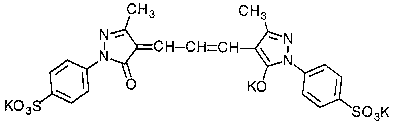


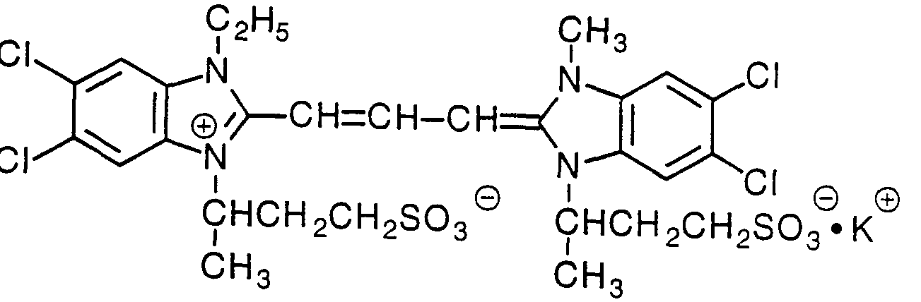


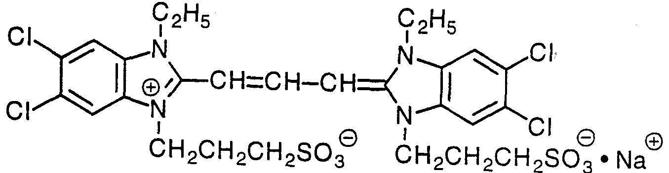


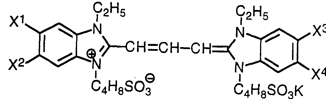


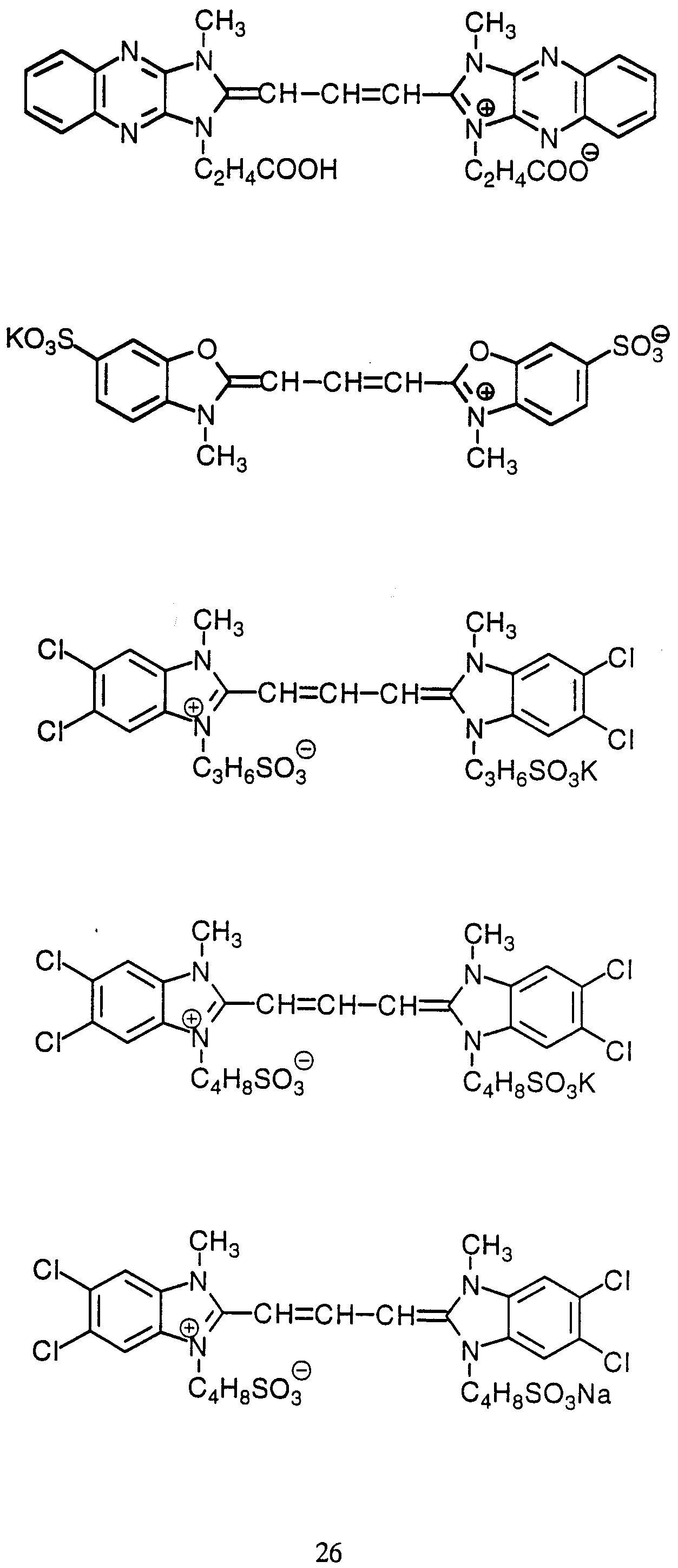


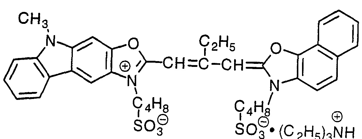


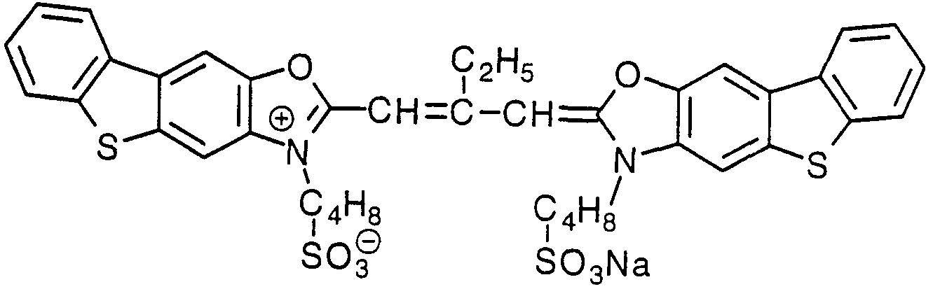


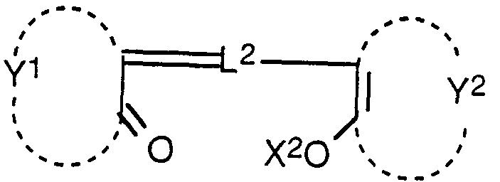


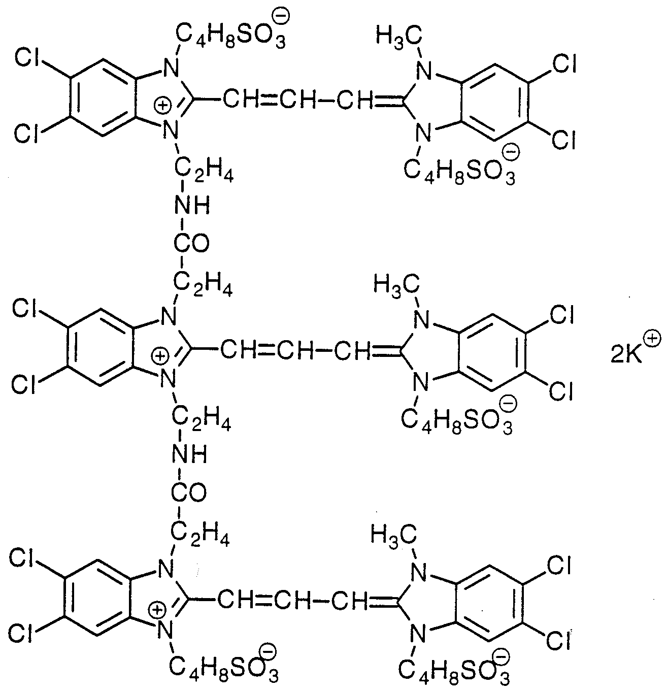


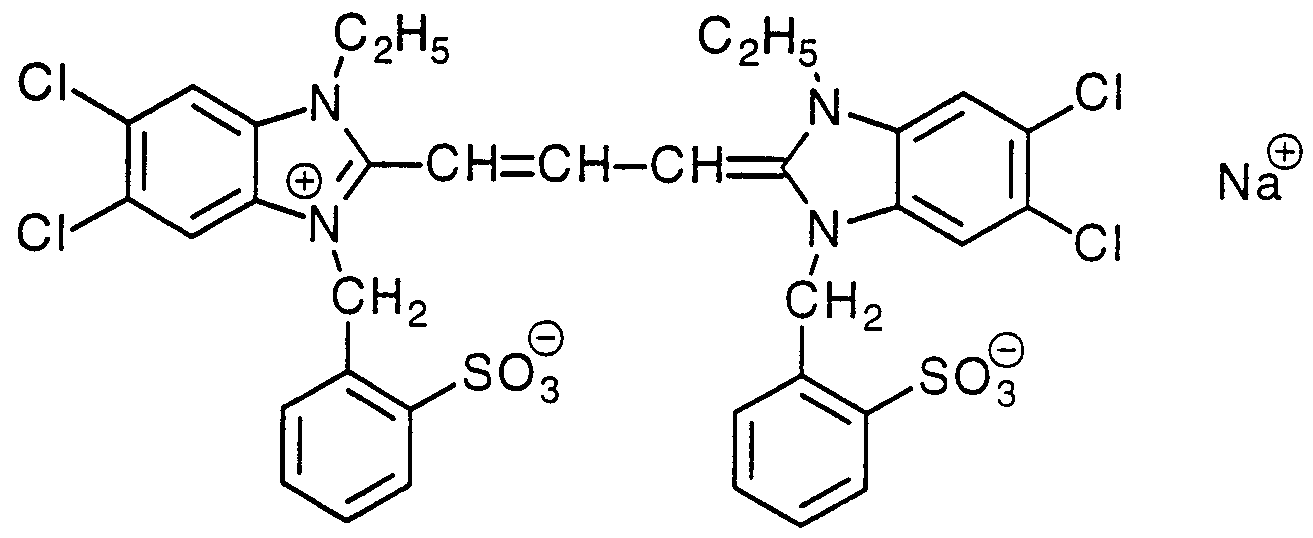


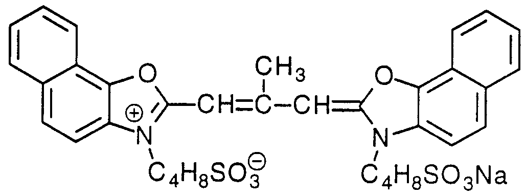


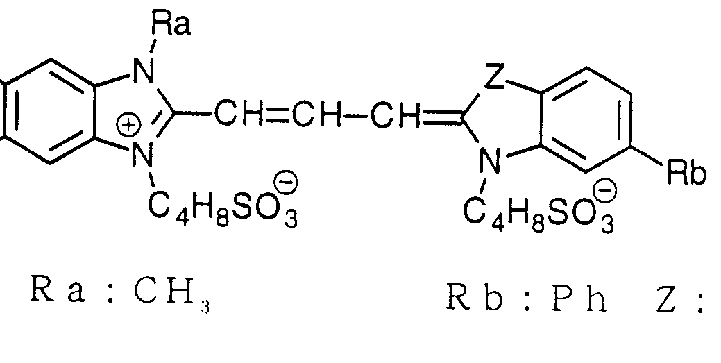


Claims


Priority Applications (4)
| Application Number | Priority Date | Filing Date | Title |
|---|---|---|---|
| US09/807,882 US6532120B1 (en) | 1998-10-20 | 1999-10-20 | Optical filter |
| AU22551/00A AU2255100A (en) | 1998-10-20 | 1999-10-20 | Optical filter |
| EP99970741A EP1124144A4 (en) | 1998-10-20 | 1999-10-20 | OPTICAL FILTER |
| JP2000577513A JP4533538B2 (ja) | 1998-10-20 | 1999-10-20 | 光学フィルター |
Applications Claiming Priority (12)
| Application Number | Priority Date | Filing Date | Title |
|---|---|---|---|
| JP31687698 | 1998-10-20 | ||
| JP10/316876 | 1998-10-20 | ||
| JP11/42080 | 1999-02-19 | ||
| JP4208099 | 1999-02-19 | ||
| JP12169999 | 1999-04-28 | ||
| JP11/121700 | 1999-04-28 | ||
| JP12170099 | 1999-04-28 | ||
| JP11/121699 | 1999-04-28 | ||
| JP11/124273 | 1999-04-30 | ||
| JP12427399 | 1999-04-30 | ||
| JP23424399 | 1999-08-20 | ||
| JP11/234243 | 1999-08-20 |
Publications (1)
| Publication Number | Publication Date |
|---|---|
| WO2000023829A1 true WO2000023829A1 (en) | 2000-04-27 |
Family
ID=27550065
Family Applications (1)
| Application Number | Title | Priority Date | Filing Date |
|---|---|---|---|
| PCT/JP1999/005785 Ceased WO2000023829A1 (en) | 1998-10-20 | 1999-10-20 | Optical filter |
Country Status (7)
| Country | Link |
|---|---|
| US (1) | US6532120B1 (ja) |
| EP (1) | EP1124144A4 (ja) |
| JP (1) | JP4533538B2 (ja) |
| KR (1) | KR100684343B1 (ja) |
| CN (1) | CN1295523C (ja) |
| AU (1) | AU2255100A (ja) |
| WO (1) | WO2000023829A1 (ja) |
Cited By (9)
| Publication number | Priority date | Publication date | Assignee | Title |
|---|---|---|---|---|
| JP2001228323A (ja) * | 2000-02-14 | 2001-08-24 | Bridgestone Corp | 光学フィルタ及びプラズマディスプレイパネル |
| JP2002187229A (ja) * | 2000-12-20 | 2002-07-02 | Bridgestone Corp | 光学特性を備えたフィルム及びプラズマディスプレイ前面保護フィルター |
| JP2002189422A (ja) * | 2000-12-19 | 2002-07-05 | Bridgestone Corp | プラズマディスプレイ用フィルム及び保護フィルター |
| JP2002277604A (ja) * | 2001-03-16 | 2002-09-25 | Toppan Printing Co Ltd | 反射防止フイルム |
| EP1253445A1 (en) * | 2001-04-27 | 2002-10-30 | Asahi Glass Co., Ltd. | Filter for plasma display panel |
| JP2002540442A (ja) * | 1999-01-21 | 2002-11-26 | 旭硝子株式会社 | カラー映像ディスプレイの画質向上フィルタ用染料組合わせ |
| US6849327B1 (en) | 1999-06-17 | 2005-02-01 | Fuji Photo Film Co., Ltd. | Optical filter |
| JP2005156935A (ja) * | 2003-11-26 | 2005-06-16 | Seed Co Ltd | 光学フィルター用組成物及び光学フィルター材料 |
| JP2010171007A (ja) * | 2008-12-25 | 2010-08-05 | Fujifilm Corp | 表示装置 |
Families Citing this family (20)
| Publication number | Priority date | Publication date | Assignee | Title |
|---|---|---|---|---|
| EP1521107A4 (en) * | 2002-07-04 | 2009-02-18 | Kyowa Hakko Chemical Co Ltd | FILTER FOR ELECTRONIC INDICATORS |
| KR100477611B1 (ko) * | 2002-07-26 | 2005-03-18 | 엘지전자 주식회사 | 플라즈마 디스플레이 패널의 컬러필터 |
| JP2004101916A (ja) * | 2002-09-10 | 2004-04-02 | Fujitsu Hitachi Plasma Display Ltd | ガス放電表示装置 |
| KR100578633B1 (ko) * | 2002-12-12 | 2006-05-11 | 삼성코닝 주식회사 | 투과율이 우수한 pdp용 전면 필터 |
| US6939612B2 (en) * | 2003-06-03 | 2005-09-06 | Solutia Incorporated | Fluorinated polymer sheets |
| EP1656572A1 (en) * | 2003-08-19 | 2006-05-17 | LG Chem, Ltd. | Film for plasma display filter and plasma display filter comprising the same |
| KR100683671B1 (ko) * | 2004-03-25 | 2007-02-15 | 삼성에스디아이 주식회사 | 전자기파 차폐층을 구비한 플라즈마 디스플레이 패널 |
| KR100815095B1 (ko) | 2004-05-28 | 2008-03-20 | 가부시키가이샤 닛폰 쇼쿠바이 | 투명 수지 재료 |
| JP4531763B2 (ja) * | 2004-06-23 | 2010-08-25 | 富士フイルム株式会社 | 透光性電磁波シールド膜およびその製造方法 |
| US7642303B2 (en) * | 2004-10-15 | 2010-01-05 | Shakely Thomas L | Thermoplastic articles for packaging UV sensitive materials, processes for the articles production and use and novel UV absorbers |
| US7182763B2 (en) * | 2004-11-23 | 2007-02-27 | Instrasurgical, Llc | Wound closure device |
| US7994702B2 (en) | 2005-04-27 | 2011-08-09 | Prysm, Inc. | Scanning beams displays based on light-emitting screens having phosphors |
| KR100705927B1 (ko) * | 2005-10-26 | 2007-04-12 | 제일모직주식회사 | 근적외선 흡수 및 색보정 점착제 조성물 및 이를 이용한필름 |
| JP2007141876A (ja) * | 2005-11-14 | 2007-06-07 | Sony Corp | 半導体撮像装置及びその製造方法 |
| WO2007131195A2 (en) * | 2006-05-05 | 2007-11-15 | Spudnik, Inc. | Phosphor compositions and other fluorescent materials for display systems and devices |
| US7655306B2 (en) * | 2006-05-23 | 2010-02-02 | Cheil Industries, Inc. | Optical film, optical filter and display device including the same |
| CN102736155B (zh) * | 2012-06-27 | 2014-07-09 | 四川长虹电器股份有限公司 | Pdp滤光膜及其制备方法 |
| DE102018116993B4 (de) * | 2018-07-13 | 2022-06-02 | Schott Ag | Optische Komponente mit kratzresistenter Anti-Reflexionsbeschichtung und Verfahren zu deren Herstellung |
| CN110646871A (zh) * | 2019-10-08 | 2020-01-03 | 苏州鑫河镜业有限公司 | 一种高强度防水抗菌汽车遮阳板镜片及其生产工艺 |
| CN112433285A (zh) * | 2020-12-04 | 2021-03-02 | 长春理工大学 | 吸收型窄带滤光片 |
Citations (6)
| Publication number | Priority date | Publication date | Assignee | Title |
|---|---|---|---|---|
| JPS61175601A (ja) * | 1985-01-31 | 1986-08-07 | Mitsubishi Metal Corp | 光選択吸収性合成樹脂板 |
| JPS62294205A (ja) * | 1986-06-13 | 1987-12-21 | Fuji Photo Film Co Ltd | 光学フイルタ−組成物 |
| US5210014A (en) * | 1991-03-28 | 1993-05-11 | Eastman Kodak Company | Mid-green sensitizing dyes for photographic materials |
| US5466822A (en) * | 1993-04-28 | 1995-11-14 | Fuji Photo Film Co., Ltd. | Benzimidazolocarbocyanine dye and silver halide photographic material containing said dye |
| JPH1064454A (ja) * | 1996-07-30 | 1998-03-06 | Chuka Eikan Kofun Yugenkoshi | ディスプレイ装置のコーティング |
| JPH10180947A (ja) * | 1996-11-07 | 1998-07-07 | Fuji Photo Film Co Ltd | 反射防止フイルムおよびそれを用いたプラズマディスプレイ |
Family Cites Families (14)
| Publication number | Priority date | Publication date | Assignee | Title |
|---|---|---|---|---|
| JPS58153904A (ja) * | 1982-03-08 | 1983-09-13 | Mitsubishi Rayon Co Ltd | プラスチツク系フイルタ− |
| JPS5915910A (ja) * | 1982-07-20 | 1984-01-27 | Yoshimi Matsuoka | プラスチツク防眩フイルタ−の製造方法 |
| JP2648224B2 (ja) * | 1990-07-12 | 1997-08-27 | 三菱レイヨン株式会社 | 光学フィルターなどの光学製品 |
| US5266238A (en) * | 1990-12-24 | 1993-11-30 | American Cyanamid Company | Narrow band radiation filter films |
| JP3690608B2 (ja) * | 1994-04-06 | 2005-08-31 | 共同印刷株式会社 | 着色層をもつ光学フィルタ |
| US5672655A (en) * | 1994-09-13 | 1997-09-30 | Kureha Kagaku Kogyo Kabushiki Kaisha | Plastic optical material and production process thereof |
| JPH0992162A (ja) * | 1995-09-20 | 1997-04-04 | Hitachi Ltd | プラズマディスプレイパネル |
| KR100396934B1 (ko) * | 1995-11-21 | 2003-12-31 | 세이코 엡슨 가부시키가이샤 | 안료물질을기판에부착시키는방법,컬러필터의제조방법및전기분해장치및그컬러필터를탑재한액정표시장치 |
| US5834122A (en) * | 1996-11-25 | 1998-11-10 | Hoechst Celanese Corp. | Spectrally tuned multiple bandpass filters for video displays |
| JP3410024B2 (ja) * | 1998-06-18 | 2003-05-26 | 富士通株式会社 | ガス放電表示装置 |
| JP2000193820A (ja) * | 1998-10-20 | 2000-07-14 | Fuji Photo Film Co Ltd | 光学フィルタ― |
| US6323585B1 (en) * | 1998-11-02 | 2001-11-27 | Corning Incorporated | Ultraviolet absorbing and yellow light filtering glasses for lamp envelopes |
| US20020005509A1 (en) * | 1999-01-21 | 2002-01-17 | Chia-Chi Teng | Dye combinations for image enhancement filters for color video displays |
| JP2001166131A (ja) * | 1999-09-29 | 2001-06-22 | Fuji Photo Film Co Ltd | 光学フィルターおよび反射防止膜 |
-
1999
- 1999-10-20 CN CNB998147362A patent/CN1295523C/zh not_active Expired - Lifetime
- 1999-10-20 AU AU22551/00A patent/AU2255100A/en not_active Abandoned
- 1999-10-20 US US09/807,882 patent/US6532120B1/en not_active Expired - Lifetime
- 1999-10-20 JP JP2000577513A patent/JP4533538B2/ja not_active Expired - Fee Related
- 1999-10-20 EP EP99970741A patent/EP1124144A4/en not_active Withdrawn
- 1999-10-20 WO PCT/JP1999/005785 patent/WO2000023829A1/ja not_active Ceased
- 1999-10-20 KR KR1020017004964A patent/KR100684343B1/ko not_active Expired - Lifetime
Patent Citations (6)
| Publication number | Priority date | Publication date | Assignee | Title |
|---|---|---|---|---|
| JPS61175601A (ja) * | 1985-01-31 | 1986-08-07 | Mitsubishi Metal Corp | 光選択吸収性合成樹脂板 |
| JPS62294205A (ja) * | 1986-06-13 | 1987-12-21 | Fuji Photo Film Co Ltd | 光学フイルタ−組成物 |
| US5210014A (en) * | 1991-03-28 | 1993-05-11 | Eastman Kodak Company | Mid-green sensitizing dyes for photographic materials |
| US5466822A (en) * | 1993-04-28 | 1995-11-14 | Fuji Photo Film Co., Ltd. | Benzimidazolocarbocyanine dye and silver halide photographic material containing said dye |
| JPH1064454A (ja) * | 1996-07-30 | 1998-03-06 | Chuka Eikan Kofun Yugenkoshi | ディスプレイ装置のコーティング |
| JPH10180947A (ja) * | 1996-11-07 | 1998-07-07 | Fuji Photo Film Co Ltd | 反射防止フイルムおよびそれを用いたプラズマディスプレイ |
Non-Patent Citations (1)
| Title |
|---|
| See also references of EP1124144A4 * |
Cited By (12)
| Publication number | Priority date | Publication date | Assignee | Title |
|---|---|---|---|---|
| JP2002540442A (ja) * | 1999-01-21 | 2002-11-26 | 旭硝子株式会社 | カラー映像ディスプレイの画質向上フィルタ用染料組合わせ |
| US6849327B1 (en) | 1999-06-17 | 2005-02-01 | Fuji Photo Film Co., Ltd. | Optical filter |
| US7357981B2 (en) | 1999-06-17 | 2008-04-15 | Fujifilm Corporation | Optical filter |
| JP2001228323A (ja) * | 2000-02-14 | 2001-08-24 | Bridgestone Corp | 光学フィルタ及びプラズマディスプレイパネル |
| JP2002189422A (ja) * | 2000-12-19 | 2002-07-05 | Bridgestone Corp | プラズマディスプレイ用フィルム及び保護フィルター |
| JP2002187229A (ja) * | 2000-12-20 | 2002-07-02 | Bridgestone Corp | 光学特性を備えたフィルム及びプラズマディスプレイ前面保護フィルター |
| JP2002277604A (ja) * | 2001-03-16 | 2002-09-25 | Toppan Printing Co Ltd | 反射防止フイルム |
| EP1253445A1 (en) * | 2001-04-27 | 2002-10-30 | Asahi Glass Co., Ltd. | Filter for plasma display panel |
| EP1398652A3 (en) * | 2001-04-27 | 2004-06-23 | Asahi Glass Co., Ltd. | Filter for plasma display panel |
| US7071602B2 (en) | 2001-04-27 | 2006-07-04 | Asahi Glass Company, Limited | Filter for plasma display panel |
| JP2005156935A (ja) * | 2003-11-26 | 2005-06-16 | Seed Co Ltd | 光学フィルター用組成物及び光学フィルター材料 |
| JP2010171007A (ja) * | 2008-12-25 | 2010-08-05 | Fujifilm Corp | 表示装置 |
Also Published As
| Publication number | Publication date |
|---|---|
| JP4533538B2 (ja) | 2010-09-01 |
| AU2255100A (en) | 2000-05-08 |
| KR20010085943A (ko) | 2001-09-07 |
| CN1331806A (zh) | 2002-01-16 |
| EP1124144A1 (en) | 2001-08-16 |
| EP1124144A4 (en) | 2010-12-01 |
| CN1295523C (zh) | 2007-01-17 |
| KR100684343B1 (ko) | 2007-02-20 |
| US6532120B1 (en) | 2003-03-11 |
Similar Documents
| Publication | Publication Date | Title |
|---|---|---|
| WO2000023829A1 (en) | Optical filter | |
| KR100808210B1 (ko) | 두 개의 최대 흡광값을 가지는 광학 필터 | |
| JPWO2000023829A1 (ja) | 光学フィルター | |
| US6307671B1 (en) | Optical filter comprising transparent support and filter layer containing dye and binder polymer | |
| US6680009B2 (en) | Optical filter comprising transparent support and filter layer having three absorption maximums | |
| JP2002122731A (ja) | 光学フィルター | |
| JP2008250336A (ja) | 反射防止フイルムおよびそれを用いたプラズマディスプレイ | |
| US6309564B1 (en) | Optical filter comprising transparent support and filter layer containing dye and binder polymer | |
| US6157504A (en) | Optical filter comprising transparent support and filter layer having two absorption maximums | |
| JP4148548B2 (ja) | 反射防止フイルムおよびそれを用いたプラズマディスプレイ | |
| JP2002090521A (ja) | 光学フィルター | |
| JP2001147319A (ja) | 光学フィルターおよび反射防止膜 | |
| JP2010212027A (ja) | 表示装置 | |
| US6586057B1 (en) | Optical filter comprising transparent support and filter layer containing dye and binder polymer | |
| JP2003255105A (ja) | 透明反射防止膜、光学フィルター、および画像表示装置 | |
| JP2001166131A (ja) | 光学フィルターおよび反射防止膜 | |
| JP2002122729A (ja) | 光学フィルター | |
| JP2009109774A (ja) | 光学フィルターおよびそれを用いたプラズマディスプレイパネル | |
| JP2002372617A (ja) | 光学フィルターおよび画像表示装置 | |
| JP2002022935A (ja) | 光学フィルター | |
| JP2000258605A (ja) | 光学フィルターおよび反射防止膜 | |
| JP2000321419A (ja) | 光学フィルターおよび反射防止膜 | |
| JP2001066419A (ja) | 光学フィルターおよび反射防止膜 | |
| JP2002214426A (ja) | 光学フィルターおよびプラズマディスプレイパネル | |
| JP2000258618A (ja) | 光学フィルターおよび反射防止膜 |
Legal Events
| Date | Code | Title | Description |
|---|---|---|---|
| WWE | Wipo information: entry into national phase |
Ref document number: 99814736.2 Country of ref document: CN |
|
| AK | Designated states |
Kind code of ref document: A1 Designated state(s): AE AL AM AT AU AZ BA BB BG BR BY CA CH CN CR CU CZ DE DK DM EE ES FI GB GD GE GH GM HR HU ID IL IN IS JP KE KG KP KR KZ LC LK LR LS LT LU LV MD MG MK MN MW MX NO NZ PL PT RO RU SD SE SG SI SK SL TJ TM TR TT TZ UA UG US UZ VN YU ZA ZW |
|
| AL | Designated countries for regional patents |
Kind code of ref document: A1 Designated state(s): GH GM KE LS MW SD SL SZ TZ UG ZW AM AZ BY KG KZ MD RU TJ TM AT BE CH CY DE DK ES FI FR GB GR IE IT LU MC NL PT SE BF BJ CF CG CI CM GA GN GW ML MR NE SN TD TG |
|
| 121 | Ep: the epo has been informed by wipo that ep was designated in this application | ||
| DFPE | Request for preliminary examination filed prior to expiration of 19th month from priority date (pct application filed before 20040101) | ||
| ENP | Entry into the national phase |
Ref document number: 2000 577513 Country of ref document: JP Kind code of ref document: A |
|
| WWE | Wipo information: entry into national phase |
Ref document number: 09807882 Country of ref document: US Ref document number: 1020017004964 Country of ref document: KR Ref document number: 1999970741 Country of ref document: EP |
|
| WWP | Wipo information: published in national office |
Ref document number: 1999970741 Country of ref document: EP |
|
| REG | Reference to national code |
Ref country code: DE Ref legal event code: 8642 |
|
| WWP | Wipo information: published in national office |
Ref document number: 1020017004964 Country of ref document: KR |
|
| WWG | Wipo information: grant in national office |
Ref document number: 1020017004964 Country of ref document: KR |