WO2001002121A1 - Structure et procede d'assemblage d'elements metalliques - Google Patents
Structure et procede d'assemblage d'elements metalliques Download PDFInfo
- Publication number
- WO2001002121A1 WO2001002121A1 PCT/JP2000/004350 JP0004350W WO0102121A1 WO 2001002121 A1 WO2001002121 A1 WO 2001002121A1 JP 0004350 W JP0004350 W JP 0004350W WO 0102121 A1 WO0102121 A1 WO 0102121A1
- Authority
- WO
- WIPO (PCT)
- Prior art keywords
- solder
- plating
- joining
- metal
- metal members
- Prior art date
- Legal status (The legal status is an assumption and is not a legal conclusion. Google has not performed a legal analysis and makes no representation as to the accuracy of the status listed.)
- Ceased
Links
Classifications
-
- B—PERFORMING OPERATIONS; TRANSPORTING
- B23—MACHINE TOOLS; METAL-WORKING NOT OTHERWISE PROVIDED FOR
- B23K—SOLDERING OR UNSOLDERING; WELDING; CLADDING OR PLATING BY SOLDERING OR WELDING; CUTTING BY APPLYING HEAT LOCALLY, e.g. FLAME CUTTING; WORKING BY LASER BEAM
- B23K35/00—Rods, electrodes, materials, or media, for use in soldering, welding, or cutting
- B23K35/001—Interlayers, transition pieces for metallurgical bonding of workpieces
-
- B—PERFORMING OPERATIONS; TRANSPORTING
- B23—MACHINE TOOLS; METAL-WORKING NOT OTHERWISE PROVIDED FOR
- B23K—SOLDERING OR UNSOLDERING; WELDING; CLADDING OR PLATING BY SOLDERING OR WELDING; CUTTING BY APPLYING HEAT LOCALLY, e.g. FLAME CUTTING; WORKING BY LASER BEAM
- B23K35/00—Rods, electrodes, materials, or media, for use in soldering, welding, or cutting
- B23K35/22—Rods, electrodes, materials, or media, for use in soldering, welding, or cutting characterised by the composition or nature of the material
- B23K35/24—Selection of soldering or welding materials proper
- B23K35/26—Selection of soldering or welding materials proper with the principal constituent melting at less than 400°C
-
- B—PERFORMING OPERATIONS; TRANSPORTING
- B23—MACHINE TOOLS; METAL-WORKING NOT OTHERWISE PROVIDED FOR
- B23K—SOLDERING OR UNSOLDERING; WELDING; CLADDING OR PLATING BY SOLDERING OR WELDING; CUTTING BY APPLYING HEAT LOCALLY, e.g. FLAME CUTTING; WORKING BY LASER BEAM
- B23K1/00—Soldering, e.g. brazing, or unsoldering
- B23K1/0008—Soldering, e.g. brazing, or unsoldering specially adapted for particular articles or work
-
- B—PERFORMING OPERATIONS; TRANSPORTING
- B23—MACHINE TOOLS; METAL-WORKING NOT OTHERWISE PROVIDED FOR
- B23K—SOLDERING OR UNSOLDERING; WELDING; CLADDING OR PLATING BY SOLDERING OR WELDING; CUTTING BY APPLYING HEAT LOCALLY, e.g. FLAME CUTTING; WORKING BY LASER BEAM
- B23K1/00—Soldering, e.g. brazing, or unsoldering
- B23K1/002—Soldering by means of induction heating
-
- B—PERFORMING OPERATIONS; TRANSPORTING
- B23—MACHINE TOOLS; METAL-WORKING NOT OTHERWISE PROVIDED FOR
- B23K—SOLDERING OR UNSOLDERING; WELDING; CLADDING OR PLATING BY SOLDERING OR WELDING; CUTTING BY APPLYING HEAT LOCALLY, e.g. FLAME CUTTING; WORKING BY LASER BEAM
- B23K1/00—Soldering, e.g. brazing, or unsoldering
- B23K1/19—Soldering, e.g. brazing, or unsoldering taking account of the properties of the materials to be soldered
-
- B—PERFORMING OPERATIONS; TRANSPORTING
- B23—MACHINE TOOLS; METAL-WORKING NOT OTHERWISE PROVIDED FOR
- B23K—SOLDERING OR UNSOLDERING; WELDING; CLADDING OR PLATING BY SOLDERING OR WELDING; CUTTING BY APPLYING HEAT LOCALLY, e.g. FLAME CUTTING; WORKING BY LASER BEAM
- B23K1/00—Soldering, e.g. brazing, or unsoldering
- B23K1/20—Preliminary treatment of work or areas to be soldered, e.g. in respect of a galvanic coating
-
- B—PERFORMING OPERATIONS; TRANSPORTING
- B23—MACHINE TOOLS; METAL-WORKING NOT OTHERWISE PROVIDED FOR
- B23K—SOLDERING OR UNSOLDERING; WELDING; CLADDING OR PLATING BY SOLDERING OR WELDING; CUTTING BY APPLYING HEAT LOCALLY, e.g. FLAME CUTTING; WORKING BY LASER BEAM
- B23K35/00—Rods, electrodes, materials, or media, for use in soldering, welding, or cutting
- B23K35/001—Interlayers, transition pieces for metallurgical bonding of workpieces
- B23K35/004—Interlayers, transition pieces for metallurgical bonding of workpieces at least one of the workpieces being of a metal of the iron group
-
- B—PERFORMING OPERATIONS; TRANSPORTING
- B23—MACHINE TOOLS; METAL-WORKING NOT OTHERWISE PROVIDED FOR
- B23K—SOLDERING OR UNSOLDERING; WELDING; CLADDING OR PLATING BY SOLDERING OR WELDING; CUTTING BY APPLYING HEAT LOCALLY, e.g. FLAME CUTTING; WORKING BY LASER BEAM
- B23K2101/00—Articles made by soldering, welding or cutting
- B23K2101/006—Vehicles
-
- B—PERFORMING OPERATIONS; TRANSPORTING
- B23—MACHINE TOOLS; METAL-WORKING NOT OTHERWISE PROVIDED FOR
- B23K—SOLDERING OR UNSOLDERING; WELDING; CLADDING OR PLATING BY SOLDERING OR WELDING; CUTTING BY APPLYING HEAT LOCALLY, e.g. FLAME CUTTING; WORKING BY LASER BEAM
- B23K2101/00—Articles made by soldering, welding or cutting
- B23K2101/04—Tubular or hollow articles
- B23K2101/12—Vessels
-
- B—PERFORMING OPERATIONS; TRANSPORTING
- B23—MACHINE TOOLS; METAL-WORKING NOT OTHERWISE PROVIDED FOR
- B23K—SOLDERING OR UNSOLDERING; WELDING; CLADDING OR PLATING BY SOLDERING OR WELDING; CUTTING BY APPLYING HEAT LOCALLY, e.g. FLAME CUTTING; WORKING BY LASER BEAM
- B23K35/00—Rods, electrodes, materials, or media, for use in soldering, welding, or cutting
- B23K35/22—Rods, electrodes, materials, or media, for use in soldering, welding, or cutting characterised by the composition or nature of the material
- B23K35/24—Selection of soldering or welding materials proper
- B23K35/26—Selection of soldering or welding materials proper with the principal constituent melting at less than 400°C
- B23K35/262—Sn as the principal constituent
-
- Y—GENERAL TAGGING OF NEW TECHNOLOGICAL DEVELOPMENTS; GENERAL TAGGING OF CROSS-SECTIONAL TECHNOLOGIES SPANNING OVER SEVERAL SECTIONS OF THE IPC; TECHNICAL SUBJECTS COVERED BY FORMER USPC CROSS-REFERENCE ART COLLECTIONS [XRACs] AND DIGESTS
- Y10—TECHNICAL SUBJECTS COVERED BY FORMER USPC
- Y10S—TECHNICAL SUBJECTS COVERED BY FORMER USPC CROSS-REFERENCE ART COLLECTIONS [XRACs] AND DIGESTS
- Y10S428/00—Stock material or miscellaneous articles
- Y10S428/922—Static electricity metal bleed-off metallic stock
- Y10S428/923—Physical dimension
- Y10S428/924—Composite
- Y10S428/926—Thickness of individual layer specified
-
- Y—GENERAL TAGGING OF NEW TECHNOLOGICAL DEVELOPMENTS; GENERAL TAGGING OF CROSS-SECTIONAL TECHNOLOGIES SPANNING OVER SEVERAL SECTIONS OF THE IPC; TECHNICAL SUBJECTS COVERED BY FORMER USPC CROSS-REFERENCE ART COLLECTIONS [XRACs] AND DIGESTS
- Y10—TECHNICAL SUBJECTS COVERED BY FORMER USPC
- Y10T—TECHNICAL SUBJECTS COVERED BY FORMER US CLASSIFICATION
- Y10T428/00—Stock material or miscellaneous articles
- Y10T428/12—All metal or with adjacent metals
- Y10T428/12493—Composite; i.e., plural, adjacent, spatially distinct metal components [e.g., layers, joint, etc.]
- Y10T428/12708—Sn-base component
-
- Y—GENERAL TAGGING OF NEW TECHNOLOGICAL DEVELOPMENTS; GENERAL TAGGING OF CROSS-SECTIONAL TECHNOLOGIES SPANNING OVER SEVERAL SECTIONS OF THE IPC; TECHNICAL SUBJECTS COVERED BY FORMER USPC CROSS-REFERENCE ART COLLECTIONS [XRACs] AND DIGESTS
- Y10—TECHNICAL SUBJECTS COVERED BY FORMER USPC
- Y10T—TECHNICAL SUBJECTS COVERED BY FORMER US CLASSIFICATION
- Y10T428/00—Stock material or miscellaneous articles
- Y10T428/12—All metal or with adjacent metals
- Y10T428/12493—Composite; i.e., plural, adjacent, spatially distinct metal components [e.g., layers, joint, etc.]
- Y10T428/12771—Transition metal-base component
- Y10T428/12785—Group IIB metal-base component
- Y10T428/12792—Zn-base component
Definitions
- the present invention relates to a joint structure of a metal member suitable for application to a joint structure between a tank and a pipe, for example, a fuel tank for an automobile, and particularly to a technique for improving corrosion resistance and sealability without using Pb. .
- a fuel tank 1 for vehicles as shown in Fig. 10 includes a filler neck pipe 2 for refueling, a breather pipe 3 for bleeding air at the time of refueling, and a pressure pipe for releasing pressure in the fuel tank 1.
- Pipes such as vent pipe 4 are joined.
- one end of the pipe P is press-fitted into the fuel tank 1 as shown in Fig. 11, and then close to the boundary between the pipe P and the fuel tank 1.
- a ring-shaped solder S is arranged, and the solder S is heated and melted by the electrode 6 for high-frequency induction heating.
- the molten solder S is solidified at the corner of the boundary between the pipe P and the fuel tank 1, and the two are air-tightly joined.
- Pb-Sn alloys have been a typical solder, but the use of Pb is restricted due to environmental regulations such as Pb elution from industrial waste such as shredder dust. Is not preferred, and alternative materials are required. For this reason, in recent years, Ag alloys, Cu and Cu—Zn alloys, Zn—A1 alloys and the like have been used, and disclosed in Japanese Patent Application Laid-Open No. H10-71488. As is known, Sn alloy (SnAg-based) solder is also known.
- a surface-treated steel sheet subjected to Zn plating, A1 alloy plating, Zn alloy plating, or the like is used as a material for the fuel tank and the pipe.
- post-treatment plating in which plating is performed after processing the material from the steel sheet, may be performed, but in any case, as shown in Fig. 12, the fuel tank with plating Ml, M2 1 and pipes P are joined with solder S.
- solder S for these joints is because the heating temperature is lower than other methods such as welding, and parts where dimensional accuracy is required for thin plates This is because the thermal distortion of the steel can be suppressed, the sealing performance is good, and the equipment can be made compact.
- the soldered part is required to have a sealing property that can withstand high internal pressure, and vibration and acceleration during driving of the automobile are required.
- the reliability and durability that do not impair the function are required.
- fuel tanks are often located under the floor of the vehicle body, and are exposed to harsh road and weather environments such as snow melting salt, mud, water, humidity, and stepping stones. Resistance and corrosion resistance are required.
- gasoline in the fuel tank deteriorates, corrosive components such as acids and peroxides are generated, so that the inner surface is also required to have corrosion resistance.
- the heating during soldering also heats the plating in the vicinity, so that there was a problem that the plating was thermally degraded.
- the solder in order to enhance the soldering property (wetting property) of the solder and to firmly fix it to the member, the solder must be 50 ° C lower than the melting point of the solder.
- the pipe wall immediately above the high-frequency heating electrode becomes particularly hot, and the plated metal alloys with the material Fe to reduce the corrosion resistance and make the plating itself brittle.
- the plating M2 melts and flows down, or as shown in FIG. 13 (b), the plating M2 oxidizes to form a porous oxide film M3. And the corrosion resistance is greatly reduced, and in the latter case, the paintability is also reduced. .
- an object of the present invention is to provide a joining structure and a joining method of a metal member that can ensure high reliability and durability even under severe use conditions. Specifically, the present invention selects plating and solder materials in consideration of the following points.
- the present inventors have studied plating and solder materials from the above viewpoints.
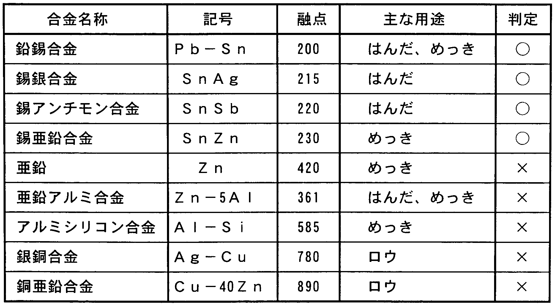
- the melting points of various alloys or metals are listed below from the viewpoint of preventing thermal degradation of plating. From the comparison in Table 1, it is expected that the zinc-copper-zinc alloy has a high melting point, and that thermal degradation such as oxidation of the plating material (lead-tin alloy etc.) will occur. Therefore, tin-silver alloy to tin-zinc alloy are preferable as the solder material.
- Automotive fuel tanks are required to have corrosion resistance to the external environment and corrosion resistance to acids and peroxides generated by fuel deterioration. Therefore, whether it functions as an appropriate anticorrosion for Fe, which is a material in a saltwater environment (external corrosion resistance), or whether it has stability against degraded gasoline containing formic acid and acetic acid (internal corrosion resistance), On metal
- the corresponding evaluation is shown in Table 2. From the comparison in Table 2, aluminum plating and tin-zinc alloy are suitable as plating materials.
- Fig. 1 shows the sequence of corrosion potentials of various metals in seawater.
- the contact corrosion resistance of various combinations of metals was evaluated and listed in Table 3.
- " ⁇ " indicates that the solderability is the same as that of lead-tin solder and lead-tin plating
- “mu” indicates that it is somewhat inferior but is within the allowable range
- Tables where possible are indicated in Table 3 as “X”.
- the combination of tin and zinc alloys has the best contact oxidation resistance.
- the zinc oxide is generated on the surface of the molten metal during soldering, so that it has poor throwing power and is hardly practical.
- the combination of tin-silver alloy solder and tin-zinc alloy plating Good throwing power and acceptable contact corrosion resistance. These alloys also have low melting points and excellent internal and external corrosion resistance.
- the present invention has been made based on the above-described study, and in a joint structure of a metal member in which a first metal member and a second metal member are joined by solder, at least one of the first and second metal members Has a SnZn alloy, and the solder is a SnAg alloy. .
- the melting point of the solder and that of the plating are close to each other, so that they are easily melted with each other. Therefore, it is possible to obtain a sealing property that can withstand high internal pressure inside the fuel tank, and a reliability and durability that does not impair the function against vibration and acceleration during running of the vehicle.
- the heating temperature must be adjusted to the higher melting point. For this reason, the metal on the low melting point side is oxidized by overheating to form an oxide film, which makes the underlying Fe easily corroded and reduces the adhesion of the coating film. No trouble occurs.
- the plating is made of an SnZn alloy, the inner and outer corrosion resistance is excellent, and the difference in corrosion potential is small, so that the occurrence of contact corrosion is suppressed.
- the surface of the portion where the solder and the plating are fused has a Zn rich layer formed by alloying the solder with the SnZn alloy plating.
- the SnZn alloy plating has a composition of Sn: 93 to 55% by weight and Zn: 7 to 45% by weight.
- the content of Zn is less than 7% by weight, the amount of Zn as a corrosion inhibitor for Fe is small, and therefore, Fe is easily corroded, and the corrosion resistance in a salt water environment is reduced.
- the Zn content exceeds 45% by weight, Zn oxide is formed on the surface of the portion where the solder and the plating are fused, and it becomes porous. For this reason, the spreadability of the solder is deteriorated, and the fixing strength is reduced.
- the method for joining metal members of the present invention includes the steps of: joining the first metal member and the second metal member to each other; In a method of joining metal members to be joined by solder, at least one of the first and second metal members is subjected to an SnZn alloy plating, and the SnAg alloy is used as the solder, and a joint portion is formed. It is characterized by joining while cooling. ADVANTAGE OF THE INVENTION According to this invention, formation of the porous layer by the washout by overheating of plating and the oxidization of plating can be prevented reliably.
- one of the metal members is a hollow member such as a pipe
- an appropriate cooling effect can be obtained by supplying a gaseous coolant such as air or gas to the inside of the hollow member.
- soldering conditions were controlled by controlling the power supplied to the high-frequency heating electrode.However, since control by cooling is added, the range of power management is expanded and control becomes easier. The quality is also stable.
- FIG. 1 is a diagram showing the corrosion potential sequence of various metals.
- 2 (a) to 2 (d) are cross-sectional views showing details of a soldered portion.
- FIG. 3 is a diagram showing the Zn content on the surface of the soldered portion in relation to the Ag content.
- FIG. 4 is a diagram showing the relationship between the Zn content, the pipe-pulling strength, and the redness generation cycle.
- FIGS. 5 (a) to 5 (c) are longitudinal sectional views respectively showing a method of cooling a soldered portion.
- FIG. 6 is a longitudinal sectional view showing a temperature measuring point of a soldered portion.
- FIG. 7 is a diagram showing the temperature of each part of the soldering part.
- FIG. 8 is a diagram showing a relationship between electric power at the time of heating and temperatures of a solder portion and a plating portion.
- FIG. 9 is a diagram showing the control width of the heating power when the soldered portion is cooled and when it is not cooled.
- FIG. 10 is a perspective view showing a fuel tank.
- FIG. 11 is a perspective view showing a state where a pipe is soldered to a fuel tank.
- FIG. 12 is a longitudinal sectional view showing details of a soldered portion.
- FIGS. 13 (a) and (b) are longitudinal cross-sectional views showing a quality defect occurring in a soldered portion.
- the fuel tank (first metal member) 1 is a material 1a made of Fe with inner and outer surfaces coated with SnZn alloy M1 .
- the fuel tank 1 is press-fitted with a pipe (second metal member) P having an inner surface and an outer surface coated with SnZn alloy M2.
- the illustration of the plating on the inner side is omitted in the figure.
- a ring-shaped solder S is fitted to the pipe P, and the solder S is heated and melted by a high-frequency heating electrode (not shown) disposed close to the ring S.
- FIGS. 2 (b) and (c) show the state where the solder S has solidified.
- the plating Ml and M2 are alloyed with the solder S to form a Zn-rich layer R.
- the fuel tank 1 and the pipe P are coated, preferably through a pretreatment step, as shown in FIG. 2 (d), and they are covered with the coating film C.
- the zinc rich layer R is formed on the surface of the solder S, contact corrosion between the solder and the plating is prevented, and a conversion coating is formed in the pretreatment step. Good adhesion to coating film. Therefore, the corrosion resistance of the surface of the solder S can be significantly improved.
- solder of the present invention 311: 94 to 98% by weight and Ag: 2 to 6% by weight are preferable, but a third additive metal such as Zn, Cu, or Bi is preferably used. Less than 3% by weight may be contained. Further, in the present invention, it is sufficient that at least one of the first and second metal members is provided with an SnZn alloy plating, and the other metal member is subjected to Ni plating other than the SnZn alloy plating. It can be applied or not plated.
- the Zn content in the SnZn alloy plating is desirably 7 to 45% by weight.
- the amount of Zn as a corrosion inhibitor for Fe is small, and therefore, Fe is easily corroded, and the corrosion resistance in a salt water environment is reduced.
- the content of Zn exceeds 45% by weight, an oxide of Zn is formed in a region indicated by the symbol Z in FIG. 2 (c) of the solder S, and it becomes porous. As a result, the solderability of the solder deteriorates, and the fixing strength decreases.
- the thickness of the SnZn alloy plating is preferably 3 to 13.
- chromate on the surface of the SnZn alloy Providing a treated film, an organic film with a thickness of 1 m or less, or an inorganic composite film further improves the corrosion resistance.
- Each joint structure was subjected to a composite corrosion test based on the automotive standard (JASOM 61-92) to examine the corrosion resistance.
- This combined corrosion test 1 35 Spray with NaC1 aqueous solution at ° C for 2 hours, 2 Dry at 60 ° C in an atmosphere with a relative humidity of 20 to 30% for 4 hours, and 3 At 50 ° C, the relative humidity is 95 % For 2 hours.
- Steps (1) to (3) were defined as one cycle, and the number of cycles until red mackerel was generated in the joint structure was counted.
- the pipe was pulled upward with respect to the steel plate in the state shown in Fig. 12, and the pipe removal load was measured.
- the state of the solder before painting was visually observed to evaluate the throwing power.
- the results are shown in Table 5.
- the spreadability of the solder is ⁇ when the combination is the same as the most commonly used combination of Pb-Sn plating and Pb-Sn solder.
- the case of the allowable range was marked with ⁇ , and the case of defective solder was marked with X.
- Example 5 As can be seen from Table 5, the joint structures of Examples 1 to 3 have a high value of around 950 kg ⁇ due to their excellent solderability, and have good corrosion resistance. is there.
- Examples 4 and 6 since the content of ⁇ in the S ⁇ ⁇ ⁇ alloy plating was relatively high, oxides of ⁇ were generated during soldering and plating during plating, and the Although the pipe pulling load was slightly reduced, it is within the range where there is no problem in practical use. Further, in Example 5, since the adhesion of the member ⁇ is not Ni (which is more noble than Fe), the corrosion resistance is slightly reduced, but there is no practical problem. In Comparative Example 1, the plating is Ni with a high melting point, so the plating melts during soldering.
- Comparative Example 1 It showed good solderability and pipe pull-out load.
- the plating of Comparative Example 1 was inferior in corrosion resistance because it was Ni.
- Comparative Example 2 since the Zn content of the plating was high, oxides of Zn were formed in a porous manner in the alloy layer between the solder and the plating, and the spreadability of the solder was extremely deteriorated.
- the plating of the members A and B is Zn and ZnNi whose corrosion potential ranks are far apart from the SnAg alloy. For this reason, contact corrosion occurred with the plating, and the corrosion resistance was further inferior.
- FIG. 3 is a diagram showing the contents of Zn and Ag on the surface of the solder in Examples 1 to 5 and Comparative Example 1. As is clear from FIG. 3, as the Zn content of the plating increases, a richer Zn layer is formed on the surface of the Sn Ag alloy solder. The Zn-rich layer suppresses the contact corrosion between the solder and the plating, improves the adhesion of the coating film, and obtains the excellent corrosion resistance as described above.
- the plating of the members A and B is made of an SnZn alloy having the same Zn content, and the Zn content of the plating is changed stepwise from 0 to 100% by weight.
- the bonded member was manufactured.
- the pipe removal load of the joined members was measured, and the results are shown in FIG.
- the pipe unloading load increases as the Zn content increases, but decreases rapidly when the load exceeds 45% by weight. This is because Zn oxide is formed in the alloy layer between the solder and the plating in a brittle porous state. From this result, it is understood that the Zn content of the plating is preferably 45% by weight or less.
- Example 2 a composite corrosion test was performed under the same conditions as in Example 1 for those with a Zn content of 0 to 55% by weight, and the results are also shown in FIG. As can be seen from FIG. 4, when the Zn content is less than 7% by weight, the function of Zn as a corrosion inhibitor cannot be obtained, and the corrosion resistance rapidly decreases. This shows that the Zn content of the plating is preferably 7% by weight or more.
- FIG. 5 is a diagram showing a method of soldering while cooling the pipe, and (a) (B) shows a method of cooling the outer surface of the pipe with a refrigerant, and (c) shows a method of dissipating and dissipating heat by attaching radiation fins to the upper end of the pipe. ing.
- Example 3 of the above-mentioned first example was carried out using the cooling method shown in FIGS. 5 (a) to 5 (c) together. The cooling effect was examined by measuring the temperature of the joint structure shown in Fig. 6 at that time, and the quality of the soldered part (turning property) and corrosion resistance were investigated in the same manner as in the first embodiment. Table 6 shows the results.
- the cooling methods (a-2) and (a-3) resulted in excessive cooling, especially at the interface between the pipe and the solder, resulting in insufficient solder quality.
- the cooling method (b-1) a wavy shear due to the refrigerant occurs on the surface of the unsolidified solder, and in the cooling method (b-2), cracks occur due to rapid cooling on the solder surface. Did not satisfy the solder quality.
- the cooling method (c) without using a refrigerant could not obtain a sufficient effect for suppressing the temperature rise. After all, cooling inside the pipe (a_l) using air or gas as the refrigerant was the best with moderate cooling.
- FIG. 7 is a diagram showing the temperatures at points (A, B, C) shown in FIG. 6 in the cooling methods (a-1), (a-3) and (c). For comparison, the temperature without cooling was also shown. As shown in Fig. 7, in the cooling method (a-3), the temperature at point A is lower than the required heating temperature (approximately 340 ° C) due to excessive cooling, and poor solder penetration occurs. occured. In the case of the cooling method (c), The temperature was almost the same as the temperature.
- soldering was carried out by changing the cooling method with the combination of solder and plating shown in Table 7, and various characteristics of the produced joining members were examined and also shown in Table 7.
- the coating was performed by coating the joining member after soldering with an epoxy-based or melamine-based paint to a film thickness of about 20; am and drying for a standard time.
- the adhesion of the coating film was determined by immersing the coated product in ion-exchanged water at 40 ° C for 240 hours, taking it out, cutting a 1 mm square cross cut into the pipe surface with a knife, The cross section was peeled off using cellophane tape and evaluated.
- Fig. 8 shows the results.
- the heating temperature is lower than 340 ° C.
- poor penetration of solder occurs. Therefore, in order to raise the temperature at point A to 340 ° C or higher, the electric power during heating must be 1.6 kW or higher regardless of whether or not cooling is performed.
- the heating temperature exceeds 500 ° C, thermal degradation occurs. Therefore, if cooling is not performed, the power during heating must be 1.7 kW or less. Therefore, when cooling is not performed, as shown in Fig. 9, the electric power at the time of heating must be controlled in the range of 1.6 to 1.71 ⁇ ⁇ , that is, in the range of 0.1 kW.
- the temperature at point B when cooling is performed does not increase so rapidly with the increase in power during heating. For this reason, the temperature at point B can be reduced to 500 ° C or less even when the power during heating is increased to about 1.9 kW. Therefore, when cooling, as shown in Fig. 9, the electric power at the time of heating may be controlled between 1.6 and 1.9 kW, that is, within the range of 0.3 kW. This is extremely important for stabilizing quality. In other words, when performing soldering, the prevention of thermal deterioration of the plated part has been regarded as important, and the target temperature for heating must be controlled at a level close to the lower limit.
- the temperature of the solder part (point A) varies greatly depending on the distance between the electrode and the solder. Defects are more likely to occur.
- the allowable range of the heating temperature is widened by cooling, variations in the heating temperature of the solder can be absorbed, and the quality can be stabilized by simple management.
- the present invention is not limited to a structure such as a fuel tank and a pipe, but can be applied to any joining structure of metal members.
- At least one of the first and second metal members is coated with an SnZn alloy, and the solder is formed of an SnAg alloy. It is possible to prevent contact corrosion between sticks, improve the soldering property, and improve the quality of the joint structure such as corrosion resistance and joint strength.
Landscapes
- Engineering & Computer Science (AREA)
- Mechanical Engineering (AREA)
- Chemical & Material Sciences (AREA)
- Materials Engineering (AREA)
- Coating With Molten Metal (AREA)
- Electroplating Methods And Accessories (AREA)
- Non-Disconnectible Joints And Screw-Threaded Joints (AREA)
- Ceramic Products (AREA)
- Pressure Welding/Diffusion-Bonding (AREA)
Description


Claims
Priority Applications (4)
| Application Number | Priority Date | Filing Date | Title |
|---|---|---|---|
| EP00940905A EP1118413B1 (en) | 1999-06-30 | 2000-06-30 | Structure and method for joining metal members |
| US09/784,454 US6534195B1 (en) | 1999-06-30 | 2000-06-30 | Connection structure for metallic members and connecting method therefor |
| CA002341725A CA2341725C (en) | 1999-06-30 | 2000-06-30 | Structure and method for joining metal members |
| DE60034209T DE60034209T2 (de) | 1999-06-30 | 2000-06-30 | Struktur und verfahren zum verbinden von metallischen werkstücken |
Applications Claiming Priority (2)
| Application Number | Priority Date | Filing Date | Title |
|---|---|---|---|
| JP18564799A JP3762146B2 (ja) | 1999-06-30 | 1999-06-30 | 金属部材の接合構造および接合方法 |
| JP11/185647 | 1999-06-30 |
Publications (1)
| Publication Number | Publication Date |
|---|---|
| WO2001002121A1 true WO2001002121A1 (fr) | 2001-01-11 |
Family
ID=16174439
Family Applications (1)
| Application Number | Title | Priority Date | Filing Date |
|---|---|---|---|
| PCT/JP2000/004350 Ceased WO2001002121A1 (fr) | 1999-06-30 | 2000-06-30 | Structure et procede d'assemblage d'elements metalliques |
Country Status (8)
| Country | Link |
|---|---|
| US (1) | US6534195B1 (ja) |
| EP (1) | EP1118413B1 (ja) |
| JP (1) | JP3762146B2 (ja) |
| KR (1) | KR100432186B1 (ja) |
| CN (1) | CN1146484C (ja) |
| CA (1) | CA2341725C (ja) |
| DE (1) | DE60034209T2 (ja) |
| WO (1) | WO2001002121A1 (ja) |
Families Citing this family (12)
| Publication number | Priority date | Publication date | Assignee | Title |
|---|---|---|---|---|
| US6794060B2 (en) * | 1992-03-27 | 2004-09-21 | The Louis Berkman Company | Corrosion-resistant coated metal and method for making the same |
| US6652990B2 (en) * | 1992-03-27 | 2003-11-25 | The Louis Berkman Company | Corrosion-resistant coated metal and method for making the same |
| JP3910853B2 (ja) * | 2002-01-18 | 2007-04-25 | 東洋鋼鈑株式会社 | 電子部品用表面処理鋼板およびその製造方法 |
| JP4143478B2 (ja) * | 2002-10-02 | 2008-09-03 | アルプス電気株式会社 | はんだ接続構造および電子部品のはんだ接続方法 |
| US20060104033A1 (en) * | 2004-11-12 | 2006-05-18 | Chih-Chiang Yeh | Connection structure of thermal tube and heat dissipation fins |
| KR100766702B1 (ko) | 2006-10-30 | 2007-10-12 | 현대중공업 주식회사 | 선박 발라스트 탱크의 장수명화 방법 |
| JP2010085064A (ja) * | 2008-10-02 | 2010-04-15 | Panasonic Corp | 機械装置の製造方法及びこの方法で製造した冷凍サイクル装置 |
| CN101896049A (zh) * | 2009-05-19 | 2010-11-24 | 晟铭电子科技股份有限公司 | 一种散热模块及其制造方法 |
| JP6074648B2 (ja) * | 2012-07-20 | 2017-02-08 | パナソニックIpマネジメント株式会社 | 管部材の接合体、及び冷凍サイクル装置の熱交換器 |
| CN103192148A (zh) * | 2013-01-25 | 2013-07-10 | 鸿特机械发展(上海)有限公司 | 一种焊接式单刃枪钻的刀杆连接方法 |
| CN107097015A (zh) * | 2017-06-07 | 2017-08-29 | 廊坊邦壮电子材料有限公司 | 一种锡银合金焊料及其制备工艺 |
| CN116475700B (zh) * | 2023-04-28 | 2025-08-19 | 哈尔滨工业大学 | 一种使用铜锡磷钎料钎焊连接方钴矿与铜电极的方法 |
Citations (4)
| Publication number | Priority date | Publication date | Assignee | Title |
|---|---|---|---|---|
| JPH0663731A (ja) * | 1992-06-27 | 1994-03-08 | Hille & Mueller | 金属製の多層管及びその製造方法 |
| JPH0871741A (ja) * | 1994-08-31 | 1996-03-19 | At & T Corp | 電気部品 |
| JPH091381A (ja) * | 1995-06-20 | 1997-01-07 | Harima Chem Inc | 半田接合方法 |
| JPH11114667A (ja) * | 1997-10-13 | 1999-04-27 | Toshiba Corp | 金属部材の接合方法及び接合体 |
Family Cites Families (5)
| Publication number | Priority date | Publication date | Assignee | Title |
|---|---|---|---|---|
| US4695428A (en) * | 1986-08-21 | 1987-09-22 | J. W. Harris Company | Solder composition |
| JPH0577032A (ja) * | 1991-09-18 | 1993-03-30 | Nippon Light Metal Co Ltd | 金属材のろう付け方法 |
| GB2289691B (en) * | 1994-03-14 | 1999-09-29 | Berkman Louis Co | Coated metal |
| WO1997009455A1 (en) * | 1995-09-01 | 1997-03-13 | Sarnoff Corporation | Soldering composition |
| DE69632866T2 (de) * | 1995-09-29 | 2005-07-14 | Matsushita Electric Industrial Co., Ltd., Kadoma | Bleifreies lot |
-
1999
- 1999-06-30 JP JP18564799A patent/JP3762146B2/ja not_active Expired - Lifetime
-
2000
- 2000-06-30 US US09/784,454 patent/US6534195B1/en not_active Expired - Lifetime
- 2000-06-30 CA CA002341725A patent/CA2341725C/en not_active Expired - Lifetime
- 2000-06-30 WO PCT/JP2000/004350 patent/WO2001002121A1/ja not_active Ceased
- 2000-06-30 DE DE60034209T patent/DE60034209T2/de not_active Expired - Lifetime
- 2000-06-30 KR KR10-2001-7002568A patent/KR100432186B1/ko not_active Expired - Lifetime
- 2000-06-30 EP EP00940905A patent/EP1118413B1/en not_active Expired - Lifetime
- 2000-06-30 CN CNB008012318A patent/CN1146484C/zh not_active Expired - Lifetime
Patent Citations (4)
| Publication number | Priority date | Publication date | Assignee | Title |
|---|---|---|---|---|
| JPH0663731A (ja) * | 1992-06-27 | 1994-03-08 | Hille & Mueller | 金属製の多層管及びその製造方法 |
| JPH0871741A (ja) * | 1994-08-31 | 1996-03-19 | At & T Corp | 電気部品 |
| JPH091381A (ja) * | 1995-06-20 | 1997-01-07 | Harima Chem Inc | 半田接合方法 |
| JPH11114667A (ja) * | 1997-10-13 | 1999-04-27 | Toshiba Corp | 金属部材の接合方法及び接合体 |
Non-Patent Citations (1)
| Title |
|---|
| See also references of EP1118413A4 * |
Also Published As
| Publication number | Publication date |
|---|---|
| CA2341725C (en) | 2005-06-28 |
| DE60034209D1 (de) | 2007-05-16 |
| JP2001009569A (ja) | 2001-01-16 |
| CA2341725A1 (en) | 2001-01-11 |
| EP1118413B1 (en) | 2007-04-04 |
| JP3762146B2 (ja) | 2006-04-05 |
| CN1315894A (zh) | 2001-10-03 |
| KR100432186B1 (ko) | 2004-05-22 |
| KR20010079709A (ko) | 2001-08-22 |
| US6534195B1 (en) | 2003-03-18 |
| EP1118413A1 (en) | 2001-07-25 |
| DE60034209T2 (de) | 2007-12-20 |
| CN1146484C (zh) | 2004-04-21 |
| EP1118413A4 (en) | 2005-09-28 |
Similar Documents
| Publication | Publication Date | Title |
|---|---|---|
| JP4339690B2 (ja) | 低温フラックスレスろう付けのための合金組成物および方法 | |
| AU681155B2 (en) | A method of brazing | |
| US7451906B2 (en) | Products for use in low temperature fluxless brazing | |
| JP3762146B2 (ja) | 金属部材の接合構造および接合方法 | |
| JP2004535931A (ja) | 低融点の鑞付け製品 | |
| CN101825406A (zh) | 换热器 | |
| JP2012152789A (ja) | 異種金属板の重ね電気抵抗ろう付による接合方法およびそれによるろう付継手 | |
| CN1236886C (zh) | 一种制造钎焊异质金属部件组装体的方法 | |
| EP0916746A1 (en) | Preservative steel plate having high resistance weldability, corrosion resistance and press formability for automobile fuel tanks | |
| US20040121180A1 (en) | Brazing sheet product and method of its manufacture | |
| JP2006035294A (ja) | 接合部の耐食性に優れた亜鉛系合金めっき鋼板の接合方法 | |
| JP2006503709A (ja) | ロウ付用製品およびその製造方法 | |
| CN100339177C (zh) | 硬钎焊产品和制造硬钎焊产品的方法 | |
| JP2006509635A (ja) | クラッド層および鉄合金の被覆層を有するろう付けシート製品およびその製造方法 | |
| JPS6018294A (ja) | アルミニウムロ−付け継手 | |
| JP2000176644A (ja) | Al系めっき鋼板のアーク溶接方法 | |
| JP2004330266A (ja) | 積層型熱交換器の製造方法 | |
| JPH0688695A (ja) | アルミ製熱交換器用複合チューブとその製造方法 | |
| JP2000017450A (ja) | 耐食性に優れた自動車用燃料容器 | |
| JP2000167659A (ja) | めっき薄鋼板のmigろう付け方法 | |
| EP3616827B1 (en) | Junction structure, method for manufacturing same, electric motor, and method for manufacturing same | |
| JPH10291088A (ja) | 耐食性に優れた熱交換器およびその製造方法 | |
| JPH0796387A (ja) | Al接合用材料とそれを用いた接合部品の接合方法 | |
| JPH03114666A (ja) | Al又はAl合金の気相ろう付け方法 | |
| JPH0796364A (ja) | アルミ製熱交換器用複合チューブとその製造方法 |
Legal Events
| Date | Code | Title | Description |
|---|---|---|---|
| WWE | Wipo information: entry into national phase |
Ref document number: 00801231.8 Country of ref document: CN |
|
| AK | Designated states |
Kind code of ref document: A1 Designated state(s): CA CN KR US |
|
| AL | Designated countries for regional patents |
Kind code of ref document: A1 Designated state(s): AT BE CH CY DE DK ES FI FR GB GR IE IT LU MC NL PT SE |
|
| ENP | Entry into the national phase |
Ref document number: 2341725 Country of ref document: CA Ref document number: 2341725 Country of ref document: CA Kind code of ref document: A |
|
| WWE | Wipo information: entry into national phase |
Ref document number: 2000940905 Country of ref document: EP Ref document number: 1020017002568 Country of ref document: KR |
|
| 121 | Ep: the epo has been informed by wipo that ep was designated in this application | ||
| WWE | Wipo information: entry into national phase |
Ref document number: 09784454 Country of ref document: US |
|
| WWP | Wipo information: published in national office |
Ref document number: 2000940905 Country of ref document: EP |
|
| WWP | Wipo information: published in national office |
Ref document number: 1020017002568 Country of ref document: KR |
|
| WWG | Wipo information: grant in national office |
Ref document number: 1020017002568 Country of ref document: KR |
|
| WWG | Wipo information: grant in national office |
Ref document number: 2000940905 Country of ref document: EP |