WO2002016868A1 - Positional error evaluation method for mobile device and movement accuracy improving method based on the evaluation result - Google Patents
Positional error evaluation method for mobile device and movement accuracy improving method based on the evaluation result Download PDFInfo
- Publication number
- WO2002016868A1 WO2002016868A1 PCT/JP2001/000390 JP0100390W WO0216868A1 WO 2002016868 A1 WO2002016868 A1 WO 2002016868A1 JP 0100390 W JP0100390 W JP 0100390W WO 0216868 A1 WO0216868 A1 WO 0216868A1
- Authority
- WO
- WIPO (PCT)
- Prior art keywords
- error
- moving
- straightness
- axis direction
- measurement
- Prior art date
- Legal status (The legal status is an assumption and is not a legal conclusion. Google has not performed a legal analysis and makes no representation as to the accuracy of the status listed.)
- Ceased
Links
Classifications
-
- B—PERFORMING OPERATIONS; TRANSPORTING
- B82—NANOTECHNOLOGY
- B82Y—SPECIFIC USES OR APPLICATIONS OF NANOSTRUCTURES; MEASUREMENT OR ANALYSIS OF NANOSTRUCTURES; MANUFACTURE OR TREATMENT OF NANOSTRUCTURES
- B82Y15/00—Nanotechnology for interacting, sensing or actuating, e.g. quantum dots as markers in protein assays or molecular motors
-
- B—PERFORMING OPERATIONS; TRANSPORTING
- B23—MACHINE TOOLS; METAL-WORKING NOT OTHERWISE PROVIDED FOR
- B23Q—DETAILS, COMPONENTS, OR ACCESSORIES FOR MACHINE TOOLS, e.g. ARRANGEMENTS FOR COPYING OR CONTROLLING; MACHINE TOOLS IN GENERAL CHARACTERISED BY THE CONSTRUCTION OF PARTICULAR DETAILS OR COMPONENTS; COMBINATIONS OR ASSOCIATIONS OF METAL-WORKING MACHINES, NOT DIRECTED TO A PARTICULAR RESULT
- B23Q17/00—Arrangements for observing, indicating or measuring on machine tools
- B23Q17/24—Arrangements for observing, indicating or measuring on machine tools using optics or electromagnetic waves
-
- B—PERFORMING OPERATIONS; TRANSPORTING
- B25—HAND TOOLS; PORTABLE POWER-DRIVEN TOOLS; MANIPULATORS
- B25J—MANIPULATORS; CHAMBERS PROVIDED WITH MANIPULATION DEVICES
- B25J9/00—Program-controlled manipulators
- B25J9/16—Program controls
- B25J9/1656—Program controls characterised by programming, planning systems for manipulators
- B25J9/1669—Program controls characterised by programming, planning systems for manipulators characterised by special application, e.g. multi-arm co-operation, assembly, grasping
-
- G—PHYSICS
- G01—MEASURING; TESTING
- G01B—MEASURING LENGTH, THICKNESS OR SIMILAR LINEAR DIMENSIONS; MEASURING ANGLES; MEASURING AREAS; MEASURING IRREGULARITIES OF SURFACES OR CONTOURS
- G01B21/00—Measuring arrangements or details thereof, where the measuring technique is not covered by the other groups of this subclass, unspecified or not relevant
- G01B21/02—Measuring arrangements or details thereof, where the measuring technique is not covered by the other groups of this subclass, unspecified or not relevant for measuring length, width, or thickness
- G01B21/04—Measuring arrangements or details thereof, where the measuring technique is not covered by the other groups of this subclass, unspecified or not relevant for measuring length, width, or thickness by measuring coordinates of points
- G01B21/042—Calibration or calibration artifacts
-
- G—PHYSICS
- G01—MEASURING; TESTING
- G01B—MEASURING LENGTH, THICKNESS OR SIMILAR LINEAR DIMENSIONS; MEASURING ANGLES; MEASURING AREAS; MEASURING IRREGULARITIES OF SURFACES OR CONTOURS
- G01B21/00—Measuring arrangements or details thereof, where the measuring technique is not covered by the other groups of this subclass, unspecified or not relevant
- G01B21/02—Measuring arrangements or details thereof, where the measuring technique is not covered by the other groups of this subclass, unspecified or not relevant for measuring length, width, or thickness
- G01B21/04—Measuring arrangements or details thereof, where the measuring technique is not covered by the other groups of this subclass, unspecified or not relevant for measuring length, width, or thickness by measuring coordinates of points
- G01B21/045—Correction of measurements
Definitions
- the present invention is directed to a moving device such as a three-dimensional measuring device that moves a stylus in three-axis directions orthogonal to each other and a machine tool that moves a tool in a two-axis direction or a three-axis direction orthogonal to each other.
- the present invention relates to a method for evaluating the position error of a moving object as described above, and a method for improving the position accuracy using the evaluation method.
- the 3D measuring device has the function of evaluating the dimensions and shape accuracy, which is indispensable for production lines and production systems, as machining becomes more automated and more precise.
- the three-dimensional measuring device is used as hardware to improve the measurement accuracy more than it is now, it will result in difficulties in manufacturing technology and increase in manufacturing costs. For this reason, in recent years, by measuring the accuracy of the device at the time of shipment and correcting the movement of the tracing stylus, the accuracy of measurement, which is the basic performance of the device, has been improved.
- Fig. 14 shows an example of error measurement result display using a pole plate.
- (A) shows the direction and magnitude of the error with a bar
- (b) shows the error in the measurement plane by mesh deformation. ing.
- a method using a step gauge using a standard block as shown in Fig. 15 a method using a normal block gauge, A method using a test bar as shown in FIG. 16, a method using auto collimation as shown in FIG. 17, and a method using a laser measuring device as shown in FIG. 18 are standard.
- conventional methods such as the above-mentioned method using a test bar, the method using an autocollimator, a laser measurement device, a pole plate, a step gauge using a standard block, or the inversion method shown in Figs. 19 (a) and (b)
- the method has a problem that it takes time to adjust, it is difficult to perform an automatic evaluation, and it is difficult to maintain the accuracy of the measuring device.
- the present invention provides an error measuring method that advantageously solves the problems of the conventional method in view of the characteristics of the above-described sequential two-point method.
- the moving device according to claim 1 wherein the moving device moves the moving body in two-axis directions or three-axis directions orthogonal to each other, and the movement in a direction orthogonal to a predetermined two-axis direction of the two-axis direction or the three-axis direction.
- Obtaining a straight-line error curve representing a change state of the body position error along one of the predetermined two-axis directions by a sequential two-point method is repeated in the other one of the two-axis directions.
- position The straightness error curves at the coordinate positions at both ends are defined as boundary straightness error curves, and the arrangement of the straightness error curves is corrected based on the boundary straightness error curves to obtain an error surface.
- a three-dimensional measurement device and a measurement device such as a semiconductor substrate or a glass substrate for a liquid crystal display device having a similar structure are used for measuring errors.
- the straightness error curve and the plane error surface of the movement of the child can be measured.
- the straightness error curve and the plane error surface are measured for the error evaluation of the motion of the moving body such as the tool table. I can do it.
- the error curved surface is formed in a one-axis direction orthogonal to a plane including the predetermined two axes by the method according to claim 1.
- the error space is obtained by repeating the above-mentioned process for each of the predetermined coordinate ranges in the three-axis direction, and the three-dimensional position error of the moving body in the space within the predetermined coordinate range is evaluated based on the error space. It is good.
- the error space is obtained based on the straight motion error curve of the tracing stylus as a moving body by the sequential two-point method as described above. It can be evaluated in detail.
- the identification of the error space based on the straightness error curve by the sequential two-point method according to the method of the present invention is comprehensive as a space and does not require time for adjustment of instruments and the like for performing the measurement. It is excellent in that a systematic error is required corresponding to the coordinate axes.
- the position error characteristic is intermediate between the points where the position error is obtained by the sequential two-point method.
- the position error may be obtained by primary or multidimensional interpolation based on the characteristics. In this way, the position error is obtained by interpolation in the middle of the points for which the position error is obtained by the sequential two-point method. Since the position error can be obtained even between the positions, the speed of the sequential two-point measurement can be increased, and the straightness error curve and the error surface can be obtained in a shorter time.
- the method for improving the three-dimensional position accuracy of a moving device according to claim 4 of the present invention is characterized in that the data representing the error space obtained by the method according to claim 2 or 3 is controlled to control the operation of the moving device.
- the moving position of the moving body by the moving device is corrected by using a correction relational expression held in the device and compensating for an error in the error space data.
- the data representing the error space sequentially obtained by the two-point method is held in the control device as described above, and the error space based on the data is stored.
- the control device By giving a motion to correct the error using a correction relational expression that compensates for the error in the data, for example, by using the CNC (computer-type numerical control) function of the control device, the measurement accuracy and tool movement accuracy, which are the functions of the device itself, are improved.
- the accuracy is to be improved by the hardware configuration of the device, the price has reached an unavoidable stage. Performance can be improved.
- the position error evaluation method of the present invention When applying the position error evaluation method of the present invention to a polar coordinate system three-dimensional measuring device, instead of three mutually orthogonal axes, two mutually orthogonal axes and a rotation angle around one of them are used. May be used. At that time, the position error data measured by moving the displacement meter along the rectangular coordinate system may be converted to the polar coordinate system, or the displacement meter may be directly moved radially and circumferentially along the polar coordinate system. May be moved to obtain position error data.
- the error space data is obtained in advance according to a change in the surrounding environment of the mobile device.
- a correction relational expression for compensating for an error in the error space data corresponding to the surrounding environment at the time of using the moving device By using a correction relational expression for compensating for an error in the error space data corresponding to the surrounding environment at the time of using the moving device, the moving position of the moving body by the moving device may be corrected. good.
- the matrix configuration of the error space may change depending on the surrounding environment, usage conditions, etc. However, it is more automatic and easier to find the error space by the two-point method sequentially than in the previous methods. As a result, it is possible to easily perform correction by providing an error space configuration matrix for these changes in conditions.
- error space data should be obtained and stored with respect to the surrounding environment, typically, the ambient temperature of the device, the temperature rise at a structural representative point due to concentrated repeated use, etc.
- the surrounding environment typically, the ambient temperature of the device, the temperature rise at a structural representative point due to concentrated repeated use, etc.
- FIG. 1 is a flowchart showing a process of forming an error surface from an error curve group in one embodiment of the position error evaluation method for a moving device of the present invention.
- FIG. 2 is an explanatory diagram showing the contents of the processing in the above flowchart.
- FIG. 3 is a perspective view illustrating a three-dimensional measuring apparatus used for performing the method of the above embodiment.
- FIG. 4 is an explanatory diagram showing a measurement state in the three-dimensional measuring device.
- FIG. 5 is a conceptual diagram showing the measurement principle of the sequential two-point method performed by the method of the above embodiment.
- FIG. 6 is an explanatory diagram showing irregularities of the displacement gauge at the tracing stylus in the method of the above embodiment.
- FIG. 7 is an example of the error surface obtained by the method of the above embodiment.
- FIG. 8 is a flowchart showing a correction procedure for obtaining an error at an arbitrary position in the error space in the method of the above embodiment.
- FIG. 9 is an explanatory diagram showing the coordinate setting by linear interpolation that can be used in the method of the above embodiment.
- FIG. 10 is a conceptual diagram showing an interpolation method in the linear interpolation.
- FIG. 11 is an explanatory diagram showing a method of fusing redundant data that can be used in the method of the above embodiment.
- FIG. 12 is a perspective view showing a pole plate used in a conventional error measuring method.
- FIG. 13 is an explanatory diagram showing an error measuring method using the pole plate.
- FIG. 14 is an explanatory diagram showing an error measurement result using the pole plate.
- FIG. 15 is an explanatory diagram showing a conventional error measuring method using a step gauge.
- FIG. 16 is an explanatory diagram showing a conventional error measurement method using a test bar.
- FIG. 17 is an explanatory diagram showing a conventional error measuring method using an autocollimator.
- FIG. 18 is an explanatory diagram and an optical path configuration diagram showing a conventional error measurement method using a laser.
- FIG. 19 is an explanatory diagram showing a conventional error measuring method by the inversion method.
- BEST MODE FOR CARRYING OUT THE INVENTION FIG. 1 is a flowchart showing a processing flow in a position error evaluation method of a three-dimensional measuring apparatus as an embodiment of a position error evaluation method of the present invention
- 2A to 2G are explanatory diagrams showing the processing shown in FIG. 1
- FIG. 3 is a perspective view showing an example of a three-dimensional measuring apparatus to which the method of the above embodiment is applied.
- the extending direction of the portal frame is taken as the X axis, and the coordinate space in the X, ⁇ , and Z axes is shown.
- Set the coordinate space in the X, ⁇ , and Z axes.
- a probe P is attached to the above three-dimensional measuring device in place of a probe for error measurement by the sequential two-point method, and two laser-type non-probes are attached to the tip of the probe P.
- a normal computer for calculating the error space by performing the two-point method sequentially was installed, and the output signals of the above two displacement meters were converted to analog / digital converters at the computer. Enter through the evening.
- Fig. 5 is a conceptual diagram showing the principle of measurement, where M indicates a displacement meter.
- X shown in FIG. 3 Upsilon, a rectangular coordinate system having a Z-axis (chi, Upsilon, Zeta) system to consider (Xi, Yj, Z k) a plane constitutes.
- i 0, l, ' ⁇ 1 (ell)
- (Xi, Y 0, Z 0 ) takes, when applied sequentially 2-point method along the X-axis, straightness error curve along the X axis of the gauge head is obtained by the following.
- each straight-error curve in the y-axis direction is corrected by the above-mentioned partial deviation
- step S6 as shown in FIG. 2 (f)
- the step of examining the validity of the measurement by this comparison is to check whether or not the error is about the normal accuracy of the three-dimensional measuring device, and to re-measure if the error is excessive.
- FIG. 7 is a measurement example of the error surface obtained by the above-described processing.
- the error space of the three-dimensional measuring device can be obtained.
- Space consists of error components for each coordinate position. It can be represented by a matrix of minutes.
- a correction relational expression that sets the error component at each coordinate position to 0 from the matrix is constructed, and based on this, a command is issued by the CNC function of the three-dimensional measuring device.
- the prop is moved to compensate for the above error. This makes it possible to improve the accuracy of the measurement function of the three-dimensional measuring device.
- the above method can be applied to a moving device other than the three-dimensional measuring device, such as a machine tool, and can improve the moving accuracy of the moving body there.
- the error space is affected by an environment in which a moving device such as a three-dimensional measuring device is arranged, or a state change of the device over time.
- the environment in which high-precision moving devices such as three-dimensional measuring devices are installed is controlled at a constant temperature.
- the mobile device will be affected by the ambient temperature.
- the equipment will partially generate heat due to the continuous operation of the mobile equipment.
- the error space may change due to wear, minute deformation and the like due to long-term use of the moving device.
- the correlation between the environment and the state of the apparatus at the time of measurement of the error space and the environment and the state of the apparatus when the apparatus is actually used is clarified.
- the correction relational equation is changed according to the environment and the state of the equipment at the time of actual use of the equipment. It is possible to maintain accuracy.
- estimation can be performed by using a straight line, a curve, or a curved surface interpolation based on the error at the measurement position.
- the measurement points at which an error is obtained by the sequential two-point method are discrete, but the correction amount at an arbitrary measurement point can be calculated by using the following interpolation / interpolation method.
- the point at which the error is obtained is ( Xi , yi , Zi ), and the error of the z component at that point is e z (i, i, deep.
- e z i, i, deep.
- it is possible to correct the spatial error by some estimates the error e z at the measurement point (X, y, z), subtracting e z from the measurement results. This results in the flow shown in FIG.
- the following three methods can be considered as the main methods for estimating the error e z .
- e z (x, y, z) is continuous on the boundary line (the side of the cube in Fig. 10), and the derivative and second derivative of e z (x, y, z) are also continuous.
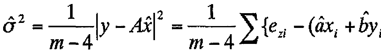
- the following relational expression holds between the measured value of the spatial error and the unknown parameter (a, b, c, d).
- the estimated value of ⁇ 2 is + + ⁇ 2 and using this estimate, the covariance matrix Cx of the uncertainty of the least squares solution is
- the fitting is performed by using every other measurement point for which an error has been obtained by the sequential two-point method, and the error at the remaining measurement points is calculated.
- the error obtained by the calculation is compared with the error obtained by the sequential two-point method. If the two values are sufficiently close, the error correction method can be considered valid. At the same time, it is thought that it is possible to estimate the magnitude of the error of the value corrected by the error correction method from the difference between the two values at that time.
- This fusion method can be used, for example, to fuse measurement results in the X-axis and y-axis directions, measurement results in the positive direction and measurement results in the negative direction, and multiple measurement results using the same method.
- the feature of the method of the present invention is that, since the equipment used is simple and the processing is easy, the error space is re-evaluated in response to the time fluctuation of the measurement equipment. Is simple.
- the present invention provides a technique for measuring the shape of a machined part such as a machine part, and information that enables an improvement in measurement performance by expressing an error space as a matrix and constructing a correction relational expression based on the matrix.
- Various technical fields such as processing technology, production processing technology that enables the production of high-precision machine parts that satisfy this with improved accuracy, and production processing technology that can be applied to tool movement of machine tools Benefits.
Landscapes
- Engineering & Computer Science (AREA)
- Physics & Mathematics (AREA)
- Chemical & Material Sciences (AREA)
- General Physics & Mathematics (AREA)
- Mechanical Engineering (AREA)
- Nanotechnology (AREA)
- Robotics (AREA)
- General Health & Medical Sciences (AREA)
- Molecular Biology (AREA)
- Life Sciences & Earth Sciences (AREA)
- Crystallography & Structural Chemistry (AREA)
- Health & Medical Sciences (AREA)
- Optics & Photonics (AREA)
- Length Measuring Devices With Unspecified Measuring Means (AREA)
- Automatic Control Of Machine Tools (AREA)
- Machine Tool Sensing Apparatuses (AREA)
Description


Claims
Priority Applications (3)
| Application Number | Priority Date | Filing Date | Title |
|---|---|---|---|
| US10/110,740 US6694634B2 (en) | 2000-08-18 | 2001-01-22 | Position error evaluation method of moving device and method of improving movement accuracy based on evaluation results thereof |
| EP01901499A EP1219924B1 (en) | 2000-08-18 | 2001-01-22 | Positional error evaluation method for mobile device and movement accuracy improving method based on the evaluation result |
| DE60126900T DE60126900T2 (de) | 2000-08-18 | 2001-01-22 | Verfahren zur evaluation einer fehlerposition für ein bewegliches objekt und verbesserung der bewegungsgenauigkeit auf grundlage des gefundenen resultates |
Applications Claiming Priority (2)
| Application Number | Priority Date | Filing Date | Title |
|---|---|---|---|
| JP2000248784A JP4660779B2 (ja) | 2000-08-18 | 2000-08-18 | 移動装置の位置誤差評価方法およびその評価結果に基づく移動精度向上方法 |
| JP2000/248784 | 2000-08-18 |
Publications (1)
| Publication Number | Publication Date |
|---|---|
| WO2002016868A1 true WO2002016868A1 (en) | 2002-02-28 |
Family
ID=18738628
Family Applications (1)
| Application Number | Title | Priority Date | Filing Date |
|---|---|---|---|
| PCT/JP2001/000390 Ceased WO2002016868A1 (en) | 2000-08-18 | 2001-01-22 | Positional error evaluation method for mobile device and movement accuracy improving method based on the evaluation result |
Country Status (6)
| Country | Link |
|---|---|
| US (1) | US6694634B2 (ja) |
| EP (1) | EP1219924B1 (ja) |
| JP (1) | JP4660779B2 (ja) |
| CN (1) | CN1189721C (ja) |
| DE (1) | DE60126900T2 (ja) |
| WO (1) | WO2002016868A1 (ja) |
Cited By (2)
| Publication number | Priority date | Publication date | Assignee | Title |
|---|---|---|---|---|
| CN100419371C (zh) * | 2003-11-25 | 2008-09-17 | 株式会社三丰 | 表面仿形测量装置和仿形测头的修正表制作方法 |
| CN109596898A (zh) * | 2018-12-18 | 2019-04-09 | 北京无线电计量测试研究所 | 一种探头支撑装置和同心锥形tem室 |
Families Citing this family (44)
| Publication number | Priority date | Publication date | Assignee | Title |
|---|---|---|---|---|
| JP4660779B2 (ja) * | 2000-08-18 | 2011-03-30 | 学校法人 中央大学 | 移動装置の位置誤差評価方法およびその評価結果に基づく移動精度向上方法 |
| WO2002101323A2 (en) * | 2001-06-12 | 2002-12-19 | Hexagon Metrology Ab | A communication method and common control bus interconnecting a controller and a precision measurement assembly |
| US7317992B2 (en) * | 2004-06-16 | 2008-01-08 | General Electric Company | Method and apparatus for inspecting dovetail edgebreak contour |
| SE527899C2 (sv) * | 2004-12-15 | 2006-07-04 | Hexagon Metrology Ab | Koordinatmätmaskin med inbördes förflyttbara ben |
| JP4694881B2 (ja) * | 2005-01-05 | 2011-06-08 | 株式会社ミツトヨ | 不確かさ推定方法及びプログラム |
| JP4717639B2 (ja) * | 2006-01-06 | 2011-07-06 | 東芝機械株式会社 | 基板の両面形状測定方法及び装置 |
| US8506214B2 (en) * | 2006-02-10 | 2013-08-13 | Klingelnberg Gmbh | Method for machining bevel gears using an indexing method having complete indexing error compensation |
| JP4875409B2 (ja) * | 2006-06-06 | 2012-02-15 | 株式会社岡本工作機械製作所 | 被平面研削加工物の平面研削方法 |
| KR20060100307A (ko) * | 2006-08-08 | 2006-09-20 | 주식회사 거성기업 | 3차원 입체영상 재현용 전하결합소자 (3D imaging CCD) |
| GB0707921D0 (en) * | 2007-04-24 | 2007-05-30 | Renishaw Plc | Apparatus and method for surface measurement |
| US8250772B2 (en) * | 2008-02-07 | 2012-08-28 | Eaton Homer L | Spatial measurement and robotic arm device |
| JP5192283B2 (ja) * | 2008-05-13 | 2013-05-08 | 株式会社ミツトヨ | 三次元測定機 |
| JP5684712B2 (ja) * | 2008-10-29 | 2015-03-18 | レニショウ パブリック リミテッド カンパニーRenishaw Public Limited Company | 座標測定システムのための方法 |
| KR101128913B1 (ko) * | 2009-05-07 | 2012-03-27 | 에스엔유 프리시젼 주식회사 | 비전 검사시스템 및 이를 이용한 좌표변환방법 |
| JP5272248B2 (ja) * | 2009-05-08 | 2013-08-28 | 株式会社ミツトヨ | 表面性状測定装置、表面性状測定方法、及びプログラム |
| US20100299094A1 (en) * | 2009-05-23 | 2010-11-25 | Carmar Technology Co., Ltd. | Thermal deformation error compensation method for coordinate measuring machine |
| JP5330297B2 (ja) * | 2009-05-26 | 2013-10-30 | 株式会社ミツトヨ | アライメント調整機構、および測定装置 |
| EP2385339A1 (en) * | 2010-05-05 | 2011-11-09 | Leica Geosystems AG | Surface sensing device with optical monitoring system |
| US10041790B2 (en) * | 2012-03-07 | 2018-08-07 | Nippon Steel & Sumitomo Metal Corporation | Misalignment calculation system |
| EP2839240B1 (en) | 2012-04-18 | 2017-09-06 | Renishaw PLC | A method of analogue measurement scanning on a machine tool and corresponding machine tool apparatus |
| EP2839241B1 (en) | 2012-04-18 | 2018-08-08 | Renishaw PLC | Method of finding a feature of an object using a machine tool and corresponding machine tool apparatus |
| US10037017B2 (en) | 2012-04-18 | 2018-07-31 | Renishaw Plc | Method of measurement on a machine tool and corresponding machine tool apparatus |
| CN102929007B (zh) * | 2012-10-19 | 2015-06-03 | 深圳市华星光电技术有限公司 | 测量设备及其控制方法 |
| CN104325467B (zh) * | 2014-11-05 | 2016-01-20 | 南京熊猫电子股份有限公司 | 机器人运动精度测试装置 |
| JP6481477B2 (ja) * | 2015-04-16 | 2019-03-13 | 日本精工株式会社 | ワークの自動芯出し装置、該自動芯出し装置に使用される可動装置の位置決め方法、生産機械、及び軸受の製造方法 |
| JP2018194430A (ja) * | 2017-05-17 | 2018-12-06 | 株式会社ミツトヨ | ステップゲージ |
| CN107966126B (zh) * | 2017-12-05 | 2019-10-29 | 玉环普天单向器有限公司 | 一种星轮曲面及曲面锥度的测量方法 |
| JP7045194B2 (ja) * | 2018-01-11 | 2022-03-31 | 株式会社ミツトヨ | レンズ測定装置およびレンズ測定方法 |
| JP6683749B2 (ja) * | 2018-03-14 | 2020-04-22 | ファナック株式会社 | 補正量取得装置、送り機構制御装置、補正量取得方法および送り機構の制御方法 |
| CN108759657B (zh) * | 2018-06-15 | 2021-08-06 | 哈尔滨工业大学 | 一种感应同步器角度自动化检测装置与方法 |
| JP6796774B2 (ja) * | 2018-07-02 | 2020-12-09 | パナソニックIpマネジメント株式会社 | 平面度校正方法及び装置 |
| CN109397293B (zh) * | 2018-11-27 | 2022-05-31 | 上海机器人产业技术研究院有限公司 | 一种基于移动机器人的地面水平误差建模及补偿方法 |
| CN109760107B (zh) * | 2019-01-22 | 2022-04-12 | 九天创新(广东)智能科技有限公司 | 一种基于单目视觉的机器人定位精度评价方法 |
| CN109732613B (zh) * | 2019-03-13 | 2023-08-18 | 哈尔滨市伟晨星知识产权法律服务有限公司 | 机械手臂达到特定状态效果评估系统 |
| CN110977612B (zh) * | 2019-11-18 | 2021-08-03 | 上海爱堃智能系统有限公司 | Cnc数控加工在线测量误差修正方法及系统 |
| CN111874646A (zh) * | 2020-08-11 | 2020-11-03 | 界首市鸿鑫塑业有限公司 | 一种塑料型材用码垛机及其码垛方法 |
| CN115194749B (zh) * | 2021-04-09 | 2025-03-14 | 库卡机器人制造(上海)有限公司 | 加工设备的控制方法、加工设备和可读存储介质 |
| CN113701687B (zh) * | 2021-09-17 | 2023-07-21 | 中国联合网络通信集团有限公司 | 空间曲线长度测量系统及测量方法 |
| CN114184151B (zh) * | 2021-12-15 | 2024-01-02 | 上海无线电设备研究所 | 一种单轴坐标外推方法 |
| CN115035196A (zh) * | 2022-04-18 | 2022-09-09 | 哈尔滨理工大学 | 一种基于弯制点复杂度判断的正畸弓丝误差率评价方法 |
| WO2024048647A1 (ja) * | 2022-08-31 | 2024-03-07 | 株式会社ワコム | 電子ペンの評価方法及び評価システム |
| CN115847189A (zh) * | 2022-11-11 | 2023-03-28 | 福建工程学院 | 一种基于激光干涉仪测量的多轴机床几何误差辨识方法 |
| CN115990886B (zh) * | 2023-03-03 | 2025-01-24 | 北京航空航天大学 | 一种用于机器人在线误差补偿的误差预测方法 |
| CN117128912B (zh) * | 2023-10-26 | 2024-01-12 | 深圳市博铭维技术股份有限公司 | 管道内径测量装置及其测量方法 |
Citations (2)
| Publication number | Priority date | Publication date | Assignee | Title |
|---|---|---|---|---|
| JPH0510751A (ja) * | 1991-07-03 | 1993-01-19 | Mitsutoyo Corp | 測定値評価方式 |
| JPH109852A (ja) * | 1996-06-20 | 1998-01-16 | Nikon Corp | 真直度測定方法 |
Family Cites Families (15)
| Publication number | Priority date | Publication date | Assignee | Title |
|---|---|---|---|---|
| US3875667A (en) * | 1973-11-21 | 1975-04-08 | Handy & Herman Specialty Metal | In-line straightness sensing device |
| US4945501A (en) * | 1987-01-20 | 1990-07-31 | The Warner & Swasey Company | Method for determining position within the measuring volume of a coordinate measuring machine and the like and system therefor |
| US4939678A (en) * | 1987-11-19 | 1990-07-03 | Brown & Sharpe Manufacturing Company | Method for calibration of coordinate measuring machine |
| JPH07146125A (ja) * | 1993-11-26 | 1995-06-06 | Hitachi Zosen Corp | 真直度測定装置 |
| JPH07334245A (ja) * | 1994-06-13 | 1995-12-22 | Yotaro Hatamura | 超精密送り装置およびこれを用いたxyテ−ブル並びにテ−ブル移送装置 |
| US5687487A (en) * | 1995-09-25 | 1997-11-18 | Dogwood Restorations | Flatness tester |
| GB2306654A (en) * | 1995-10-31 | 1997-05-07 | Rank Taylor Hobson Ltd | Surface measuring apparatus |
| JP2983941B2 (ja) * | 1997-11-11 | 1999-11-29 | 川崎重工業株式会社 | 3次元自動計測装置用計測誤差補正方法 |
| KR100264247B1 (ko) * | 1998-03-28 | 2000-08-16 | 김영삼 | 공작기계의 열변형오차 측정 및 보정시스템 |
| GB9907868D0 (en) * | 1999-04-08 | 1999-06-02 | Renishaw Plc | Method of calibrating a scanning system |
| JP2001041733A (ja) * | 1999-07-30 | 2001-02-16 | Univ Chuo | 表面形状計測装置 |
| US6546640B2 (en) * | 2000-01-18 | 2003-04-15 | Mitutoyo Corporation | Traverse linearity compensation method and rotational accuracy compensation method of measuring device |
| JP2001330428A (ja) * | 2000-05-23 | 2001-11-30 | Natl Inst Of Advanced Industrial Science & Technology Meti | 3次元測定機の測定誤差評価方法及び3次元測定機用ゲージ |
| JP4660779B2 (ja) * | 2000-08-18 | 2011-03-30 | 学校法人 中央大学 | 移動装置の位置誤差評価方法およびその評価結果に基づく移動精度向上方法 |
| US6487787B1 (en) * | 2001-08-03 | 2002-12-03 | Mitutoyo Corporation | System and method for determination of error parameters for performing self-calibration and other functions without an external position reference in a transducer |
-
2000
- 2000-08-18 JP JP2000248784A patent/JP4660779B2/ja not_active Expired - Fee Related
-
2001
- 2001-01-22 CN CNB018027814A patent/CN1189721C/zh not_active Expired - Fee Related
- 2001-01-22 US US10/110,740 patent/US6694634B2/en not_active Expired - Fee Related
- 2001-01-22 WO PCT/JP2001/000390 patent/WO2002016868A1/ja not_active Ceased
- 2001-01-22 DE DE60126900T patent/DE60126900T2/de not_active Expired - Lifetime
- 2001-01-22 EP EP01901499A patent/EP1219924B1/en not_active Expired - Lifetime
Patent Citations (2)
| Publication number | Priority date | Publication date | Assignee | Title |
|---|---|---|---|---|
| JPH0510751A (ja) * | 1991-07-03 | 1993-01-19 | Mitsutoyo Corp | 測定値評価方式 |
| JPH109852A (ja) * | 1996-06-20 | 1998-01-16 | Nikon Corp | 真直度測定方法 |
Non-Patent Citations (1)
| Title |
|---|
| See also references of EP1219924A4 * |
Cited By (2)
| Publication number | Priority date | Publication date | Assignee | Title |
|---|---|---|---|---|
| CN100419371C (zh) * | 2003-11-25 | 2008-09-17 | 株式会社三丰 | 表面仿形测量装置和仿形测头的修正表制作方法 |
| CN109596898A (zh) * | 2018-12-18 | 2019-04-09 | 北京无线电计量测试研究所 | 一种探头支撑装置和同心锥形tem室 |
Also Published As
| Publication number | Publication date |
|---|---|
| EP1219924A1 (en) | 2002-07-03 |
| EP1219924B1 (en) | 2007-02-28 |
| EP1219924A4 (en) | 2006-07-26 |
| JP4660779B2 (ja) | 2011-03-30 |
| US6694634B2 (en) | 2004-02-24 |
| JP2002059340A (ja) | 2002-02-26 |
| CN1189721C (zh) | 2005-02-16 |
| CN1392950A (zh) | 2003-01-22 |
| US20030019119A1 (en) | 2003-01-30 |
| DE60126900D1 (de) | 2007-04-12 |
| DE60126900T2 (de) | 2007-12-06 |
Similar Documents
| Publication | Publication Date | Title |
|---|---|---|
| WO2002016868A1 (en) | Positional error evaluation method for mobile device and movement accuracy improving method based on the evaluation result | |
| US7900367B2 (en) | Differential calibration | |
| CN107570983B (zh) | 一种曲面零件自动装配的方法及系统 | |
| CN109870111A (zh) | 基于机器视觉的渐开线圆柱齿轮齿距累积误差测量方法 | |
| CN112325773B (zh) | 一种激光位移传感器的光束方向矢量和原点位置标定方法 | |
| US12607443B2 (en) | Method for calculating compensation parameter of motion error in machine tool, and machine tool | |
| CN107063060A (zh) | 一种确定表面平面度的方法及装置 | |
| Wu et al. | A novel calibration method for non-orthogonal shaft laser theodolite measurement system | |
| JP2003114117A (ja) | プローブの校正方法および校正プログラム | |
| JP7158582B2 (ja) | 調整量推定装置、調整量推定方法、調整量推定プログラム及び工作機械組立方法 | |
| CN111046584B (zh) | 星载仪器设备的精密调整方法 | |
| CN106796095B (zh) | 操作坐标测量设备的方法、坐标测量设备和计算机程序 | |
| KR102035334B1 (ko) | 4축 공작기계의 기하학적 오차 측정 방법 | |
| CN115383405A (zh) | 一种多边形钢塔加工质量控制工艺 | |
| JP7701195B2 (ja) | プローブユニットの補正方法 | |
| CN114034244B (zh) | 一种基于Makima算法获得CMM测量范围内任意点几何误差的方法 | |
| KR101525677B1 (ko) | 원호 시험용 가상 오차 평가 시뮬레이션 방법 | |
| JP4634657B2 (ja) | 表面性状測定装置の校正方法 | |
| JP2008524576A (ja) | 直定規の直線度測定のための順次式マルチプローブ法 | |
| Freeman et al. | A novel use of artefacts in non-Cartesian machine calibration | |
| Khan et al. | Squareness perpendicularity measuring techniques in multiaxis machine tools | |
| CN116202456A (zh) | 基于非线性插值算法的三坐标测量机定位误差补偿方法 | |
| Gąska et al. | Determination of coordinate measuring machines accuracy changes made by different nodes density in CAA matrix | |
| Swornowski | The delimitation of the workspace accuracy in coordinate measuring technique | |
| FORBES | National Physical Laboratory, Teddington, UK, TW11 0LW Email: alistair. forbes@ npl. co. uk, ian. smith@ npl. co. uk |
Legal Events
| Date | Code | Title | Description |
|---|---|---|---|
| AK | Designated states |
Kind code of ref document: A1 Designated state(s): CN US |
|
| AL | Designated countries for regional patents |
Kind code of ref document: A1 Designated state(s): AT BE CH CY DE DK ES FI FR GB GR IE IT LU MC NL PT SE TR |
|
| 121 | Ep: the epo has been informed by wipo that ep was designated in this application | ||
| WWE | Wipo information: entry into national phase |
Ref document number: 2001901499 Country of ref document: EP |
|
| WWE | Wipo information: entry into national phase |
Ref document number: 018027814 Country of ref document: CN |
|
| WWP | Wipo information: published in national office |
Ref document number: 2001901499 Country of ref document: EP |
|
| WWE | Wipo information: entry into national phase |
Ref document number: 10110740 Country of ref document: US |
|
| WWG | Wipo information: grant in national office |
Ref document number: 2001901499 Country of ref document: EP |