WO2004015428A2 - Combined speed and depth transducer for marine applications - Google Patents
Combined speed and depth transducer for marine applications Download PDFInfo
- Publication number
- WO2004015428A2 WO2004015428A2 PCT/US2003/024301 US0324301W WO2004015428A2 WO 2004015428 A2 WO2004015428 A2 WO 2004015428A2 US 0324301 W US0324301 W US 0324301W WO 2004015428 A2 WO2004015428 A2 WO 2004015428A2
- Authority
- WO
- WIPO (PCT)
- Prior art keywords
- sensor
- transducer
- housing
- vessel
- inches
- Prior art date
- Legal status (The legal status is an assumption and is not a legal conclusion. Google has not performed a legal analysis and makes no representation as to the accuracy of the status listed.)
- Ceased
Links
Classifications
-
- G—PHYSICS
- G01—MEASURING; TESTING
- G01S—RADIO DIRECTION-FINDING; RADIO NAVIGATION; DETERMINING DISTANCE OR VELOCITY BY USE OF RADIO WAVES; LOCATING OR PRESENCE-DETECTING BY USE OF THE REFLECTION OR RERADIATION OF RADIO WAVES; ANALOGOUS ARRANGEMENTS USING OTHER WAVES
- G01S7/00—Details of systems according to groups G01S13/00, G01S15/00, G01S17/00
- G01S7/52—Details of systems according to groups G01S13/00, G01S15/00, G01S17/00 of systems according to group G01S15/00
- G01S7/521—Constructional features
-
- G—PHYSICS
- G01—MEASURING; TESTING
- G01P—MEASURING LINEAR OR ANGULAR SPEED, ACCELERATION, DECELERATION, OR SHOCK; INDICATING PRESENCE, ABSENCE, OR DIRECTION, OF MOVEMENT
- G01P1/00—Details of instruments
- G01P1/02—Housings
-
- G—PHYSICS
- G01—MEASURING; TESTING
- G01C—MEASURING DISTANCES, LEVELS OR BEARINGS; SURVEYING; NAVIGATION; GYROSCOPIC INSTRUMENTS; PHOTOGRAMMETRY OR VIDEOGRAMMETRY
- G01C13/00—Surveying specially adapted to open water, e.g. sea, lake, river or canal
- G01C13/008—Surveying specially adapted to open water, e.g. sea, lake, river or canal measuring depth of open water
-
- G—PHYSICS
- G01—MEASURING; TESTING
- G01P—MEASURING LINEAR OR ANGULAR SPEED, ACCELERATION, DECELERATION, OR SHOCK; INDICATING PRESENCE, ABSENCE, OR DIRECTION, OF MOVEMENT
- G01P5/00—Measuring speed of fluids, e.g. of air stream; Measuring speed of bodies relative to fluids, e.g. of ship, of aircraft
- G01P5/02—Measuring speed of fluids, e.g. of air stream; Measuring speed of bodies relative to fluids, e.g. of ship, of aircraft by measuring forces exerted by the fluid on solid bodies, e.g. anemometer
- G01P5/06—Measuring speed of fluids, e.g. of air stream; Measuring speed of bodies relative to fluids, e.g. of ship, of aircraft by measuring forces exerted by the fluid on solid bodies, e.g. anemometer using rotation of vanes
-
- G—PHYSICS
- G01—MEASURING; TESTING
- G01P—MEASURING LINEAR OR ANGULAR SPEED, ACCELERATION, DECELERATION, OR SHOCK; INDICATING PRESENCE, ABSENCE, OR DIRECTION, OF MOVEMENT
- G01P5/00—Measuring speed of fluids, e.g. of air stream; Measuring speed of bodies relative to fluids, e.g. of ship, of aircraft
- G01P5/02—Measuring speed of fluids, e.g. of air stream; Measuring speed of bodies relative to fluids, e.g. of ship, of aircraft by measuring forces exerted by the fluid on solid bodies, e.g. anemometer
- G01P5/06—Measuring speed of fluids, e.g. of air stream; Measuring speed of bodies relative to fluids, e.g. of ship, of aircraft by measuring forces exerted by the fluid on solid bodies, e.g. anemometer using rotation of vanes
- G01P5/07—Measuring speed of fluids, e.g. of air stream; Measuring speed of bodies relative to fluids, e.g. of ship, of aircraft by measuring forces exerted by the fluid on solid bodies, e.g. anemometer using rotation of vanes with electrical coupling to the indicating device
-
- G—PHYSICS
- G01—MEASURING; TESTING
- G01S—RADIO DIRECTION-FINDING; RADIO NAVIGATION; DETERMINING DISTANCE OR VELOCITY BY USE OF RADIO WAVES; LOCATING OR PRESENCE-DETECTING BY USE OF THE REFLECTION OR RERADIATION OF RADIO WAVES; ANALOGOUS ARRANGEMENTS USING OTHER WAVES
- G01S15/00—Systems using the reflection or reradiation of acoustic waves, e.g. sonar systems
- G01S15/02—Systems using the reflection or reradiation of acoustic waves, e.g. sonar systems using reflection of acoustic waves
- G01S15/06—Systems determining the position data of a target
- G01S15/08—Systems for measuring distance only
-
- G—PHYSICS
- G10—MUSICAL INSTRUMENTS; ACOUSTICS
- G10K—SOUND-PRODUCING DEVICES; METHODS OR DEVICES FOR PROTECTING AGAINST, OR FOR DAMPING, NOISE OR OTHER ACOUSTIC WAVES IN GENERAL; ACOUSTICS NOT OTHERWISE PROVIDED FOR
- G10K11/00—Methods or devices for transmitting, conducting or directing sound in general; Methods or devices for protecting against, or for damping, noise or other acoustic waves in general
-
- G—PHYSICS
- G10—MUSICAL INSTRUMENTS; ACOUSTICS
- G10K—SOUND-PRODUCING DEVICES; METHODS OR DEVICES FOR PROTECTING AGAINST, OR FOR DAMPING, NOISE OR OTHER ACOUSTIC WAVES IN GENERAL; ACOUSTICS NOT OTHERWISE PROVIDED FOR
- G10K11/00—Methods or devices for transmitting, conducting or directing sound in general; Methods or devices for protecting against, or for damping, noise or other acoustic waves in general
- G10K11/004—Mounting transducers, e.g. provided with mechanical moving or orienting device
- G10K11/006—Transducer mounting in underwater equipment, e.g. sonobuoys
-
- B—PERFORMING OPERATIONS; TRANSPORTING
- B63—SHIPS OR OTHER WATERBORNE VESSELS; RELATED EQUIPMENT
- B63B—SHIPS OR OTHER WATERBORNE VESSELS; EQUIPMENT FOR SHIPPING
- B63B49/00—Arrangements of nautical instruments or navigational aids
Definitions
- Certain depth measuring devices employ an ultrasonic transducer that emits an acoustic beam downwardly from the boat. When the beam strikes something, such as the bottom, the beam reflects an echo back to the transducer. This is converted into electrical energy, amplified and displayed as information on a screen. The information can be displayed on a paper graph, flashing device, or video display.
- speed, depth, and temperature measuring instruments were three separate devices that required drilling three holes in the hull.
- these measuring sensors have been combined into a single instrument which provides information with respect to all three parameters of speed, temperature, and depth.
- these single instruments do not allow the sensors to be readily removable from within the hull.
- the depth sensor cannot be removed while the vessel is afloat because the size of the transducer element is greater than the opening in the hull.
- a marine sensor device mounts in a single opening in a hull of a marine vessel.
- the sensor includes a housing secured in the opening.
- a body Positioned within the housing is a body containing at least two sensors.
- the body is removable from the housing.
- a magnetized paddlewheel can be disposed in a first cavity formed on a first half of the body, the paddlewheel has a plurality of paddles extending from a circular central hub and rotatably mounted on an axle extending transverse a fore and aft direction of travel of the vessel.
- a magnetic sensor can be located adjacent the paddles, the magnetic sensor senses the rotation of the paddles and provides speed indications.
- the magnetic sensor can be a Hall-effect device.
- a sonic transducer for depth detection can be disposed within a second cavity formed on a second half of the body.
- a thermal sensor for sensing water temperature can be disposed in a well formed in the body.
- the cross-sectional area of the paddles in a plane transverse a direction of flow of water being traversed by the marine vessel and in a plane parallel the direction of flow versus the available cross sectional area in the respective planes define a Cross-Sectional ratio having a range between about 0.25 and 0.5.
- the lowest point on the periphery of the hub can be located tangentially adjacent to or vertically above the lowest point in the first cavity. It is important to maintain the Cross-Sectional ratio is preferably maintained between 0.25 and 0.5 to reduce the build-up of negative cavity pressure and thus minimize the tendency to cavitate within the cavity at high speeds.
- the Cross-Sectional ratio in the plane parallel to the direction of flow is different than the Cross-Sectional ratio in the plane transverse the direction of flow, h other embodiments, the Cross-Sectional ratio in the plane parallel to the direction of flow is about equal the Cross-Sectional ratio in the plane transverse the direction of flow.
- the first cavity can be an asymmetric cavity
- the transducer can be a piezoelectric element having an aspect ratio defined in terms of the length, width, and height of the piezoelectric element.
- the aspect ratio being optimized such that the maximum acoustic energy of the element is produced when the element vibrates with a frequency of about 150 kHz to about 250 kHz.
- the maximum acoustic energy of the piezoelectric element is produced when the element vibrates with a frequency of about 235 kHz.
- the piezoelectric element can be made of PZT.
- the length of the piezoelectric element can be about 1.0 to 1.3 inches in length, about 0.1 to 0.5 inches in height, and about 0.1 to 0.5 inches in width.
- the length of the piezoelectric element can be about 1.25 inches, the height is about 0.23 inch, and the width is about 0.22 inch.
- the transducer can have a beamwidth of about 11° x 38° at about -3dB.
- the sensor body is disposed in a housing that fits into a single circular opening through a hull of the vessel.
- the housing contained at least two removable sensors, a speed sensor and a depth sensor.
- a temperature sensor may be disposed in the housing.
- FIG. 1 is a perspective view of a high speed through-hull speed sensor of one embodiment of the invention.
- FIG. 2 is a front view of the sensor of FIG. 1.
- FIG. 2A is a top view of the sensor along the line 2A-2A of FIG. 2.
- FIG. 2B is a bottom view of the sensor along the line 2B-2B of FIG.2
- FIG. 2C is a side view of the sensor along the line 2C-2C of FIG. 2.
- FIG. 3 is an exploded view of the sensor of FIG. 1.
- FIG. 4 is a perspective view of an inner tubular body of the sensor of FIG. 1.
- FIG. 5 is a front view of the tubular body of FIG. 4.
- FIG. 5 A is a top view of the tubular body along the line 5A-5A of FIG. 5.
- FIG. 5B is a bottom view of the tubular body along the line 5B-5B of FIG. 5.
- FIG. 5Ba is another bottom view of the tubular body illustrating the cross sectional area of a cavity of the body as occupied by a paddle of a paddlewheel speed sensor.
- FIG. 5Bb is a detailed view of the cross sectional area of the cavity identified in FIG. 5Ba as occupied by the paddle.
- FIG. 5Bc is a detailed view of the cross sectional area of the cavity identified in FIG. 5Ba when not occupied by the paddle.
- FIG. 5C is a side view of the tubular body.
- FIG. 5D is a partial cutaway side view of the tubular body shown as shown in
- FIG. 5C the partial view being taken along the line 5D-5D with the paddlewheel fully shown illustrating the cross sectional area of the cavity of the body as occupied by a paddle of a paddlewheel speed sensor.
- FIG. 5Da is a detailed view of the cross sectional area of the cavity identified in FIG. 5D as occupied by the paddle.
- FIG. 5Db is a detailed view of the cross sectional area of the cavity identified in FIG. 5D when not occupied by the paddle.
- FIG. 6 is an exploded view of the tubular body of FIG. 4.
- FIG. 6 A is a detailed view of a support board and a lower tube portion of the tubular body of FIG. 4
- FIG. 7 is a perspective view of the sensor with a single center skeg in accordance with the invention.
- FIG. 8 is a perspective view of the sensor with no skeg in accordance with the invention.
- FIG. 9 is a perspective view of the sensor with two outer skegs in accordance with the invention.
- FIG. 10 is a perspective view of the sensor with a center and two outer skegs in accordance with the invention.
- FIG. 11 is a perspective view of the ultrasonic transducer of the sensor of FIG. 1.
- FIG. 12 is a plot of the athwartships beam pattern of the transducer of FIG. 11.
- FIG. 13 is a plot of the fore aft beam pattern of the transducer of FIG.11.
- FIG. 14 is a perspective view of the ultrasonic transducer of the sensor of FIG. 1 with dimensions.
- FIG. 15A is a 3-dimensional displacement map exhibiting a "good” coupling mode.
- FIG. 15B is a 3-dimensional displacement map exhibiting a "poor" coupling mode.
- the device 10 can be mounted tl rough a hull of the marine vessel.
- the device 10 has a housing designated, generally, by the numeral 12, the housing 12 having a vertically extending threaded cylinder 12S, and lower flared portion 12L, respectively.
- the illustrated sensor device 10 is shown by way of example only. The invention is not limited for use in such a device, the present invention can be used in any other suitable sensor device, such as, for example, a transom mounted sensor.
- the threaded cylinder 12S is positioned in an opening through the hull.
- the hull is wedged between the hull nut 13 and the flared portion 12L.
- a tubular body 52 having an upper portion 52a and a lower portion 52b, the lower portion 52b forming an asymmetric paddlewheel cavity 30.
- the paddlewheel cavity 30 is positioned on one side of the lower portion 52b of the body and is considered to be asymmetric as contrasted to the paddlewheel cavity of prior art devices which used the entire lower portion of the circular tube.
- the body 52 is adapted to slide into the threaded cylinder 12S.
- O- rings 32 and 34, respectively, are positioned in grooves on the periphery of the body 52 and form a fluid-tight seal between the body 52 and threaded cylinder 12S.
- the body 52 is of tubular shape and is formed of metal or plastic.
- a cable 16 containing wires 19 (FIGS. 1 and 6) is coupled tlirough a bored hole 27 formed in an enlarged wall of the threaded cylinder 12S.
- the wires 19 provide electrical connection to components, such as a Hall-effect device 56, a transducer 60, and a thermistor 62 (FIG. 5C), each of which are positioned within the lower tube portion 52b.
- a paddlewheel 26 is mounted on axle 28 within the asymmetric cavity 30 formed in the lower tube portion 52b.
- the paddlewheel 26 is an integral structure having a hub 38 from which four symmetric shaped paddles 42 extend about the periphery thereof.
- the axle 28 rotates within bearings 37 disposed in a bore 39 which extends through a central opening in the hub 38, and into opposing recessed holes in the cavity side walls formed in the lower tube portion 52b.
- the paddlewheel 26 is thereby rotatably suspended within the cavity 30.
- the paddlewheel 26 is formed of amorphous magnetized material, such as barium ferrite.
- the paddles 42 can be polarized with respect to the hub 38, or with respect to each other. As the paddles 42 rotate about the axle 28 when the vessel traverses the water, the variation in magnetic field is sensed by the Hall-effect device 56 mounted on a support board 57 positioned in the lower tube portion 52b.
- the flared portion 12L is mounted flush against the outer surface of the hull to prevent impact with objects as the marine vessel moves through the water.
- a skeg 15 extends from the lower tube portion 52b of the body 52 to straighten the flow of water past the paddlewheel 26, for example, when the vessel, such as sail boat heels over as it moves through the water.
- the tubular body 52 in some embodiments is constructed of material that is permeable to the magnetic field emanating from the paddlewheel.
- the thermal sensing device 62 and Hall-effect device 56 can be of the types as described in U.S. Pat. No. 4,555,938, the entire contents of which are incorporated herein by reference, and are electrically coupled respectively via wires 19 to a temperature display 80 and a speed display 70 by way of terminals 100a and 100b extending from the board 57 (see, in particular, FIGS. 1, 3, 6, and 6A).
- the thermal sensing device 62 and the Hall-effect device 56 are contained within the lower tube portion 52b of the tubular body 52.
- the thermal sensing device 62 extends from the board 57 and is positioned within a well 62w (FIG. 6A) of the lower tube portion 52b.
- the upper wall 44 (FIGS. 3 and 6) of cavity 30 is an arched surface, closely spaced from the tip T of the four paddles 42 as they rotate about axle 28.
- the periphery P of the hub 38 is approximately flush with the bottom surface B of the cavity.
- the cross- sectional shape 80 of the paddles 42 in the present embodiment is changed from the above-referenced art.
- the cross-sectional shape taken in a plane parallel the direction of flow versus the available cross-sectioned space 82 in the cavity 30 in the same plane, i.e., Cross-Sectional Ratio is preferably and optionally between about 0.25 to 0.5. This ratio is in the order of 0.30. This ratio is achieved by using a relatively thin cross-sectional paddle and by symmetrically rounding off the side walls Z of the paddles at the tips and symmetrically removing material from the sidewalls as they join the hub. This reduces the numerator of the ratio, i.e., paddle cross-section.
- the cavity 30 has an asymmetric shape, which results from positioning the paddlewheel 26 off-center relative to a center plane 84 extending along the length of the tubular body 52, that is, extending into the page.
- This arrangement as well as the small size of the transducer 60 has the particular advantage of placing the transducer 60, thermal sensing 62, and Hall-effect device 56, as well as the paddlewheel 26, all within a single structure, namely, the tubular body 52, and more particularly, the lower portion 52b of the tubular body 52.
- the Cross-Sectional Ratio may vary within the cavity 30, as illustrated in FIGS. 5D, 5Da, and 5Db.
- the cross-sectional shape 80 of the paddles 42 is the same when taken in a plane transverse the direction of flow (FIG. 5Da)
- the available cross-sectioned space 92 (FIG. 5Db) in the cavity in the same plane can be different than the available cross-sectioned space 82 shown in FIG. 5Bc.
- the Cross-Sectional Ratio for the plane of FIG. 5D is about 0.34.
- the Cross-Sectional Ratio is. the same for both planes, even though the shape of the cross-sectioned shapes 82 and 92 are different.
- FIGS. 8-10 show alternate embodiments of the device discussed above. Recall that a single skeg 15 was positioned at the center of lower portion 12L of the sleeve 12 (shown again in FIG. 7 for reference). However, there can be more than one skeg located at different positions on the lower portion 12L. For example, as shown in FIG. 9, there are a pair of parallel skegs 15a and 15b located near respective outer regions of the lower portion 12L. These can also be combined with the center skeg 15 as shown in FIG. 10. Optionally, in some implementations, the device 10 does not include a skeg as illustrated in FIG. 8.
- the transducer 60 is formed of a piezoelectric element 102 coated with an upper and lower layer of silver 104, 106 that provides an electrical connection with terminals 100a and 100b on board 57 (FIGS. 3, 6) to an electronic driver assembly 90 (FIG. 1) associated with a depth indicator 90 (FIG. 1).
- the transducer 60 is made to fit within the lower tube portion 52b of the body 52 such that the body can be removed from the housing 12 while the vessel is afloat.
- the piezoelectric element 102 is enclosed in a resilient backing member 61 (FIGS. 3, 6), preferably consisting of cork material or an equivalent material.
- the backing member 61 encloses the piezoelectric element 102 at the top and sides of the generally rectangular piezoelectric crystal 102.
- the piezoelectric element 102 can be made from well-know lead zirconate titanate material, barium titanate material or other equivalent material.
- the purpose of the backing member 61 enclosing the top and side walls of the piezoelectric element 102 is to provide a barrier against unwanted transmission of acoustic waves toward the top of the enclosure, rather than in the preferred direction, out the bottom.
- the backing member 61 acts as a pressure release material as if the top and sides of the piezoelectric element are pushing against air, while the bottom, or radiating face effectively vibrates or pushes against the water.
- the entire inner portion of the housing is encapsulated in potting material 64
- FIGS. 1, 4 such as polyurethane to ensure water-tight encapsulation and at the same time, provide a path for acoustic energy from the piezoelectric element 102 to travel unimpeded out the bottom of the housing.
- a drive voltage from the drive assembly 90 is applied across the upper and lower layers 104, 106 of the transducer 60 at a frequency of about 235 kHz for about 100 to 1000 ⁇ sec. After which, the drive voltage stops, such that the transducer 60 waits for the echo to be reflected from the bottom of the body of water back to the transducer 60.
- the depth indicator 91 calculates the depth of the water.
- a particular feature of the sensor 10 is that the speed sensor, depth sensor, and temperature sensor all fit within the housing or tubular body 52 that fits through a single opening in the hull of the vessel.
- the relationship between the height (h), width (w), and length (1) of the piezoelectric element 102, or aspect ratio, is optimized such that the ultrasonic transducer 60 fits within the lower tube portion 52b in one orientation while the acoustic energy from the transducer 60 is maximized at a particular frequency, in this case, 235 kHz.
- the transducer 60 provides broad beam coverage athwartships, as shown in FIG. 12, so that depth reading is substantially immune to the rolling of the boat and substantially immune to the dead rise angle where the transducer is mounted.
- the longitudinal beam is optimized for high acoustic signal by making its length as large as possible (within the space available), consistent with good piezoelectric coupling to the water as described in the next paragraph.
- the word "coupling” means how effectively an electrical signal can be converted to an acoustic signal in water (as well as the reverse, how effectively an acoustic signal can be converted into an electrical signal). More explicitly, these interactions are called 'transmit' and 'receive' as specific functions.
- the objective of the FEA analysis is to design a transducer so that it is efficient in both functions. In other words, the objective is to design transducer dimensions to produce strong 'coupling' between electrical and acoustical signals.
- the dimensions of the piezoelectric element 102 are critical to the device's performance because these dimensions greatly influence how effective the piezoelectric element is in transmitting and receiving acoustic signals. Selection of these dimensions is based on detailed modeling, which is used to predict which vibration modes of the element (among a multiplicity of vibration modes) can optimally transmit and receiver acoustic signals in the water. [Some (undesired) vibration modes couple poorly to water even though these modes have strong vibrations.] Optimization of acoustic coupling is based on modeling by a mathematical technique known as finite element analysis (FEA).
- FEA finite element analysis
- Airmar has refined the FEA technique so that the model can predict several important features: the frequency of the vibration, the shape of the vibration, the strength of acoustic signals, the acoustic beam pattern, and electrical impedance of the element. Each of these features is important in the transducer's overall performance. Transducer designers iterate the dimensions until they have achieved the best performance. Examples of Airmar' s modeling process are described in detail in "Proceedings of the 1994 IEEE Ultrasonics Symposium," Why, France, pp. 999-1003, catalog 94CH3468-6; “Proceedings of the 1998 J-EEE Ultrasonics Symposium," Sendai, Japan, pp.
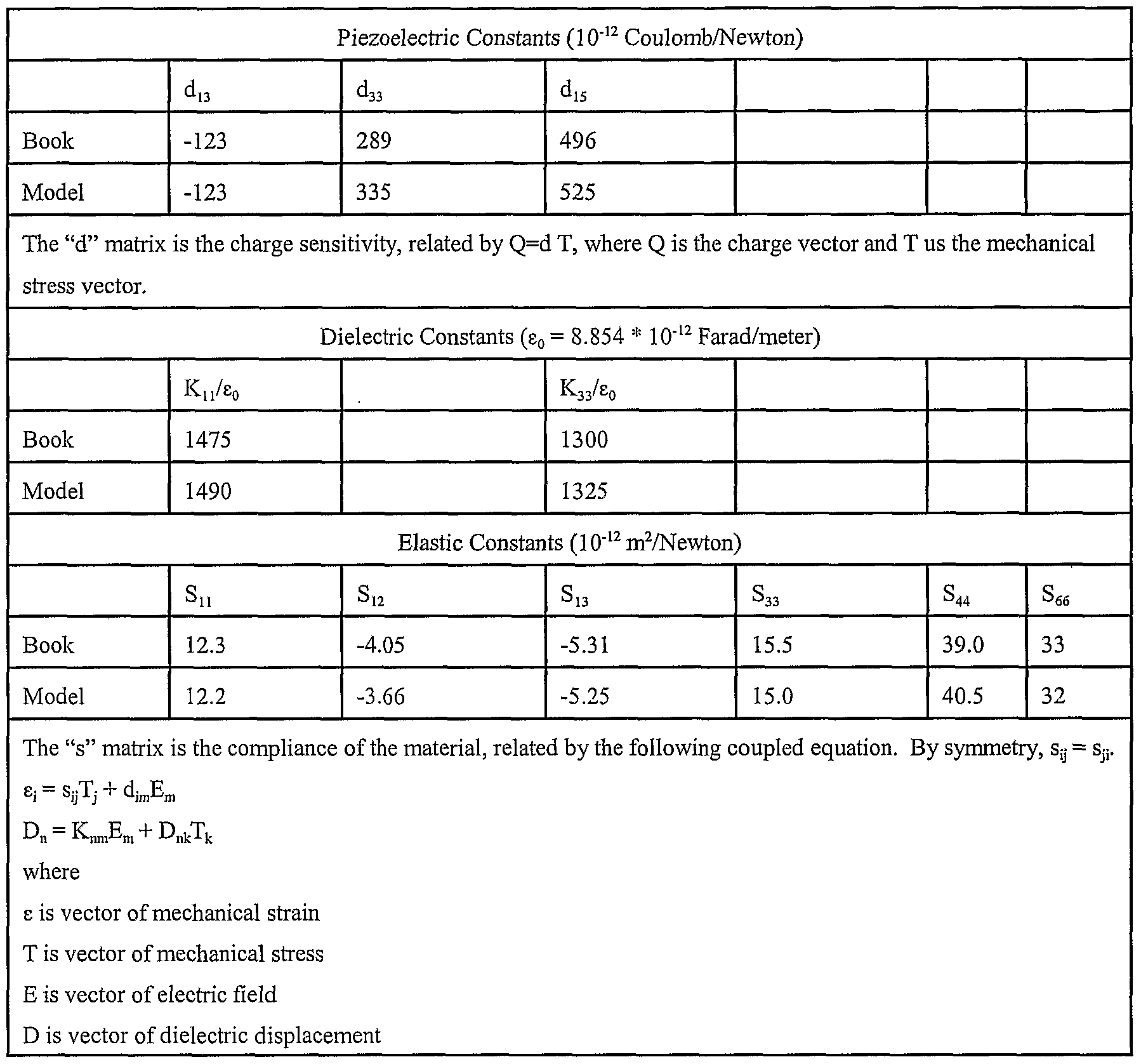
- Material properties of the piezoelectric material are provided as input parameters to the FEA model.
- the material properties of the piezoelectric element 102 for PZT4 are shown in Table 1, listing both "book” values commonly found in textbooks and "model” values.
- the model values have been refined for the material properties (of PZT, for example) by iteratively adjusting the values to obtain the best match between experiment and predictions of the FEA over a number of trials.
- the values, deduced in this way, are typically more precise than those provided by the manufacturer, mainly because the model values are measured at the operating (ultrasonic) frequency whereas the manufacturer's values are typically measured at low frequency (below 1 kHz).
- the resonance frequency and the acoustic sensitivity in both transmission and reception of ultrasonic acoustic waves) are considered.
- the ability of FEA modeling to predict transducer performance depends of the values of the material properties used at the outset of the FEA calculation - the more accurate the material values, the more accurate are the FEA predictions.
- the temperature expansion coefficient is listed in the second set of numbers, and the charge sensitivity [d], listed in the third set of numbers, relates the electrical charge produced in PZT4 to the stress applied to the material. (The subscript notation is standard to those skilled in the art.)
- the relative dielectric constant [k] is listed in the fourth set of numbers, and the elastic compliance [s], listed in the fifth set of numbers, primarily determines the mechanical resonance frequencies of the transducer 60.
- the two constitutive equations shown at the end of TABLE 1 couple the mechanical and piezoelectric variables.
- the aspect ratio of the piezoelectric element 102 is optimized for the specific material properties listed in TABLE 1. That is, the transducer designer chose dimensions and iterated these dimensions until a "high coupling" mode (FIG. 15A) was achieved, (hi FIGS. 14 and 15 A, only one quadrant is modeled as shown, since the other quadrants can be deduced on the basis of symmetry of element 102.) When “high coupling” occurs, most of the vibration is uniform so that a well-defined acoustic beam is formed. In comparison, “poor coupling” (FIG.
- the maximum acoustic signal occurred at about 235 kHz, for an element 62 having a length of about 1.25 inches, a height of about 0.23 inches and width of about 0.22 inches.
- the length, height, and width of the element 62 can vary between 1.0 to 1.3 inches in length, 0.1 to 0.5 inches in height, and 0.1 to 0.5 inches in width depending upon the desired frequency.
Landscapes
- Physics & Mathematics (AREA)
- Engineering & Computer Science (AREA)
- General Physics & Mathematics (AREA)
- Radar, Positioning & Navigation (AREA)
- Remote Sensing (AREA)
- Acoustics & Sound (AREA)
- Aviation & Aerospace Engineering (AREA)
- Multimedia (AREA)
- Computer Networks & Wireless Communication (AREA)
- Life Sciences & Earth Sciences (AREA)
- Hydrology & Water Resources (AREA)
- Transducers For Ultrasonic Waves (AREA)
- Testing Or Calibration Of Command Recording Devices (AREA)
- Measurement Of Velocity Or Position Using Acoustic Or Ultrasonic Waves (AREA)
Abstract
Description

Claims
Priority Applications (2)
| Application Number | Priority Date | Filing Date | Title |
|---|---|---|---|
| GB0502695A GB2407874B (en) | 2002-08-08 | 2003-08-05 | Combined speed and depth transducer for marine applications |
| AU2003261348A AU2003261348A1 (en) | 2002-08-08 | 2003-08-05 | Combined speed and depth transducer for marine applications |
Applications Claiming Priority (4)
| Application Number | Priority Date | Filing Date | Title |
|---|---|---|---|
| US40249302P | 2002-08-08 | 2002-08-08 | |
| US60/402,493 | 2002-08-08 | ||
| US42951402P | 2002-11-26 | 2002-11-26 | |
| US60/429,514 | 2002-11-26 |
Publications (2)
| Publication Number | Publication Date |
|---|---|
| WO2004015428A2 true WO2004015428A2 (en) | 2004-02-19 |
| WO2004015428A3 WO2004015428A3 (en) | 2004-06-10 |
Family
ID=31720603
Family Applications (1)
| Application Number | Title | Priority Date | Filing Date |
|---|---|---|---|
| PCT/US2003/024301 Ceased WO2004015428A2 (en) | 2002-08-08 | 2003-08-05 | Combined speed and depth transducer for marine applications |
Country Status (4)
| Country | Link |
|---|---|
| US (1) | US6904798B2 (en) |
| AU (1) | AU2003261348A1 (en) |
| GB (1) | GB2407874B (en) |
| WO (1) | WO2004015428A2 (en) |
Families Citing this family (23)
| Publication number | Priority date | Publication date | Assignee | Title |
|---|---|---|---|---|
| US7293479B2 (en) * | 2005-11-23 | 2007-11-13 | Honeywell International Inc. | Speed and temperature sensing in separate cavities in a single sensing head |
| US7961552B2 (en) * | 2008-08-28 | 2011-06-14 | Airmar Technology Corporation | Fan beam transducer assembly |
| US8300499B2 (en) | 2009-07-14 | 2012-10-30 | Navico, Inc. | Linear and circular downscan imaging sonar |
| US8305840B2 (en) | 2009-07-14 | 2012-11-06 | Navico, Inc. | Downscan imaging sonar |
| US9142206B2 (en) | 2011-07-14 | 2015-09-22 | Navico Holding As | System for interchangeable mounting options for a sonar transducer |
| US9182486B2 (en) | 2011-12-07 | 2015-11-10 | Navico Holding As | Sonar rendering systems and associated methods |
| US9268020B2 (en) | 2012-02-10 | 2016-02-23 | Navico Holding As | Sonar assembly for reduced interference |
| US9354312B2 (en) | 2012-07-06 | 2016-05-31 | Navico Holding As | Sonar system using frequency bursts |
| US9429588B2 (en) | 2012-08-16 | 2016-08-30 | Brickhouse Innovations, Llc | Electromagnetic boat speedometer having removable electrodes |
| US9513373B2 (en) | 2012-11-09 | 2016-12-06 | Airmar Technology Corporation | Speed sensor |
| US9594165B2 (en) | 2012-11-09 | 2017-03-14 | Airmar Technology Corporation | Speed sensor |
| US9910025B2 (en) * | 2015-06-23 | 2018-03-06 | Simmonds Precision Products, Inc. | Integrated active fuel characteristic sensor |
| US11278004B2 (en) | 2015-12-15 | 2022-03-22 | Battelle Memorial Institute | Transmitters for animals and methods for transmitting from animals |
| US10236920B2 (en) | 2015-12-15 | 2019-03-19 | Battelle Memorial Institute | Signal transmitter and methods for transmitting signals from animals |
| US10151829B2 (en) | 2016-02-23 | 2018-12-11 | Navico Holding As | Systems and associated methods for producing sonar image overlay |
| NL2016557B1 (en) * | 2016-04-06 | 2017-10-17 | Fugro Eng B V | Pressure measurement device. |
| US10531639B2 (en) | 2016-08-25 | 2020-01-14 | Battelle Memorial Institute | Systems and methods for monitoring organisms within an aquatic environment |
| US11367425B2 (en) * | 2017-09-21 | 2022-06-21 | Navico Holding As | Sonar transducer with multiple mounting options |
| US10852142B2 (en) * | 2017-11-14 | 2020-12-01 | Airmar Technology Corporation | Dual-axis electromagnetic speed sensor with depth |
| US11533818B2 (en) * | 2019-03-12 | 2022-12-20 | Battelle Memorial Institute | Sensor assemblies and methods for emulating interaction of entities within water systems |
| JP6976010B2 (en) * | 2019-11-28 | 2021-12-01 | 本多電子株式会社 | Ultrasonic wave transmitter / receiver |
| US11841427B2 (en) * | 2019-11-28 | 2023-12-12 | Honda Electronics Co., Ltd. | Ultrasonic-wave transmitter/receiver |
| MX2023007776A (en) | 2022-07-07 | 2024-01-08 | Neptune Tech Group Inc | Ultrasonic meter with single transducer. |
Family Cites Families (10)
| Publication number | Priority date | Publication date | Assignee | Title |
|---|---|---|---|---|
| US4455503A (en) * | 1982-06-17 | 1984-06-19 | Murata Manufacturing Co., Ltd. | Rectangular piezoelectric resonator with a slot in one surface |
| US4836020A (en) * | 1987-01-28 | 1989-06-06 | Airmar Technology Corporation | Marine instrument |
| US5182952A (en) * | 1991-01-17 | 1993-02-02 | Omega Engineering, Inc. | Paddlewheel flowmeter assembly |
| US5235557A (en) * | 1992-02-13 | 1993-08-10 | Karl Masreliez | Combined speed and depth sensor transducer |
| GB2277228B (en) | 1993-04-14 | 1996-12-04 | Murata Manfacturing Co Ltd | Vibrator,resonator and resonance component utilizing width expansion mode |
| US5838635A (en) * | 1994-11-14 | 1998-11-17 | Masreliez; Karl | Thin speed transducer sensor |
| US5581025A (en) * | 1996-02-12 | 1996-12-03 | Airmar Technology Corp. | Marine instrument |
| US5719824A (en) * | 1996-05-07 | 1998-02-17 | Airmar Technology Corp. | Transducer assembly with acoustic damping |
| SI20046A (en) | 1998-07-16 | 2000-02-29 | Iskraemeco, Merjenje In Upravljanje Energije, D.D. | Ultrasonic transducer and procedure for its manufacture |
| DE10009644A1 (en) | 2000-03-01 | 2001-09-06 | Siegfried R J Fahrentholz | Echo sounding sonar with digital data output for ships, has echo-sounding electronics which emit inhibiting signal beginning with transmitter trigger and ending slightly before the echo delay |
-
2003
- 2003-07-30 US US10/630,625 patent/US6904798B2/en not_active Expired - Lifetime
- 2003-08-05 AU AU2003261348A patent/AU2003261348A1/en not_active Abandoned
- 2003-08-05 WO PCT/US2003/024301 patent/WO2004015428A2/en not_active Ceased
- 2003-08-05 GB GB0502695A patent/GB2407874B/en not_active Expired - Lifetime
Also Published As
| Publication number | Publication date |
|---|---|
| WO2004015428A3 (en) | 2004-06-10 |
| GB2407874A (en) | 2005-05-11 |
| US6904798B2 (en) | 2005-06-14 |
| AU2003261348A8 (en) | 2004-02-25 |
| GB2407874B (en) | 2006-08-16 |
| AU2003261348A1 (en) | 2004-02-25 |
| GB0502695D0 (en) | 2005-03-16 |
| US20040074294A1 (en) | 2004-04-22 |
Similar Documents
| Publication | Publication Date | Title |
|---|---|---|
| US6904798B2 (en) | Multi-functional marine sensing instrument | |
| US9308554B2 (en) | Ultrasonic/acoustic transducer | |
| US4733379A (en) | Line array transducer assembly | |
| JP5709914B2 (en) | Sonar assembly with reduced interference | |
| JP3950755B2 (en) | Ultrasonic transducers that increase the resolution of imaging systems | |
| US20140092709A1 (en) | Pvdf sonar transducer system | |
| US9016129B2 (en) | Acoustic vector sensor having an accelerometer with in-band resonant frequency | |
| US11397263B2 (en) | Sonar system with acoustic beam reflector | |
| US4906886A (en) | Ultrasound sensor | |
| US20190257930A1 (en) | Multi frequency piston transducer | |
| EP1891461B1 (en) | Sonar imaging system for mounting to watercraft | |
| De Jong et al. | Vibration modes, matching layers and grating lobes | |
| EP2735380A1 (en) | A transducer for a locator beacon and an underwater locator beacon | |
| Hurmila et al. | Ultrasonic transducers using PVDF | |
| JP2000509649A (en) | Bending plate acoustic transducer with low resonance frequency | |
| US5367501A (en) | Dual-frequency sonar system | |
| US9035537B2 (en) | Cost effective broadband transducer assembly and method of use | |
| US6050361A (en) | Cavitation-resistant sonar array | |
| JP7663012B2 (en) | Ultrasonic Sensor | |
| US12601819B2 (en) | Sonar system including transducer elements with a gap therebetween | |
| US6690620B1 (en) | Sonar transducer with tuning plate and tuning fluid | |
| CN219785488U (en) | Ultrasonic transducer for underwater ranging | |
| EP1393821A1 (en) | Ultrasonic transducer | |
| JP2002044787A (en) | Broadband transducer | |
| Lancee et al. | Design and construction of an esophageal phased array probe |
Legal Events
| Date | Code | Title | Description |
|---|---|---|---|
| AK | Designated states |
Kind code of ref document: A2 Designated state(s): AE AG AL AM AT AU AZ BA BB BG BR BY BZ CA CH CN CO CR CU CZ DE DK DM DZ EC EE ES FI GB GD GE GH GM HR HU ID IL IN IS JP KE KG KP KR KZ LC LK LR LS LT LU LV MA MD MG MK MN MW MX MZ NI NO NZ OM PG PH PL PT RO RU SC SD SE SG SK SL SY TJ TM TN TR TT TZ UA UG US UZ VC VN YU ZA ZM ZW |
|
| AL | Designated countries for regional patents |
Kind code of ref document: A2 Designated state(s): GH GM KE LS MW MZ SD SL SZ TZ UG ZM ZW AM AZ BY KG KZ MD RU TJ TM AT BE BG CH CY CZ DE DK EE ES FI FR GB GR HU IE IT LU MC NL PT RO SE SI SK TR BF BJ CF CG CI CM GA GN GQ GW ML MR NE SN TD TG |
|
| 121 | Ep: the epo has been informed by wipo that ep was designated in this application | ||
| ENP | Entry into the national phase |
Ref document number: 0502695 Country of ref document: GB Kind code of ref document: A Free format text: PCT FILING DATE = 20030805 |
|
| WWE | Wipo information: entry into national phase |
Ref document number: 0502695.0 Country of ref document: GB |
|
| 122 | Ep: pct application non-entry in european phase | ||
| NENP | Non-entry into the national phase |
Ref country code: JP |
|
| WWW | Wipo information: withdrawn in national office |
Ref document number: JP |
|
| WWW | Wipo information: withdrawn in national office |
Ref document number: 0502695.0 Country of ref document: GB |