WO2005103584A1 - ヒートポンプ装置 - Google Patents
ヒートポンプ装置 Download PDFInfo
- Publication number
- WO2005103584A1 WO2005103584A1 PCT/JP2005/007898 JP2005007898W WO2005103584A1 WO 2005103584 A1 WO2005103584 A1 WO 2005103584A1 JP 2005007898 W JP2005007898 W JP 2005007898W WO 2005103584 A1 WO2005103584 A1 WO 2005103584A1
- Authority
- WO
- WIPO (PCT)
- Prior art keywords
- generator
- expander
- refrigerant
- current
- power
- Prior art date
- Legal status (The legal status is an assumption and is not a legal conclusion. Google has not performed a legal analysis and makes no representation as to the accuracy of the status listed.)
- Ceased
Links
Classifications
-
- F—MECHANICAL ENGINEERING; LIGHTING; HEATING; WEAPONS; BLASTING
- F25—REFRIGERATION OR COOLING; COMBINED HEATING AND REFRIGERATION SYSTEMS; HEAT PUMP SYSTEMS; MANUFACTURE OR STORAGE OF ICE; LIQUEFACTION SOLIDIFICATION OF GASES
- F25B—REFRIGERATION MACHINES, PLANTS OR SYSTEMS; COMBINED HEATING AND REFRIGERATION SYSTEMS; HEAT PUMP SYSTEMS
- F25B9/00—Compression machines, plants or systems, in which the refrigerant is air or other gas of low boiling point
- F25B9/06—Compression machines, plants or systems, in which the refrigerant is air or other gas of low boiling point using expanders
-
- F—MECHANICAL ENGINEERING; LIGHTING; HEATING; WEAPONS; BLASTING
- F01—MACHINES OR ENGINES IN GENERAL; ENGINE PLANTS IN GENERAL; STEAM ENGINES
- F01D—NON-POSITIVE DISPLACEMENT MACHINES OR ENGINES, e.g. STEAM TURBINES
- F01D15/00—Adaptations of machines or engines for special use; Combinations of engines with devices driven thereby
- F01D15/10—Adaptations for driving, or combinations with, electric generators
-
- F—MECHANICAL ENGINEERING; LIGHTING; HEATING; WEAPONS; BLASTING
- F25—REFRIGERATION OR COOLING; COMBINED HEATING AND REFRIGERATION SYSTEMS; HEAT PUMP SYSTEMS; MANUFACTURE OR STORAGE OF ICE; LIQUEFACTION SOLIDIFICATION OF GASES
- F25B—REFRIGERATION MACHINES, PLANTS OR SYSTEMS; COMBINED HEATING AND REFRIGERATION SYSTEMS; HEAT PUMP SYSTEMS
- F25B9/00—Compression machines, plants or systems, in which the refrigerant is air or other gas of low boiling point
- F25B9/002—Compression machines, plants or systems, in which the refrigerant is air or other gas of low boiling point characterised by the refrigerant
- F25B9/008—Compression machines, plants or systems, in which the refrigerant is air or other gas of low boiling point characterised by the refrigerant the refrigerant being carbon dioxide
-
- F—MECHANICAL ENGINEERING; LIGHTING; HEATING; WEAPONS; BLASTING
- F25—REFRIGERATION OR COOLING; COMBINED HEATING AND REFRIGERATION SYSTEMS; HEAT PUMP SYSTEMS; MANUFACTURE OR STORAGE OF ICE; LIQUEFACTION SOLIDIFICATION OF GASES
- F25B—REFRIGERATION MACHINES, PLANTS OR SYSTEMS; COMBINED HEATING AND REFRIGERATION SYSTEMS; HEAT PUMP SYSTEMS
- F25B1/00—Compression machines, plants or systems with non-reversible cycle
- F25B1/04—Compression machines, plants or systems with non-reversible cycle with compressor of rotary type
-
- F—MECHANICAL ENGINEERING; LIGHTING; HEATING; WEAPONS; BLASTING
- F25—REFRIGERATION OR COOLING; COMBINED HEATING AND REFRIGERATION SYSTEMS; HEAT PUMP SYSTEMS; MANUFACTURE OR STORAGE OF ICE; LIQUEFACTION SOLIDIFICATION OF GASES
- F25B—REFRIGERATION MACHINES, PLANTS OR SYSTEMS; COMBINED HEATING AND REFRIGERATION SYSTEMS; HEAT PUMP SYSTEMS
- F25B2309/00—Gas cycle refrigeration machines
- F25B2309/06—Compression machines, plants or systems characterised by the refrigerant being carbon dioxide
- F25B2309/061—Compression machines, plants or systems characterised by the refrigerant being carbon dioxide with cycle highest pressure above the supercritical pressure
-
- F—MECHANICAL ENGINEERING; LIGHTING; HEATING; WEAPONS; BLASTING
- F25—REFRIGERATION OR COOLING; COMBINED HEATING AND REFRIGERATION SYSTEMS; HEAT PUMP SYSTEMS; MANUFACTURE OR STORAGE OF ICE; LIQUEFACTION SOLIDIFICATION OF GASES
- F25B—REFRIGERATION MACHINES, PLANTS OR SYSTEMS; COMBINED HEATING AND REFRIGERATION SYSTEMS; HEAT PUMP SYSTEMS
- F25B2600/00—Control issues
- F25B2600/17—Control issues by controlling the pressure of the condenser
Definitions
- the present invention relates to a heat pump device that recovers power by connecting a generator to an expander.
- FIG. 10 As a conventional general vapor compression refrigeration apparatus, there is one having a configuration shown in Fig. 10. 10 includes a compressor 101, a radiator 102, an expansion valve 103, and an evaporator 104. These elements are connected by piping, and the refrigerant circulates as shown by the outlined arrows in the figure.
- the operating principle of the vapor compression refrigeration system is as follows.
- the pressure and temperature of the refrigerant are increased by the compressor 101, which then enters the radiator 102 and is cooled. Thereafter, the refrigerant in the high pressure state is reduced to the evaporation pressure by the expansion valve 103, and absorbs heat in the evaporator 104 to be vaporized. Then, the refrigerant that has exited the evaporator 104 returns to the compressor 101.
- This device has a very low global warming potential without destroying the ozone layer as a refrigerant! And carbon dioxide.
- a vapor compression refrigeration system using carbon dioxide as a refrigerant has lower energy efficiency coefficient of performance (COP) than a refrigeration system using chlorofluorocarbon as a refrigerant.
- COP energy efficiency coefficient of performance
- more electric power is required than a refrigeration system using chlorofluorocarbon as a refrigerant. Therefore, many fossil fuels are required as energy, and the refrigerant itself has a global warming potential, and at the very least, a large amount of carbon dioxide is emitted. Therefore, it is necessary to improve the COP of a vapor compression refrigeration system using carbon dioxide as a refrigerant, and various configurations and methods have already been proposed.
- the compressor 201 is driven by the motor 205, the refrigerant compressed by the compressor 201 is cooled by the radiator 202, and then the expander is provided with the expansion ratio control means 203. Go through 204.
- the expander 204 assists in driving the compressor 201 via the main shaft 213.
- the refrigerant expands in the expander 204 and vaporizes by absorbing heat from the outside in the evaporator 206. After that, the flow returns to the compressor 201 again.
- a circuit constituted by the compressor 201, the radiator 202, the expander 204, and the evaporator 206 is connected by a pipe 207. Note that an oil separator 208 and an accumulator 209 may be provided in order to improve performance and reliability.
- the expansion ratio control means 203 is controlled by the calculation means 210.
- a temperature sensor 211 and a pressure sensor 212 are attached to detect the state of the refrigerant at the outlet side of the radiator 202.
- the expansion device 204 is used to assist the driving of the compressor 201 by the force of the expansion of the refrigerant, the total amount of energy used is reduced and the COP is improved. Is possible.
- FIG. 12 As shown in FIG. 12, as shown in a pressure-enthalpy diagram showing a state of a refrigerant in a refrigeration cycle using dioxide carbon as a refrigerant, that is, a so-called Mollier diagram, when a conventional expansion valve is used as expansion means.
- a pressure-enthalpy diagram showing a state of a refrigerant in a refrigeration cycle using dioxide carbon as a refrigerant
- Mollier diagram when a conventional expansion valve is used as expansion means.
- isenthalpy expansion is performed, but isentropic expansion is performed by an expander (indicated by a dotted line in the figure), and the overall efficiency can be improved by using the power recovered by the expander.
- the compressed refrigerant is cooled by the radiator 402 by the compressor 401 driven by the prime mover 405, and then passes through the expander 403 when passing through the expander 403.
- the connected generator 404 generates power (Patent Document 1, Patent Document 2). Then, the refrigerant expands in the expander 403, absorbs heat from the outside in the evaporator 406, evaporates, and returns to the compressor 401 again.
- This device generates electric power by rotating the generator 404 with the force of the expansion of the refrigerant, and by using that electric power, the total amount of energy used is reduced, thereby improving the COP. is there.
- Patent Document 4 an exciter is used as such a generator 404 (Patent Document 4).
- 14 and 15 show the refrigeration apparatus disclosed in Patent Document 4.
- this refrigerating apparatus has a configuration in which refrigerant is circulated in the order of a compressor 501, a condenser 502, a liquid receiver 503, an expander 504, and an evaporator 505.
- a generator 506 coaxially connected to the drive shaft, a superheat degree detector 512 provided at the outlet of the evaporator 505 for detecting the degree of superheat of the refrigerant, and a generator 506 based on the signal.
- the control unit 511 includes a control unit 511, a rectifier 508 for converting AC generated by the generator 506 to DC, and a capacitor 510 for recovering DC power.
- the generator 506 is controlled by adjusting the exciting current of the generator 506 (that is, the current flowing through the exciting coil), and the expansion torque is increased or decreased by increasing or decreasing the load torque of the generator 506.
- the rotation of the 504 is controlled to adjust the flow rate of the refrigerant, and the electric power generated by the generator 506 is efficiently collected in the battery 510.
- the generator 506 is configured to input a driving force by a driving shaft fixed to the other end of the rotor and generate power.
- the generator 506 is provided with a brush, and the brush has a function of sliding in a slip ring to supply an exciting current to the rotor coil.
- the drive shaft is rotated by the expansion rotation of the refrigerant, a magnetic field is generated by the exciting current supplied to the rotor coil, and an electromotive force is generated in the stator coil.
- the electromotive force is output from the stator coil as AC power.
- the excitation unit 507 for generating the excitation current of the generator 506 has the circuit configuration shown in FIG. 15, and uses the excitation current control signal output from the control unit 511 as an input signal, and outputs the excitation current from the excitation unit 507. Is supplied to the generator 506 as an output signal. That is, the excitation current control signal output from the control unit 511 is applied to the base of the npn-type transistor Tr604 (hereinafter, Tr604).
- Tr604 npn-type transistor
- the emitter of the Tr 604 is connected to the minus terminal of the generator 506, and the collector of the Tr 604 is connected to the inlet coil 602 of the generator 506 via the resistor 605.
- Tr603 The base of the transistor Tr603 (hereinafter, Tr603) is connected to the collector of Tr604, the emitter of Tr603 is connected to the minus terminal of the generator 506, and the collector of Tr603 is connected to the plus terminal of the generator 506 via the rotor coil 602. It is connected to the.
- Tr603 when the exciting current control signal applied to the base of the Tr 604 from the control unit 511 increases, the Tr 604 conducts to increase the exciting current flowing through the rotor coil 602, and conversely, the exciting current applied to the base of the Tr 604 When the control signal is decreased, the excitation current is reduced!
- control unit 511 that outputs the excitation current control signal is configured to control the excitation current control signal output to the excitation unit 507 so that the refrigerant flow rate becomes appropriate based on the refrigeration cycle temperature information and the like. ing. For example, when the refrigerant circulation amount is small, the generator 50 6, the exciting current is reduced, the load torque is reduced, and the rotation speed of the expander 504 is increased. Conversely, when the circulation amount is large, the exciting current of the generator 506 is increased, the load torque is increased, and the rotation speed of the expander 504 is reduced. Further, the AC voltage generated by the generator 506 is converted to a DC voltage via the rectifier 508, and is controlled via the variable load resistor 509 so that the charging voltage becomes substantially constant, thereby charging the battery 510.
- the number of rotations of the expander 504 was controlled by controlling the exciting current by the generator 506 including the rotor coil 602 and the exciting unit 507 for supplying the exciting current to the rotor coil 602. .
- Patent Document 5 discloses that a variable speed inverter is controlled in a wind power generator that converts the output of a permanent magnet type synchronous generator shaft-coupled to a wind turbine using an AC-DC converter (variable speed inverter). This describes that variable speed control of the output voltage of the generator and its rotation speed is performed.
- Patent Document 6 describes that the torque of the generator is controlled after estimating the magnetic pole position using an output current and a terminal voltage force position estimator of the permanent magnet type synchronous generator.
- Patent document 1 Japanese Patent Application Laid-Open No. 2000-241033
- Patent Document 2 Japanese Patent Application Laid-Open No. 2000-249411
- Patent Document 3 JP 2001-165513 A
- Patent Document 4 JP-A-1-168518
- Patent Document 5 JP-A-2000-345952
- Patent Document 6 JP-A-2002-354896
- the expansion device cannot be forcibly rotated at the time of start-up or the like, thereby reducing the reliability of the refrigeration cycle.
- the present invention solves the above-mentioned problems, and the weight on the rotor side is reduced, and the rotor is provided with an exciting portion and a coil, so that no electricity flows therethrough and power loss in the rotor is lost.
- Another object of the present invention is to provide a heat pump device that can increase the power generation efficiency due to the absence of the heat pump, further simplify the configuration on the rotor side and reduce the cost, and can utilize the effectiveness of the generator. I do.
- Another object is to provide a highly efficient and highly reliable heat pump device.
- it is possible to control the expander over a wide range of rotational speeds, optimize efficiency, control a permanent magnet type synchronous generator without a rotational position sensor, and improve the point force such as sealing.
- the starting performance is improved to improve the reliability of the refrigeration cycle.
- the heat pump device includes a compressor that compresses a refrigerant, a radiator that cools the refrigerant compressed by the compressor, an expander that expands the refrigerant that has passed through the radiator, and an expander that expands the expander.
- the evaporator that evaporates the compressed refrigerant, the refrigerant pipe that circulates the refrigerant through the compressor, the radiator, the expander, and the evaporator, and is installed between the compressor and the expander to detect the pressure of the refrigerant.
- the current sensor to be detected and the AC power output from the permanent magnet type synchronous generator are converted into DC power, and the magnetic pole position of the permanent magnet type synchronous generator is estimated based on the current value detected by the current sensor.
- the magnetic pole position Since it has a first converter for controlling the rotation speed of the permanent magnet type synchronous generator to a predetermined value, and a generator rotation speed control means for controlling the first converter based on signals of a pressure sensor and a temperature sensor force. is there.
- the rotation speed of the permanent magnet synchronous generator is controlled to a predetermined value by the first converter, and power can be recovered by the permanent magnet synchronous generator connected to the expander. Since the permanent magnet type synchronous generator does not have an excitation section and the like, the weight of the generator is reduced, and the power generation efficiency is increased, thereby realizing a heat pump device with high overall efficiency and low cost. Further, the cycle efficiency of the heat pump device can be optimized.
- the heat pump device is the heat pump device according to the first invention, wherein the magnetic pole position and the rotation speed of the permanent magnet type synchronous generator are estimated based on the current value detected by the current sensor, and the current value The current value and the rotation speed of the permanent magnet type synchronous generator are controlled to predetermined values using the magnetic pole position and the rotation speed.
- the rotation speed of the permanent magnet type synchronous generator can be controlled without using the rotation position sensor, so that the generator and the expander can be integrally housed in the same shell. It is also possible to realize a heat pump device having excellent sealing properties and high reliability.
- the heat pump device according to a third aspect of the present invention is the heat pump device according to the first aspect, wherein the second converter that converts alternating current of commercial power into direct current, and the first and second converters And an inverter that connects the DC output from the inverter to the input terminal of the inverter, converts the DC into AC of a predetermined frequency, and drives the compressor.
- the third aspect it is possible to use the power generated by the expander as the drive power for the compressor, to achieve a simple configuration, and to efficiently recover the power.
- the heat pump device is the heat pump device according to the first invention, wherein the pressure sensor and the temperature sensor are provided between the compressor and the expander to detect the pressure and temperature of the refrigerant; And a generator current control means for controlling the current value of the generator so that the pressure of the refrigerant is adjusted to the optimum pressure by the signal of the temperature sensor force.
- the cycle efficiency of the heat pump device can be optimized.
- the heat pump device is the heat pump device according to the first invention, wherein the pressure sensor and the temperature sensor are provided between the compressor and the expander to detect the pressure and temperature of the refrigerant; And generator power generation amount control means for controlling the power generation amount of the generator so that the pressure of the refrigerant is adjusted to the optimum pressure by the signal of the temperature sensor force.
- the cycle efficiency of the heat pump device can be optimized.
- a heat pump device is the heat pump device according to the first invention, wherein the generator is driven by the first converter when the expander is started.
- the expansion device can be started smoothly at the start of the system operation, and the reliability of the system can be improved.
- the heat pump device is the heat pump device according to the first aspect, wherein the operation of the generator by the first converter is started a predetermined time after the start of the compressor. It is.
- the system can be started up quickly.
- the heat pump device according to the eighth invention is the heat pump device according to the first invention.
- the refrigerant is carbon dioxide.
- a power recovery device is an expander that expands a working fluid, a permanent magnet synchronous generator connected to the expander, and a current sensor that detects a current flowing through the permanent magnet synchronous generator.
- the AC power output from the permanent magnet synchronous generator is converted to DC power, the magnetic pole position of the permanent magnet synchronous generator is estimated from the current value detected by the current sensor, and the current value and the magnetic pole position are used.
- a first converter for controlling the rotation speed of the permanent magnet type synchronous generator to a predetermined value.
- the rotation speed of the permanent magnet type synchronous generator is controlled to the predetermined value by the first converter, and power can be recovered by the permanent magnet type synchronous generator connected to the expander. Since the permanent magnet type synchronous generator does not have an excitation section or the like, the weight of the generator is reduced, and the power generation efficiency is increased, thereby realizing a heat pump device with high overall efficiency and low cost.
- the heat pump device of the present invention it is possible to reduce the weight of the generator on the rotor side without providing the excitation unit in the generator. Further, according to the device, power generation efficiency is increased because there is no power loss in the rotor, and a power recovery system with a simple configuration on the rotor side and low cost can be realized.
- the switching control of the generator by the first converter makes it possible to control the expander over a wide range through the generator, thereby improving power recovery efficiency and refrigeration system efficiency.
- FIG. 1 is a block diagram showing a heat pump device according to a first embodiment of the present invention.
- FIG. 2 is a detailed block diagram of a first converter of the heat pump device shown in FIG. 1.
- FIG. 3 is a block diagram showing a heat pump device according to a second embodiment of the present invention.
- FIG. 4 is a diagram showing an example of the efficiency of a refrigeration cycle with respect to a radiator outlet pressure and temperature.
- FIG. 5 is a flowchart for determining the number of revolutions of the expander in the heat pump device shown in FIG. 3
- FIG. 6 is a state transition diagram of the heat pump device shown in FIG. 3 when the expander is started.
- FIG. 6 is a state transition diagram of the heat pump device shown in FIG. 3 when the expander is started.
- FIG. 6 A block diagram showing a heat pump device according to a third embodiment of the present invention.
- FIG. 8 is a detailed block diagram of a first converter of the heat pump device shown in FIG. 7.
- FIG. 9 Flow chart of generator current determination in the heat pump device shown in FIG. 7
- FIG. 10 Configuration diagram showing a conventional vapor compression refrigeration device
- FIG. 11 is a configuration diagram showing a conventional refrigeration apparatus.
- FIG. 13 is a configuration diagram showing another conventional refrigeration apparatus.
- FIG. 14 is a configuration diagram showing a conventional refrigeration system
- FIG. 15 is a circuit diagram showing an excitation unit of a conventional refrigeration system.
- FIG. 1 is a block diagram showing a heat pump device according to a first embodiment of the present invention.
- the heat pump device according to the present embodiment includes an expander 711 that expands a working fluid, a permanent magnet synchronous generator 710 (hereinafter, a generator 710) connected to the expander 711, and an AC power output from the generator 710. And a first converter 708 having a function of converting the DC power into DC power and controlling the driving of the generator 710.
- a compressor 707 a motor 706 for driving the compressor 707, a motor driving device 704 for controlling the motor 706, a DC power converted from an AC power supply 701 by a rectifier circuit 702 and a smoothing capacitor 703, and a first And a power supply circuit for supplying the DC power from the converter 708 to the electric motor 706 via the motor driving device 704.
- a DC voltage obtained by rectifying an input from an AC power supply 701 of a commercial power supply into DC by a rectifier circuit 702 is subjected to a voltage smoothing by a smoothing capacitor 703 and then to a motor driving device.
- the voltage is converted into a three-phase AC voltage by the unit 704, and the electric motor 706 is thereby driven.
- the compressor 707 performs a compression function by driving the motor 706.
- the motor driving device 704 includes a switching element group 705 for converting a DC voltage to an AC and the like, and realizes a predetermined AC frequency of the switching element group 705 by a PWM (Pulse Width Modulation) method. By turning ON and OFF in this way, an arbitrary AC can be output.
- PWM Pulse Width Modulation
- the configuration of the rectifier circuit 702 and the smoothing capacitor 703 is a second converter, and the configuration of the motor driving device 704 is equivalent to an inverter.
- a first converter 708 for converting three-phase AC power generated by the generator 710 into DC is connected to the generator 710 installed for recovering power by the expander 711. .
- the first converter 708 converts AC power generated by the generator 710 into DC, and switches a switching element group 709 formed therein by a PWM method to provide a given target rotation speed. It has a function to rotate the generator 710.
- the function of controlling the number of revolutions of the generator 710 allows the number of revolutions of the expander 711 to be controlled via the generator 710, so that the heat pump device using the Can be driven at an optimum rotation speed. That is, the switching control of the first converter 708 enables a wide range of rotation control of the generator 710, that is, of the expander 711.
- a DC output line from the first converter 708 is connected in parallel to a DC power line obtained from the rectifier circuit 702 via the smoothing capacitor 703. As a result, the power regenerated from the first converter 708 is consumed for driving energy of the motor driving device 704.
- the power consumption Wm of the compressor 707 is usually larger than the regenerative power by the expander 711.
- Input power from AC power supply 701 in is a positive value.
- the regenerative current does not flow to the AC power supply 701, so that there is no need for a special system cooperation control device.
- the voltage of the smoothing capacitor 703 does not rise excessively. Therefore, with the heat pump device of the present embodiment having such a simple configuration, the power obtained by the generator 710 can be efficiently collected.
- FIG. 2 is a detailed block configuration diagram of a first converter of the heat pump device shown in FIG.
- two current sensors 805a, 805b, switching elements 803a, 803b, 803c, 803d, 803e, 803f and free-wheeling diodes 804a, 804b, 804c, 804d, 804e, 804f are paired.
- the power output of the three-phase alternating current of the generator 710 is connected via the first converter 708 to, for example, the DC power supply 801 and the smoothing capacitor 802 side.
- the DC power supply 801 and the smoothing capacitor 802 correspond to the rectifier circuit 702 and the smoothing capacitor 703 in FIG.
- the three-phase AC output is converted to DC by the first converter 708. At that time, control is performed such that the rotation speed of the generator 710 becomes the target rotation speed based on information on the target rotation speed given from outside.
- the switching pattern of the switching elements 803a to 803f of the first converter 708 is converted into the information of the magnetic pole position of the generator 710 from which the current information power of the generator 710 from which the power of the current sensors 805a and 805b is obtained is also estimated. It is determined from the information on the rotation speed of 710 and the information on the target rotation speed given from the outside. Further, this switching pattern signal is converted by a base dryer 808 into drive signals for electrically driving the switching elements 803a to 803f, and the switching elements 803a to 803f operate according to these drive signals. Become! / Next, the operation of first converter 708 will be described.
- Gpco and Gico are the speed control proportional gain and integral gain
- ⁇ is the rotation speed
- ⁇ * is the target rotation speed
- I * is the current command
- the current command creating means 811 calculates a d-axis current command Id * and a q-axis current command Iq * for realizing the current phase angle by the following formula.
- ⁇ is the current phase angle
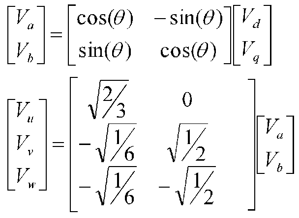
- phase currents Iu and Iv of the generator 710 detected by the current sensors 805a and 805b are calculated by the two-axis current conversion means 806 using the following equation (Equation 5). It is converted to a biaxial current of Iq and a d-axis current Id orthogonal to it.
- 0 is the rotor position (magnetic pole position of the generator).
- the current control means 810 performs a control operation using the given current commands Id * and Iq * and the current values Id and Iq so as to realize the current command by the following equation, and outputs the output voltage Vd , Vq.
- Vd GpdX (Id * -Id) + GidX ⁇ (Id * —Id)
- Vq GpqX (Iq * —Iq) + Giq X ⁇ (Iq * — Iq)... (Equation 7)
- Vd and Vq are d-axis voltage and q-axis voltage
- Gpd and Gid are d-axis current control proportional gain and integral gain
- Gpq and Giq are q-axis current control proportional gain and integral gain.
- Vu, Vv, and Vw are U-phase, V-phase, and W-phase voltages, and ⁇ is a rotor position.
- the sine wave voltage output means 809 generates a drive signal for driving the generator 710 based on information on the output voltages Vd, Vq and the rotor position estimated by the rotor position / rotation speed estimation means 807. Is output to the 808. Then, base driver 808 outputs a signal for driving switching elements 803a to 803f according to the drive signal. Thus, the generator 710 is driven at the target rotation speed (speed).
- phase currents (iu, iv, iw) flowing through the windings of each phase are obtained from the currents detected by the current sensors 805a and 805b. Also, based on the three-phase duty values Du, Dv, and Dw output by the sine wave voltage output means 809 and the power supply voltage Vdc obtained from the voltage dividing resistors 813a and 813b, the phase voltages applied to the windings of the respective phases are obtained. (vu, w, vw) is obtained by the following equation.
- ew vw— R'iw— L 'd (iw) / dt #
- R resistance
- L inductance
- d (iu) Zdt, d (iv) / dt, and d (iw) Zdt are time derivatives of, iv, and iw, respectively.
- the rotor position ⁇ and the estimated rotational speed ⁇ m are estimated using the calculated induced voltage values eu, ev, and ew.
- This is a method of estimating the rotor position ⁇ by correcting the estimated angle ⁇ m recognized by the motor driving device using an error in the induced voltage so as to converge to a true value.
- the estimated rotational speed com is also estimated from the estimated angle ⁇ m.
- an induced voltage reference value (eum, evm, ewm) of each phase is obtained by the following equation.
- the em induced voltage amplitude value em is obtained by matching the amplitude values of the induced voltage values eu, ev, and ew.
- Equation 16 the induced voltage reference value es m of each phase is subtracted from the induced voltage value es of each phase to obtain the deviation ⁇ .
- the estimated angle ⁇ m becomes a true value, so that the deviation ⁇ is made to converge to 0, for example, by converging the deviation ⁇ by ⁇ operation, the estimated angle ⁇ m
- the true value is obtained as the estimated rotor position ⁇ (estimated magnetic pole position). Further, by calculating the fluctuation value of the estimated angle ⁇ m, the estimated rotational speed com can be estimated. It should be noted that this estimation method is obvious to those skilled in the art, and the description thereof will be omitted.
- the magnetic pole position and the rotation speed of the generator are estimated using the first converter power, for example, the current sensor and the rotor position rotation speed estimation means. Based on these estimated magnetic pole positions and estimated rotation speeds, the rotation speed of the permanent magnet type synchronous generator without the excitation section, etc., that is, the rotation speed of the expander, is controlled, and power is recovered by the generator connected to the expander. It can be performed efficiently. As a result, since there is no exciting part or coil on the rotor side of the generator, the weight of the generator is reduced, and power generation efficiency is increased because there is no power loss due to the exciting part. Simple configuration and low cost It is possible to provide a heat pump device that reduces the heat.
- the magnetic pole position of the generator can be known without a position sensor, for example, a shaft seal for an encoder is not required, and the expander and the generator can be housed in a sealed integral shell.
- the heat pump device can be realized with high reliability (sealability).
- FIG. 3 is a block diagram showing a heat pump device according to a second embodiment of the present invention.
- the heat pump device includes a compressor 901 that compresses a refrigerant, a radiator 902 that cools the refrigerant compressed by the compressor 901, and an expander 903 that expands the refrigerant that has passed through the radiator 902.
- a permanent magnet type synchronous generator 907 (hereinafter, referred to as a permanent magnet type generator 907) comprising an evaporator 904 for evaporating the refrigerant expanded by the expander 903, and a refrigerant pipe 914 for circulating the refrigerant between the above-described respective components.
- a generator 907), and a first converter 908 having a function of converting the AC power output from the generator 907 into DC power and controlling the driving of the generator 907.
- a motor 905 for driving the compressor 901 a motor driving device 906 for controlling the motor 905, a DC power converted from the AC power supply 911 by the rectifier circuit 912 and the smoothing capacitor 913, and a DC power from the first converter 908.
- the temperature sensor 916 and the like are configured to include a control circuit that outputs a signal to the first converter 908.
- pressure sensor 915 and the temperature sensor 916 are installed between the compressor 901 and the expander 903 on the high pressure side of the heat pump cycle. Is installed at the exit.
- first converter 908 connected to generator 907 has the same configuration as first converter 708 of the first embodiment, and a description thereof will be omitted. Next, the operation of the above configuration will be described.
- a compressed refrigerant is cooled by a radiator 902 by a compressor 901 driven by a motor driving device 906 and an electric motor 905, and then expanded when passing through an expander 903.
- the generator 907 connected to is rotated.
- the refrigerant expanded in the expander 903 absorbs heat from the outside in the evaporator 904 to vaporize, and then returns to the compressor 901 again.
- This closed circuit is connected by a refrigerant pipe 914.
- the DC voltage obtained by rectifying the input from the AC power supply 911 to DC by the rectifier circuit 912 is smoothed by a smoothing capacitor 913, and then converted into a three-phase AC voltage by a motor driving device 906. 905 is driven.
- the compressor 901 performs a compression function.
- the torque of the expander 903 generated by the expansion force of the refrigerant becomes the rotational force of the generator 907, and power is generated.
- the power generated by the generator 907 is converted to DC by the first converter 908, and then supplied to both ends of the smoothing capacitor 913.
- the electric power generated by the generator 907 connected to the expander 903 is used as auxiliary power for driving the motor of the compressor 901.
- the number of revolutions of generator 907 that is, expander 903, is controlled by first converter 908. Further, the number of rotations of the compressor 901 is controlled by the motor driving device 906.
- the first converter 908 is supplied with the target rotation speed from the expander rotation speed determination means 909.
- the expander rotational speed determining means 909 determines an optimal expander rotational speed (target rotational speed) based on the outlet temperature and the outlet pressure of the radiator 902 detected by the pressure sensor 915 and the temperature sensor 916. This optimum expander rotation speed is determined from the data of the efficiency of the refrigeration cycle with respect to the radiator outlet pressure and radiator outlet temperature shown in Fig. 4.
- the point that the efficiency of the present refrigeration cycle becomes maximum depending on the outlet pressure and the outlet temperature of the radiator 902, and the line connecting the points is the optimum efficiency pressure line in the figure.
- the optimal pressure is determined as the radiator outlet pressure at that time.
- FIG. 5 is a flowchart of the expansion machine rotation speed determination in the heat pump device shown in FIG. 3, and illustrates a procedure for determining the value of the expansion machine rotation speed that maximizes the cycle efficiency in the expansion machine rotation speed determining means 909. Show.
- step 101 the measured pressure and temperature values at the radiator outlet are input. Then, according to the optimum pressure data shown in FIG. 4, the optimum pressure value that maximizes the efficiency is calculated (step 102).
- step 103 it is determined in step 103 whether the measured current outlet pressure is larger than the optimum pressure. If the outlet pressure is higher than the optimum pressure, the target rotation speed of the expander 903 is increased so as to reduce the outlet pressure (step 104). For example, an initial rotational speed command nl described later is used as an initial value, and a calculation for increasing the initial rotational speed command nl is performed and replaced with a target rotational speed for the next control. Then, the target rotation speed for lowering the outlet pressure is output to first converter 908 (step 105). As a result, the pressure difference between the inlet and the outlet of the expander 903 is reduced, and as a result, the pressure on the high pressure side in the refrigeration cycle decreases.
- the target rotation speed of the expander 903 is reduced so as to increase the outlet pressure (step 106). Then, the target rotation speed of the outlet pressure increase is output to first converter 908 (step 107). As a result, the pressure difference between the inlet and the outlet of the expander 903 increases, and as a result, the pressure on the high pressure side in the refrigeration cycle increases.
- the outlet pressure of the radiator 902 becomes a predetermined optimum pressure value that maximizes the efficiency of the refrigeration cycle.
- Step 102 corresponds to an optimum value calculating means for calculating an optimum pressure from data of a radiator outlet pressure, a radiator outlet temperature, an optimum pressure, and the like.
- first converter 908 sets the pressure of the refrigerant to a predetermined optimal pressure value based on the target rotation speed from expander rotation speed determination means 909.
- the cycle efficiency of the heat pump device can be optimized by controlling the rotation speed of the generator 907 (that is, the rotation speed of the expander 903).
- cycle efficiency is optimized by the present embodiment, and the coefficient of performance (COP) is improved, so that it is possible to use carbon dioxide as a refrigerant in the heat pump device, which helps prevent global warming. be able to.
- COP coefficient of performance
- FIG. 7 is a state transition diagram at the time of starting the expander in the pump device, and shows a setting sequence of the number of revolutions at the time of starting in the expander starting means 910. That is, it shows an example of transition of the radiator outlet pressure, the expander rotation speed, and the generator current from the start to the steady state.
- the expander 903 rotates smoothly during that time. As a result, the original expansion function is exhibited, and the start-up of the heat pump system is quickly performed.
- the initial rotational speed command (initial value of the target rotational speed) of the expander 903 is set to nl.
- the current of the generator 907 in the expander 903 is on the current side, that is, the power supply circuit power is also in the direction of the generator 907 (input power to the generator). Is controlled by the first converter 908 so as to flow in the negative current direction.
- the first converter 908 since the first converter 908 has a function to drive the generator 907 in a row, the expander using the generator as a motor is forcibly rotated at the time of start-up, and the start-up of the expander 903 is smoothly performed. This is to improve the refrigeration cycle reliability.
- the current of the generator 907 is on the regenerative side, that is, in the direction from the generator 907 to the power supply circuit (positive current direction for outputting electricity from the generator). It is controlled by the first converter 908 so that it flows. As a result, driving of the generator 907 in the regeneration mode is realized, and power recovery by the generator 907 is started.
- the expander rotational speed determining means 909 outputs a regular target rotational speed, and control is performed to set the outlet pressure to the optimum pressure value. That is, a steady operation is performed, and the radiator outlet pressure, the expander rotation speed, and the generator The current gradually increases to reach the optimum pressure value, the target rotation speed, and the target current.
- the system can be quickly started up and the expander 903 can be smoothly started up by the power generation stop operation of the generator 907 at the time of start-up and the power running mode drive.
- a high heat pump device is provided. It should be noted that the same effect as described above can be obtained by a configuration in which the generator is driven simultaneously with the start of the compressor without a time difference.
- FIG. 7 is a block diagram showing a heat pump device according to Embodiment 3 of the present invention.
- the heat pump device includes a compressor 1201 that compresses a refrigerant, a radiator 1202 that cools the refrigerant compressed by the compressor 1201, an expander 1203 that expands the refrigerant that has passed through the radiator 1202, An evaporator 1204 that evaporates the refrigerant expanded by the expander 1203, and a refrigerant pipe 1213 that circulates the refrigerant between the above-described component devices, and a permanent magnet type synchronous generator 1207 ( Hereinafter, a generator 1207) and a first converter 1208 having a function of converting AC power output from the generator 1207 into DC power and controlling driving of the generator 1207 are provided.
- a motor 1205 for driving the compressor 1201 a motor driving device 1206 for controlling the motor 1205, a DC power converted from the AC power supply 1210 by the rectifier circuit 1211 and the smoothing capacitor 1212, and a DC power from the first converter 1208.
- the temperature sensor 1215 to be detected also includes a control circuit for generating a signal and outputting a signal to the first converter 1208.
- FIG. 8 is a detailed block diagram of the first converter of the heat pump device shown in FIG.
- This first converter 1208 is composed of two current sensors 1405a, 1405b and a switching element. 1403a, 1403b, 1403c, 1403d, 1403e, 1403f and free-wheeling diode, 1404a, 1404b, 1404c, 1404d, 1404e, 1404f Force S-paired conversion circuit, 2-axis current conversion means 1406, rotor position rotation number estimation
- the control circuit includes a means 1407, a base driver 1408, a sine wave voltage output means 1409, a current control means 1410, and a current command creation means 1411.
- reference numerals 1413a and 1413b denote voltage dividing resistors.
- the three-phase AC power output of the generator 1207 is connected via the first converter 1208 to, for example, a DC power supply 1401 and a smoothing capacitor 1402 side.
- the DC power supply 1401 and the smoothing capacitor 1402 correspond to the rectifier circuit 1211 and the smoothing capacitor 1212 in FIG.
- the three-phase AC output is converted to DC by the first converter 1208.
- control is performed such that the current of the generator 1207 becomes the target current based on information on the target current given from the outside.
- the switching patterns of the switching elements 1403a to 1403f of the first converter 1208 are converted into information on the magnetic pole position of the generator 1207 estimated from the current information of the generator 1207 obtained from the current sensors 1405a and 1405b, and It is determined from the information on the current of the machine 1207 and the information on the target current given from the outside. Further, this switching pattern signal is converted by a base driver 1408 into drive signals for electrically driving the switching elements 1403a to 1403f, and each of the switching elements 1403a to 1403a is converted in accordance with these drive signals. 1403f operates.
- the current command creating means 1411 calculates the d-axis current command Id * and the q-axis current command Iq * for realizing the current phase angle by the following equation so as to achieve the target current given from the outside.
- I * is the current command and ⁇ is the current phase angle.
- the method for realizing d-axis current command Id * and q-axis current command Iq * is the same as that of first converter 708 shown in the first embodiment. With the above configuration, control of the current of the generator 1207 can be realized.
- the compressed refrigerant is cooled by a radiator 1202 by a compressor 1201 driven by a motor drive device 1206 and an electric motor 1205, and then expanded when passing through an expander 1203.
- the generator 1207 connected to is rotated.
- the refrigerant expanded in the expander 1203 absorbs heat from the outside in the evaporator 1204 and is vaporized, and then returns to the compressor 1201 again.
- the closed circuit is connected by a refrigerant pipe 1213.
- the DC voltage obtained by rectifying the input from the AC power supply 1210 to DC by the rectifier circuit 1211 is smoothed by the smoothing capacitor 1212, and then the motor driving device
- the voltage is converted into a three-phase AC voltage by 1206, and the electric motor 1205 is driven thereby, so that the compressor 1201 performs a compression function.
- the generator 1207 is rotated by the expansion force of the refrigerant via the expander 1203 to generate power.
- the power generated by the generator 1207 is converted to DC by the first converter 1208, and then supplied to the smoothing capacitor 1212 and the motor 1205.
- the electric power generated by the generator 1207 is used as auxiliary power for driving the motor of the compressor 1201.
- first converter 1208 performs an operation of controlling the torque of expander 1203. That is, the target current of the generator 1207 is given to the first converter 1208 from the generator current determining means 1209.
- the generator current determining means 1209 determines an optimum generator current (target current) from the values of the outlet temperature and the outlet pressure of the radiator 1202 detected by the pressure sensor 1214 and the temperature sensor 1215. This optimum generator current is determined from the data on the efficiency of the refrigeration cycle with respect to the radiator outlet pressure and radiator outlet temperature shown in Fig. 4, and is determined to maximize the efficiency of the refrigeration cycle.
- FIG. 9 is a flowchart for determining the generator current in the heat pump device shown in FIG. 7, and shows a procedure for determining the value of the generator current that maximizes the cycle efficiency in the generator current determining means 1209.
- step 201 the measured pressure and temperature values at the radiator outlet are input. Then, an optimal pressure value that maximizes efficiency is calculated according to the optimal pressure data shown in FIG. 4 (step 202).
- step 203 it is determined in step 203 whether the measured current outlet pressure is larger than the optimum pressure. If the outlet pressure is higher than the optimum pressure, The target current of the generator 1207 is increased so as to reduce the port pressure (step 204). Then, a target current for lowering the outlet pressure is output to first converter 1208 (step 205), whereby the pressure on the high pressure side in the refrigeration cycle decreases.
- the target current of the generator 127 is reduced so as to increase the outlet pressure (step 206). Then, the target current for increasing the outlet pressure is output to first converter 1208 (step 207). As a result, the pressure on the high pressure side in the refrigeration cycle increases.
- the outlet pressure of the radiator 1202 becomes a predetermined optimum pressure value that maximizes the efficiency of the refrigeration cycle.
- the current value of the generator 1207 represents the torque of the expander 1203, the torque of the expander is changed according to the target current.
- the torque of the expander 1203 is a value determined by the values of the inlet-side pressure and the outlet-side pressure of the expander 1203. By controlling the torque of the expander 1203, the pressure at the inlet and outlet of the expander 1203 is substantially reduced. Control. Therefore, by setting the target current of the generator 1207, it is possible to control the pressure at the inlet and the outlet of the expander 1203.
- first converter 1208 is configured to set the pressure of the refrigerant to a predetermined optimum pressure value based on the target current from generator current determining means 1209. Furthermore, the cycle efficiency of the heat pump device can be optimized by controlling the current of the generator 1207 (ie, the torque of the expander 1203).
- the current control of the generator 1207 of the present embodiment is also the rotation speed control of the generator 1207 by the switching control of the first converter 1208, and can control the expander 1203 over a wide range.
- the generator current determining means 1209 may be configured such that the generator power determining means (not shown) determines the target generated power based on the following equation. It is also effective to adjust the amount of electric power generated by the generator 1207 according to the optimum pressure and set the pressure of the refrigerant to the optimum pressure value.
- the generator 120 connected to the expander 1203 is determined. 7
- the amount of recovered power can be controlled.
- the first converter controls the generated power of the permanent magnet synchronous generator based on the target generated power from the generator power determining means so that the pressure of the refrigerant becomes a predetermined optimum pressure value. By doing so, the cycle efficiency of the heat pump device can be optimized.
- the generated power control of the generator 1207 is rotation speed control by switching control, and the expander 1203 can be controlled with a wide range of rotation speed.
- the current sensor has been described as a configuration for measuring the current of two wires of the three-phase alternating current of the generator, but the current sensor is configured by the current sensor in the DC portion of the first converter. It is clear that even a product can achieve a similar function and achieve a similar effect.
- the present invention is applied to a refrigeration apparatus having an expander, and is suitable for, for example, a heat pump refrigeration apparatus such as a cooling / heating apparatus or a water heater.
Landscapes
- Engineering & Computer Science (AREA)
- Mechanical Engineering (AREA)
- General Engineering & Computer Science (AREA)
- Physics & Mathematics (AREA)
- Thermal Sciences (AREA)
- Chemical & Material Sciences (AREA)
- Chemical Kinetics & Catalysis (AREA)
- Control Of Eletrric Generators (AREA)
Abstract
Description


Claims
Priority Applications (3)
| Application Number | Priority Date | Filing Date | Title |
|---|---|---|---|
| EP05737253A EP1764566A4 (en) | 2004-04-27 | 2005-04-26 | HEAT PUMP DEVICE |
| US10/564,033 US7669430B2 (en) | 2004-04-27 | 2005-04-26 | Heat pump apparatus |
| JP2006512632A JP3963940B2 (ja) | 2004-04-27 | 2005-04-26 | ヒートポンプ装置 |
Applications Claiming Priority (2)
| Application Number | Priority Date | Filing Date | Title |
|---|---|---|---|
| JP2004-130567 | 2004-04-27 | ||
| JP2004130567 | 2004-04-27 |
Publications (1)
| Publication Number | Publication Date |
|---|---|
| WO2005103584A1 true WO2005103584A1 (ja) | 2005-11-03 |
Family
ID=35197069
Family Applications (1)
| Application Number | Title | Priority Date | Filing Date |
|---|---|---|---|
| PCT/JP2005/007898 Ceased WO2005103584A1 (ja) | 2004-04-27 | 2005-04-26 | ヒートポンプ装置 |
Country Status (5)
| Country | Link |
|---|---|
| US (1) | US7669430B2 (ja) |
| EP (1) | EP1764566A4 (ja) |
| JP (1) | JP3963940B2 (ja) |
| CN (1) | CN100449228C (ja) |
| WO (1) | WO2005103584A1 (ja) |
Cited By (12)
| Publication number | Priority date | Publication date | Assignee | Title |
|---|---|---|---|---|
| JP2007120903A (ja) * | 2005-10-31 | 2007-05-17 | Matsushita Electric Ind Co Ltd | ヒートポンプ装置 |
| JP2007147211A (ja) * | 2005-11-30 | 2007-06-14 | Matsushita Electric Ind Co Ltd | 冷凍サイクル装置の制御方法およびそれを用いた冷凍サイクル装置 |
| JP2007183078A (ja) * | 2006-01-10 | 2007-07-19 | Ebara Corp | 冷凍機及び冷凍装置 |
| JP2007255327A (ja) * | 2006-03-23 | 2007-10-04 | Nippon Soken Inc | 膨張機制御装置 |
| JP2007322095A (ja) * | 2006-06-02 | 2007-12-13 | Matsushita Electric Ind Co Ltd | 冷凍サイクル装置 |
| JP2007327697A (ja) * | 2006-06-08 | 2007-12-20 | Daikin Ind Ltd | 冷凍装置 |
| JP2008025857A (ja) * | 2006-07-18 | 2008-02-07 | Matsushita Electric Ind Co Ltd | 冷凍サイクル装置 |
| JP2008072802A (ja) * | 2006-09-13 | 2008-03-27 | Matsushita Electric Ind Co Ltd | 電力変換装置およびそれを用いたヒートポンプ機器 |
| WO2008117998A1 (en) * | 2007-03-28 | 2008-10-02 | Lg Electronics Inc. | Electro-compressor and air conditioner having the same |
| JP2014508266A (ja) * | 2011-03-31 | 2014-04-03 | ミツビシ・エレクトリック・リサーチ・ラボラトリーズ・インコーポレイテッド | 蒸気圧縮システムの動作を制御するための方法、及び、最適化コントローラー |
| WO2015125240A1 (ja) * | 2014-02-19 | 2015-08-27 | 三菱電機株式会社 | 直流電源装置および、それを備えた電動機駆動装置、ならびに、それを備えた冷凍サイクル適用機器 |
| CN106460833A (zh) * | 2014-06-20 | 2017-02-22 | 日立工机株式会社 | 液体喷出装置 |
Families Citing this family (19)
| Publication number | Priority date | Publication date | Assignee | Title |
|---|---|---|---|---|
| JP2007327696A (ja) * | 2006-06-08 | 2007-12-20 | Daikin Ind Ltd | 冷凍装置 |
| US20080286134A1 (en) * | 2007-05-16 | 2008-11-20 | Steven Regalado | Submersible pumping systems and methods for deep well applications |
| KR101395890B1 (ko) * | 2007-10-18 | 2014-05-15 | 엘지전자 주식회사 | 공기조화기의 전동기 제어장치 및 그 제어 방법 |
| US20100313586A1 (en) * | 2008-02-15 | 2010-12-16 | Panasonic Corporation | Refrigeration cycle apparatus |
| CN104676992B (zh) | 2008-05-15 | 2017-07-11 | Xdx创新制冷有限公司 | 减少除霜的浪涌式蒸汽压缩传热系统 |
| EP2411746A2 (en) * | 2009-03-27 | 2012-02-01 | Carrier Corporation | A system and method for controlling a refrigeration system |
| CN102459911B (zh) * | 2009-06-11 | 2015-06-10 | 三菱电机株式会社 | 制冷剂压缩机以及热泵装置 |
| CN101726135B (zh) * | 2009-11-15 | 2013-05-08 | 广东工业大学 | 具有两种工作模式的空调系统及其控制方法 |
| WO2011150314A2 (en) | 2010-05-27 | 2011-12-01 | Xdx Innovative Refrigeration, Llc | Surged heat pump systems |
| US8953296B2 (en) * | 2011-11-14 | 2015-02-10 | Rockwell Automation Technologies, Inc. | AC pre-charge circuit |
| JP5891146B2 (ja) * | 2012-08-29 | 2016-03-22 | 株式会社神戸製鋼所 | 発電装置及び発電装置の制御方法 |
| WO2014116760A1 (en) * | 2013-01-23 | 2014-07-31 | Trane International Inc. | Variable frequency drive operation to avoid overheating |
| CN104052366A (zh) * | 2014-07-08 | 2014-09-17 | 四川科陆新能电气有限公司 | 一种双馈电机转子电压的估算方法及系统 |
| CN104061737A (zh) * | 2014-07-10 | 2014-09-24 | 安徽红叶节能电器科技有限公司 | 一种二氧化碳家用电冰箱 |
| CN104075522A (zh) * | 2014-07-10 | 2014-10-01 | 安徽红叶节能电器科技有限公司 | 一种二氧化碳家用电冰箱循环风机的能量供给方法 |
| CN104180585A (zh) * | 2014-09-15 | 2014-12-03 | 安徽红叶节能电器科技有限公司 | 一种二氧化碳家用电冰箱循环风机的能量供给方法 |
| GB201513936D0 (en) * | 2015-08-06 | 2015-09-23 | Tree Associates Ltd | Engine |
| CN106982016B (zh) * | 2016-01-15 | 2021-11-26 | 松下知识产权经营株式会社 | 涡轮压缩机装置 |
| KR102785568B1 (ko) * | 2023-03-17 | 2025-03-21 | 엘에스일렉트릭(주) | 복수 모터의 소프트 스타트 제어 방법과, 이를 이용하는 인버터 |
Citations (1)
| Publication number | Priority date | Publication date | Assignee | Title |
|---|---|---|---|---|
| JP2004144399A (ja) * | 2002-10-25 | 2004-05-20 | Matsushita Electric Ind Co Ltd | 冷凍サイクル装置 |
Family Cites Families (12)
| Publication number | Priority date | Publication date | Assignee | Title |
|---|---|---|---|---|
| JPS6129647A (ja) * | 1984-07-20 | 1986-02-10 | 株式会社東芝 | 冷凍サイクル |
| JPH01168518A (ja) * | 1987-12-22 | 1989-07-04 | Nippon Denso Co Ltd | 車両用冷凍装置 |
| JP2000241033A (ja) * | 1999-02-23 | 2000-09-08 | Aisin Seiki Co Ltd | 蒸気圧縮式冷凍装置 |
| JP2000249411A (ja) * | 1999-02-25 | 2000-09-14 | Aisin Seiki Co Ltd | 蒸気圧縮式冷凍装置 |
| US6321564B1 (en) * | 1999-03-15 | 2001-11-27 | Denso Corporation | Refrigerant cycle system with expansion energy recovery |
| JP2000345952A (ja) * | 1999-06-04 | 2000-12-12 | Mitsubishi Heavy Ind Ltd | 風力多極発電機及び風力発電方法 |
| JP2001165513A (ja) * | 1999-12-03 | 2001-06-22 | Aisin Seiki Co Ltd | 冷凍空調機 |
| RU2196238C2 (ru) * | 2000-08-16 | 2003-01-10 | ТУЗОВА Алла Павловна | Способ утилизации энергии расширения природного газа |
| JP2002354896A (ja) * | 2001-05-29 | 2002-12-06 | Toyo Electric Mfg Co Ltd | 永久磁石形同期発電機の制御装置 |
| JP2003348875A (ja) * | 2002-05-27 | 2003-12-05 | Matsushita Electric Ind Co Ltd | 電動機駆動装置 |
| EP1847010A1 (en) * | 2005-02-02 | 2007-10-24 | Magnetic Applications Inc. | Pulse generator for a controlled rectifier |
| EP1950881A1 (en) * | 2005-10-26 | 2008-07-30 | Matsushita Electric Industrial Co., Ltd. | Heat pump application apparatus employing expansion device |
-
2005
- 2005-04-26 JP JP2006512632A patent/JP3963940B2/ja not_active Expired - Fee Related
- 2005-04-26 WO PCT/JP2005/007898 patent/WO2005103584A1/ja not_active Ceased
- 2005-04-26 US US10/564,033 patent/US7669430B2/en not_active Expired - Fee Related
- 2005-04-26 EP EP05737253A patent/EP1764566A4/en not_active Withdrawn
- 2005-04-26 CN CNB200580013440XA patent/CN100449228C/zh not_active Expired - Fee Related
Patent Citations (1)
| Publication number | Priority date | Publication date | Assignee | Title |
|---|---|---|---|---|
| JP2004144399A (ja) * | 2002-10-25 | 2004-05-20 | Matsushita Electric Ind Co Ltd | 冷凍サイクル装置 |
Cited By (15)
| Publication number | Priority date | Publication date | Assignee | Title |
|---|---|---|---|---|
| JP2007120903A (ja) * | 2005-10-31 | 2007-05-17 | Matsushita Electric Ind Co Ltd | ヒートポンプ装置 |
| JP2007147211A (ja) * | 2005-11-30 | 2007-06-14 | Matsushita Electric Ind Co Ltd | 冷凍サイクル装置の制御方法およびそれを用いた冷凍サイクル装置 |
| JP2007183078A (ja) * | 2006-01-10 | 2007-07-19 | Ebara Corp | 冷凍機及び冷凍装置 |
| JP2007255327A (ja) * | 2006-03-23 | 2007-10-04 | Nippon Soken Inc | 膨張機制御装置 |
| JP2007322095A (ja) * | 2006-06-02 | 2007-12-13 | Matsushita Electric Ind Co Ltd | 冷凍サイクル装置 |
| JP2007327697A (ja) * | 2006-06-08 | 2007-12-20 | Daikin Ind Ltd | 冷凍装置 |
| JP2008025857A (ja) * | 2006-07-18 | 2008-02-07 | Matsushita Electric Ind Co Ltd | 冷凍サイクル装置 |
| JP2008072802A (ja) * | 2006-09-13 | 2008-03-27 | Matsushita Electric Ind Co Ltd | 電力変換装置およびそれを用いたヒートポンプ機器 |
| WO2008117998A1 (en) * | 2007-03-28 | 2008-10-02 | Lg Electronics Inc. | Electro-compressor and air conditioner having the same |
| KR101325398B1 (ko) * | 2007-03-28 | 2013-11-04 | 엘지전자 주식회사 | 전동 압축기 및 그를 포함한 공기 조화 장치 |
| JP2014508266A (ja) * | 2011-03-31 | 2014-04-03 | ミツビシ・エレクトリック・リサーチ・ラボラトリーズ・インコーポレイテッド | 蒸気圧縮システムの動作を制御するための方法、及び、最適化コントローラー |
| WO2015125240A1 (ja) * | 2014-02-19 | 2015-08-27 | 三菱電機株式会社 | 直流電源装置および、それを備えた電動機駆動装置、ならびに、それを備えた冷凍サイクル適用機器 |
| JPWO2015125240A1 (ja) * | 2014-02-19 | 2017-03-30 | 三菱電機株式会社 | 直流電源装置および、それを備えた電動機駆動装置、ならびに、それを備えた冷凍サイクル適用機器 |
| US9929636B2 (en) | 2014-02-19 | 2018-03-27 | Mitsubishi Electric Corporation | DC power-supply device, motor drive device including the same, and refrigeration-cycle application device including the motor drive device |
| CN106460833A (zh) * | 2014-06-20 | 2017-02-22 | 日立工机株式会社 | 液体喷出装置 |
Also Published As
| Publication number | Publication date |
|---|---|
| EP1764566A1 (en) | 2007-03-21 |
| JP3963940B2 (ja) | 2007-08-22 |
| CN100449228C (zh) | 2009-01-07 |
| US7669430B2 (en) | 2010-03-02 |
| JPWO2005103584A1 (ja) | 2008-03-13 |
| CN1946975A (zh) | 2007-04-11 |
| EP1764566A4 (en) | 2012-03-28 |
| US20070266720A1 (en) | 2007-11-22 |
Similar Documents
| Publication | Publication Date | Title |
|---|---|---|
| JP3963940B2 (ja) | ヒートポンプ装置 | |
| CN100359794C (zh) | 电动机控制装置 | |
| CN100448158C (zh) | 电动机驱动装置 | |
| CN101625172B (zh) | 制冷装置 | |
| US20080072619A1 (en) | Control device of motor for refrigerant compressor | |
| US20070101735A1 (en) | Heat pump apparatus using expander | |
| CN102457225A (zh) | 制冷装置以及永久磁铁同步电机的控制装置 | |
| JP2002247876A (ja) | インバータ装置、圧縮機制御装置、冷凍・空調装置の制御装置、モータの制御方法、圧縮機、冷凍・空調装置 | |
| JP2005020986A (ja) | モータ制御装置 | |
| CN101946136B (zh) | 冷冻装置 | |
| JP2018067981A (ja) | モータ制御装置及びヒートポンプ式冷凍サイクル装置 | |
| JP7322808B2 (ja) | インバータ制御装置及び車載用流体機械 | |
| JP3943124B2 (ja) | ヒートポンプ応用機器 | |
| JP6982532B2 (ja) | 冷凍サイクル装置 | |
| JP2008164183A (ja) | 冷凍サイクル装置 | |
| JP6286669B2 (ja) | インバータ制御装置 | |
| WO2006085475A1 (ja) | 冷凍サイクル装置 | |
| CN100439815C (zh) | 冷冻循环装置 | |
| JP2008275209A (ja) | 膨張機を用いた冷凍サイクル装置 | |
| JP4940881B2 (ja) | 冷凍サイクル装置 | |
| JP2007155155A (ja) | 膨張機を用いた冷凍サイクル装置 | |
| JP4682869B2 (ja) | 冷凍サイクル装置 | |
| JP7251496B2 (ja) | インバータ制御装置及び車載用流体機械 | |
| JP2023141502A (ja) | インバータ制御装置 | |
| JP2008106989A (ja) | 冷凍サイクル装置 |
Legal Events
| Date | Code | Title | Description |
|---|---|---|---|
| WWE | Wipo information: entry into national phase |
Ref document number: 2006512632 Country of ref document: JP |
|
| AK | Designated states |
Kind code of ref document: A1 Designated state(s): AE AG AL AM AT AU AZ BA BB BG BR BW BY BZ CA CH CN CO CR CU CZ DE DK DM DZ EC EE EG ES FI GB GD GE GH GM HR HU ID IL IN IS JP KE KG KM KP KR KZ LC LK LR LS LT LU LV MA MD MG MK MN MW MX MZ NA NI NO NZ OM PG PH PL PT RO RU SC SD SE SG SK SL SM SY TJ TM TN TR TT TZ UA UG US UZ VC VN YU ZA ZM ZW |
|
| AL | Designated countries for regional patents |
Kind code of ref document: A1 Designated state(s): BW GH GM KE LS MW MZ NA SD SL SZ TZ UG ZM ZW AM AZ BY KG KZ MD RU TJ TM AT BE BG CH CY CZ DE DK EE ES FI FR GB GR HU IE IS IT LT LU MC NL PL PT RO SE SI SK TR BF BJ CF CG CI CM GA GN GQ GW ML MR NE SN TD TG |
|
| 121 | Ep: the epo has been informed by wipo that ep was designated in this application | ||
| WWE | Wipo information: entry into national phase |
Ref document number: 200580013440.X Country of ref document: CN |
|
| NENP | Non-entry into the national phase |
Ref country code: DE |
|
| WWW | Wipo information: withdrawn in national office |
Country of ref document: DE |
|
| WWE | Wipo information: entry into national phase |
Ref document number: 2005737253 Country of ref document: EP |
|
| WWP | Wipo information: published in national office |
Ref document number: 2005737253 Country of ref document: EP |
|
| WWE | Wipo information: entry into national phase |
Ref document number: 10564033 Country of ref document: US |
|
| WWP | Wipo information: published in national office |
Ref document number: 10564033 Country of ref document: US |