WO2005122593A1 - 動画符号化方法および動画復号方法 - Google Patents
動画符号化方法および動画復号方法 Download PDFInfo
- Publication number
- WO2005122593A1 WO2005122593A1 PCT/JP2005/005941 JP2005005941W WO2005122593A1 WO 2005122593 A1 WO2005122593 A1 WO 2005122593A1 JP 2005005941 W JP2005005941 W JP 2005005941W WO 2005122593 A1 WO2005122593 A1 WO 2005122593A1
- Authority
- WO
- WIPO (PCT)
- Prior art keywords
- image
- key frame
- key
- frame
- virtual
- Prior art date
- Legal status (The legal status is an assumption and is not a legal conclusion. Google has not performed a legal analysis and makes no representation as to the accuracy of the status listed.)
- Ceased
Links
Classifications
-
- H—ELECTRICITY
- H04—ELECTRIC COMMUNICATION TECHNIQUE
- H04N—PICTORIAL COMMUNICATION, e.g. TELEVISION
- H04N19/00—Methods or arrangements for coding, decoding, compressing or decompressing digital video signals
- H04N19/85—Methods or arrangements for coding, decoding, compressing or decompressing digital video signals using pre-processing or post-processing specially adapted for video compression
- H04N19/86—Methods or arrangements for coding, decoding, compressing or decompressing digital video signals using pre-processing or post-processing specially adapted for video compression involving reduction of coding artifacts, e.g. of blockiness
-
- H—ELECTRICITY
- H04—ELECTRIC COMMUNICATION TECHNIQUE
- H04N—PICTORIAL COMMUNICATION, e.g. TELEVISION
- H04N19/00—Methods or arrangements for coding, decoding, compressing or decompressing digital video signals
- H04N19/50—Methods or arrangements for coding, decoding, compressing or decompressing digital video signals using predictive coding
- H04N19/503—Methods or arrangements for coding, decoding, compressing or decompressing digital video signals using predictive coding involving temporal prediction
- H04N19/51—Motion estimation or motion compensation
- H04N19/577—Motion compensation with bidirectional frame interpolation, i.e. using B-pictures
-
- H—ELECTRICITY
- H04—ELECTRIC COMMUNICATION TECHNIQUE
- H04N—PICTORIAL COMMUNICATION, e.g. TELEVISION
- H04N19/00—Methods or arrangements for coding, decoding, compressing or decompressing digital video signals
- H04N19/44—Decoders specially adapted therefor, e.g. video decoders which are asymmetric with respect to the encoder
-
- H—ELECTRICITY
- H04—ELECTRIC COMMUNICATION TECHNIQUE
- H04N—PICTORIAL COMMUNICATION, e.g. TELEVISION
- H04N19/00—Methods or arrangements for coding, decoding, compressing or decompressing digital video signals
- H04N19/50—Methods or arrangements for coding, decoding, compressing or decompressing digital video signals using predictive coding
- H04N19/503—Methods or arrangements for coding, decoding, compressing or decompressing digital video signals using predictive coding involving temporal prediction
- H04N19/51—Motion estimation or motion compensation
- H04N19/537—Motion estimation other than block-based
-
- H—ELECTRICITY
- H04—ELECTRIC COMMUNICATION TECHNIQUE
- H04N—PICTORIAL COMMUNICATION, e.g. TELEVISION
- H04N19/00—Methods or arrangements for coding, decoding, compressing or decompressing digital video signals
- H04N19/60—Methods or arrangements for coding, decoding, compressing or decompressing digital video signals using transform coding
Definitions
- the present invention relates to an image processing technique, and more particularly to a moving picture coding technique and a moving picture decoding technique using matching.
- MPEG Motion Picture Experts Group
- An object of the present invention is to provide a moving picture encoding and decoding technique which solves this problem.
- the present invention utilizes an image matching technique. This technology was first disclosed by the applicant in Patent No. 292.
- the technology proposed in 7350 (hereinafter referred to as "prerequisite technology”) can be used.
- the moving image encoding method according to the present invention executes the following processing.
- the moving picture decoding method of the present invention executes the following processing.
- the moving picture coding method of the present invention further includes a step of evaluating the accuracy of the matching in the step a), and the compression scheme in the step c) may be switched depending on the result of the evaluation. Good.
- the accuracy of the matching may be evaluated by focusing on the matching energy value between the key frames.
- the matching energy is a value calculated based on a difference between a distance between corresponding points and a pixel value, for example, calculated in image matching using a premise technology described later.
- Another aspect of the present invention is a video encoding method. This method calculates region-based image matching between the first and second image frames, and encodes at least a third image frame by using the matching result. Quality of matching result Determining for each region, and selecting a quantization scheme for each region based on the quality determined in the determining step in the encoding process of the third image frame.
- the image quality of a moving image is improved while achieving a relatively high compression ratio.
- FIGS. 1 (a) and 1 (b) are images obtained by applying an averaging filter to the faces of two persons
- FIGS. 1 (c) and 1 (d) are images of the two persons.
- Figure 1 (e) and Figure 1 (f) show the image of ⁇ ( 5′ ⁇ ) obtained by the base technology for the faces of two persons.
- g) and Fig. 1 (h) show the image of ⁇ (5 ') obtained by the underlying technology for the faces of two people
- Figs. 1 (i) and 1 (j) show the This is a photograph of a halftone image in which the required ⁇ ( 5'3 ) image is displayed on the display.
- Fig. 2 shows the original quadrilateral, Fig. 2 (A), Fig. 2 (B), Fig. 2 (C), Fig. 2 (D), Fig. 2 ( ⁇ ), respectively. It is a figure which shows an inheritance quadrilateral.
- FIG. 3 is a diagram illustrating a relationship between a start image and an end image, and a relationship between an m-th level and an m ⁇ 1-th level using an inherited quadrilateral.
- FIG. 4 is a diagram showing the relationship between parameter 7? And energy C.
- FIGS. 5 (a) and 5 (b) are diagrams showing a manner in which a mapping regarding a certain point satisfies the bijection condition by determining a force from outer product calculation.
- FIG. 6 is a flowchart showing an overall procedure of a base technology.
- FIG. 7 is a flowchart showing details of S1 in FIG. 6.
- FIG. 8 is a flowchart showing details of S10 in FIG. 7.
- FIG. 9 is a diagram showing a correspondence relationship between a part of an m-th level image and a part of an m-1st level image.
- FIG. 10 is a view showing a starting hierarchical image generated by the base technology.
- FIG. 11 is a diagram showing a procedure for preparing a matching evaluation before proceeding to S2 in FIG. 6.
- FIG. 12 is a flowchart showing details of S2 in FIG. 6.
- FIG. 13 is a diagram showing how a sub-mapping is determined at the 0th level.
- FIG. 14 is a diagram showing how a submap is determined at a first level.
- FIG. 15 is a flowchart showing details of S21 in FIG. 12.
- FIG. 18 is a flowchart for obtaining a submapping at the m-th level in the base technology after improvement.
- FIG. 19 is a diagram showing a configuration and processing of a moving picture encoding device and a decoding device according to the embodiment.
- FIG. 20 is a diagram showing a configuration of a differential encoder and a noise reducer according to the embodiment.
- [0014] First, [1] details the elemental technology of the base technology, and [2] specifically describes the processing procedure. . Furthermore, [3] describes the points of improvement based on the underlying technology.
- a new multi-resolution filter called a singularity filter is introduced to accurately calculate the matching between images. No prior knowledge of the object is required.
- the calculation of the matching between the images is calculated at each resolution while proceeding through the resolution hierarchy. At this time, the resolution level is gradually increased from the coarse level power to the fine level.
- the parameters required for the calculation are set automatically by dynamic calculations similar to the human visual system. It is not necessary to manually specify corresponding points between images.
- the base technology can be applied to, for example, completely automatic morphing, object recognition, stereoscopic photogrammetry, volume rendering, and generation of smooth moving images with low frame power.
- morphing a given image can be automatically transformed.
- volume rendering it can accurately reconstruct intermediate images between sections. The same applies to the case where the shape of the cross section changes greatly when the distance between the cross sections increases.
- the multi-resolution singularity filter according to the base technology can save the luminance and the position of each singularity included in the image while reducing the resolution of the image.
- the width of the image is N and the height is M.
- the section [0, N] CR is described as I.
- the pixel of the image in (i, j) is described as p (i, j ei)
- a multi-resolution hierarchy is introduced.
- the hierarchical image group is generated by a multi-resolution filter.
- the multi-resolution filter performs a two-dimensional search on the original image to detect singular points, and extracts the detected singular points to generate another image with lower resolution than the original image I do.
- the size of each image in the m level shall be the 2 m X 2 m (0 ⁇ m ⁇ n) .
- the singularity filter recursively constructs the following four types of new hierarchical images in the direction from n.
- sub-images sub-images
- min max x + l is described as ⁇ and j8, respectively
- the sub-image can be described as follows.
- each sub-image corresponds to a singular point.
- the singularity filter detects singularities for each block composed of 2 ⁇ 2 pixels in the original image. At that time, a point having a maximum pixel value or a minimum pixel value is searched in two directions of each block, that is, in the vertical and horizontal directions. As the pixel value, luminance is used in the base technology, but various numerical values related to the image can be used.
- the pixel with the maximum pixel value in both directions is the local maximum point
- the pixel with the minimum pixel value in both directions is the local minimum point
- the pixel value in one of the two directions is the maximum pixel value
- the pixel value in the other direction is the minimum pixel value. Pixels that are values are detected as saddle points.
- the singularity filter reduces the resolution of the image by representing the image of the singularity (here, one pixel) detected within each block by the image of that block (here, four pixels).
- Ex (X) a (y) preserves the minimum point
- ⁇ (X) ⁇ (y) preserves the maximum point
- 8 ( ⁇ ) a (y) preserves the saddle point.
- a singular point filter process is separately performed on a start point (source) image and an end point (destination) image to be matched to generate a series of images, that is, a start point hierarchical image and an end point hierarchical image. Keep it.
- the start hierarchical image and the end hierarchical image are each generated in four types corresponding to the type of singular point.
- the starting hierarchical image and the end hierarchical image are matched in a series of resolution levels.
- First p (m 'using the ⁇ matching the minimum point are taken.
- P (m' is taken saddle point matching using a ", p other using (m 'saddle point
- the maximum point is matched using p (m'3 ) .
- FIG. 1 (c) and FIG. 1 (d) shows the sub-image ⁇ (5 ' ⁇ , respectively, in FIG 1 (a) and FIG. 1 (b).
- FIG. 1 (e) and FIG. 1 (f) is ⁇ (5 '", 01 ( g) and FIG. 1 (h) is ⁇ (5' 2)
- FIG. 1 (j 1 and (i)) is Re its a ⁇ (5 '3)
- the sub-image makes it easy to match the characteristic parts of the image.
- the eyes are clarified by ⁇ ( 5′ ⁇ . is the minima points forces.
- ⁇ (5' 2) clear vertical lines on either side of the neck, according
- ⁇ ( 5′3 ) makes the brightest points of the ear clear, which are also the maximal points of luminance.
- the characteristics of an image can be extracted by using a singularity filter, the characteristics of an image captured by a camera are compared with the characteristics of several objects recorded in advance, for example. Can be identified.
- the pixel at the position (i, j) of the start image is written as ⁇ ⁇ , and the pixel at the position (k, 1) of the end image is also written.
- This energy is determined by the difference between the luminance of the pixel of the source image and the luminance of the corresponding pixel of the destination image, and the smoothness of the mapping.
- a mapping f °) between p (m'G ) and q ( m , 0), which have the minimum energy, is calculated based on p ( m , o) ⁇ q ( m , «. F0 )
- the mapping f (m , "between P (m ,, q (m '" with minimum energy is computed.
- mapping f ( m ' between p (m , 3 ⁇ 4 and q (m , 3 ⁇ 4
- mapping should satisfy the bijection condition between the two images.
- the conceptual advantage between the two images is the power that the pixels of each other should be connected in a bijective and injective manner.
- the mapping to be constructed here is a digital version of bijection. In the base technology, pixels are specified by grid points.
- f (i, j) (k
- the pixel q is described as q when, 1) is satisfied.
- [0035] Define the energy of the mapping f.
- the goal is to find a mapping that minimizes energy.
- the energy is mainly determined by the difference between the luminance of the pixel of the source image and the luminance of the corresponding pixel of the destination image. That is, the energy C (m 's ) at the point (i, j) of the mapping f (m 's )
- the total energy c ( m 's ) of f is one evaluation formula for evaluating the matching, and can be defined by the sum of c ( m 's ) shown below.
- the energy-saving one is determined by the position relationship Nag p (m 's) and q (m' s) to the luminance of the pixel (i
- Point (i, j) 'energy D (m of (s s) mapping in f m)' is defined by the following equation.
- the total energy of the mapping that is, the total evaluation formula relating to the integration of multiple evaluation formulas, is ⁇ C (m's )
- the coefficient parameter ⁇ is a real number greater than or equal to zero.
- the purpose is comprehensive ff
- mapping becomes meaningless. It does not make any sense to transform a mapping based on such a meaningless mapping. For this reason, consideration is given to how to give the coefficient parameters so that the unit mapping is selected as the best mapping at the start of the evaluation.
- the optical flow also considers the difference in luminance between pixels and the smoothness.
- optical flow cannot be used for image conversion. This is because only the local movement of the object is considered.
- Global correspondence can be detected by using the singularity filter according to the base technology.
- mapping f that gives the minimum energy and satisfies the bijection condition is used in a multi-resolution hierarchy.
- the mapping between the start sub-image and the end sub-image is calculated for each resolution level. Start at the top of the resolution hierarchy (the coarsest level) and The mapping is determined taking into account other levels of mapping.
- the number of candidate mappings at each level is limited by using higher, or coarser, levels of mapping. More specifically, when determining a mapping at a certain level, a mapping obtained at a coarser level is imposed as a kind of constraint.
- mapping f (m 's ) between p (m's ) and q (m 's ) has been minimized by performing the energy calculation.
- Equation 18 The quadrilateral thus defined is hereinafter referred to as the inherited quadrilateral of p (m 's ) .. To. The pixel that minimizes the energy inside the inherited quadrilateral is determined.
- FIG. 3 shows the above procedure.
- pixels A, B, C, and D of the start point image are mapped to ⁇ ′, ⁇ ′, C, and D of the end point image at the m ⁇ 1th level.
- Pixel p (m 's) are inherited quadrilateral A'B'C'D' is Utsushikage to pixel q (m 's) present inside the
- mapping from the m-1th level mapping to the mth level mapping is made.
- the energy E defined above is used to calculate the submap f (m '°) at the m-th level.
- Equation 20 shows the distance between f (m ' s) (i, j) and the position of the point where (i, j) should be projected when considered as part of the pixel at the m-1th level. Te ru.
- the approximation method using multi-resolution avoids the mapping being affected by image details. , Is essential to determine the global correspondence between images. Without using the multi-resolution approximation, it is impossible to find the correspondence between pixels at a long distance. In that case, the size of the image must be limited to a very small one, and only images with small changes can be handled. In addition, I usually try to find the correspondence between such pixels in order to require smooth mapping. This is because the energy of the mapping from a pixel at a distance to the pixel is high. According to the approximation method using multiple resolutions, it is possible to find an appropriate correspondence between such pixels. These distances are at the upper level (coarse, level) of the resolution hierarchy!
- the system according to the base technology includes two parameters, ⁇ and 7 ?.
- ⁇ is the weight of the difference in luminance between pixels
- 7 ⁇ is the stiffness of the mapping.
- the initial values of these parameters are 0.
- fix 0 and gradually increase ⁇ from 0. If the value of ⁇ is increased and the force is also minimized in the overall evaluation formula (Equation 14), the value of c (m 's ) for each submap generally decreases. This is basically two images
- Pixels that should not be handled are incorrectly matched simply because the brightness is close.
- Equation 14 takes the minimum value while increasing ⁇
- This method is similar to the operation of the focus mechanism of the human visual system.
- the images of the left and right eyes are matched while moving one eye.
- the object is clearly recognizable, his eyes are fixed.
- ⁇ is increased from 0 at a predetermined step size, and the submap is evaluated every time the value of the fly changes.
- Equation 9 D the total energy is defined by CD (m , s) .
- the number of pixels that violates the bijection condition may be examined for further safety.
- the probability of violating the bijection condition is p.
- It can be used to detect degree distortion.
- B ⁇ 2 and B ⁇ 2 do not become constants, but increase gradually according to the factor ⁇ (1_k) / 2
- the starting image is a circular object having a center (X, y) and a radius r as shown in the following equation:
- the end image is an object with a center (X, y) and a radius of ⁇
- the histogram h (l) has the form shown below.
- the image shows an object having a clear border embedded in the background.
- Equation 27 is generally a decreasing function.
- D (n) is determined independently of the immediately preceding submap, and the current submap is elastic.
- the range of f (m ′ s) can be extended to R XR to increase the degree of freedom (R is a set of real numbers).
- R is a set of real numbers.
- F (m's ) with luminance at is provided. That is, super sampling is performed.
- f (m's ) is allowed to take integer and half-integer values
- the start image and the end image include objects that are extremely different from each other, it is difficult to use the luminance of the original pixel as it is for calculating the mapping. This is because the energy c (m's ) relating to the luminance is too large due to the large difference in luminance, and it is difficult to perform a correct evaluation.
- the sub-image is first normalized to calculate the sub-map between the two faces. That is, the brightness of the darkest pixel is set to 0, the brightness of the brightest is set to 255, and the brightness of the other pixels is obtained by linear interpolation.
- a recursive method in which the calculation proceeds linearly according to the scanning of the starting point image is used.
- the value of each f (m's ) (i, j) is determined while increasing i by one. When the value of i reaches the width of the image, increase the value of j by 1 and reset i to 0.
- f (m's ) (i, j) is determined as the start image is scanned. If the correspondence of pixels is determined for all points, one mapping f ( m's ) is determined. If the corresponding point q is determined for a certain p, then the corresponding point q of p is determined.
- the point where the corresponding point is determined first has a higher priority in this system.
- f (m 's ) is determined by the following method to avoid this situation.
- FIG. 5A and FIG. 5B show the reason for checking this condition.
- Figure 5 (a) shows the penalty No candidate
- Fig. 5 (b) shows a candidate with a penalty.
- mapping the determination of the mapping in the case where the constraint condition force S is not present as it is, is described. However, when the correspondence between the specific pixels of the start image and the end image is defined in advance, the mapping can be determined based on this as a constraint condition.
- the basic idea is that the starting image is roughly deformed by a rough mapping that moves a specific pixel of the starting image to a specific pixel of the ending image, and then the mapping f is calculated accurately.
- a specific mapping of a specific pixel of the start image to a specific pixel of the end image and a projection of another pixel of the start image to an appropriate position are determined. That is, a pixel that is close to a particular pixel is a mapping that is projected near where the particular pixel is projected.
- the rough mapping at the m-th level is described as F (m) .
- the rough mapping F is determined in the following manner. First, the mapping is specified for some pixels. N pixels for the source image,
- the pixel p is projected to the following pixels of the destination image.
- each f (m 's) (i , j) is as close enough to F (m) (i, j ), so to get dropped in position in the destination image, for want automatically determine the value It is. For this reason, source images that do not need to specify the exact correspondence in detail are automatically mapped to match the destination images.
- FIG. 6 is a flowchart showing an overall procedure of the base technology. As shown in the figure, first, processing using a multi-resolution singularity filter is performed! (S1), and then matching between the start image and the end image is performed (S2). However, S2 is not essential, and processing such as image recognition may be performed based on the features of the image obtained in S1.
- FIG. 7 is a flowchart showing details of S1 in FIG.
- the starting point image is first hierarchized by the singular point filter (S10) to obtain a series of starting point hierarchical images.
- the destination images are hierarchized by the same method (S11) to obtain a series of destination hierarchical images.
- S10 and S11 is arbitrary, and a start hierarchical image and an end hierarchical image are generated in parallel.
- FIG. 8 is a flowchart showing details of S10 in FIG. Original source image size is 2 n
- the parameter m indicating the resolution level to be processed is set to n (S100).
- m-th A singular point is detected from the Bell image ⁇ ( ⁇ ' ⁇ , p ⁇ p (m ' 2) , p (m ' 3) using a singular point filter (S101), and an image p (m m_1 '.), p (m_1 ' ⁇ , p (m_1 '2), p (m_1' 3) a to generate (S102).
- FIG. 9 shows the correspondence between a part of the m-th level image and a part of the m-th level image. Numerical values in the figure indicate the luminance of each pixel. The figure is intended to symbolize the image of Tsu of ⁇ , p (m_1 'to generate a G) is, p (m' s) are we consider to be a p (m 'G).
- p ( m_1 ') is, for example, V for the block in which the luminance is written in the figure, and "3" out of the four pixels included therein, and p (m_1 '"is” 8 , P (m_1 ' 2 ) obtains “6” and p (m_1 ' 3 ) obtains “10”, and replaces this block with one pixel that has been obtained.
- the size of the image will be 2 m_1 X 2 m_1 .
- FIG. 12 is a flowchart showing the details of S2 in FIG.
- the matching of the start hierarchical image and the end hierarchical image is performed between images having the same resolution level.
- the matching is calculated in order from the level with the lowest resolution. Since the start point hierarchical image and the end point hierarchical image are generated using the singular point filter, the position and luminance of the singular point are clearly preserved even at the coarse level of the resolution, and the result of global matching is It will be much better than before.
- the coefficient parameter 7? Is set to 0, and the level parameter m is set to 0 (S20).
- matching is calculated between each of the four sub-images at the m-th level in the source hierarchical image and each of the four m-th sub-images in the destination hierarchical image.
- Four types of submappings f ( m's ) (s 0, 1, 2, 3) that minimize is obtained (S21).
- the bijection condition is checked using the inheritance quadrilateral described in [1.3.3].
- FIG. 13 is a diagram showing how the sub-mapping is determined at the 0th level.
- the 0th level since each sub-image is composed of only one pixel, all four sub-maps ⁇ ( ' s) are automatically determined to be unit maps.
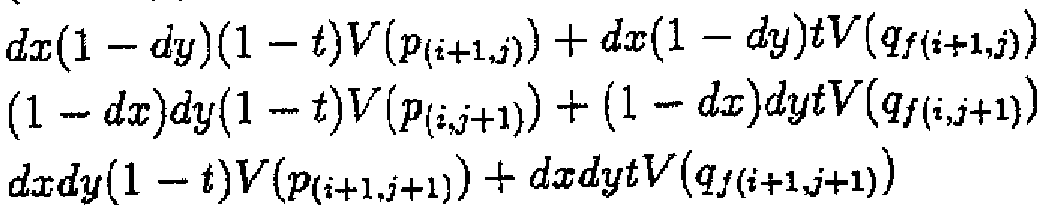
- FIG. 14 is a diagram showing how the sub-mapping is determined at the first level. At the first level, each sub-image is composed of four pixels. In the figure, these four pixels are indicated by solid lines. Now, when searching for the corresponding point of point X of p (1 's ) in q (1 's ) , the following steps are taken.
- pixels A to D are virtual pixels that do not originally exist.
- Pixels A ′ to C ′ are virtual pixels and are assumed to be located at the same positions as pixels A to C, respectively.
- the candidates for the corresponding point x ′ may be limited to, for example, those in which the center of the pixel is included in an inherited quadrilateral. In the case of FIG. 14, all four pixels are candidates.
- FIG. 15 is a flowchart showing the details of S21 in FIG. According to this flowchart, for a given r ?, the submapping at the m-th level is determined. In determining the submapping, the base technology determines the optimal ⁇ independently for each submapping.
- C (n) usually decreases ff, but when r? Exceeds the optimal value, C (n) starts to increase. Then, when C (n) takes the minimum value, ff
- Fig. 17 can be considered as an enlarged view of the vicinity of zero on the horizontal axis in Fig. 4. Once ⁇ opt opt is determined, f (n) can be finally determined.
- the base technology various merits can be obtained.
- the problem of the conventional edge detection type technology can be solved.
- a priori knowledge of the outside of the object included in the image is not required, and automatic detection of corresponding points is realized.
- the special point filter the luminance and position of a specific point can be maintained even at a coarse level of resolution, which is extremely advantageous for object recognition, feature extraction, and image matching. As a result, it is possible to construct an image processing system that significantly reduces manual work.
- ⁇ is determined as the optimal parameter when E takes the minimum value.
- the mapping corresponding to the parameter is finally regarded as the optimal matching between the two images.
- the nomometer may be any of a, only a, two cases as in the base technology, and two or more cases. If the parameter is 3 or more, change it one by one and decide
- the pixel becomes 1Z4.
- the pixel becomes 1Z9.
- the singularity filter was changed as follows. First, HIS, which is said to best match human intuition, was used as the color space. But color When converting to luminance, instead of luminance I, luminance Y, which is said to be closest to the sensitivity of the human eye, was selected.
- sub-images five types are generated for each level. Note that the highest level sub-image matches the original image.
- a primary derivative edge detection filter is further used.
- This filter can be realized by convolution with an operator G.
- the two types of filters corresponding to the horizontal and vertical derivatives of the nth level image are expressed as follows.
- G is selected from the following operators in consideration of the force calculation speed, which can apply a general operator used for edge detection in image analysis, and the like.
- Equation 59 The image of Equation 59 is used for the energy due to the difference of the newly introduced luminance derivative (edge) in the energy function when calculating the Forward Stage, that is, the first submapping derivation stage described later.
- Equation 60 Since this value is always positive, a maximum value filter is used for multi-resolution processing.
- Equation 61 The image of Equation 61 is used to determine the calculation order when calculating the Forward Stage described later.
- FIG. 18 is a flowchart relating to an improvement in the calculation for determining the sub-mapping at the m-th level.
- mapping f (m 'S) is sequentially obtained by energy minimization.
- the derivation of the mapping f (m 'S) is described below.
- the energy to be minimized here is the sum of the energy C by the corresponding pixel value and the energy D by the smoothness of the mapping in the improved base technology.
- the energy C is the energy C due to the difference in brightness (in the base technology before the improvement described above).
- ⁇ (z,) C ⁇ (z,) + ⁇ ⁇ (, J) + eC (, J) ( Equation 6 3)
- Parametae the ⁇ and ⁇ is 0 or a real number, after the improved In technology, it is a constant.
- these parameters can be constants because the newly introduced
- the energy C depends on the coordinate and the resolution level regardless of the type s of the submap f (m 's ).
- the energy D the same energy as that of the base technology before the improvement is used.
- the force S that considers only adjacent pixels and the number of surrounding pixels to consider can be specified by the parameter d. So that it was improved.
- mapping g ( m's ) from the end image q to the start image is similarly calculated.
- Refinement Stage (S42) bidirectional mapping f (m, s) of the obtained in Forward Stage Contact and 'based on (s, more reasonable mapping f, (m g m)' Request s).
- energy minimization calculation is performed for the newly defined energy M! /.
- the energy M is composed of the degree of consistency M between the destination image and the mapping g of the source image, and the difference M between the original mapping and the minimum M.
- a mapping g '( m ' s) from the end image q to the start image p is obtained in a similar manner so as not to lose the symmetry.
- the mapping of surrounding points is used, so whether or not those points have already been calculated affects the energy. In other words, the accuracy of the whole mapping changes greatly depending on from which point to calculate in order. Therefore, the absolute value image of the edge is used. Since the edge part contains a large amount of information, When the absolute value is large, the mapping calculation is performed first. This has made it possible to obtain a very accurate mapping especially for an image such as a binary image.
- FIG. 19 shows the configuration and processing of a moving image encoding device and a moving image decoding device.
- the upper part of the figure relates to the encoding device, and the lower part relates to the decoding device.
- CPF Critical Point Filter of the base technology, that is, an image matching processor using a singular point filter. Calculates matching between key frames in pixel units and outputs corresponding point information. This information is output as a file.
- This file describes the force that each pixel of the source keyframe corresponds to any pixel of the destination keyframe. Therefore, a morphing image between two key frames can be obtained by interpolating the pixel positions and pixel values corresponding to these key frames based on this file. If this file is applied only to the source-side keyframe and the interpolation calculation is performed, a morphing image is obtained that simply moves each pixel of the source-side keyframe to the position of the corresponding pixel described in this file. Can be In this case, only the position is interpolated between the corresponding pixels.
- DE Differential Encoder A differential (error) encoder. The difference between two image frames is variable-length coded based on Huffman coding and other statistical methods.
- NR maskable Noise Reducer noise reducer.
- Human vision often cannot recognize subtle changes. For example, in a portion where luminance changes rapidly, that is, in a region where a component having a high luminance spatial frequency component is strong, an error in luminance change is not visually recognized. Noise is superimposed on video information in various forms, and such data is simply visually recognized as noise and has no meaning as an image. Ignoring such visually meaningless random information, or “visual mask information”, results in higher compression ratios. Is important to achieve.
- Quantization in the current block matching uses visual mask information on luminance values, but there are some visual mask information other than luminance values.
- NR utilizes visual masks for spatial location information as well as temporal location information.
- the spatial position information visual mask makes use of the fact that the phase component of the spatial frequency is difficult to visually recognize in the case of an image with a complex luminance change.
- the visual mask of the time position information utilizes the fact that, even if the change in the time direction is severe and the change in the data is shifted in the time direction, the difference is hardly recognized visually. In these, the deviation is detected by comparing with a predetermined threshold value.
- DD Differential Decoder Differential (error) decoder. Decodes the difference coded by DE and adds it to the image frame in which the difference occurred, thereby improving the accuracy of the image frame
- F0 and the like indicate each frame of the moving image to be processed
- M0-4 indicates corresponding point information between F0 and F4 generated by the CPF.
- the pixel shifter Moving a pixel included in the first key frame (F0) to generate a virtual second key frame (F4,);
- the output destination may be a recording medium or a transmission medium. Actually, it is integrated with the information output in j) described later, and is output to a recording medium or the like as moving image encoded data.
- g) Matching is calculated by CPF between the second and third key frames (F4, F8) sandwiching one or more image frames (F5 to F7), and the corresponding point information between the second and third key frames ( Generating M4 8).
- the pixel shifter moves the pixels included in the improved virtual second keyframe (F4 ").
- the steps e) to j) described above are sequentially repeated for a further subsequent key frame as shown in frame F9 and the subsequent steps in FIG.
- the group end key frame is equivalent to a 1G OP end frame in MPEG. Therefore, the frame following this frame is newly regarded as the first key frame as the first frame of the new group, and the following processing a) is repeated.
- a group for a group corresponding to a GOP in MPEG (hereinafter simply referred to as a group), only one image corresponding to a key frame (I picture in MPEG) has to be encoded and transmitted.
- Decoding proceeds according to the following procedure.
- Steps to get Acquisition may be from either a transmission medium or a recording medium.
- the image shifter moves the pixels included in the first keyframe (F0) to create a virtual second keyframe. Generating (F4,).
- a virtual second key frame (F4 ') is generated by the same processing in advance, and the difference between this and the actual second key frame (F4) on the encoding side is Generating the compressed encoded data ( ⁇ 4) of the compressed data.
- INT Based on the corresponding point information (M0-4) between the first and second keyframes, INT allows the first keyframe (F0) and the improved virtual second keyframe (F4 ") to be Perform interpolation calculation Thereby generating intermediate frames (Fl "to F3") to be present between these key frames (FO, F4 ").
- the first key frame (FO), the generated intermediate frames (F1 "to F3"), and the improved virtual second key frame (F4 ") are used as decoded data between these key frames as a display device, etc. Step to output to.
- the pixel shifter moves the pixels included in the improved virtual second key frame (F4 ").
- a virtual third key frame (F8,) is also generated on the encoding side, and this is combined with the actual third key frame (F8) on the encoding side.
- V Based on the corresponding point information between the second and third keyframes (M4-8), the virtual second keyframe (F4 ") improved by INT and the virtual third keyframe improved by INT Generating intermediate frames (F5, to F7,) to be present between these key frames by interpolating between (F8 ").
- the enhanced virtual second key frame (F4 "), the generated intermediate frames (F5 'to F7,), and the enhanced virtual third key frame (F8 ,,) F4 ", F8") A step of outputting to a display device or the like as decoded data.
- this coding method does not use block matching, so that even if the compression ratio is increased, there is no block noise which is a problem in MPEG. Of course, even in image matching other than CPF, block noise should be used.
- the encoding device can be configured with an image matching processor, a differential encoder with a noise reduction function, a differential decoder, and a pixel shifter, and is simple. Also, the noise reduction function is an optional function, and need not be provided. Similarly, the decoding device can be composed of an interpolation processor, a differential decoder, and a pixel shifter, and is simple. In particular, the decoding device has a small amount of processing without having to perform image matching.
- this method may express a force corresponding point information file as a function of time, which ultimately improves the matching accuracy between F0 and F4.
- the partial files may be provided to the decryption side as the corresponding point information files without combining the four files.
- the decoding side can generate a more accurate video by repeating the process of generating Fl from FO, F4, and MO and generating F2 from FO, F4, MO, and Ml.
- Another embodiment of the present invention relates to the encoding device of FIG.
- image matching energy is introduced as a measure of the accuracy of image matching, and is used for noise reduction in DE + NR.
- FIG. 19 the features and functions not specifically described with reference to FIG. 19 are the same as those of the first embodiment.
- the matching energy here is determined by the difference between the distance between corresponding points and the pixel value, and is shown, for example, in Expression 49 in the base technology.
- the matching energy obtained at the time of image matching in the CPF is used as a by-product.
- the image matching of the base technology for each pixel between key frames, the pixel having the minimum mapping energy is detected as a corresponding point. Focusing on these characteristics of the underlying technology, good matching is achieved for pixels with low matching energy, while for locations with high matching energy, the positions and pixel values change naturally between key frames. Force that should have been a pixel In some cases, it can be evaluated that there may have been a matching error. As will be described in detail below, in the present embodiment, the compression ratio of the difference is increased for a portion having high matching accuracy. In another example, difference information on pixels for which a matching error is estimated may be highly compressed.
- the CPF when the CPF calculates the matching between the first and second key frames, the CPF also obtains the matching energy of each pixel corresponding between the two frames, and obtains the first matching energy. Generate an energy map describing the matching energy of each pixel on a key frame (FO). Similarly, an energy map is generated between other adjacent key frames. In other words, the energy map is the corresponding point between keyframes.
- Each matching energy is basically data describing each pixel of the previous key frame. The energy map may be displayed on a later key frame among the preceding and following key frames. The energy map is sent from CPF to DE + NR by a route not shown.
- DE + NR evaluates the quality of matching between key frames using this energy map, and adaptively compresses and encodes the difference between a virtual key frame and a real key frame based on the evaluation.
- the corresponding point information file is also sent to the DE + NR via a path (not shown).
- FIG. 20 is a diagram showing the configuration of DE + NR in FIG. 19 according to the present embodiment.
- + NR includes a difference calculator 10, a difference compression unit 12, an energy acquisition unit 14, and a determination unit 16. Of these, the former two correspond exclusively to DE, and the latter two correspond exclusively to NR.
- DE + NR a force explaining the operation of DE + NR when the first key frame (F0), the second key frame (F4), and the intermediate image frames (F1 to F3) are encoded.
- the operation of DE + NR is the same in the encoding of an image frame.
- the difference calculator 10 acquires the actual second key frame (F4) and the virtual second key frame (F4,), and calculates the difference between the pixel values of the pixels that correspond in position. As a result, a kind of image in which each pixel has a difference in pixel value between the two key frames is formed, and this is called a difference image.
- the difference image is sent to the energy acquisition unit 14.
- the energy acquisition unit 14 also inputs the energy map between the actual first key frame (F0) and the actual second key frame (F4) and the corresponding point information (M0-4) force. Is done.
- the energy obtaining unit 14 obtains the matching energy of the difference image using these.
- the acquiring unit 14 acquires corresponding point information (M0-4) between the first and second key frames from the CPF.
- the difference image power follows the virtual second key frame (F4,) and the first key frame (F0), so that the pixels of the difference image become the pixels of the first key frame (F0). Acquire the force and the correspondence that correspond to the shifted one.
- the matching energy of the pixel on the first key frame (F0) corresponding to each pixel of the difference image is calculated as the difference image Is obtained as the matching energy of each pixel.
- the matching energy of the difference image is thus obtained.
- the energy acquisition unit 14 sends the matching energy of the difference image to the determination unit 16.
- the determining unit 16 uses the matching energy of each pixel of the differential image to determine a high compression target region in the differential image, and notifies the compressing unit 12 of information on a force to which any region should be highly compressed.
- the determination is performed, for example, as follows.
- the determination unit 16 divides the difference image into blocks of 16 ⁇ 16 pixels, and compares the matching energy of all the pixels included in each block with a predetermined threshold. As a result of the comparison, if the matching energy of all the pixels in the block is less than or equal to the threshold value, the area is determined to be the high compression target block.
- the compression unit 12 compresses the difference image in a JPEG format.
- the compression ratio is adaptively changed between the normal region and the high-compression corresponding region using the information on the high-compression corresponding region notified from the determination unit 16.
- processing that makes the quantization width of the DCT coefficient larger than that of a normal block can be used.
- a process of applying JPEG compression may be performed after setting the pixel value of the high compression target block to 0.
- the reason why the region with low matching energy is highly compressed is as follows.
- a pixel having a low matching energy can be regarded as having a good matching result between key frames. Therefore, in the difference image where the matching energy is low, the difference between the actual second key frame (F4) and the virtual second key frame (F4 ') is different from the original one. If so, it can be considered noise. Therefore, a region having a low matching energy in the difference image can be significantly compressed as compared with other regions which do not care about information loss due to high compression. On the other hand, in the region where the matching energy is large, an error may have occurred in the matching, and the difference between the virtual second key frame (F4,) and the actual second key frame (F4) is important in decoding. Therefore, the compression ratio is kept low and the decoding accuracy is given priority.
- the compression unit 18 outputs the compression-encoded difference ( ⁇ 4) between the actual second key frame (F4) and the virtual second key frame (F4 ′).
- Code according to the present embodiment the difference information between the real key frame and the virtual key frame can be adaptively compressed according to the importance of performing accurate decoding of the encoded image more faithfully to the original image.
- high encoding efficiency can be realized while maintaining decoding accuracy.
- the significance is, of course, that the present embodiment can also enjoy the advantages of the first embodiment.
- DE + NR compares the matching energy of each pixel in the second key frame (F4) with, for example, the average of the matching energies of the other pixels in the 9 ⁇ 9 pixel block centered on itself. If the result of the comparison indicates that the difference between the two exceeds a predetermined threshold value, ie, V, then such a pixel may be determined to cause a matching error.
- a predetermined threshold value ie, V
- Corresponding information causing an error can be considered to be meaningless data for the decoding side, and the difference information between the actual second key frame (F4) and the virtual second key frame (F4,) can be considered.
- data on a pixel having a matching error can be called noise. This eliminates the need to consider information loss due to high compression, and the DE + NR is the difference image between the real key frame and the virtual key frame, and the pixel corresponding to the matching error between the real key frames. Is compressed at a higher rate than other pixels.
- the matching error is determined, for example, by comparing the tendency of the motion vector of the surrounding pixel with the tendency of the motion vector of the pixel of interest to determine whether the motion vector of the pixel of interest is significantly different from the surrounding tendency. You may do it with.
- the intermediate frames (F1 to F3) between the first and second key frames (FO, F4) are taken into consideration, and the adjacent frames of all these image frames are considered.
- a matching is calculated to generate corresponding point information files (MO to M3), and those are integrated to make one-to-one correspondence between the first and second key frames (FO, F1).
- Deformation technology to obtain two corresponding point information files is conceivable.
- this modification technique it is possible to calculate matching energy between image frames and apply the calculated energy to scene change detection and the like.
- the configuration related to scene change detection is as follows.
- the CPF performs matching calculations for each set of FO and Fl, F1 and F2, F2 and F3, F3 and F4 ' I do.
- the average of the matching energies of the pixels of an entire image frame is compared with a predetermined threshold for scene change detection, and the image immediately after that is regarded as a new group.
- a predetermined threshold for scene change detection For example, based on the energy map # 5 between F5 and F6, it is assumed that as a result of averaging the matching energies of the respective pixels of F5 relating to the matching of F5 and F6, the value exceeds the key frame addition threshold value.
- the immediately following key frame that is, F6 and below, may be a new group, and F6 may be the first key frame of the next group. This is because if the matching energy is large, it can be considered that there has been a large change between the images. This makes it possible to automatically detect scene changes and to select groups in response to scene changes.
- the average matching energy of the pixels in each image frame is calculated and added cumulatively, and when the value exceeds a predetermined threshold value,
- the image frame may be newly registered as a key frame. This is because if a key frame can be added when the accumulated amount of change between image frames exceeds a certain value, the image quality at the time of decoding will be further improved.
- the present invention can be used for compression encoding and decoding of moving images.
Landscapes
- Engineering & Computer Science (AREA)
- Multimedia (AREA)
- Signal Processing (AREA)
- Compression Or Coding Systems Of Tv Signals (AREA)
- Compression, Expansion, Code Conversion, And Decoders (AREA)
Abstract
Description


Claims
Priority Applications (3)
| Application Number | Priority Date | Filing Date | Title |
|---|---|---|---|
| EP05727896A EP1765020A4 (en) | 2004-06-14 | 2005-03-29 | METHOD FOR ENCODING MOVING IMAGES AND METHOD FOR DECODING MOVING IMAGES |
| JP2006514417A JPWO2005122593A1 (ja) | 2004-06-14 | 2005-03-29 | 動画符号化方法および動画復号方法 |
| US11/547,289 US20070206672A1 (en) | 2004-06-14 | 2005-03-29 | Motion Image Encoding And Decoding Method |
Applications Claiming Priority (2)
| Application Number | Priority Date | Filing Date | Title |
|---|---|---|---|
| JP2004-175979 | 2004-06-14 | ||
| JP2004175979 | 2004-06-14 |
Publications (1)
| Publication Number | Publication Date |
|---|---|
| WO2005122593A1 true WO2005122593A1 (ja) | 2005-12-22 |
Family
ID=35503519
Family Applications (1)
| Application Number | Title | Priority Date | Filing Date |
|---|---|---|---|
| PCT/JP2005/005941 Ceased WO2005122593A1 (ja) | 2004-06-14 | 2005-03-29 | 動画符号化方法および動画復号方法 |
Country Status (7)
| Country | Link |
|---|---|
| US (1) | US20070206672A1 (ja) |
| EP (1) | EP1765020A4 (ja) |
| JP (1) | JPWO2005122593A1 (ja) |
| KR (1) | KR20070026515A (ja) |
| CN (1) | CN1957616A (ja) |
| TW (1) | TW200612756A (ja) |
| WO (1) | WO2005122593A1 (ja) |
Cited By (2)
| Publication number | Priority date | Publication date | Assignee | Title |
|---|---|---|---|---|
| WO2007129436A1 (ja) * | 2006-04-18 | 2007-11-15 | Monolith Co., Ltd. | 画像圧縮方法、画像圧縮装置、および動画符号化方法 |
| GB2520840A (en) * | 2010-10-01 | 2015-06-03 | Trust Battery Ireland Ltd | Detection of radio frequency emissions |
Families Citing this family (11)
| Publication number | Priority date | Publication date | Assignee | Title |
|---|---|---|---|---|
| JP2007192919A (ja) * | 2006-01-17 | 2007-08-02 | Olympus Corp | 画像表示装置 |
| US10027478B2 (en) * | 2007-10-09 | 2018-07-17 | International Business Machines Corporation | Differential key backup |
| TWI424360B (zh) * | 2007-12-31 | 2014-01-21 | Altek Corp | Multi-directional face detection method |
| US8300964B2 (en) * | 2008-08-07 | 2012-10-30 | Apteryx Inc. | System and method for preparing spatially related medical digital image data sets for image compression and storage prior to image reconstruction |
| EP2330817B1 (en) * | 2008-09-04 | 2016-08-31 | Japan Science and Technology Agency | Video signal converting system |
| CA3052614C (en) * | 2010-09-30 | 2021-03-09 | Mitsubishi Electric Corporation | Moving image encoding device, moving image decoding device, moving image coding method, and moving image decoding method |
| US9578333B2 (en) * | 2013-03-15 | 2017-02-21 | Qualcomm Incorporated | Method for decreasing the bit rate needed to transmit videos over a network by dropping video frames |
| US10621446B2 (en) * | 2016-12-22 | 2020-04-14 | Texas Instruments Incorporated | Handling perspective magnification in optical flow processing |
| CN115499666B (zh) * | 2022-11-18 | 2023-03-24 | 腾讯科技(深圳)有限公司 | 视频的压缩方法、解压缩方法、装置、设备和存储介质 |
| KR102738639B1 (ko) * | 2022-12-23 | 2024-12-05 | 한국전자기술연구원 | 데이터 특성 분류에 따른 분류 기반 동영상 프레임 율 변환 방법 및 장치 |
| US12120311B2 (en) * | 2023-02-08 | 2024-10-15 | Realtek Semiconductor Corp. | Encoder and associated signal processing method |
Citations (3)
| Publication number | Priority date | Publication date | Assignee | Title |
|---|---|---|---|---|
| JPH08107558A (ja) * | 1994-10-07 | 1996-04-23 | Nec Corp | 動画符号化および復号の方法および装置 |
| JPH10304374A (ja) * | 1997-04-25 | 1998-11-13 | Sharp Corp | 動画像符号化装置 |
| JP2001128179A (ja) * | 1999-10-26 | 2001-05-11 | Nec Corp | 動画像符号化装置および方法 |
Family Cites Families (7)
| Publication number | Priority date | Publication date | Assignee | Title |
|---|---|---|---|---|
| AU657510B2 (en) * | 1991-05-24 | 1995-03-16 | Apple Inc. | Improved image encoding/decoding method and apparatus |
| JPH0787482A (ja) * | 1993-09-17 | 1995-03-31 | Fujitsu Ltd | 画像データの符号化方法及び復元方法並びに装置 |
| US6567469B1 (en) * | 2000-03-23 | 2003-05-20 | Koninklijke Philips Electronics N.V. | Motion estimation algorithm suitable for H.261 videoconferencing applications |
| US6842483B1 (en) * | 2000-09-11 | 2005-01-11 | The Hong Kong University Of Science And Technology | Device, method and digital video encoder for block-matching motion estimation |
| JP3859989B2 (ja) * | 2000-10-30 | 2006-12-20 | 株式会社モノリス | 画像マッチング方法およびその方法を利用可能な画像処理方法と装置 |
| JP4050472B2 (ja) * | 2001-02-06 | 2008-02-20 | 株式会社モノリス | 画像生成方法、装置およびシステム |
| JP2003018602A (ja) * | 2001-04-24 | 2003-01-17 | Monolith Co Ltd | 画像データ符号化および復号のための方法および装置 |
-
2005
- 2005-03-29 EP EP05727896A patent/EP1765020A4/en not_active Withdrawn
- 2005-03-29 CN CNA2005800164195A patent/CN1957616A/zh active Pending
- 2005-03-29 JP JP2006514417A patent/JPWO2005122593A1/ja active Pending
- 2005-03-29 KR KR1020067024383A patent/KR20070026515A/ko not_active Ceased
- 2005-03-29 US US11/547,289 patent/US20070206672A1/en not_active Abandoned
- 2005-03-29 WO PCT/JP2005/005941 patent/WO2005122593A1/ja not_active Ceased
- 2005-03-31 TW TW094110394A patent/TW200612756A/zh unknown
Patent Citations (3)
| Publication number | Priority date | Publication date | Assignee | Title |
|---|---|---|---|---|
| JPH08107558A (ja) * | 1994-10-07 | 1996-04-23 | Nec Corp | 動画符号化および復号の方法および装置 |
| JPH10304374A (ja) * | 1997-04-25 | 1998-11-13 | Sharp Corp | 動画像符号化装置 |
| JP2001128179A (ja) * | 1999-10-26 | 2001-05-11 | Nec Corp | 動画像符号化装置および方法 |
Cited By (2)
| Publication number | Priority date | Publication date | Assignee | Title |
|---|---|---|---|---|
| WO2007129436A1 (ja) * | 2006-04-18 | 2007-11-15 | Monolith Co., Ltd. | 画像圧縮方法、画像圧縮装置、および動画符号化方法 |
| GB2520840A (en) * | 2010-10-01 | 2015-06-03 | Trust Battery Ireland Ltd | Detection of radio frequency emissions |
Also Published As
| Publication number | Publication date |
|---|---|
| EP1765020A1 (en) | 2007-03-21 |
| EP1765020A4 (en) | 2010-10-06 |
| CN1957616A (zh) | 2007-05-02 |
| TW200612756A (en) | 2006-04-16 |
| JPWO2005122593A1 (ja) | 2008-04-10 |
| KR20070026515A (ko) | 2007-03-08 |
| US20070206672A1 (en) | 2007-09-06 |
Similar Documents
| Publication | Publication Date | Title |
|---|---|---|
| JP3889233B2 (ja) | 画像符号化方法と装置および画像復号方法と装置 | |
| JP2008252860A (ja) | 画像処理方法及び画像処理装置 | |
| JP2008282376A (ja) | 画像処理方法および装置 | |
| WO2005122593A1 (ja) | 動画符号化方法および動画復号方法 | |
| US20030076881A1 (en) | Method and apparatus for coding and decoding image data | |
| JP2004040422A (ja) | 画像処理方法と装置 | |
| JP4050472B2 (ja) | 画像生成方法、装置およびシステム | |
| JP4157686B2 (ja) | 画像符号化および復号のための方法および装置 | |
| JP4039858B2 (ja) | 画像マッチング方法と装置、および画像符号化方法と装置 | |
| JP2003037842A (ja) | 画像符号化方法、復号方法および画像符号化装置、復号装置 | |
| JP2007122751A (ja) | 画像処理のための方法、装置、プログラム | |
| WO2007072543A1 (ja) | 動画符号化方法 | |
| JP3827981B2 (ja) | 画像符号化方法と装置および画像復号方法と装置 | |
| JP4524412B2 (ja) | 画像符号化方法、復号方法および画像符号化装置、復号装置 | |
| JP3839353B2 (ja) | 画像符号化方法と装置および画像復号方法および装置 | |
| JP2003274399A (ja) | 画像符号化方法と装置、画像復号方法と装置 | |
| WO2007129436A1 (ja) | 画像圧縮方法、画像圧縮装置、および動画符号化方法 | |
| JPWO2007069350A1 (ja) | 画像符号化および復号の方法と装置 | |
| WO2007069320A1 (ja) | 動画符号化方法および動画復号方法 | |
| JP3773417B2 (ja) | 画像データ符号化および復号のための方法および装置 | |
| JP2003032687A (ja) | 画像処理方法および装置 | |
| JP2004048595A (ja) | 画像符号化方法および装置 | |
| EP1294191A2 (en) | Image processing method and apparatus | |
| JP2004048496A (ja) | 画像符号化方法および装置、画像復号方法および装置と、画像配信装置 | |
| JP2007174690A (ja) | 画像符号化方法、画像復号方法、画像符号化装置および画像復号装置 |
Legal Events
| Date | Code | Title | Description |
|---|---|---|---|
| AK | Designated states |
Kind code of ref document: A1 Designated state(s): AE AG AL AM AT AU AZ BA BB BG BR BW BY BZ CA CH CN CO CR CU CZ DE DK DM DZ EC EE EG ES FI GB GD GE GH GM HR HU ID IL IN IS JP KE KG KP KR KZ LC LK LR LS LT LU LV MA MD MG MK MN MW MX MZ NA NI NO NZ OM PG PH PL PT RO RU SC SD SE SG SK SL SM SY TJ TM TN TR TT TZ UA UG US UZ VC VN YU ZA ZM ZW |
|
| AL | Designated countries for regional patents |
Kind code of ref document: A1 Designated state(s): BW GH GM KE LS MW MZ NA SD SL SZ TZ UG ZM ZW AM AZ BY KG KZ MD RU TJ TM AT BE BG CH CY CZ DE DK EE ES FI FR GB GR HU IE IS IT LT LU MC NL PL PT RO SE SI SK TR BF BJ CF CG CI CM GA GN GQ GW ML MR NE SN TD TG |
|
| 121 | Ep: the epo has been informed by wipo that ep was designated in this application | ||
| WWE | Wipo information: entry into national phase |
Ref document number: 2006514417 Country of ref document: JP |
|
| WWE | Wipo information: entry into national phase |
Ref document number: 11547289 Country of ref document: US Ref document number: 2007206672 Country of ref document: US |
|
| WWE | Wipo information: entry into national phase |
Ref document number: 1020067024383 Country of ref document: KR |
|
| WWE | Wipo information: entry into national phase |
Ref document number: 200580016419.5 Country of ref document: CN |
|
| WWE | Wipo information: entry into national phase |
Ref document number: 2005727896 Country of ref document: EP |
|
| NENP | Non-entry into the national phase |
Ref country code: DE |
|
| WWW | Wipo information: withdrawn in national office |
Ref document number: DE |
|
| WWP | Wipo information: published in national office |
Ref document number: 1020067024383 Country of ref document: KR |
|
| WWP | Wipo information: published in national office |
Ref document number: 2005727896 Country of ref document: EP |
|
| WWP | Wipo information: published in national office |
Ref document number: 11547289 Country of ref document: US |