WO2006046465A1 - 対物レンズ、光ピックアップ装置及び光ディスクドライブ装置 - Google Patents
対物レンズ、光ピックアップ装置及び光ディスクドライブ装置 Download PDFInfo
- Publication number
- WO2006046465A1 WO2006046465A1 PCT/JP2005/019300 JP2005019300W WO2006046465A1 WO 2006046465 A1 WO2006046465 A1 WO 2006046465A1 JP 2005019300 W JP2005019300 W JP 2005019300W WO 2006046465 A1 WO2006046465 A1 WO 2006046465A1
- Authority
- WO
- WIPO (PCT)
- Prior art keywords
- objective lens
- wavelength
- information recording
- optical
- light
- Prior art date
- Legal status (The legal status is an assumption and is not a legal conclusion. Google has not performed a legal analysis and makes no representation as to the accuracy of the status listed.)
- Ceased
Links
Classifications
-
- G—PHYSICS
- G11—INFORMATION STORAGE
- G11B—INFORMATION STORAGE BASED ON RELATIVE MOVEMENT BETWEEN RECORD CARRIER AND TRANSDUCER
- G11B7/00—Recording or reproducing by optical means, e.g. recording using a thermal beam of optical radiation by modifying optical properties or the physical structure, reproducing using an optical beam at lower power by sensing optical properties; Record carriers therefor
- G11B7/12—Heads, e.g. forming of the optical beam spot or modulation of the optical beam
- G11B7/135—Means for guiding the beam from the source to the record carrier or from the record carrier to the detector
- G11B7/1372—Lenses
- G11B7/1374—Objective lenses
-
- G—PHYSICS
- G02—OPTICS
- G02B—OPTICAL ELEMENTS, SYSTEMS OR APPARATUS
- G02B13/00—Optical objectives specially designed for the purposes specified below
-
- G—PHYSICS
- G02—OPTICS
- G02B—OPTICAL ELEMENTS, SYSTEMS OR APPARATUS
- G02B5/00—Optical elements other than lenses
- G02B5/18—Diffraction gratings
-
- G—PHYSICS
- G11—INFORMATION STORAGE
- G11B—INFORMATION STORAGE BASED ON RELATIVE MOVEMENT BETWEEN RECORD CARRIER AND TRANSDUCER
- G11B7/00—Recording or reproducing by optical means, e.g. recording using a thermal beam of optical radiation by modifying optical properties or the physical structure, reproducing using an optical beam at lower power by sensing optical properties; Record carriers therefor
- G11B7/12—Heads, e.g. forming of the optical beam spot or modulation of the optical beam
- G11B7/135—Means for guiding the beam from the source to the record carrier or from the record carrier to the detector
- G11B7/1353—Diffractive elements, e.g. holograms or gratings
-
- G—PHYSICS
- G11—INFORMATION STORAGE
- G11B—INFORMATION STORAGE BASED ON RELATIVE MOVEMENT BETWEEN RECORD CARRIER AND TRANSDUCER
- G11B7/00—Recording or reproducing by optical means, e.g. recording using a thermal beam of optical radiation by modifying optical properties or the physical structure, reproducing using an optical beam at lower power by sensing optical properties; Record carriers therefor
- G11B7/12—Heads, e.g. forming of the optical beam spot or modulation of the optical beam
- G11B7/135—Means for guiding the beam from the source to the record carrier or from the record carrier to the detector
- G11B7/1392—Means for controlling the beam wavefront, e.g. for correction of aberration
- G11B7/13922—Means for controlling the beam wavefront, e.g. for correction of aberration passive
-
- G—PHYSICS
- G11—INFORMATION STORAGE
- G11B—INFORMATION STORAGE BASED ON RELATIVE MOVEMENT BETWEEN RECORD CARRIER AND TRANSDUCER
- G11B7/00—Recording or reproducing by optical means, e.g. recording using a thermal beam of optical radiation by modifying optical properties or the physical structure, reproducing using an optical beam at lower power by sensing optical properties; Record carriers therefor
- G11B7/12—Heads, e.g. forming of the optical beam spot or modulation of the optical beam
- G11B7/135—Means for guiding the beam from the source to the record carrier or from the record carrier to the detector
- G11B7/1392—Means for controlling the beam wavefront, e.g. for correction of aberration
- G11B7/13925—Means for controlling the beam wavefront, e.g. for correction of aberration active, e.g. controlled by electrical or mechanical means
-
- G—PHYSICS
- G11—INFORMATION STORAGE
- G11B—INFORMATION STORAGE BASED ON RELATIVE MOVEMENT BETWEEN RECORD CARRIER AND TRANSDUCER
- G11B7/00—Recording or reproducing by optical means, e.g. recording using a thermal beam of optical radiation by modifying optical properties or the physical structure, reproducing using an optical beam at lower power by sensing optical properties; Record carriers therefor
- G11B2007/0003—Recording, reproducing or erasing systems characterised by the structure or type of the carrier
- G11B2007/0006—Recording, reproducing or erasing systems characterised by the structure or type of the carrier adapted for scanning different types of carrier, e.g. CD & DVD
Definitions
- the present invention relates to an objective lens used in an optical pickup apparatus capable of recording and Z or reproducing information in a compatible manner with different types of optical information recording media, and an optical pickup apparatus and optical disc drive apparatus using the objective lens.
- an optical pickup apparatus and optical disc drive apparatus using the objective lens.
- laser light sources used as light sources for reproducing information recorded on optical discs and recording information on optical discs have become shorter, for example Laser light sources with wavelengths of 400 to 420 nm are being put into practical use, such as blue-violet semiconductor lasers and blue SHG lasers that convert the wavelength of infrared semiconductor lasers using the second harmonic.
- blue-violet laser light sources When these blue-violet laser light sources are used, it is possible to record 15 to 20 GB of information on an optical disk with a diameter of 12 cm when using an objective lens with the same numerical aperture (NA) as DVD (digital versatile disk). If the NA of the objective lens is increased to 0.85, 23 to 25 GB of information can be recorded on an optical disk with a diameter of 12 cm.
- NA numerical aperture
- an optical disk and a magneto-optical disk using a blue-violet laser light source are collectively referred to as a “high density optical disk”.
- the optical pickup device installed in the optical disc player Z recorder for high-density optical discs can provide appropriate information while maintaining compatibility with both high-density optical discs, DVDs, and even CDs. It is desirable to have the performance of recording Z playback.
- optical systems for high-density optical discs and DVDs can be used.
- a method of selectively switching information with the optical system for CDs according to the recording density of the optical disk to be played back can be considered, but since multiple optical systems are required, it is disadvantageous for miniaturization and cost. Will increase.
- an optical system for high-density optical discs and an optical system for DVDs and CDs are also used in compatible optical pickup devices. It is preferable to reduce the number of optical components constituting the optical pickup device as much as possible. It is most advantageous for simplification of the configuration of the optical pickup device and cost reduction to make the objective lens arranged opposite to the optical disk in common and to make this objective lens a single lens configuration. In order to obtain a common objective lens for a plurality of types of optical disks having different recording Z reproduction wavelengths, it is necessary to form a phase structure having the wavelength dependence of spherical aberration in the objective lens.
- Patent Document 1 discloses an objective lens having a single-lens configuration capable of recording, recording, or reproducing information in a manner compatible with a high-density optical disc, a DVD, and a CD.
- Patent Document 1 JP 2004-79146 A
- blue and D are obtained by using even-order diffracted light with respect to a light beam (hereinafter referred to as blue) emitted from a blue-violet laser light source for a high-density optical disk.
- Infrared laser light source power for VD Emission light flux (hereinafter referred to as red) and CD infrared laser light source (hereinafter referred to as infrared) have improved diffraction efficiency, but blue Therefore, the diffraction angle determined by the diffraction order X wavelength is approximately the same for blue and infrared, and the diffraction action is compatible with high-density optical discs and CDs. Difficult to achieve.
- the objective lens of the prior art is compatible with high-density optical discs and CDs by making the infrared light enter the divergent light.
- this compatibility method is There is a problem that the amount of coma generated when the objective lens is tracking driven is large and is not practical.
- the present invention has been made in consideration of the above-mentioned problems, and has three types of discs with different recording densities, including a high-density optical disc having a diffractive structure and using a blue-violet laser light source, a DVD, and a CD.
- a group of objective lenses that can appropriately perform recording and Z or reproduction of information, especially the amount of coma generated when the objective lens is tracking driven when using a CD is sufficiently small!
- An object of the present invention is to provide an optical pickup device and an optical disk drive device using the same.
- optical disks both optical information recording media that use a blue-violet semiconductor laser or a blue-violet SHG laser as a light source for information recording Z reproduction are collectively referred to as "high-density optical disks".
- the NAO. 85 objective optical system records and reproduces information.
- an optical disc having such a protective substrate on its information recording surface an optical disc having a protective film with a thickness of several to several tens of nm on the information recording surface, a protective substrate or a protective film.
- high-density optical disks include magneto-optical disks that use blue-violet semiconductor lasers or blue-violet SHG lasers as light sources for recording and reproducing information.
- DVD means DVD series such as DVD-ROM, DVD-Video, DVD-Audio, DVD—RAM ⁇ DVD-R, DVD—RW ⁇ DVD + R ⁇ DVD + RW, etc.
- CD is a generic term for CD optical discs such as CD-ROM, CD-Audio, CD-Video, CD-R, and CD-RW. Recording density is highest for high-density optical discs, followed by DVD and CD.
- the objective lens according to Item 1 wherein the first light beam having the first wavelength ⁇ 1 ( ⁇ l ⁇ 450 nm) emitted from the first light source is transmitted through the first protective substrate having the thickness tl.
- Information recording surface of optical information recording medium The second light flux of the second wavelength 2 (1.5 X ⁇ ⁇ ⁇ 2 ⁇ 1.7 ⁇ ⁇ ⁇ ) emitted from the second light source power is obtained by collecting and condensing the light on Is collected on the information recording surface of the second optical information recording medium through a second protective substrate having a thickness of t2 (tl ⁇ t2) to reproduce and Z or record information, and then exit from the third light source.
- the third light beam 3 (1.9 ⁇ ⁇ ⁇ ⁇ 3 ⁇ 2.
- the objective lens is connected to the first to third optical information recording media. It is an objective lens having a single lens configuration that is commonly used, and at least one optical surface of the objective lens includes a central region including an optical axis and a peripheral region surrounding the central region. Divided into at least two areas,
- a first diffractive structure is formed in the central region, and the objective lens emits diffracted lights of the same order among the diffracted lights of the first to third light beams generated by the first diffractive structure, respectively. Condensing on the information recording surfaces of the first to third optical information recording media;
- a second diffractive structure is formed in the peripheral region, and the objective lens outputs diffracted lights of different orders from the diffracted lights of the first and second light beams generated in the second diffractive structure, respectively. Condensed on the information recording surfaces of the first and second optical information recording media.
- a diffractive structure that generates diffracted light of the same diffraction order with respect to light beams of three different wavelengths (for example, blue, red, and infrared) is provided in the third optical information recording medium.
- the third optical information recording medium By forming it in the central region corresponding to the numerical aperture of (for example, CD), the first optical information recording medium (for example, high-density optical disk) and the third optical information recording medium (for example, CD)
- an appropriate condensing spot is formed on the information recording surface.
- the number of regions is not limited to two, and the central region may be further divided into a plurality of regions, or the peripheral region may be further divided into a plurality of regions. .
- Recording ⁇ Depending on the number of optical information recording media to be reproduced and the standards, the number of areas can be changed as appropriate so that the recording and reproduction characteristics for each optical information recording medium are optimal. Noh.
- the area corresponding to the numerical aperture of CD, the numerical aperture of CD, the area corresponding to the numerical aperture of DVD is preferably divided into four regions: a region corresponding to the numerical aperture of HD, and a region corresponding to the numerical aperture of BD from the numerical aperture of HD.
- FIG. 1 is a diagram schematically showing a configuration of an optical pickup device PU1.
- FIG. 2 is a diagram schematically showing a configuration of an objective lens OL.
- the diffraction efficiency for each wavelength in the central region can be set as appropriate according to the use of the optical pickup device on which the objective lens of the present invention is mounted.
- a first optical information recording medium for example, a high-density optical disk
- second and third optical information recording media for example, DVD and CD.
- the diffraction efficiency in the central region is focused on the light flux of wavelength ⁇ 1 (for example, blue).
- an optical pickup device that performs reproduction only on the first optical information recording medium (later high-density optical disk), and performs recording and Z or reproduction on the second and third optical information recording media (for example, DVD and CD).
- the diffraction efficiency in the central region is focused on a light flux having a wavelength of 2 or 3 (for example, red and infrared).
- the entire effective diameter of the luminous flux (for example, blue) having the wavelength ⁇ 1 is large.
- the decrease in diffraction efficiency in the central region does not have a significant effect.
- the second diffractive structure that generates diffracted light of different diffraction orders with light beams of wavelengths ⁇ 1 and ⁇ 2 (for example, blue and red) is formed in the peripheral region, that is, the third optical information recording medium (for example, CD ) In the region other than the central region corresponding to the number of apertures in (1) and (2), while ensuring high diffraction efficiency with respect to light beams with wavelengths ⁇ 1 and ⁇ 2 (for example, blue and red).
- Compatibility of optical information recording media for example, high density optical disc and DVD
- the objective lens according to the present invention has the same focal length, lens thickness and numerical aperture, is formed of the same material, and does not have the first and second diffractive structures. Measure separately in the central area and the peripheral area. At this time, the transmittance of the central region is measured by blocking the light beam incident on the peripheral region, and the transmittance of the peripheral region is measured by blocking the light beam incident on the central region.
- the range of selection of the ring zone depth when setting the diffraction efficiency for each wavelength of the central region is large, and can be applied to optical pickup devices for various uses.
- Objective lens can be provided.
- the objective lens described in Item 4 is the configuration described in Item 3, wherein the blazed wavelength of the first diffractive structure is a wavelength between the first wavelength ⁇ 1 and the second wavelength ⁇ 2. It is.
- the diffraction order of the central region is 1, assuming that the blazed wavelength is a wavelength between the first wavelength ⁇ 1 and the second wavelength 2, the wavelength of each wavelength according to the use of the optical pickup device The diffraction efficiency can be set.
- the objective lens according to Item 5 in the configuration according to any one of Items 1 to 4, is the first lens.
- the diffraction power of one diffraction structure is negative.
- the objective lens described in Item 6 is configured so that, in the second diffractive structure, the different orders are 2 in the first light flux and in the second light flux. It is 1.
- the diffraction order of the second diffractive structure is second order with the light flux with wavelength ⁇ 1 (eg blue) and first order with the light flux with wavelength ⁇ 2 (eg red)
- the diffraction efficiency of each wavelength is secured.
- the difference in the bending angle can be maximized, compatibility at a large pitch can be ensured, and loss of diffraction efficiency due to the shape error of the diffractive structure can be reduced.
- the blazed wavelength of the second diffractive structure is shorter than the first wavelength ⁇ 1.
- the blazed wavelength is changed to the first wavelength ⁇ A shorter wavelength than 1 is preferable.
- the objective lens according to Item 8 in the configuration according to Item 1, has the second diffractive structure in which a cross-sectional shape including an optical axis is a stepped shape including a plurality of level surfaces in a concentric shape.
- a wavelength-selective diffractive structure that is arranged and shifted by a height corresponding to the number of levels corresponding to the number of level planes for each predetermined number of level planes, and is different from each other in the second diffractive structure. The order is 0 for the first light flux and 1 for the second light flux.
- the phase of the second light beam can be controlled independently, and the spherical aberration with respect to the second light beam is excellent. Can be corrected. As a result, it is possible to provide an objective lens having excellent recording / reproducing characteristics for the second optical information recording medium.
- “Wavelength-selective diffractive structure” refers to a diffractive structure in which a predetermined number of steps are formed in each blaze and the cross-sectional shape including the optical axis of each blaze is stepped.
- the optical path difference added to the light flux ⁇ ⁇ ⁇ by the step formed in each blaze is an integral multiple of the wavelength of the light flux A, and the step in each blaze.
- the light beam A can be diffracted with a wavelength selectivity that diffracts the light beam B without being diffracted.
- the number of steps in the staircase shape, the height and width of the stairs, etc. are corrected It can be designed appropriately according to the amount and wavelength of spherical aberration. Specifically, it is described in JP-A-9 306018.
- the optical path difference added to the first wavelength ⁇ 1 by the step difference of one of the patterns in the second diffractive structure in the configuration according to Item 8 is Since it is twice the first wavelength ⁇ 1, the step for one wavelength-selective diffraction structure is set to a depth equivalent to twice the first wavelength ⁇ 1 in terms of optical path difference. Therefore, high diffraction efficiency (transmittance) can be secured for a light flux of any wavelength.
- the number of the predetermined level surfaces is any of 4, 5, and 6.
- the diffraction efficiency of a light beam that undergoes diffractive action also depends on the number of level surfaces that can be reached by a single step.
- the number of level surfaces is preferably 5.
- the peripheral area includes a first peripheral area surrounding the central area, and a first peripheral area surrounding the first peripheral area.
- the second diffractive structure is further divided into at least two regions of two peripheral regions, the second diffractive structure is formed in the first peripheral region, and the second peripheral region is not formed with the second diffractive structure, and is aspherical. Surface.
- a dedicated region through which only the light beam used for the first optical information recording medium (for example, a high-density optical disk) passes generally has a large aspherical inclination.
- transmittance loss occurs due to shading (vignetting of the light flux caused by an annular step). If this region is an aspherical surface on which no diffractive structure is formed, the transmittance of a light beam having a wavelength ⁇ 1 (eg, blue) can be increased.
- the objective lens according to Item 12 further includes a third diffractive structure, and the objective lens includes the third diffractive structure.
- the 10th-order diffracted light is collected on the information recording surface of the first optical information recording medium, and the diffracted light of the second light flux generated by the third diffractive structure Among them, the 6th-order diffracted light is condensed on the information recording surface of the second optical information recording medium, and the third diffractive structure
- the fifth-order diffracted light among the diffracted light of the third light beam generated in step 3 is condensed on the information recording surface of the third optical information recording medium.
- the diffraction order of the third diffractive structure is the 10th order for a light flux with a wavelength ⁇ 1 (eg blue), the 6th order for a light flux with a wavelength ⁇ 2 (eg red), and a light flux with a wavelength ⁇ 3 (eg infrared
- ⁇ 1 eg blue
- ⁇ 2 eg red
- ⁇ 3 eg infrared
- the objective lens has a high numerical aperture, spherical aberration fluctuation due to temperature change cannot be ignored. It becomes quantity. In particular, this spherical aberration fluctuation becomes a problem when the objective lens is made of resin.
- an objective lens having a wide usable temperature range can be provided.
- the objective lens described in Item 16 is made of resin in the configuration described in any one of Items 1 to 15.
- mass production can be performed at low cost with stable performance, and since it is lightweight, the power consumption of the actuator for focus driving and tracking driving can be reduced. Can be small. Further, since the viscosity in the molten state is low, it becomes possible to transfer the diffractive structure well by molding. In addition, it is preferable that an anti-oxidation agent is added to the resin, thereby improving the light resistance against blue.
- Asamaru resin is known as a material in which particles of 30 nm or less are dispersed in a base resin.
- Asamaru mal resin has a characteristic that the refractive index change with temperature change is small compared with that of ordinary optical applications, so the effect of improving temperature characteristics by the diffraction structure can be conserved. As a result, it is possible to reduce the deterioration of the wavelength characteristics due to the diffractive structure, to increase the design freedom of the optical element, and to increase the allowable range of manufacturing error and assembly accuracy.
- Dispersion of particles having a refractive index change rate accompanying a temperature change opposite to that of the resin and having a diameter of 30 ⁇ m or less in the resin allows the same moldability as that of the resin. While possessing, it is possible to obtain a dice material with a refractive index change rate with temperature change.
- An objective lens with a numerical aperture can be provided. Under the present circumstances, it is preferable that the said rosin satisfy
- the refractive index change accompanying the temperature change is expressed by the above formula 4 by differentiating the refractive index ⁇ with respect to the temperature t based on the Lorentz 'Lorentz equation.
- the contribution of the second term of the above formula is substantially increased by dispersing fine particles, preferably inorganic fine particles, in the resin. Let it counteract with changes caused by linear expansion.
- the same sign of the rate of change of the refractive index with temperature change is opposite to that of the resin, and particles having a diameter of 30 nm or less are dispersed in the resin to form the same molding as the resin.
- a material having a small change rate of refractive index with temperature change can be obtained.
- dnZdT of a thermoplastic resin has a negative value, that is, the refractive index decreases as the temperature increases. Therefore, in order to efficiently reduce I dn / dT I of the thermoplastic resin composition, it is preferable to disperse fine particles having a large dnZdT. Refractive index change rate dnZd
- T When T is large, if the sign of the refractive index change rate of the resin that is the base material is negative, the fine particles have a negative refractive index change rate that is closer to zero, and the sign is positive. This includes both the fact that fine particles have a certain refractive index change rate.
- thermoplastic resin composition By dispersing such fine particles in the thermoplastic resin, I dnZdT I of the thermoplastic resin composition can be effectively reduced in a small amount.
- conventional - 1. dnZdT was about 2 X 10_ 4, the absolute value 10 X 10_ 5 It is preferable to suppress to less than. And preferably 8 X 10_ less than 5, more preferably it is less than 6 X 1 0_ 5, optical design, or preferably as an optical element.
- the contribution of the second term can be further increased so as to have a temperature characteristic opposite to that of the initial grease. That is, it is possible to obtain a material whose refractive index increases instead of decreasing the refractive index as the temperature rises.
- the particles to be dispersed in the coconut resin are still inorganic materials.
- the inorganic material is an acid, and it is most preferable that the acid is in a saturated acid state.
- the oxide is in a saturated oxidation state, it is possible to prevent the progress of the acid action that causes deterioration of transmittance and wavefront aberration during blue irradiation.
- Being an inorganic substance is preferable because it is low in the reaction with the resin as a base material, which is a high molecular organic compound, and is preferred for an actual use such as laser light irradiation because it is an acid oxide.
- the accompanying deterioration can be prevented.
- the oxidation of the resin is likely to be accelerated.
- deterioration due to the acid will be prevented. I can do it.
- the dnZdT of the fine particles to be dispersed can be appropriately selected depending on the value of the dnZdT of the thermoplastic resin used as a base material.
- the fine particles are generally dispersed in the thermoplastic resin preferably used in an optical element. size, it is more preferred than 10 X 10_ 6 - is, DnZdT microparticles may be - 20 X 10_ is larger than 6 good Mashigu.
- the inorganic fine particles dispersed in the thermoplastic resin are not particularly limited, and the refractive index change rate power with temperature of the obtained thermoplastic resin composition can be achieved. It can be arbitrarily selected from fine particles. Specifically, oxide fine particles, metal salt fine particles, semiconductor fine particles, and the like are preferably used. Of these, those that do not generate absorption, light emission, fluorescence, etc. in the wavelength region used as an optical element are appropriately selected and used. It is preferable to do this.
- the metal constituting the metal oxide is Li, Na, Mg, Al, Si, K :, Ca, Sc, Ti, V, Cr, Mn, Fe, Co, Ni, Cu, Zn, Rb, Sr Y, Nb, Zr, Mo, Ag, Cd, In, Sn, Sb, Cs, Ba, La, Ta, Hf, W, Ir, Tl, Pb, Bi and one kind selected from the group consisting of rare earth metals or Two or more kinds of metal oxides can be used.
- rare earth oxides can also be used as the oxide fine particles used in the present invention, and specifically, scandium oxide, yttrium oxide, acid lanthanum oxide, cerium oxide, acid praseodymium, acid oxide. Examples thereof include neodymium, acid samarium, pyrium oxide, gadolinium oxide, terbium oxide, dysprosium oxide, holmium oxide, erbium oxide, yttrium oxide, ytterbium oxide, and lutetium oxide.
- the metal salt fine particles include carbonates, phosphates and sulfates, and specifically include calcium carbonate and aluminum phosphate.
- the semiconductor fine particles in the present invention mean fine particles having a semiconductor crystal composition
- specific examples of the semiconductor crystal composition include those of Group 14 elements of the periodic table such as carbon, silicon, germanium, and tin. Simple substance, Group 15 element of periodic table such as phosphorus (black phosphorus), Group 16 element of periodic table such as selenium, tellurium, etc.Group 14 element of multiple periodic tables such as carbide (SiC) Compound consisting of: tin (IV) (SnO), tin sulfide (IV, IV) (Sn (lD Sn (lV) S), sulfide
- Compounds of Group 12 elements of the periodic table and Group 16 elements of the periodic table (or II-VI compounds) such as cadmium iodide (CdTe), mercury sulfide (HgS), selenium-mercury (HgSe), tellurium-mercury (HgTe) Semiconductor), Arsenic Sulfide (
- periodic table group 15 element and periodic table group 16 element compound copper oxide (I) (Cu 0),
- Group 11 of the periodic table such as copper (I) (CuCl), copper bromide (I) (CuBr), copper iodide (I) (Cul), silver chloride (AgCl), silver bromide (A gBr)
- Group 10 elements of the periodic table such as acid nickel (II) (NiO), group 16 elements of the periodic table, cobalt oxide (II) (CoO),
- Periodic table of compounds of group 9 elements of periodic table such as cobalt (II) sulfide (CoS) and group 16 elements of periodic table, triiron tetroxide (Fe 2 O), iron (II) sulfide (FeS), etc.
- Group 8 elements and periodic table 1 such as copper (I) (CuCl), copper bromide (I) (CuBr), copper iodide (I) (Cul), silver chloride (AgCl), silver bromide (A gBr)
- Group 10 elements of the periodic table such as acid nickel (I
- Peripherals such as compounds with Group 16 elements, titanium oxide (TiO, TiO, TiO, TiO, etc.)
- a conductor cluster is illustrated similarly.
- fine particles having a large dnZdT for example, gallium nitride, zinc sulfide, zinc oxide zinc, lithium niobate, lithium tantalate and the like are preferably used.
- the base resin is suitably used as described in JP-A-2004-144951, JP-A-2004-144953, JP-A-2004-144954, and the like. Adopt well.
- the difference in refractive index between the thermoplastic resin and the dispersed fine particles is small, and that it is difficult to cause scattering when light is transmitted.
- the difference in refractive index between the thermoplastic resin and the dispersed fine particles is small, We discovered that even when large particles are used, the degree of light scattering is small.
- the difference in refractive index between the thermoplastic resin and the dispersed fine particles is preferably in the range of 0 to 0.3, and more preferably in the range of 0 to 0.15.
- the refractive index of a thermoplastic resin preferably used as an optical material is often about 1.4 to 1.6.
- a material to be dispersed in these thermoplastic resins for example, silica (oxidized) is used. (Carbon), calcium carbonate, aluminum phosphate, aluminum oxide, magnesium oxide, aluminum / magnesium oxide, etc. are preferably used.
- dnZdT of a thermoplastic resin composition can be effectively reduced by dispersing fine particles having a relatively low refractive index.
- the details of the reason why I dnZdT I of the thermoplastic resin composition in which fine particles with low refractive index are dispersed are small, the temperature change of the volume fraction of inorganic fine particles in the resin composition is not It is considered that the lower the refractive index of the fine particles, the smaller the I dn / dT I of the resin composition will be.
- fine particles with relatively low refractive index For example, silica (acid silicate), calcium carbonate, and aluminum phosphate are preferably used.
- thermoplastic resin composition It is difficult to simultaneously improve the dnZdT reduction effect, light transmittance, desired refractive index, and the like of the thermoplastic resin composition, and the fine particles dispersed in the thermoplastic resin are thermoplastic resin.
- the size of the dnZdT of the microparticles itself, the difference between the dnZdT of the microparticles and the dnZdT of the thermoplastic resin as the base material, the refractive index of the microparticles, etc. should be selected as appropriate. Can do.
- fine particles that are compatible with the thermoplastic resin as a base material that is, dispersibility with respect to the thermoplastic resin, and hardly cause scattering, to maintain light transmittance.
- silica is preferably used as fine particles for reducing I dn / dT I while maintaining light transmittance.
- the fine particles one kind of inorganic fine particles may be used, or a plurality of kinds of inorganic fine particles may be used in combination. By using a plurality of types of fine particles having different properties, the required properties can be improved more efficiently.
- the inorganic fine particles according to the present invention preferably have an average particle diameter of 1 nm or more and 30 nm or less, more preferably 1 nm or more and 20 nm or less, and further preferably 1 nm or more and lOnm or less. If the average particle size is less than lnm, it is difficult to disperse the inorganic fine particles and the desired performance may not be obtained. Therefore, the average particle size is preferably lnm or more. If it exceeds the upper limit, the resulting thermoplastic material composition may become turbid and the transparency may be lowered, and the light transmittance may be less than 70%. Therefore, the average particle size is preferably 30 ⁇ m or less.
- the average particle diameter here refers to the volume average value of the diameter (sphere equivalent particle diameter) when each particle is converted to a sphere having the same volume.
- the shape of the inorganic fine particles is not particularly limited, but spherical fine particles are preferably used.
- the minimum particle diameter minimum distance between the tangent lines when drawing two tangent lines that touch the outer circumference of the fine particle
- Z maximum diameter the corresponding value when drawing two tangent lines that touch the outer circumference of the fine particle
- the maximum value of the distance between tangents is 0.5 to 1.0. Force S is preferable, and 0.7 to 1.0 is still more preferable.
- the particle size distribution is not particularly limited, but the effects of the present invention can be obtained. In order to express more efficiently, those having a relatively narrow distribution are preferably used rather than those having a wide distribution.
- the mixing / dispersion of the resin and the base material is preferably performed in-line during the injection molding of the optical element. In other words, after mixing and dispersing, it is preferable not to cool and solidify until it is formed into an optical element (lens).
- the volume ratio between the resin and the particles is 9: 1 to 3: 2, so that a material having a small refractive index change rate with a change in temperature without impairing the moldability of the resin can be obtained. can get
- the objective lens according to Item 18, in the configuration according to any one of Items 1 to 15, is made of low-melting-point glass having a glass transition point of 400 ° C or lower.
- the first design magnification for the first wavelength ⁇ 1 is ml
- the second design for the second wavelength ⁇ 2 is used.
- the magnification is m2
- the third design magnification for the third wavelength 3 is m3
- the objective lens of the present invention uses the same order diffracted light at the first wavelength ⁇ 1 and the third wavelength 3 for compatibility with the first optical information recording medium and the third optical information recording medium.
- the magnification when using the three-optical information recording medium can be kept within the range of Equation (3), and good tracking characteristics can be obtained with a small amount of coma generated when the objective lens is driven for tracking.
- a first light source that emits a first light beam having a first wavelength ⁇ 1 ( ⁇ l ⁇ 450 nm) for reproducing and recording or recording information on a first optical information recording medium having a first protective substrate having a thickness tl. And second wavelength 2 (1.5 ⁇ 1 ⁇ 2 ⁇ 1.7 ⁇ 1) for reproducing and Z or recording information on a second optical information recording medium having a second protective substrate having a thickness t2 (tl ⁇ t2).
- a second light source that emits a second luminous flux;
- a third light beam emitting a third light beam 3 (1.9 ⁇ 1 ⁇ 3 ⁇ 2.IX ⁇ ) for reproducing and recording or recording information on a third optical information recording medium having a third protective substrate.
- Item 21. The objective lens according to any one of items 1 to 20, which collects the three light sources and the first to third light fluxes on the information recording surfaces of the first to third optical information recording media, respectively.
- the optical disk drive device includes the optical pickup device according to Item 21 and a moving device that moves the optical pickup device in the radial direction of each of the first to third optical information recording media. To do.
- the objective lens is arranged to face the optical information recording medium at the position closest to the optical information recording medium in a state where the optical information recording medium is mounted in the optical pickup device. It shall refer to the lens which has a condensing effect
- optical pickup device PU1 that can be used in the present embodiment can be incorporated in an optical disk drive device.
- FIG. 1 shows information recording appropriately for any of high-density optical discs BD, DVD, and CD.
- FIG. 2 is a diagram schematically showing a configuration of an optical pickup device PU1 that can perform Z reproduction.
- the combination of the wavelength, the thickness of the protective substrate, and the numerical aperture is not limited to this.
- the optical pickup device PU1 is a blue-violet semiconductor laser LD (first light source) that emits a 408 nm blue-violet laser beam (first beam) and emits a 408-nm blue-violet laser beam (first beam) when recording information on a BD.
- first light source a blue-violet semiconductor laser LD
- second emission point EP1 second light source
- Z playback a 658 nm laser beam
- a second emission point E P2 (third light source) that emits a 785 nm laser beam (third beam), a first light receiving unit DS1 that receives a reflected beam from the DVD information recording surface RL2, CD information recording surface 2nd light receiving part DS2 that receives the reflected light beam from RL3, light source module LM, prism PD and force PD, optical surface on the light source side is the optical axis Is divided into three areas: a central area including the first peripheral area surrounding the central area, and a second peripheral area surrounding the first peripheral area.
- the first diffractive structure is formed in the central region
- the second diffractive structure is formed in the first peripheral region
- the second peripheral region is an aspherical surface on which no diffractive structure is formed
- optical information A single-lens objective lens OL with a third diffractive structure formed on the optical surface on the recording medium side, 2-axis actuator AC1, 1-axis actuator AC2, and first through third beams pass in common.
- the first lens L1 which is arranged in the common optical path and can be shifted in the optical axis direction by the single-axis actuator AC2, the beam expander EXP, the first polarizing beam splitter BS1, 2-polarization beam splitter BS2, 1Z4 wavelength plate QWP, sensor lens SEN for adding astigmatism to the reflected light flux from the information recording surface RL1, and the first optical beam that is placed in a dedicated optical path through which only the first beam passes. Converts a single beam into a parallel beam The first collimator COL1, and the second collimator COL2 for converting the second light flux and the third light flux into a parallel light flux.
- a blue-violet SHG laser can be used as a BD light source.
- the optical axis of the first lens L1 is such that the first beam is emitted in a state of a beam expander EXP force parallel beam.
- the blue-violet semiconductor laser LD is emitted.
- the divergent light beam emitted from the blue-violet semiconductor laser LD1 is reflected by the first polarization beam splitter BS1, as shown by the solid line in FIG.
- the reflected light beam modulated by the information pits on the information recording surface RL1 is transmitted again through the objective lens OL, 1 Z4 wave plate QWP, beam expander EXP, and second polarization beam splitter BS2, and then converged by the first collimator COL1.
- Astigmatism is added by the sensor lens SEN and converges on the light receiving surface of the photodetector PD. Then, the information recorded on the BD can be read using the output signal of the photodetector PD.
- the first light beam is emitted so that the second light beam is emitted in a state of a parallel light beam.
- the first emission point EP1 is caused to emit light.
- the divergent light beam emitted from the first light emitting point EP1 is reflected by the prism PS and then converted into a parallel light beam by the second collimator COL2 as shown by the broken line in FIG.
- the objective lens OL After that, after being reflected by the second polarizing beam splitter BS2 and expanded by the beam expander EXP, it passes through the 1Z4 wave plate QWP and enters the objective lens OL in the state of parallel light.
- the spot is formed on the information recording surface RL2 through the protective substrate PL2.
- the objective lens OL A focused spot is formed on the information recording surface RL2 of the DVD by the light beam that has passed through the optical surface on the optical information recording medium side through the central region, the first peripheral region, and the optical information recording medium side.
- the objective lens OL is focused and tracked by the 2-axis actuator AC1 placed around it.
- the reflected light beam modulated by the information pits on the information recording surface RL2 is again transmitted through the objective lens OL, 1 Z4 wave plate QWP, and beam expander EXP, and then reflected by the second polarization beam splitter BS2 to be reflected by the first collimator COL2 Is converted into a convergent luminous flux. After that, the light is reflected twice in the prism and then converges on the first light receiving part DS1. Then, the information recorded on the DVD can be read using the output signal of the first light receiving unit DS1.
- the third beam is emitted so that the beam expander EXP force is a weakly divergent beam.
- the second emission point EP2 is caused to emit light.
- the divergent light beam emitted from the second light emitting point EP2 is reflected by the prism PS and then converted into a parallel light beam by the second collimator COL2 as shown by the dashed line in FIG.
- the objective lens OL After that, after being reflected by the second polarizing beam splitter BS 2 and expanded by the beam expander EXP, after passing through the 1Z4 wave plate QW P and entering the objective lens OL in the state of parallel light or weak finite divergent light, From there, it becomes a spot formed on the information recording surface RL3 via the CD protective substrate PL3. At this time, a condensing spot is formed on the information recording surface RL3 of the CD by the light beam that has passed through the central area of the objective lens OL and the optical surface on the optical information recording medium side.
- the objective lens OL is focused and tracked by the 2-axis actuator AC1 placed around it.
- the reflected light beam modulated by the information pits on the information recording surface RL3 is again transmitted through the objective lens OL, 1 Z4 wave plate QWP, and beam expander EXP, and then reflected by the second polarization beam splitter BS2 to be reflected by the first collimator COL2 Is converted into a convergent luminous flux. After that, the light is reflected twice in the prism and then converges on the second light receiving part DS2. Then, the information recorded on the CD can be read using the output signal of the second light receiving unit DS2.
- the optical surface SI on the source side includes three areas: a central area A1 including the optical axis, a first peripheral area A2 surrounding the central area, and a second peripheral area A3 surrounding the first peripheral area.
- the first diffractive structure 11 is formed in the central region A1
- the second diffractive structure 12 is formed in the first peripheral region A2
- the second peripheral region A3 is not formed with a diffractive structure. It is a spherical surface.
- the aspherical shape of the central region A1 and the shape of the first diffractive structure are determined so as to collect the first-order diffracted light of the first to third light beams on the information recording surface of each optical information recording medium. .
- the ring depth of the first diffractive structure 11 is determined so that the diffraction efficiency of the second light beam is 91% and the diffraction efficiency of the third light beam is 72%. Recording and playback with is possible.
- the aspherical shape of the first peripheral region A2 and the shape of the second diffraction structure are obtained by converting the 0th-order diffracted light (transmitted light) of the first light flux to BD.
- the optical information recording medium is focused on the information recording surface, and the first-order diffracted light (transmitted light) of the second light beam is focused on the information recording surface of the DVD optical information recording medium.
- the diffraction efficiency for each light beam of the second diffractive structure 12 is 100% for the first light beam and 88% for the second light beam, which is sufficiently high for both light beams. (Transmittance) is obtained.
- the aspherical shape of the second peripheral area A3 is determined so as to condense the first light flux on the information recording surface of the BD optical information recording medium.
- the diffractive structure is not formed in the second peripheral region, so that the vignetting of the light flux due to the annular zone step is prevented and the transmittance of the first light flux is improved.
- the design is focused on the diffraction efficiency of the second light flux and the third light flux, so the diffraction efficiency of the first light flux is 60%.
- the diffraction efficiency (transmittance) for the first light flux of the second diffractive structure 12 is set to 100% (that is, the expression (1) is satisfied), and the second peripheral region is an aspherical surface on which no diffractive structure is formed.
- the diffraction efficiency of the first light flux calculated by the area weighted average of each region is 86%, and recording and reproduction with respect to the BD can be performed at a high speed.
- the optical surface S2 on the optical information recording medium side has A third diffractive structure 13 is formed.
- the third diffractive structure 13 is a structure for compensating for variations in spherical aberration due to temperature changes.
- the third diffractive structure 13 has a spherical aberration that changes in the direction of insufficient correction. Has dependency.
- the first diffractive structure 11 is designed with an emphasis on the diffraction efficiency of the second and third light beams. It can be set as appropriate according to the application of the pickup device.
- the second diffractive structure 12 is a wavelength-selective diffractive structure.
- the second-order diffracted light is generated for the first light flux, and the first-order diffracted light for the second light flux.
- the third diffractive structure 13 compensates for the variation in spherical aberration due to the temperature change, but the change in the paraxial image point position due to the wavelength change of the first light flux Further, it may be configured to compensate for the variation of spherical aberration accompanying the wavelength change of the first light flux.
- the spherical aberration due to the difference in thickness between the first protective substrate and the second protective substrate is corrected only within the range of the central region A1 and the first peripheral region A2, and the second In the peripheral area A3, the structure is not corrected.
- the second light flux passing through the second peripheral region becomes a flare component on the information recording surface of the DVD, and the aperture restriction on the DVD is automatically performed.
- the spherical aberration due to the difference in thickness between the first protective substrate and the third protective substrate is corrected only within the central region, and the first peripheral region and the second peripheral region are corrected.
- the configuration is not corrected.
- the third light beam passing through the first peripheral region and the second peripheral region becomes a flare component on the CD information recording surface, and the aperture restriction for the CD is automatically performed.
- the spherical aberration of the spot formed on the information recording surface RL1 of the BD can be corrected by driving the first lens L1 of the beam expander EXP in the optical axis direction by the uniaxial actuator AC2.
- the causes of the spherical aberration corrected by adjusting the position of the first lens L1 are, for example, wavelength variations due to manufacturing errors of the first light source LD, refractive index change and refractive index distribution of the objective lens with temperature change, double-layer disc, 4 Thickness variation and thickness due to focus jump between information recording layers of multi-layer discs such as layered discs, manufacturing error of BD protective layer Distribution, etc.
- the force of using the laser module LM in which the first light emission point EP1 and the second light emission point EP2 are formed on one chip is not limited to this.
- a light source module for BDZDVDZCD having a light emitting point for emitting a laser beam having a wavelength of 408 nm for use on the same chip may be used.
- the light source and the photodetector PD are arranged separately.
- the present invention is not limited to this, and a light source module in which the light source and the photodetector are stacked is used. May be
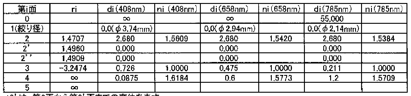
- Example 1 is an objective lens made of resin suitable for the optical pickup device shown in FIG.
- the optical surface on the light source side is the second surface (center region) including the optical axis, the second 2 ′ surface (first peripheral region) around it, and the second 2 ”surface (first
- a wavelength-selective diffractive structure has been formed that has a wavelength-selective diffraction effect that diffracts only the DVD without diffracting it on a CD.
- the depth is set to the same level, and the number of level surfaces formed in each pattern is 5, and the level is shifted by 4 steps corresponding to the number of level surfaces 5.
- phase difference of the second light flux passing through the level surface before and after the step ⁇ 1 (the phase difference obtained by subtracting an integral multiple of 2 ⁇ that is optically equiphase) is 2 ⁇ XO. Since the number of surfaces is 5, the phase difference of the second light beam is 5 ⁇ 2 ⁇ X0.198 2 ⁇ , which is equivalent to one pattern, and the first-order diffracted light is generated.
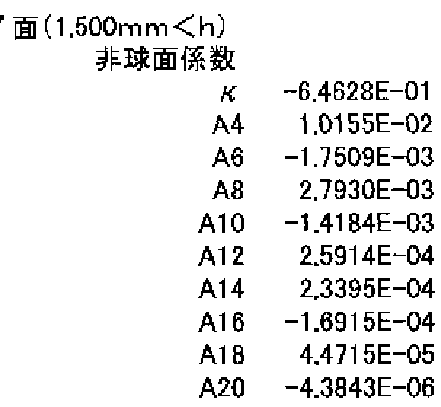
- the 2 "surface is aspherical.
- the optical surface on the optical disc side has a blur ⁇ ⁇ Diffraction structure (third diffraction structure) with a wavelength of 408 nm is formed, and its diffraction orders are BD: 10th order, DVD: 6th order, CD: 5th order, and its diffraction efficiency is BD: 100%, DVD: 100 %, CD: 100%
- the change in spherical aberration associated with a temperature change of + 30 ° C is 0.006 RMS (0.16 8 RMS when no diffractive structure is added to the third surface), and the total diffraction efficiency is BD: 86%, DVD: 89%, CD: 72%
- ST is the sum of the area of the central area, the first peripheral area, and the second peripheral area.
- the SC ratio SCZST which is the area of the central region, is 0.33.
- Table 1 shows the lens data of Example 1 (including the focal length, the image plane side numerical aperture, and the magnification).
- a power of 10 for example, 2.5X10⁻³
- E for example, 2.5E-3.
- Optical path difference function (BD: 1st order DVD: 1st order CD: 1st order Production wavelength 550nrr
- BD 10th order DVD: 6th order production wavelength 408nm
- the optical surface of the objective lens is formed as an aspherical surface that is axisymmetric about the optical axis and is defined by a mathematical formula in which the coefficients shown in Table 1 are substituted into Formula 1.
- h is the height of the optical axis force.
- optical path length given to the light flux of each wavelength by the diffractive structure is defined by an equation obtained by substituting the coefficient shown in Table 1 into the optical path difference function of equation (2).
- ⁇ is the wavelength of the incident light beam
- ⁇ ⁇ is the manufacturing wavelength (blazed wavelength)
- dor is the diffraction order
- C is the manufacturing wavelength
- Example 2 is an objective lens made of resin suitable for the optical pickup device shown in FIG.
- the optical surface on the light source side is the second surface (center region) including the optical axis, the second 2 ′ surface (first peripheral region) around it, and the second 2 ”surface (
- a wavelength-selective diffractive structure is formed that has a wavelength-selective diffraction effect that diffracts only the DVD.
- the depth is set to 1.455 / zm, which is twice the bundle, the number of level surfaces formed in each pattern is 5, and the steps are shifted by the height of 4 steps corresponding to 5 level surfaces. It is the structure made to do.
- BD and CD are not diffracted (0th order light), and DV D generates 1st order diffracted light.
- the second "surface is aspherical.
- a diffractive structure (third diffractive structure) having a blazed wavelength of 408 nm is formed on the optical surface (third surface) on the optical disk side, and its diffraction order.
- BD 10th order
- DVD 6th order
- CD 5th order
- its diffraction efficiency is BD: 100%
- DVD 100%
- CD 100%.
- the change in spherical aberration accompanying the wavelength shift of +5 nm is 0.014 RMS (0.057 RMS when the third surface is not given a diffraction structure), and the total diffraction efficiency is BD: 99%, DVD : 77%, CD: 50%
- ST is the sum of the areas of the central area, the first peripheral area, and the second peripheral area, and the area of the central area.
- the itSC / ST of the SC is 0.33.
- Table 2 shows lens data (including focal length, numerical aperture, and magnification) of Example 2.
- BD 1st order Next production wavelength 45Dnm
- the optical path difference function (BD: 0-order DVD:! "Following GD: 0-order manufacturing wavelength 653 n m C1 2.3479E-03
- Example 3 is an objective lens made of resin suitable for the optical pickup device shown in FIG.
- the optical surface on the light source side is the second surface (center region) including the optical axis, the second 2 ′ surface (first peripheral region) around it, and the second 2 ”surface
- the second "surface is aspherical.
- a diffractive structure (third diffractive structure) with a blazed wavelength of 408 nm is formed on the optical surface (third surface) on the optical disc side.
- the diffraction order is BD: 10th order, DVD: 6th order, CD: It is fifth order, and its diffraction efficiency is BD: 100%, DVD: 100%, CD: 100%.
- the defocus generation amount accompanying the wavelength shift of +0.5 nm is 0.043 MS (0.096 RMS when no diffraction structure is added to the third surface), and the total The diffraction efficiency is BD: 86%, DVD: 91%, CD: 72%.
- the ratio SC / ST of ST which is the sum of the areas of the central region, the first peripheral region, and the second peripheral region, and SC, which is the area of the central region, is 0.33. is there.
- Table 3 shows the lens data of Example 3 (including the focal length, numerical aperture, and magnification).
- NA1 0.35 NA2: 0.65 NA3: 0.46
- * 2 '' represents the displacement from the 2 'surface to the 2' surface.
- BD 1st order DVD: 1st order CD: 1st order production wavelength Onm
- BD 10th order DVD: 6th order production wavelength 408nm
- information can be recorded and Z or reproduced on three types of discs with different recording densities, including high-density optical discs having a diffractive structure and using a blue-violet laser light source, and DVD and CD.
- a group of objective lenses that can be appropriately performed, in particular, an objective lens that generates a sufficiently small amount of coma when the objective lens is tracking driven when using a CD, and an optical pickup device and an optical disk drive device using the objective lens can be provided.
Landscapes
- Physics & Mathematics (AREA)
- Optics & Photonics (AREA)
- General Physics & Mathematics (AREA)
- Optical Head (AREA)
- Lenses (AREA)
- Diffracting Gratings Or Hologram Optical Elements (AREA)
Abstract
Description


Claims
Priority Applications (4)
| Application Number | Priority Date | Filing Date | Title |
|---|---|---|---|
| CN2005800010784A CN1860535B (zh) | 2004-10-29 | 2005-10-20 | 物镜、光拾取装置及光盘驱动装置 |
| KR1020067006701A KR101165476B1 (ko) | 2004-10-29 | 2005-10-20 | 대물 렌즈, 광픽업 장치 및 광디스크 드라이브 장치 |
| EP05795842A EP1806743A4 (en) | 2004-10-29 | 2005-10-20 | LENS LENS, OPTICAL SENSOR AND OPTICAL DISK DRIVE |
| JP2006543061A JP4321589B2 (ja) | 2004-10-29 | 2005-10-20 | 対物レンズ、光ピックアップ装置及び光ディスクドライブ装置 |
Applications Claiming Priority (2)
| Application Number | Priority Date | Filing Date | Title |
|---|---|---|---|
| JP2004-316778 | 2004-10-29 | ||
| JP2004316778 | 2004-10-29 |
Publications (1)
| Publication Number | Publication Date |
|---|---|
| WO2006046465A1 true WO2006046465A1 (ja) | 2006-05-04 |
Family
ID=36227705
Family Applications (1)
| Application Number | Title | Priority Date | Filing Date |
|---|---|---|---|
| PCT/JP2005/019300 Ceased WO2006046465A1 (ja) | 2004-10-29 | 2005-10-20 | 対物レンズ、光ピックアップ装置及び光ディスクドライブ装置 |
Country Status (7)
| Country | Link |
|---|---|
| US (1) | US7623434B2 (ja) |
| EP (1) | EP1806743A4 (ja) |
| JP (1) | JP4321589B2 (ja) |
| KR (1) | KR101165476B1 (ja) |
| CN (1) | CN1860535B (ja) |
| TW (1) | TW200638397A (ja) |
| WO (1) | WO2006046465A1 (ja) |
Cited By (4)
| Publication number | Priority date | Publication date | Assignee | Title |
|---|---|---|---|---|
| JP2009009674A (ja) * | 2007-11-21 | 2009-01-15 | Konica Minolta Opto Inc | 光ピックアップ装置及び対物光学素子 |
| JP2009245575A (ja) * | 2007-07-30 | 2009-10-22 | Sony Corp | 対物レンズ、光ピックアップ及び光ディスク装置 |
| JP2010044840A (ja) * | 2008-08-18 | 2010-02-25 | Konica Minolta Opto Inc | 光ピックアップ装置用の対物光学素子及び光ピックアップ装置 |
| JP2010055732A (ja) * | 2008-07-30 | 2010-03-11 | Konica Minolta Opto Inc | 対物光学素子及び光ピックアップ装置 |
Families Citing this family (14)
| Publication number | Priority date | Publication date | Assignee | Title |
|---|---|---|---|---|
| US8116187B2 (en) * | 2004-12-01 | 2012-02-14 | Hoya Corporation | Design method of optical element and optical element through which a plurality of light beams having different design wavelengths pass |
| JP4187054B2 (ja) * | 2006-07-14 | 2008-11-26 | コニカミノルタオプト株式会社 | 光ピックアップ装置、対物光学素子及び光情報記録再生装置 |
| CN101123100B (zh) * | 2006-07-14 | 2011-05-11 | 柯尼卡美能达精密光学株式会社 | 光拾取装置、对物光学元件和光信息记录重放装置 |
| JP4165593B2 (ja) * | 2006-09-26 | 2008-10-15 | 日本電気株式会社 | 光学的情報記録媒体 |
| CN101578337A (zh) * | 2006-10-12 | 2009-11-11 | 柯尼卡美能达精密光学株式会社 | 有机无机复合材料以及光学元件 |
| WO2008069193A1 (ja) * | 2006-12-04 | 2008-06-12 | Panasonic Corporation | 光ヘッド、光情報記録再生装置および光情報システム装置 |
| US8270095B2 (en) * | 2006-12-20 | 2012-09-18 | Konica Minolta Opto, Inc. | Variable-power optical system, image pickup device, and digital apparatus |
| KR20080071380A (ko) * | 2007-01-30 | 2008-08-04 | 삼성전자주식회사 | 홀로그램 소자 및 이를 채용한 호환형 광픽업 장치 |
| JP5310386B2 (ja) * | 2009-06-18 | 2013-10-09 | ソニー株式会社 | 対物レンズ、光ピックアップ及び光ディスク装置 |
| JP2011054231A (ja) * | 2009-09-01 | 2011-03-17 | Sanyo Electric Co Ltd | 光ピックアップ装置 |
| US8873166B2 (en) * | 2010-09-29 | 2014-10-28 | Konica Minolta Advanced Layers, Inc. | Objective lens for optical pickup device, and optical pickup device |
| JP2012160224A (ja) * | 2011-01-31 | 2012-08-23 | Sanyo Electric Co Ltd | 対物レンズおよびそれを用いた光ピックアップ装置、対物レンズの製造方法 |
| CN103197403B (zh) * | 2013-04-26 | 2015-01-21 | 苏州大学 | 一种用于偏振成像仪的分孔径光学镜头 |
| EP3692349B1 (en) * | 2017-10-03 | 2021-12-01 | Philip Morris Products S.A. | Aerosol-generating device and system comprising a pyrometer |
Citations (4)
| Publication number | Priority date | Publication date | Assignee | Title |
|---|---|---|---|---|
| WO2001026103A1 (en) * | 1999-10-06 | 2001-04-12 | Sony Corporation | Objective lens and optical pickup |
| WO2003091764A1 (en) * | 2002-04-18 | 2003-11-06 | Matsushita Electric Industrial Co., Ltd. | Optical element, optical head, optical information recording/reproduction device, computer, video recording device, video reproduction device, server, and car navigation system |
| JP2004071134A (ja) * | 2002-06-10 | 2004-03-04 | Matsushita Electric Ind Co Ltd | 複合対物レンズ、光ヘッド装置、光情報装置、コンピュータ、光ディスクプレーヤー、カーナビゲーションシステム、光ディスクレコーダー、光ディスクサーバー |
| JP2004219977A (ja) * | 2002-07-31 | 2004-08-05 | Asahi Glass Co Ltd | 位相補正素子および光ヘッド装置 |
Family Cites Families (17)
| Publication number | Priority date | Publication date | Assignee | Title |
|---|---|---|---|---|
| DE60034829T2 (de) * | 1999-01-22 | 2008-01-31 | Konica Minolta Opto, Inc., Hachioji | Optische Abtastvorrichtung zur Informationsaufzeichnung und Informationswiedergabe |
| JP4060007B2 (ja) * | 1999-04-23 | 2008-03-12 | ペンタックス株式会社 | 光ディスク装置の光学系 |
| TW556178B (en) * | 2000-10-26 | 2003-10-01 | Konishiroku Photo Ind | Optical pickup apparatus and objective lens |
| US7206276B2 (en) * | 2001-10-12 | 2007-04-17 | Konica Corporation | Objective lens, optical element, optical pick-up apparatus and optical information recording and/or reproducing apparatus equipped therewith |
| JP2003322793A (ja) * | 2002-05-08 | 2003-11-14 | Pentax Corp | 光ヘッド用対物レンズ |
| JP2004327003A (ja) * | 2002-07-26 | 2004-11-18 | Sharp Corp | 光ピックアップ |
| JP2004145907A (ja) * | 2002-08-30 | 2004-05-20 | Konica Minolta Holdings Inc | 光ピックアップ装置、集光光学素子及び補正素子 |
| JP4300914B2 (ja) | 2002-12-18 | 2009-07-22 | コニカミノルタホールディングス株式会社 | 光ピックアップ装置及び光学素子 |
| US7577077B2 (en) * | 2002-09-05 | 2009-08-18 | Konica Corporation | Optical pickup apparatus and optical element |
| AU2003263605A1 (en) * | 2002-09-30 | 2004-04-23 | Konica Minolta Holdings, Inc. | Optical element, objective optical element and optical pickup device |
| TW200502670A (en) * | 2002-11-21 | 2005-01-16 | Konica Minolta Holdings Inc | Objective lens, optical system and optical pickup apparatus |
| EP1465170A3 (en) * | 2003-03-31 | 2007-05-16 | Konica Minolta Holdings, Inc. | Converging optical system of optical pickup device |
| US6982838B2 (en) * | 2003-06-04 | 2006-01-03 | Pentax Corporation | Objective lens for optical pick-up |
| US7239598B2 (en) * | 2003-06-17 | 2007-07-03 | Pentax Corporation | Objective lens for optical pick-up |
| US7038862B2 (en) * | 2003-06-17 | 2006-05-02 | Pentax Corporation | Objective lens for optical pick-up |
| JP3865738B2 (ja) | 2003-06-18 | 2007-01-10 | Tdk株式会社 | 薄膜磁気ヘッド、ヘッドジンバルアセンブリおよびハードディスク装置 |
| EP1655727A4 (en) * | 2003-08-12 | 2008-07-16 | Konica Minolta Opto Inc | OPTICAL DETECTION DEVICE |
-
2005
- 2005-10-20 WO PCT/JP2005/019300 patent/WO2006046465A1/ja not_active Ceased
- 2005-10-20 CN CN2005800010784A patent/CN1860535B/zh not_active Expired - Fee Related
- 2005-10-20 KR KR1020067006701A patent/KR101165476B1/ko not_active Expired - Fee Related
- 2005-10-20 EP EP05795842A patent/EP1806743A4/en not_active Withdrawn
- 2005-10-20 JP JP2006543061A patent/JP4321589B2/ja not_active Expired - Fee Related
- 2005-10-26 US US11/258,280 patent/US7623434B2/en not_active Expired - Fee Related
- 2005-10-27 TW TW094137692A patent/TW200638397A/zh unknown
Patent Citations (4)
| Publication number | Priority date | Publication date | Assignee | Title |
|---|---|---|---|---|
| WO2001026103A1 (en) * | 1999-10-06 | 2001-04-12 | Sony Corporation | Objective lens and optical pickup |
| WO2003091764A1 (en) * | 2002-04-18 | 2003-11-06 | Matsushita Electric Industrial Co., Ltd. | Optical element, optical head, optical information recording/reproduction device, computer, video recording device, video reproduction device, server, and car navigation system |
| JP2004071134A (ja) * | 2002-06-10 | 2004-03-04 | Matsushita Electric Ind Co Ltd | 複合対物レンズ、光ヘッド装置、光情報装置、コンピュータ、光ディスクプレーヤー、カーナビゲーションシステム、光ディスクレコーダー、光ディスクサーバー |
| JP2004219977A (ja) * | 2002-07-31 | 2004-08-05 | Asahi Glass Co Ltd | 位相補正素子および光ヘッド装置 |
Non-Patent Citations (1)
| Title |
|---|
| See also references of EP1806743A4 * |
Cited By (7)
| Publication number | Priority date | Publication date | Assignee | Title |
|---|---|---|---|---|
| JP2009245575A (ja) * | 2007-07-30 | 2009-10-22 | Sony Corp | 対物レンズ、光ピックアップ及び光ディスク装置 |
| JP2010170694A (ja) * | 2007-07-30 | 2010-08-05 | Sony Corp | 対物レンズ、光ピックアップ及び光ディスク装置 |
| US7924684B2 (en) | 2007-07-30 | 2011-04-12 | Sony Corporation | Object lens, optical pickup, and optical disc device |
| US8102749B2 (en) | 2007-07-30 | 2012-01-24 | Sony Corporation | Object lens, optical pickup, and optical disc device |
| JP2009009674A (ja) * | 2007-11-21 | 2009-01-15 | Konica Minolta Opto Inc | 光ピックアップ装置及び対物光学素子 |
| JP2010055732A (ja) * | 2008-07-30 | 2010-03-11 | Konica Minolta Opto Inc | 対物光学素子及び光ピックアップ装置 |
| JP2010044840A (ja) * | 2008-08-18 | 2010-02-25 | Konica Minolta Opto Inc | 光ピックアップ装置用の対物光学素子及び光ピックアップ装置 |
Also Published As
| Publication number | Publication date |
|---|---|
| CN1860535B (zh) | 2011-05-11 |
| EP1806743A4 (en) | 2008-12-10 |
| EP1806743A1 (en) | 2007-07-11 |
| US20060092815A1 (en) | 2006-05-04 |
| JPWO2006046465A1 (ja) | 2008-05-22 |
| TW200638397A (en) | 2006-11-01 |
| JP4321589B2 (ja) | 2009-08-26 |
| US7623434B2 (en) | 2009-11-24 |
| KR101165476B1 (ko) | 2012-07-13 |
| KR20070067001A (ko) | 2007-06-27 |
| CN1860535A (zh) | 2006-11-08 |
Similar Documents
| Publication | Publication Date | Title |
|---|---|---|
| JP4187054B2 (ja) | 光ピックアップ装置、対物光学素子及び光情報記録再生装置 | |
| JP5019273B2 (ja) | 光ピックアップ装置、対物光学素子及び光情報記録再生装置 | |
| JP4321589B2 (ja) | 対物レンズ、光ピックアップ装置及び光ディスクドライブ装置 | |
| JPWO2005117001A1 (ja) | 対物光学系、光ピックアップ装置、及び光ディスクドライブ装置 | |
| JP5003428B2 (ja) | 光ピックアップ装置及び対物光学素子 | |
| JP3957003B2 (ja) | 光ピックアップ装置及び、対物光学ユニット及び対物光学系の設計方法 | |
| JP2007179720A (ja) | 光ピックアップ装置用の対物レンズ、光ピックアップ装置用の対物レンズユニット及び光ピックアップ装置 | |
| CN101123100A (zh) | 光拾取装置、对物光学元件和光信息记录重放装置 |
Legal Events
| Date | Code | Title | Description |
|---|---|---|---|
| WWE | Wipo information: entry into national phase |
Ref document number: 200580001078.4 Country of ref document: CN |
|
| WWE | Wipo information: entry into national phase |
Ref document number: 2006543061 Country of ref document: JP |
|
| WWE | Wipo information: entry into national phase |
Ref document number: 2005795842 Country of ref document: EP |
|
| WWE | Wipo information: entry into national phase |
Ref document number: 1020067006701 Country of ref document: KR |
|
| AK | Designated states |
Kind code of ref document: A1 Designated state(s): AE AG AL AM AT AU AZ BA BB BG BW BY BZ CA CH CN CO CR CU CZ DK DM DZ EC EE EG ES FI GB GD GH GM HR HU ID IL IN IS JP KE KG KP KR KZ LC LK LR LS LT LU LV LY MD MG MK MN MW MX MZ NA NG NO NZ OM PG PH PL PT RO RU SC SD SG SK SL SM SY TJ TM TN TR TT TZ UG US UZ VC VN YU ZA ZM |
|
| AL | Designated countries for regional patents |
Kind code of ref document: A1 Designated state(s): BW GH GM KE LS MW MZ NA SD SZ TZ UG ZM ZW AM AZ BY KG MD RU TJ TM AT BE BG CH CY DE DK EE ES FI FR GB GR HU IE IS IT LU LV MC NL PL PT RO SE SI SK TR BF BJ CF CG CI CM GA GN GQ GW MR NE SN TD TG |
|
| 121 | Ep: the epo has been informed by wipo that ep was designated in this application | ||
| NENP | Non-entry into the national phase |
Ref country code: DE |
|
| WWP | Wipo information: published in national office |
Ref document number: 2005795842 Country of ref document: EP |