WO2006134944A1 - サーメット製インサート及び切削工具 - Google Patents

サーメット製インサート及び切削工具 Download PDF

Info

Publication number
WO2006134944A1
WO2006134944A1 PCT/JP2006/311873 JP2006311873W WO2006134944A1 WO 2006134944 A1 WO2006134944 A1 WO 2006134944A1 JP 2006311873 W JP2006311873 W JP 2006311873W WO 2006134944 A1 WO2006134944 A1 WO 2006134944A1
Authority
WO
WIPO (PCT)
Prior art keywords
phase
mass
cutting
hard phase
titanium carbonitride
Prior art date
Legal status (The legal status is an assumption and is not a legal conclusion. Google has not performed a legal analysis and makes no representation as to the accuracy of the status listed.)
Ceased
Application number
PCT/JP2006/311873
Other languages
English (en)
French (fr)
Inventor
Toshiyuki Taniuchi
Masafumi Fukumura
Kei Takahashi
Tomoaki Shindo
Atsushi Komura
Hiroaki Takashima
Current Assignee (The listed assignees may be inaccurate. Google has not performed a legal analysis and makes no representation or warranty as to the accuracy of the list.)
Mitsubishi Materials Corp
Niterra Co Ltd
Original Assignee
Mitsubishi Materials Corp
NGK Spark Plug Co Ltd
Priority date (The priority date is an assumption and is not a legal conclusion. Google has not performed a legal analysis and makes no representation as to the accuracy of the date listed.)
Filing date
Publication date
Priority claimed from JP2005173463A external-priority patent/JP4569767B2/ja
Priority claimed from JP2005259171A external-priority patent/JP4553382B2/ja
Priority claimed from JP2005259169A external-priority patent/JP4553380B2/ja
Priority claimed from JP2005259170A external-priority patent/JP4553381B2/ja
Priority claimed from JP2005303096A external-priority patent/JP4695960B2/ja
Application filed by Mitsubishi Materials Corp, NGK Spark Plug Co Ltd filed Critical Mitsubishi Materials Corp
Priority to EP06757308.9A priority Critical patent/EP1892052B1/en
Priority to US11/916,329 priority patent/US7762747B2/en
Publication of WO2006134944A1 publication Critical patent/WO2006134944A1/ja
Anticipated expiration legal-status Critical
Ceased legal-status Critical Current

Links

Classifications

    • CCHEMISTRY; METALLURGY
    • C22METALLURGY; FERROUS OR NON-FERROUS ALLOYS; TREATMENT OF ALLOYS OR NON-FERROUS METALS
    • C22CALLOYS
    • C22C29/00Alloys based on carbides, oxides, nitrides, borides, or silicides, e.g. cermets, or other metal compounds, e.g. oxynitrides, sulfides
    • C22C29/02Alloys based on carbides, oxides, nitrides, borides, or silicides, e.g. cermets, or other metal compounds, e.g. oxynitrides, sulfides based on carbides or carbonitrides
    • C22C29/04Alloys based on carbides, oxides, nitrides, borides, or silicides, e.g. cermets, or other metal compounds, e.g. oxynitrides, sulfides based on carbides or carbonitrides based on carbonitrides
    • BPERFORMING OPERATIONS; TRANSPORTING
    • B23MACHINE TOOLS; METAL-WORKING NOT OTHERWISE PROVIDED FOR
    • B23BTURNING; BORING
    • B23B27/00Tools for turning or boring machines; Tools of a similar kind in general; Accessories therefor
    • B23B27/14Cutting tools of which the bits or tips or cutting inserts are of special material
    • CCHEMISTRY; METALLURGY
    • C22METALLURGY; FERROUS OR NON-FERROUS ALLOYS; TREATMENT OF ALLOYS OR NON-FERROUS METALS
    • C22CALLOYS
    • C22C27/00Alloys based on rhenium or a refractory metal not mentioned in groups C22C14/00 or C22C16/00
    • C22C27/04Alloys based on tungsten or molybdenum
    • CCHEMISTRY; METALLURGY
    • C22METALLURGY; FERROUS OR NON-FERROUS ALLOYS; TREATMENT OF ALLOYS OR NON-FERROUS METALS
    • C22CALLOYS
    • C22C29/00Alloys based on carbides, oxides, nitrides, borides, or silicides, e.g. cermets, or other metal compounds, e.g. oxynitrides, sulfides
    • C22C29/02Alloys based on carbides, oxides, nitrides, borides, or silicides, e.g. cermets, or other metal compounds, e.g. oxynitrides, sulfides based on carbides or carbonitrides
    • BPERFORMING OPERATIONS; TRANSPORTING
    • B22CASTING; POWDER METALLURGY
    • B22FWORKING METALLIC POWDER; MANUFACTURE OF ARTICLES FROM METALLIC POWDER; MAKING METALLIC POWDER; APPARATUS OR DEVICES SPECIALLY ADAPTED FOR METALLIC POWDER
    • B22F5/00Manufacture of workpieces or articles from metallic powder characterised by the special shape of the product
    • B22F2005/001Cutting tools, earth boring or grinding tool other than table ware
    • BPERFORMING OPERATIONS; TRANSPORTING
    • B22CASTING; POWDER METALLURGY
    • B22FWORKING METALLIC POWDER; MANUFACTURE OF ARTICLES FROM METALLIC POWDER; MAKING METALLIC POWDER; APPARATUS OR DEVICES SPECIALLY ADAPTED FOR METALLIC POWDER
    • B22F2998/00Supplementary information concerning processes or compositions relating to powder metallurgy
    • B22F2998/10Processes characterised by the sequence of their steps
    • BPERFORMING OPERATIONS; TRANSPORTING
    • B22CASTING; POWDER METALLURGY
    • B22FWORKING METALLIC POWDER; MANUFACTURE OF ARTICLES FROM METALLIC POWDER; MAKING METALLIC POWDER; APPARATUS OR DEVICES SPECIALLY ADAPTED FOR METALLIC POWDER
    • B22F2999/00Aspects linked to processes or compositions used in powder metallurgy
    • YGENERAL TAGGING OF NEW TECHNOLOGICAL DEVELOPMENTS; GENERAL TAGGING OF CROSS-SECTIONAL TECHNOLOGIES SPANNING OVER SEVERAL SECTIONS OF THE IPC; TECHNICAL SUBJECTS COVERED BY FORMER USPC CROSS-REFERENCE ART COLLECTIONS [XRACs] AND DIGESTS
    • Y10TECHNICAL SUBJECTS COVERED BY FORMER USPC
    • Y10TTECHNICAL SUBJECTS COVERED BY FORMER US CLASSIFICATION
    • Y10T407/00Cutters, for shaping
    • Y10T407/19Rotary cutting tool
    • Y10T407/1906Rotary cutting tool including holder [i.e., head] having seat for inserted tool
    • Y10T407/1908Face or end mill
    • Y10T407/1924Specified tool shape
    • YGENERAL TAGGING OF NEW TECHNOLOGICAL DEVELOPMENTS; GENERAL TAGGING OF CROSS-SECTIONAL TECHNOLOGIES SPANNING OVER SEVERAL SECTIONS OF THE IPC; TECHNICAL SUBJECTS COVERED BY FORMER USPC CROSS-REFERENCE ART COLLECTIONS [XRACs] AND DIGESTS
    • Y10TECHNICAL SUBJECTS COVERED BY FORMER USPC
    • Y10TTECHNICAL SUBJECTS COVERED BY FORMER US CLASSIFICATION
    • Y10T407/00Cutters, for shaping
    • Y10T407/22Cutters, for shaping including holder having seat for inserted tool
    • YGENERAL TAGGING OF NEW TECHNOLOGICAL DEVELOPMENTS; GENERAL TAGGING OF CROSS-SECTIONAL TECHNOLOGIES SPANNING OVER SEVERAL SECTIONS OF THE IPC; TECHNICAL SUBJECTS COVERED BY FORMER USPC CROSS-REFERENCE ART COLLECTIONS [XRACs] AND DIGESTS
    • Y10TECHNICAL SUBJECTS COVERED BY FORMER USPC
    • Y10TTECHNICAL SUBJECTS COVERED BY FORMER US CLASSIFICATION
    • Y10T407/00Cutters, for shaping
    • Y10T407/27Cutters, for shaping comprising tool of specific chemical composition

Definitions

  • the present invention relates to a cermet insert and a cutting tool.
  • the bonded phase of titanium carbonitride-based cermet (hereinafter referred to as TiCN-based cermet) has excellent high-temperature hardness, and as a result, excellent wear resistance in high-speed cutting with high heat generation
  • TiCN-based cermet titanium carbonitride-based cermet
  • the present invention relates to a TiCN-based cermet insert that exhibits fracture resistance and a cutting tool equipped with this cermet insert.
  • an insert composed of TiCN-based cermet (hereinafter simply referred to as a cutting insert) is known as one type of cutting used for turning.
  • Tungsten carbide (hereinafter referred to as WC): 20-30%
  • TaC tantalum carbide
  • NbC niobium carbide
  • Titanium carbonitride (hereinafter referred to as TiCN): It is composed of a TiCN-based cermet that is a sintered compact of a green compact having a composition containing 50-60%.
  • Bond phase Remaining force.
  • the area ratio is a value measured by tissue observation with a scanning electron microscope.
  • the hard phase includes the following (1) to (3), as shown in FIG.
  • Ti and W in the periphery, Ta and Nb, or both composite carbonitrides [Hereinafter (Ti, W, TaZNb) CN] phase
  • Ti, W, TaZNb composite carbonitrides
  • the above-mentioned binder phase is a ratio to the binder phase and is in mass%.
  • TaZNb Ti and one or two of Ta and Nb (hereinafter referred to as TaZNb), the total amount: 5% or less, and
  • Co—Ni alloy power having a composition in which the balance is made of Co is also obtained.
  • ZrC zirconium carbide
  • VC vanadium carbide
  • Mo C molybdenum carbide
  • the following is known as a cutting insert including / VC / Mo C).
  • TaC / NbC 5-10%
  • TiCN It is composed of TiCN-based cermet, which is a sintered compact of green compact with a composition containing 50-60%. [0005] (b) The TiCN-based cermet is
  • Bond phase Remaining force.
  • the area ratio is a value measured by tissue observation with a scanning electron microscope.
  • the hard phase includes the following (1) to (3), as shown in FIG. 3 in which the structure observation result (magnification: 10,000 times) is shown by a scanning electron microscope.
  • the above-mentioned binder phase is a ratio to the binder phase and is in mass%.
  • TaZNb Ta and Nb
  • ZrZvZMo ZrZvZMo
  • Co—Ni alloy power having a composition in which the balance is made of Co is also obtained.
  • the above-described cutting insert is manufactured by sintering the above-mentioned blended yarn and compact green compact under the conditions of the following sintering conditions (i) to (iii): It is well known that it is used for continuous cutting and intermittent cutting of steel and pig iron.
  • the temperature is raised from 1400 to 1450 ° C. to the sintering temperature of 1480 to 1560 ° C. at a rate of 1 to 3 ° C. Zmin., and then held at the sintering temperature for 0.5 to 2 hours.
  • This temperature rise and temperature maintenance is performed in a nitrogen atmosphere of 50 to 4000 kPa.
  • cermet insert having a powerful structure with a hard phase (hard particles) and a binder phase existing between the hard phases is used for cutting steel or the like.
  • Various techniques have been proposed for improvement.
  • Patent Document 2 has an ordinary cored structure.
  • the core is rich in Group 4a elements such as Ti
  • the periphery is composed of Group 5a elements such as W and Ta, Group 6a elements. It consists of multiple phases (black phase) rich in phase and phases rich in 5a and 6a group elements such as W and Ta (white phase), and the black and white phases are dispersed at the optimum ratio TiCN cermet with improved alloy strength has been proposed.
  • Patent Document 1 Japanese Patent Laid-Open No. 10-110234
  • Patent Document 2 JP-A 62-170452
  • the present invention has been made in view of the above points.
  • a titanium carbonitride base having excellent wear resistance in high-speed cutting processing.
  • the purpose is to provide cermet inserts.
  • a second object of the present invention is to provide a cermet insert and a cutting tool that can maintain high wear resistance and can realize high fracture resistance in order to solve the problem related to Patent Document 2 described above. .
  • Patent Document 1 From the viewpoint of the above-mentioned Patent Document 1, the present inventors should first improve the wear resistance of the conventional cutting insert described in Patent Document 1 in high-speed cutting.
  • the research focused on the binder phase consisting of Co—Ni-based alloys of TiCN-based cermets. As a result, the following research results (A) to (C) were obtained.
  • the alternating atmosphere treatment is preferably a short-time Ar atmosphere holding for 1 to 5 minutes in an Ar atmosphere of 10 to 60 kPa, and a short-time vacuum atmosphere holding for 5 to 20 minutes in a vacuum atmosphere of less than lOPa. Repeat two or more times, preferably 3-5 times each.
  • the titanium carbonitride-based cermet insert of the present invention has been made based on the above research results.
  • the first aspect of the titanium carbonitride-based cermet insert of the present invention is:
  • Hard phase 75-90 area% and The remainder has a titanium carbonitride-based cermet having a structure that also has a binding affinity.
  • the hard phase has the following first to third hard phases.
  • Composite carbonitride (hereinafter referred to as (Ti, W, TaZNb)) that has a core part of titanium carbonitride and a peripheral part of Ti, W, and one or two of Ta and Nb
  • the first hard phase with a core structure consisting of a phase (denoted CN).
  • Titanium carbonitride phase The third hard phase with a single-phase structure.
  • the binder phase is a proportion of the binder phase and is at least by mass%.
  • W W—Co—Ni-based alloy having a composition containing 40 to 60%.
  • the first embodiment of the titanium carbonitride-based cermet insert of the present invention exhibits excellent wear resistance in high-speed cutting with high heat generation.
  • the titanium carbonitride-based cermet insert of the present invention is
  • Tungsten carbide 20-30%
  • One or two of tantalum carbide and niobium carbide 5-10%
  • Titanium carbonitride It may be a sintered body of a green compact having a composition containing 50-60%.
  • the remainder has a titanium carbonitride-based cermet having a structure that also has a binding affinity.
  • the hard phase has the following first to third hard phases.
  • Titanium carbonitride is compatible with the core, and the periphery is Ti, W, one or two of Ta and Nb, and one or more of Zr, V, and Mo
  • Titanium carbonitride phase The third hard phase with a single-phase structure.
  • the binder phase is a proportion of the binder phase and is at least by mass%.
  • W W—Co—Ni-based alloy having a composition containing 40 to 60%.
  • the second aspect of the titanium carbonitride-based cermet insert of the present invention exhibits excellent wear resistance in high-speed cutting with high heat generation.
  • the titanium carbonitride-based cermet insert of the present invention is
  • Tungsten carbide 20-30%
  • One or two of tantalum carbide and niobium carbide 5-10%
  • zirconium carbide, vanadium carbide, and molybdenum carbide 1-5%
  • Titanium carbonitride It may be a sintered body of a green compact having a composition containing 50-60%.
  • a third embodiment of the cermet insert of the present invention is a titanium carbonitride cermet containing Ti, one or two of Ta and Nb, and W having a sintered strength.
  • the sum of the value of Ti converted to carbonitride, the value of one or two of Ta and Nb converted to carbide, and the value of W converted to carbide constitutes the sintered body. 70 to 95% by mass with respect to the entire structure, and the value of W converted to carbide is 20 to 35% by mass with respect to the entire structure. Co and Ni are ratios with respect to the entire structure. And 5 to 30% by mass.
  • a composite carbonitride hereinafter referred to as (T i, W, TaZNb) CN
  • W contained in the whole structure 40 to 65% by mass is contained in the hard phase, and the remainder is contained in the binder phase.
  • the hard phase may further contain titanium carbonitride.
  • Ti converted to carbonitride is a ratio of 45 to 60% by mass with respect to the entire structure, and the value of one or two of Ta and Nb converted to carbide is It may be 5 to 10% by mass with respect to the entire tissue.
  • the first hard phase with a core structure consisting of a titanium carbonitride phase in the core and (Ti, W, TaZNb) CN phase in the periphery, and
  • Both the core part and the peripheral part may have one or two of the second hard phases having a core structure composed of (Ti, W, TaZNb) CN phase.
  • the hard phase is further
  • It may have a third hard phase having a single-phase structure composed of a titanium carbonitride phase.
  • the hard phase is selected from the above-described three hard phases, thereby increasing the hardness of the insert and improving the wear resistance. Can be made.
  • Mo may be contained in one or both of the hard phase and the binder phase.
  • Mo is contained in the periphery of the first hard phase, the second hard phase, and the binder phase. Note that Mo is, for example, 1 in terms of carbide (Mo C) with respect to the entire insert.
  • the content is preferably 2 to 5% by mass.
  • the binder phase may contain 40 to 60% by mass of W as a proportion of the binder phase.
  • the binder phase contains 40 to 60% by mass of W
  • the high temperature hardness of the binder phase is improved. Thereby, for example, excellent wear resistance can be exhibited in high-speed cutting with high temperature generation.
  • a cutting tool of the present invention includes a holder and the insert made of the same size of the present invention held and fixed to the holder.
  • the cutting tool of the present invention includes the cermet insert described above in the holder, excellent wear resistance and fracture resistance can be realized.
  • the binder phase of the TiCN-based cermet constituting the cutting insert is heated during sintering. Contains 40-60% W by the alternating atmosphere treatment in the process. As a result, the high-temperature hardness of the binder phase is drastically improved, so that it exhibits excellent wear resistance in high-speed cutting with high heat generation.
  • the total amount of Ti, Ta / Nb, and W is specified, so that the ratio of the hard phase and the binder phase is optimized, and excellent wear resistance and Fracture resistance is obtained. Furthermore, since 40 to 65 mass% of W is contained in the hard phase and the balance is contained in the binder phase, both high wear resistance and fracture resistance can be realized.
  • the cutting tool of the present invention includes the cermet insert described above in the holder, excellent wear resistance and fracture resistance can be realized.
  • FIG. 1 is a perspective view showing an example of a cermet insert according to the first and second embodiments. is there.
  • FIG. 2 is a copy diagram showing a structure observation result (magnification: 10,000 times) of the TiCN-based cermet constituting the cutting insert according to the first embodiment by a scanning electron microscope.
  • FIG. 3 is a copying diagram showing a structure observation result (magnification: 10,000 times) of the TiCN-based cermet constituting the cutting insert according to the second embodiment by a scanning electron microscope.
  • FIG. 4A is an explanatory view schematically showing a cross section of a cermet insert according to a third embodiment.
  • FIG. 4B is an explanatory diagram schematically showing the first hard phase, the second hard phase, and the third hard phase that constitute the hard phase.
  • FIG. 5 is a perspective view showing a cermet insert according to a third embodiment.
  • FIG. 6 is an explanatory view showing a cutting tool according to a third embodiment.
  • FIG. 7 is an explanatory view showing a method for producing a cermet insert according to an embodiment. Explanation of symbols
  • the titanium carbonitride-based cermet insert (hereinafter also referred to as a cutting insert) of this embodiment is formed from a titanium carbonitride-based cermet.
  • the cutting insert for example, the insert 11 having a chip shape of ISO standard CNMG 120412 shown in FIG.
  • This titanium carbonitride-based cermet is, by weight, at least tungsten carbide: 20-30%, one or two of tantalum carbide and niobium carbide (hereinafter also referred to as TaCZNbC): 5-10%, Co: It is a sintered compact of a green compact having a blend composition including 5 to 10%, Ni: 5 to 10%, and titanium carbonitride: 50 to 60%.
  • the structure When the structure is observed with a scanning electron microscope, it is found that the structure has a hard phase: 75 to 90 area% and a binder phase: the remainder.
  • the hard phase includes the following (1) to (3) as shown in the copying diagram of FIG. (1)
  • Composite carbonitride hereinafter referred to as (Ti, W, TaZNb)
  • Ti, W, TaZNb Composite carbonitride
  • Ti, W, TaZNb Composite carbonitride
  • Titanium carbonitride phase The third hard phase with a single-phase structure.
  • the binder phase is a proportion of the binder phase and is in mass%.
  • a W—Co—Ni-based alloy having a composition containing at least one of Ti and one or two of Ta and Nb, the total amount of which is 5% or less, and W: 40-60%.
  • compositional composition of the TiCN-based cermet constituting the cutting insert and the component composition of the binder phase are numerically limited as described above will be described below.
  • the raw material powder, WC powder dissolves in the Co and Ni components that form the binder phase during sintering, and remains in the binder phase as a result of the alternating atmosphere treatment described above, forming a high W-containing binder phase. To do. As a result, the high-temperature hardness of the binder phase is improved, so that W contributes to the improvement of wear resistance in high-speed cutting of the cutting insert. If the blending ratio of WC is less than 20%, the W content in the binder phase will be less than 40% in the binder phase. As a result, the desired wear resistance cannot be exhibited in high-speed cutting with high heat generation.
  • the proportion of WC exceeds 30%, the W component content in the binder phase will increase to over 60% in the binder phase. As a result, the high-temperature strength of the binder phase itself sharply decreases, and this makes it easier for chipping (small chipping) to occur during cutting. From the above points, the proportion of WC is set to 20 to 30%, and the TiCN-based cermet binder phase is determined to contain 40 to 60% of the W component by the atmosphere change process.
  • TaC powder and NbC powder which are raw material powders, also form binder phase components during sintering. It dissolves in certain Co and Ni components and precipitates upon cooling to form a hard phase.
  • Ta and Nb are contained as a solid solution in the periphery and part of the core of the hard phase, and have the effect of improving the high-temperature strength of the hard phase.
  • the blending ratio of one or two of TaC powder and NbC powder is less than 5%, a desired improvement effect cannot be obtained in the above action.
  • the blending ratio exceeds 10%, the content ratio in the hard phase becomes too high.
  • the content ratio in the binder phase by force will increase by more than 5% in terms of the total amount of Ti in the binder phase.
  • the high temperature hardness suddenly decreases.
  • the blending ratio of one or two of TaC and NbC is 5 to 10%, and the total amount of Ti in the binder phase and one or two of Ta and Nb It is determined to be 5% or less as a percentage of the binder phase.
  • Co has the effect of improving the sinterability, forming a binder phase, and improving the strength of the cutting insert.
  • the blending ratio is less than 5%, the desired sinterability cannot be ensured, and the Co content ratio (ratio in the binder phase) in the binder phase is less than 18%.
  • the desired strength improvement effect cannot be ensured for the cutting insert.
  • the compounding ratio exceeds 10%, the Co content ratio in the binder phase after sintering becomes higher than 33%. As a result, the high-temperature hardness of the binder phase decreases, and wear proceeds rapidly.
  • the Co content is determined to be 5 to 10% and the Co content in the binder phase is 18 to 33%.
  • Ni has the effect of forming a binder phase with Co during sintering, improving the heat resistance of the binder phase, and contributing to the improved wear resistance of the cutting insert.
  • the blending ratio is less than 5%, the content ratio of Ni component in the binder phase after sintering (ratio in the binder phase) is less than 20%, and the desired heat resistance improvement effect cannot be obtained.
  • the blending ratio exceeds 10%, the Ni content in the binder phase after sintering becomes higher than 35%. As a result, the high-temperature strength of the binder phase decreases, and chipping tends to occur at the cutting edge. From the above points, the Ni content is determined to be 5-10% and the Ni content in the binder phase is 20-35%.
  • the TiCN powder which is the raw material powder, forms the hard phase having the first to third hard phases described above during sintering, thereby improving the hardness of the cutting insert and contributing to improved wear resistance.
  • the proportion of TiCN is less than 50%, the proportion of the hard phase in the cutting insert is less than 75 area%, and the desired hardness cannot be ensured.
  • the proportion of TiCN is more than 60%, the proportion of the hard phase is higher than 90% by area. As a result, the strength of the cutting insert is sharply reduced, and chipping is likely to occur during cutting.
  • the ratio of Ti in the binder phase to one or two of Ta and Nb in the total mass-bonded phase becomes higher than 5%. As a result, the high-temperature hardness of the binder phase is reduced, which causes accelerated wear during high-speed cutting. From the above points, the composition ratio of TiCN is 50-60%, and the total amount of Ti in the binder phase and one or two of Ta and Nb is 5% or less as a percentage of the binder phase. It is determined as follows.
  • the titanium carbonitride-based cermet insert (hereinafter also referred to as a cutting insert) of the present embodiment is at least 1% or 2 types of tungsten carbide: 20 to 30%, tantalum carbide and carbonized carbide (hereinafter also referred to as cutting insert) ( (Hereinafter also referred to as TaCZNbC): 5 to 10%, one or two of zirconium carbide, vanadium carbide, and molybdenum carbide (hereinafter also referred to as ZrCZVC / Mo C): 1 to 5%, Co: 5-10%, Ni: 5-10%, and titanium carbonitride: 50
  • the structure When the structure is observed with a scanning electron microscope, it is found that the structure has a hard phase: 75 to 93 area% and a binder phase: the remainder.
  • the hard phase includes the following (1) to (3) as shown in the copying diagram of FIG.
  • Titanium carbonitride is compatible with the core, and the periphery is Ti, W, one or two of Ta and Nb, and one or more of Zr, V, and Mo
  • Titanium carbonitride phase The third hard phase with a single-phase structure.
  • the binder phase is a proportion of the binder phase and, in mass%,
  • Ti one or two of Ta and Nb, and one or more of Zr, V, and Mo, including the total amount: 5% or less, and
  • W W—Co—Ni-based alloy having a composition containing at least 40 to 60%.
  • the WC powder which is a raw material powder, dissolves in the Co and Ni components that are the binder phase forming components during sintering, and is retained in the binder phase by the above-described atmosphere alternation process. Form.
  • the high-temperature hardness of the binder phase is improved, so that W contributes to improving the wear resistance of the cutting insert during high-speed cutting.
  • the W content in the binder phase will be less than 40% in the binder phase.
  • the desired wear resistance cannot be exhibited in high-speed cutting with high heat generation.
  • the proportion of WC exceeds 30%, the proportion of W component in the binder phase will increase to over 60% in the binder phase.
  • the blending ratio of WC is set to 20 to 30%, and it is determined that 40 to 60% of W component is contained in the TiCN-based cermet binder phase by the above-mentioned atmosphere change treatment.
  • TaCZNbC powder (hereinafter referred to as the former) and ZrCZVCZM o C powder (hereinafter referred to as the latter), both of which are raw material powders, are Co components that are the binder phase forming components during sintering. It dissolves in the Ni component and precipitates upon cooling to form a hard phase.
  • the solid phase is contained in the periphery and part of the core of the hard phase, the former has the action of improving the high-temperature strength of the hard phase, and the latter has the action of improving the wettability with the binder phase. For this reason, both have the effect of improving the strength of the cermet itself.
  • the blending ratio of the former is less than 5%, or the blending ratio of the latter is less than 1%, the desired improvement effect cannot be obtained in the above action.
  • the former proportion exceeds 10%, or the latter proportion exceeds 5%, the content in the hard phase becomes too high. If this causes a decrease in the hardness of the hard phase, the total amount of Ti, TaZNb, and ZrZvZMo in the binder phase will be higher than 5% in the binder phase. As a result, the high-temperature hardness suddenly decreases.
  • the mixing ratio is 5-10% in the former and 1-5% in the latter, and the total amount of Ti, TaZNb, and ZrZvZMo in the binder phase is less than 5% in the binder phase. It was decided to become.
  • Co powder which is a raw material powder, has the effect of improving the sinterability, forming a binder phase, and improving the strength of the cutting insert.
  • the blending ratio is less than 5%, not only the desired sinterability cannot be secured, but also the Co content ratio (ratio in the binder phase) in the binder phase is less than 18%. The desired strength cannot be ensured for the cutting insert.
  • the compounding ratio exceeds 10%, the Co content ratio in the binder phase after sintering becomes higher than 33%. As a result, the high-temperature hardness of the binder phase decreases, and wear proceeds rapidly. From the above points, the Co content is determined to be 5 to 10% and the Co content in the binder phase is 18 to 33%.
  • Ni which is a raw material powder, has the effect of forming a binder phase with Co during sintering and improving the heat resistance of the binder phase, thereby contributing to improved wear resistance of the cutting insert.
  • the blending ratio is less than 5%, the Ni component content ratio (ratio in the binder phase) in the binder phase after sintering is less than 20%, and the desired heat resistance improvement effect cannot be obtained.
  • the blending ratio exceeds 10%, the Ni content in the binder phase after sintering becomes higher than 35%. As a result, the high-temperature strength of the binder phase decreases and chipping occurs at the cutting edge. It becomes easy to do.
  • the Ni content is determined to be 5 to 10%, and the Ni content in the binder phase is 20 to 35%.
  • the TiCN powder which is the raw material powder, forms the hard phase having the first to third hard phases described above during sintering, thereby improving the hardness of the cutting insert and contributing to improved wear resistance.
  • the proportion of TiCN is less than 50%, the proportion of the hard phase in the cutting insert is less than 75 area%, and the desired hardness cannot be ensured.
  • the proportion of TiC N exceeds 60%, the proportion of the hard phase becomes higher than 93 area%.
  • the strength of the cutting insert is sharply reduced, and chipping is likely to occur during cutting.
  • the total amount of Ti, TaZNb, and ZrZvZMo in the binder phase becomes higher than 5% in proportion to the binder phase.
  • the proportion of TiCN is set to 50-60%, and the total amount of Ti, TaZNb, and ZrZvZMo in the binder phase is determined to be 5% or less in the binder phase.
  • the cermet insert 1 of the present embodiment is a cutting insert having a sintered body force having a shape of ISO standard: SNGN 120408 as shown in FIG.
  • This insert 1 is made of a titanium carbonitride cermet having a sintered body strength containing Ti, one or two of Ta and Nb (hereinafter also referred to as TaZNb), and W.
  • the sum of the value of Ti converted to carbonitride, the value of one or two of Ta and Nb converted to carbide, and the value of W converted to carbide is the ratio to the entire structure of the sintered body. 70 to 95% by mass.
  • carbonized_material is 20-35 mass% in the ratio with respect to the whole structure
  • Ti is contained in an amount of 45-60 mass% in terms of carbonitride with respect to the entire structure.
  • One or two of Ta and Nb are contained in 5 to 10% by mass in terms of carbide.
  • the insert 1 is composed of a structure (including inevitable impurities) composed of a hard phase (hard particles) and a binder phase existing so as to cover the periphery thereof.
  • the hard phase is composed of a composite carbonitride (hereinafter referred to as (Ti, W, TaZNb) CN) having Ti, W, and one or two of Ta and Nb, and titanium carbonitride.
  • the binder phase is mainly composed of W and one or two of Co and Ni (hereinafter also referred to as CoZNi). “The main component is W and one or two of Co and Ni” means that the total amount is larger than the total amount of other components. For example, the total amount is 98% by mass. Reach the degree.
  • the hard phase for example, all the hard phases (1) to (3) shown in Fig. 4B are provided.
  • the first hard phase with a core structure consisting of a titanium carbonitride phase in the core and a (Ti, W, TaZNb) CN phase in the periphery,
  • a third hard phase having a single-phase structure composed of a titanium carbonitride phase.
  • the Ti content is the value converted as TiCN
  • the Nb and Z or Ta content is the value converted as (Nb / Ta) C
  • the W content is the value converted as WC. .
  • Carbonitrides such as composite carbonitrides and titanium carbonitrides that form a hard phase (hard particles) have the effect of improving the hardness of the cermet and improving the wear resistance.
  • the proportion of the hard phase exceeds 95% by mass of the entire cermet
  • the proportion of the binder phase is relatively less than 5% by mass
  • the toughness is lowered and the fracture resistance is lowered.
  • the ratio of the hard phase is less than 70% by mass
  • the ratio of the binder phase relatively exceeds 30% by mass, and the cermet wear resistance is increased. Decreases.
  • the sum of the value of Ti converted to carbonitride, the value of one or two of Ta and Nb converted to carbide, and the value of W converted to carbide is the sum of the sintered body. It is determined to be 70 to 95% by mass with respect to the total composition.
  • the W for the entire organization (in WC equivalent) by including 20 to 35 mass 0/0, it is possible to improve the wear resistance of the insert Ichito.
  • Co has the effect of improving the sinterability, forming a binder phase, and improving the strength of the insert.
  • Ni has the effect of forming a binder phase during sintering and improving the heat resistance of the binder phase, thereby increasing the wear resistance of the insert.
  • W included in the entire structure is a value obtained by converting W to carbide, and 40 to 65% by mass is distributed in the hard phase, and the remainder is distributed to the binder phase.
  • the hard phase is strengthened by containing 40 to 65 mass% of W contained in the entire structure in the hard phase, so that the hard phase is strengthened. ) Is improved.
  • the wear resistance is improved. As a result, both the wear resistance and the fracture resistance can be realized.
  • the insert 1 described above is fixed to the front end of a columnar holder 3 made of steel, for example, by a fixing jig 5 as illustrated in FIG. Then, steel or the like is cut using a cutting tool 7 in which the insert 1 is fixed to the holder 3.
  • tungsten carbide 20 to 30 weight 0/0
  • titanium carbonitride a sintered compact of a green compact having a blending composition including 50-60 mass%.
  • the sintered body "a structure having a structure composed of a hard phase: 75 to 90% by area and a binder phase: the remainder in a structure observation with a scanning electron microscope” can be adopted.
  • the binder phase “in the proportion of the binder phase, at least Co: 18 to 33 mass%,? ⁇ : 20 to 35 mass%, including Ti, Ta, and Nb, or one or two of them.
  • the total amount: W—Co—Ni alloy having a composition including 5% by mass or less and W: 40 to 60% by mass ” can be employed.
  • composition usually contains inevitable impurities.
  • a and Z or B means at least one of A and B.
  • Ti As raw material powder, Ti, TiC N powder with an average particle diameter of 0.5-2 ⁇ m, Ti
  • Powder, WC powder, Co powder, and Ni powder were prepared. These raw material powders were blended in the blending composition shown in Table 1, wet-mixed for 24 hours with a ball mill, and dried. After that, the green compact was press-molded into a green compact at a pressure of 98 MPa, and this green compact was sintered / sintered under the following sintering conditions (a) to (e).
  • the temperature was raised from 1420 ° C. to a predetermined sintering temperature in the range of 1480 to 1560 ° C. at a rate of 2 ° C. Zmin., and then held at the sintering temperature for 1.5 hours.
  • the temperature was raised to the sintering temperature and held at the sintering temperature in a 1300 Pa nitrogen atmosphere.
  • Furnace cooling from the sintering temperature was performed in a vacuum atmosphere of lOPa or less.
  • FIG. 1 After sintering, the cutting edge part is shown in Fig. 1 by applying a horn carriage of R: 0.07mm.
  • the conventional cutting insert 1 was performed under substantially the same conditions except that the above-described atmosphere alternation process was not performed in the process of raising the temperature to the sintering temperature. — 1 to 1— 10 were produced respectively.
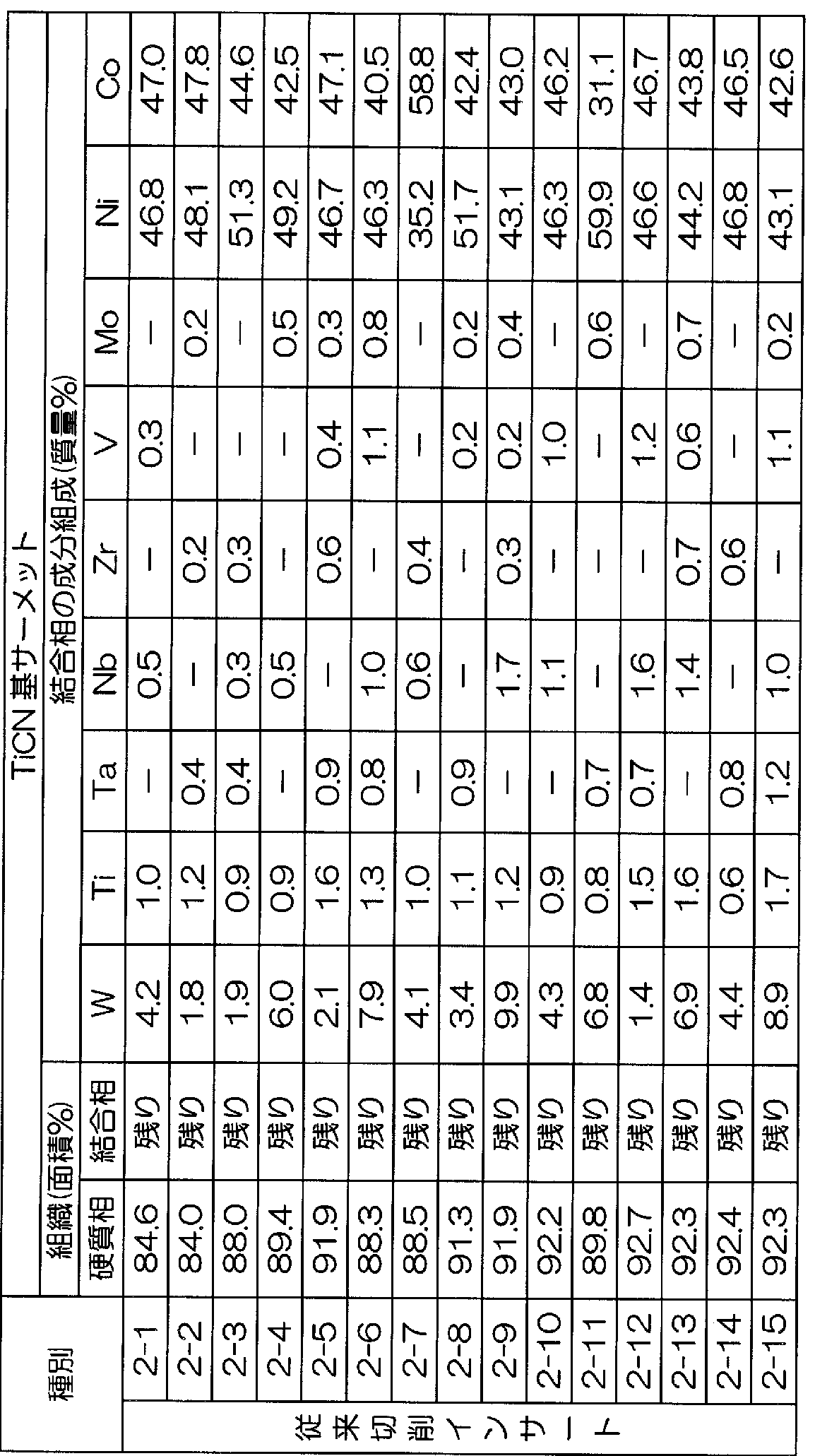
  • Tables 3 and 4 show the results of the observation of the structure of the TiCN-based cermet constituting this by a scanning electron microscope and the analysis result of the bonded phase, respectively.
  • Cutting Condition 1 A (Dry Intermittent High Speed Cutting Test for Alloy Steel)
  • Cutting condition 1 B dry continuous high-speed cutting test of carbon steel
  • Cutting time 20 minutes (normal cutting speed is 250mZmin).
  • Cutting condition 1 C dry continuous high-speed cutting test of pig iron
  • Cutting time 20 minutes (normal cutting speed is 280mZmin).
  • the cutting inserts 1-1 to 1-10 of the present invention all have a ratio of 40 to 60 in the binding phase W of the TiCN-based cermet constituting the cutting insert. It has been found that by containing it at a high content rate of 5%, it has excellent high-temperature hardness, thereby exhibiting excellent wear resistance even in high-speed cutting with high heat generation.
  • the W content in the binder phase is as low as 1 to 10% in the binder phase.
  • excellent high temperature hardness cannot be expected for the binder phase. For this reason, the progress of wear of the binder phase is accelerated particularly in high-speed cutting, and it is clear that this leads to a service life in a relatively short time.
  • the cutting insert of the present invention has excellent wear resistance not only for cutting under normal conditions such as various types of steel and pig iron, but also for high-speed cutting with high heat generation. Is issued. For this reason, it is possible to fully satisfy the labor-saving and energy-saving of cutting work and the cost reduction.
  • Ti As raw material powder, Ti, TiC N powder with an average particle diameter of 0.5-2 ⁇ m, Ti
  • NbC powder, ZrC powder, VC powder, Mo C powder, Co powder, and Ni powder are available. It was. These raw material powders were blended into the blending composition shown in Table 6, wet-mixed with a ball mill for 24 hours, and dried. Thereafter, the green compact was press-molded at a pressure of 98 MPa, and the green compact was sintered under the following sintering conditions (a) to (e).
  • the temperature was raised from 1420 ° C. to a predetermined sintering temperature in the range of 1480 to 1560 ° C. at a rate of 2 ° C. Zmin., and then held at the sintering temperature for 1.5 hours.
  • the temperature was raised to the sintering temperature and held at the sintering temperature in a 1300 Pa nitrogen atmosphere.
  • Furnace cooling from the sintering temperature was performed in a vacuum atmosphere of lOPa or less.
  • the TiCN powder which is the raw material powder, uses only the TiCN powder described above, and the atmosphere described above in the process of raising the temperature to the sintering temperature.
  • Cutting condition 2 A (carbon steel dry intermittent cutting test)
  • Cutting time 10 minutes (normal cutting speed is 250mZmin).
  • Cutting condition 2 B (Dry continuous high-speed cutting test of alloy steel)
  • Cutting time 20 minutes (normal cutting speed is 200mZmin).
  • Cutting condition 2 C (dry continuous high-speed cutting test of pig iron)
  • Cutting time 20 minutes (normal cutting speed is 280m / min).
  • the binding phase force W of the TiCN-based cermet constituting the cutting inserts 2-1 to 2-15 is 40 to 60 in the ratio of the binding phase It has been found that by containing it at a high ratio of%, it has excellent high-temperature hardness, and thus exhibits excellent wear resistance even in high-speed cutting with high heat generation.
  • the W content in the binder phase is as low as 1 to 10% in the binder phase. As a result, excellent high temperature hardness cannot be expected for the binder phase. For this reason, the progress of wear of the binder phase is accelerated particularly in high-speed cutting, and it is clear that this leads to a service life in a relatively short time.
  • the cutting insert of the present invention has excellent wear resistance not only for cutting under normal conditions such as various types of steel and pig iron, but also for high-speed cutting with high heat generation. Is issued. For this reason, it is possible to fully satisfy the labor-saving and energy-saving of cutting work and the cost reduction.
  • Example 3 A cermet insert (hereinafter simply referred to as an insert) and a cutting tool according to the third embodiment will be specifically described by way of examples.
  • TiC N powder with an average particle size of 0.5-2 ⁇ m TiC N with an average particle size of 0.5-2 ⁇ m
  • This dried powder was press-molded into a green compact at a pressure of 98 MPa.
  • each of the comparative inserts (Sample Nos. 3-5 to 3-7) was used under substantially the same conditions except for the difference in intermediate temperature. Manufactured.
  • composition of the binding phase of the insert was analyzed by analysis using STEM (scanning transmission electron microscope) and EDS. The results are shown in Table 15 below.
  • the amount of w in the hard phase and the amount of W in the binder phase relative to the total amount of W can be determined by the following equations (1) to (3), respectively.
  • the amount of element (mass%) was used instead of the converted value.
  • each sample was screwed to the tip of a tool steel tool (holder) with a fixing jig to form a cutting tool.
  • each sample was screwed to the tip of a tool steel tool (holder) with a fixing jig to form a cutting tool.
  • the insert of the example of the present invention includes 40 to 65% by mass of the hard phase, particularly the W contained in the insert, and the remainder in the binder phase. Therefore, if it is possible to achieve both high wear resistance and fracture resistance, it can be said that it has a remarkable effect.
  • the insert made of titanium carbonitride-based cermet of the present invention exhibits excellent wear resistance in high-speed cutting processing accompanied by high heat generation, and is therefore used in various turning processes.
  • the cermet insert and cutting tool of the present invention can also be used for various types of turning because they can maintain high wear resistance and realize high fracture resistance.

Landscapes

  • Chemical & Material Sciences (AREA)
  • Engineering & Computer Science (AREA)
  • Mechanical Engineering (AREA)
  • Materials Engineering (AREA)
  • Metallurgy (AREA)
  • Organic Chemistry (AREA)
  • Cutting Tools, Boring Holders, And Turrets (AREA)
  • Powder Metallurgy (AREA)

Abstract

 この炭窒化チタン基サーメット製インサートの一態様は、硬質相:75~90面積%および残部が結合相からなる組織を有し、硬質相は、芯部がTiCN相、周辺部が(Ti,W,Ta/Nb)CN相からなる第1硬質相と、(Ti,W,Ta/Nb)CN相からなる第2硬質相と、TiCN相からなる第3硬質相とを有し、結合相は、Co:18~33%、Ni:20~35%、Tiと、Ta及び/又はNbとの合計量:5%以下、W:40~60%を有する。このサーメット製インサートの他の態様は、Tiを炭窒化物換算した値と、Ta及び/又はNbを炭化物換算した値と、Wを炭化物換算した値との合計が70~95質量%、Wを炭化物換算した値が20~35質量%、Co及びNiが5~30質量%であり、(Ti,W,Ta/Nb)CNを有する硬質相と、Wと、Co及び/又はNiとを主成分とする結合相とからなる組織を有し、Wの40~65質量%が硬質相に含まれる。この切削工具は、ホルダと、ホルダに保持、固定された前記サーメット製インサートとを備える。

Description

明 細 書
サーメット製インサート及び切削工具
技術分野
[0001] 本発明は、サーメット製のインサート及び切削工具に関する。詳細には、炭窒化チ タン基サーメット(以下、 TiCN基サーメットで示す)の結合相が優れた高温硬さを有し 、その結果、高熱発生を伴なう高速切削加工で優れた耐摩耗性ゃ耐欠損性を発揮 する TiCN基サーメット製インサートと、このサーメット製インサートを備えた切削工具 に関する。
本願は、 2005年 6月 14日に出願された日本国特許出願第 2005— 173463号、 2 005年 9月 7曰に出願された曰本国特許出願第 2005— 259169号、 2005年 9月 7 日に出願された日本国特許出願第 2005 - 259170号、 2005年 9月 7日に出願され た日本国特許出願第 2005— 259171号、 2005年 10月 18日に出願された日本国 特許出願第 2005— 303095号、および 2005年 10月 18日に出願された日本国特 許出願第 2005— 303096号に対し優先権を主張し、その内容をここに援用する。 背景技術
[0002] 従来、例えば旋削加工に用いられる切削加工の 1種として TiCN基サーメットで構 成されたインサート(以下、単に切削インサートと 、う)が知られて 、る。
上記切削インサートとして、以下の組成、組織を有するものが知られている。
(a)質量%で (以下、%は質量%を示す)、
炭化タングステン(以下、 WCで示す): 20〜30%、
炭化タンタル (以下、 TaCで示す)および炭化ニオブ (以下、 NbCで示す)のうちの 1種または 2種(以下、 TaCZNbCで示す): 5〜10%、
Co : 5〜10%、
Ni: 5〜10%、および
炭窒化チタン (以下、 TiCNで示す): 50〜60%を含む配合組成を有する圧粉体の 焼結体である TiCN基サーメットで構成される。
[0003] (b)上記 TiCN基サーメットは、 硬質相: 75〜90面積%、および
結合相:残部力 なる組織を有する。ここで、面積比は走査型電子顕微鏡による組 織観察で測定された値である。
上記硬質相は、走査型電子顕微鏡による組織観察結果 (倍率: 1万倍)を図 2に模 写図で示した通り、以下の(1)〜(3)を含む。
(1)芯部が TiCN相、周辺部が Tiおよび Wと、 Taおよび Nbのうちのいずれ力、また は両方の複合炭窒化物 [以下、(Ti, W, TaZNb) CNで示す]相からなる有芯構造 の第 1硬質相、
(2)芯部および周辺部の両方が (Ti, W, TaZNb) CN相からなる有芯構造の第 2硬 質相、
(3) TiCN相からなる単相構造の第 3硬質相。
上記結合相は、結合相に占める割合で、かつ質量%で、
W: l〜10%、
Ni: 35〜60%、
Tiと、 Taおよび Nbのうちの 1種または 2種(以下、 TaZNbで示す)を含有し、その 合計量: 5%以下、および
残部が Coからなる組成を有する Co— Ni系合金力もなる。
また、炭化ジルコニウム(以下、 ZrCで示す)、炭化バナジウム(以下、 VCで示す)、 および炭化モリブデン(以下、 Mo Cで示す)のうちの 1種または 2種以上(以下、 ZrC
2
/VC/Mo Cで示す)を含む切削インサートとして、以下のものが知られている。
2
(a)質量%で (以下、%は質量%を示す)、
WC : 20〜30%、
TaC/NbC : 5〜10%、
ZrC/ VC/Mo C : l〜5%、
2
Co : 5〜10%、
Ni: 5〜10%、および
TiCN: 50〜60%を含む配合組成を有する圧粉体の焼結体である TiCN基サーメ ットで構成される。 [0005] (b)上記 TiCN基サーメットは、
硬質相: 75〜93面積%、
結合相:残部力 なる組織を有する。ここで、面積比は走査型電子顕微鏡による組 織観察で測定された値である。
上記硬質相は、走査型電子顕微鏡による組織観察結果 (倍率: 1万倍)を図 3に模 写図で示した通り、以下の(1)〜(3)を含む。
(1)芯部が TiCN相、周辺部が Tiと、 Wと、 Taおよび Nbのうちの 1種または 2種と、 Zr 、 V、および Moのうちの 1種または 2種以上の複合炭窒化物(以下、(Ti, W, Ta/N b, ZrZvZMo) CNで示す)相力 なる有芯構造の第 1硬質相、
(2)芯部および周辺部の両方が(Ti, W, Ta/Nb, ZrZvZMo) CN相からなる有 芯構造の第 2硬質相、
(3) TiCN相からなる単相構造の第 3硬質相。
上記結合相は、結合相に占める割合で、かつ質量%で、
W: l〜10%、
Ni: 35〜60%、
Tiと、 Taおよび Nbのうちの 1種または 2種(以下、 TaZNbで示す)と、 Zr、 V、およ び Moのうちの 1種または 2種以上(以下、 ZrZvZMoで示す)を含み、その合計量: 5%以下、および
残部が Coからなる組成を有する Co— Ni系合金力もなる。
[0006] さらに、上述した切削インサートが、上記配合糸且成の圧粉体を、以下の焼結条件 (i) 〜 (iii)の工程力 なる条件で焼結することにより製造され、各種の鋼ゃ铸鉄などの連 続切削加工や断続切削加工に用いられることも良く知られるところである。
(i)室温から 1400〜1450°Cまでを lOPa以下の真空雰囲気中、 l〜3°CZmin.の 速度で昇温する。
(ii) 1400〜1450°Cから焼結温度である 1480〜1560°Cまでを l〜3°CZmin.の 速度で昇温し、次いで前記焼結温度に 0. 5〜2時間保持する。この昇温と温度保持 を 50〜4000kPaの窒素雰囲気で行う。
(iii)上記焼結温度力もの炉冷を lOPa以下の真空雰囲気中で行う。 [0007] 近年の切削装置の高性能化はめざましぐ一方で切削加工に対する省力化および 省エネ化、さらに低コストィ匕の要求が強い。これに伴い、切削加工は高速ィ匕の傾向に ある。しかしながら、上記の従来切削インサートを用いて、切削速度が 300mZmin. 以上の高速で、鋼ゃ铸鉄などの切削加工を行った場合、切削加工時に発生する高 熱によって、特にこの切削インサートを構成する TiCN基サーメットの Co— Ni系合金 力 なる結合相の摩耗進行が著しく促進する。そして、これが原因で比較的短時間 で使用寿命に至るのが現状である。
[0008] また、鋼などの切削のために、硬質相(硬質粒子)と硬質相間に存在する結合相と 力 なる組織を有するサーメット製インサートが用いられており、このサーメット製イン サートの性能を向上するために、各種の技術が提案されている。
[0009] 例えば特許文献 2には、通常の有芯構造からなり、具体的には、芯部が Ti等の 4a 族元素に富み、周辺部が W, Ta等の 5a族元素, 6a族元素に富む相(黒色相)と、芯 部が W, Ta等の 5a族, 6a族元素に富む相(白色相)との複数の相からなり、その黒 色相と白色相とを最適比率で分散させることにより、合金強度を向上させた TiCN系 サーメットが提案されている。
し力しながら、前記特許文献 2の技術では、上述した黒色相 Z白色相の構成により 、合金強度をある程度は改善できるものの、耐摩耗性及び耐欠損性についての検討 が必ずしも十分ではな 、と 、う問題があった。
特許文献 1:特開平 10— 110234号公報
特許文献 2 :特開昭 62— 170452号公報
発明の開示
発明が解決しょうとする課題
[0010] 本発明は上記の点に鑑みてなされたものであり、第 1に、上述の特許文献 1にかか る観点から、高速切削加工にて優れた耐摩耗性を有する炭窒化チタン基サーメット 製インサートの提供を目的とする。
また、上述した特許文献 2にかかる課題を解決するために、高い耐摩耗性を維持で きるとともに、高い耐欠損性を実現できるサーメット製インサート及び切削工具を提供 することを第 2の目的とする。 課題を解決するための手段
[0011] 本発明者等は、第 1に、上述の特許文献 1にかかる観点から、上記の特許文献 1に 記載の従来切削インサートの高速切削加工での耐摩耗性向上を図るベぐ特にこれ を構成する TiCN基サーメットの Co— Ni系合金カゝらなる結合相に着目し、研究を行 つた。その結果、以下の (A)〜(C)に示される研究結果を得た。
[0012] (A)焼結時に結合相形成である Co— M系合金中に固溶した W成分は、硬質相の 周辺部に析出固溶し、さらに一部は芯部に固溶する。しかし、上記の焼結条件で製 造された従来切削インサートにお 、ては、結合相中に含有する w成分の硬質相周辺 部への析出固溶割合が相対的にきわめて高い。したがって、前記結合相中に残留 含有する W成分の割合は低ぐ結合相に占める割合で 1〜10%である。
[0013] (B)上記の従来焼結条件の上記 (i)の 1400〜1450°Cへの真空雰囲気での昇温途 中において、 1200〜1350°Cの温度に昇温した時点で、短時間 Ar雰囲気保持と短 時間真空雰囲気保持を交互に繰り返し行う雰囲気交互変化処理を施すと、焼結時 における W成分の結合相から硬質相周辺部への析出固溶が著しく抑制されるように なる。この結果、結合相には W成分が結合相に占める割合で 40〜60%のきわめて 高 ヽ割合で含有するようになる。
雰囲気交互変化処理としては、望ましくは 10〜60kPaの Ar雰囲気に 1〜5分間保 持の短時間 Ar雰囲気保持と、 lOPa以下の真空雰囲気に 5〜20分間保持の短時間 真空雰囲気保持とをそれぞれ 2回以上、望ましくはそれぞれ 3〜5回を交互に繰り返 し施す。
[0014] (C)W成分力 結合相中に、結合相に占める割合で 40〜60%のきわめて高い割合 で含有すると、結合相は高温硬さが一段と向上する。したがって、 TiCN基サーメット の結合相が Wを前記の高い割合で含有する切削インサートは、高熱発生を伴なう高 速切削加工で優れた耐摩耗性を発揮するようになる。
[0015] 本発明の炭窒化チタン基サーメット製インサートは、上記の研究結果に基づいてな されたものである。
本発明の炭窒化チタン基サーメット製インサートの第 1の態様は、
硬質相: 75〜90面積%および 残部が結合相力もなる組織を有する炭窒化チタン基サーメットを有する。
上記硬質相は、以下の第 1〜第 3硬質相を有する。
(1)芯部が炭窒化チタン相力 なり、周辺部が Tiと、 Wと、 Taおよび Nbのうちの 1種 または 2種とを有する複合炭窒化物(以下、(Ti, W, TaZNb) CNと示す)相からな る有芯構造の第 1硬質相。
(2)芯部および周辺部の両方が (Ti, W, TaZNb) CN相からなる有芯構造の第 2硬 質相。
(3)炭窒化チタン相力 なる単相構造の第 3硬質相。
上記結合相は、結合相に占める割合で、かつ質量%で、少なくとも
Co : 18〜33%、
Ni: 20〜35%、
Tiと、 Taおよび Nbのうちの 1種または 2種を含有し、その合計量: 5%以下、および
W:40〜60%を含む組成を有する W— Co— Ni系合金を有する。本発明の炭窒化 チタン基サーメット製インサートの第 1の態様は、高熱発生を伴なう高速切削加工で 優れた耐摩耗性を発揮する。
[0016] 本発明の炭窒化チタン基サーメット製インサートの第 1の態様では、前記炭窒化チ タン基サーメットは、
質量%で、少なくとも
炭化タングステン: 20〜30%、
炭化タンタルおよび炭化ニオブのうちの 1種または 2種: 5〜10%、
Co : 5〜10%、
Ni: 5〜10%、および
炭窒化チタン: 50〜60%を含む配合組成を有する圧粉体の焼結体であってもよ 、
[0017] 本発明の炭窒化チタン基サーメット製インサートの第 2の態様は、
硬質相: 75〜93面積%および
残部が結合相力もなる組織を有する炭窒化チタン基サーメットを有する。 上記硬質相は、以下の第 1〜第 3硬質相を有する。 (1)芯部が炭窒化チタン相力 なり、周辺部が Tiと、 Wと、 Taおよび Nbのうちの 1種 または 2種と、 Zr、 V、および Moのうちの 1種または 2種以上とを有する複合炭窒化物 [以下、(Ti, W, Ta/Nb, ZrZvZMo) CNで示す]相からなる有芯構造の第 1硬 質相。
(2)芯部および周辺部の両方が(Ti, W, Ta/Nb, ZrZvZMo) CN相からなる有 芯構造の第 2硬質相。
(3)炭窒化チタン相力 なる単相構造の第 3硬質相。
上記結合相は、結合相に占める割合で、かつ質量%で、少なくとも
Co : 18〜33%、
Ni: 20〜35%、
Tiと、 Taおよび Nbのうちの 1種または 2種と、 Zr、 V、および Moのうちの 1種または 2種以上を含有し、その合計量: 5%以下、および
W:40〜60%を含む組成を有する W— Co— Ni系合金を有する。本発明の炭窒化 チタン基サーメット製インサートの第 2の態様は、高熱発生を伴なう高速切削加工で 優れた耐摩耗性を発揮する。
[0018] 本発明の炭窒化チタン基サーメット製インサートの第 2の態様では、前記炭窒化チ タン基サーメットは、
質量%で、少なくとも
炭化タングステン: 20〜30%、
炭化タンタルおよび炭化ニオブのうちの 1種または 2種: 5〜10%、
炭化ジルコニウム、炭化バナジウム、および炭化モリブデンのうちの 1種または 2種: 1〜5%、
Co : 5〜10%、
Ni: 5〜10%、および
炭窒化チタン: 50〜60%を含む配合組成を有する圧粉体の焼結体であってもよ 、
[0019] 本発明のサーメット製インサートの第 3の態様は、 Tiと、 Taおよび Nbのうちの 1種ま たは 2種と、 Wとを含有する焼結体力もなる炭窒化チタン系サーメットを有する。 前記 Tiを炭窒化物換算した値と、前記 Taおよび Nbのうちの 1種または 2種を炭化 物換算した値と、前記 Wを炭化物換算した値との合計は、前記焼結体を構成する組 織全体に対する割合で、 70〜95質量%であり、前記 Wを炭化物換算した値は、前 記組織全体に対する割合で、 20〜35質量%であり、 Co及び Niは、前記組織全体 に対する割合で、 5〜30質量%である。
Tiと、 Wと、 Taおよび Nbのうちの 1種または 2種とを有する複合炭窒化物(以下、(T i, W, TaZNb) CNと示す)を少なくとも有する硬質相と、 Wと、 Coおよび Niのうちの 1種または 2種とを主成分とする結合相とからなる組織を有する。
前記組織全体に含まれる Wのうち、 40〜65質量%が前記硬質相に含まれるととも に、残部が前記結合相に含まれる。
[0020] 本発明のサーメット製インサートの第 3の態様では、前記硬質相は、さらに炭窒化チ タンを含有してもよい。
[0021] 前記 Tiを炭窒化物換算した値は、前記組織全体に対する割合で、 45〜60質量% であり、かつ前記 Taおよび前記 Nbのうちの 1種または 2種を炭化物換算した値は、 前記組織全体に対する割合で、 5〜 10質量%であってもよ 、。
これら数値範囲は、 Ti、 Ta及び Z又は Nbの好ましい含有量を例示しており、 Tiが この範囲であれば耐摩耗性がより高くなり、 Nb及び Z又は Taがこの範囲であれば、 耐熱衝撃性がより高くなる。
[0022] 前記硬質相は、
(1)芯部が炭窒化チタン相からなり、周辺部が (Ti, W, TaZNb) CN相からなる有 芯構造の第 1硬質相および、
(2)芯部および周辺部の両方が (Ti, W, TaZNb) CN相からなる有芯構造の第 2 硬質相のうちの 1種または 2種を有してもよい。
前記硬質相は、さらに
(3)炭窒化チタン相からなる単相構造の第 3硬質相を有してもょ 、。
本発明では、図 4A,図 4Bに例示するように、前記硬質相として、上述した 3種の硬 質相から選ばれる構成とすることにより、インサートの硬さを高め、耐摩耗性を向上さ せることができる。 [0023] 更に、前記硬質相および前記結合相のうちの一方又は双方に、 Moが含まれてもよ い。
Moを含有させることにより、硬質相や結合相の濡れ性が良くなるため、焼結性を改 善できる。この Moは、第 1硬質相の周辺部、第 2硬質相、結合相に含まれる。なお、 Moは、インサート全体に対して、炭化物(Mo C)換算で、例えば 1
2 〜5質量%含有さ れることが好ましい。
[0024] 前記結合相は、結合相に占める割合で、 Wを 40〜60質量%含んでもよい。
結合相に Wを 40〜60質量%含んでいる場合、結合相の高温硬さが向上する。こ れにより、例えば、高温発生を伴う高速切削加工において、優れた耐摩耗性を発揮 できる。
[0025] 本発明の切削工具は、ホルダと、前記ホルダに保持、固定された前記本発明のサ 一メット製インサートとを備える。
本発明の切削工具は、上述したサーメット製インサートをホルダに備えているため、 優れた耐摩耗性及び耐欠損性が実現できる。
発明の効果
[0026] この発明の炭窒化チタン基サーメット製インサート (切削インサート又は切削チップ とも言う)の第 1, 2の態様では、切削インサートを構成する TiCN基サーメットの結合 相が、焼結時の昇温工程における雰囲気交互変化処理によって 40〜60%の W成 分を含有する。この結果、結合相の高温硬さが急激に向上するようになることから、高 熱発生を伴なう高速切削加工で優れた耐摩耗性を発揮する。
本発明のサーメット製インサートの第 3の態様では、 Ti, Ta/Nb, Wの合計量が規 定されたことにより、硬質相と結合相の割合が最適化され、優れた耐磨耗性と耐欠損 性が得られる。さらに Wの 40〜65質量%が硬質相に含まれ、残部が結合相に含ま れたことにより、高い耐摩耗性と耐欠損性とを共に実現できる。
本発明の切削工具は、上述したサーメット製インサートをホルダに備えているため、 優れた耐摩耗性及び耐欠損性が実現できる。
図面の簡単な説明
[0027] [図 1]図 1は、第 1, 2の実施形態に係るサーメット製インサートの一例を示す斜視図で ある。
[図 2]図 2は、第 1の実施形態に係る切削インサートを構成する TiCN基サーメットの 走査型電子顕微鏡による組織観察結果 (倍率: 1万倍)を示す模写図である。
[図 3]図 3は、第 2の実施形態に係る切削インサートを構成する TiCN基サーメットの 走査型電子顕微鏡による組織観察結果 (倍率: 1万倍)を示す模写図である。
[図 4A]図 4Aは、第 3の実施形態に係るサーメット製インサートの断面を模式的に示 す説明図である。
[図 4B]図 4Bは、硬質相を構成する第 1硬質相,第 2硬質相,第 3硬質相を模式的に 示す説明図である。
[図 5]図 5は、第 3の実施形態に係るサーメット製インサートを示す斜視図である。
[図 6]図 6は、第 3の実施形態に係る切削工具を示す説明図である。
[図 7]図 7は、実施例のサーメット製インサートの製造方法を示す説明図である。 符号の説明
[0028] 1, 11, 21· ··インサート、 3…ホルダ、 5…固定治具、 7…切削工具。
発明を実施するための最良の形態
[0029] 次に、本発明の構成について図面を参照して説明する。
(第 1の実施形態)
本実施形態の炭窒化チタン基サーメット製インサート(以下、切削インサートとも言う )は、炭窒化チタン基サーメットから形成されている。切削インサートとしては、例えば 図 1に示された ISO規格 · CNMG 120412のチップ形状をもったインサート 11が挙 げられる。
この炭窒化チタン基サーメットは、質量%で、少なくとも炭化タングステン: 20〜30 %、炭化タンタルおよび炭化ニオブのうちの 1種または 2種(以下、 TaCZNbCとも言 う): 5〜10%、 Co : 5〜10%、 Ni: 5〜10%、および炭窒化チタン: 50〜60%を含む 配合組成を有する圧粉体の焼結体である。
[0030] 走査型電子顕微鏡による組織観察を行なうと、硬質相: 75〜90面積%、および結 合相:残部からなる組織を有することがわかる。
硬質相は、図 2の模写図で示されたように、以下の(1)〜(3)を含む。 (1)芯部が炭窒化チタン相力 なり、周辺部が Tiと、 Wと、 Taおよび Nbのうちの 1種 または 2種とを有する複合炭窒化物(以下、(Ti, W, TaZNb) CNと示す)相からな る有芯構造の第 1硬質相。
(2)芯部および周辺部の両方が (Ti, W, TaZNb) CN相からなる有芯構造の第 2硬 質相。
(3)炭窒化チタン相力 なる単相構造の第 3硬質相。
[0031] 結合相は、結合相に占める割合で、かつ質量%で、
Co : 18〜33%、
Ni: 20〜35%、
Tiと、 Taおよび Nbのうちの 1種または 2種を含みその合計量: 5%以下、および W:40〜60%を少なくとも含む組成を有する W— Co— Ni系合金を有する。
[0032] この切削インサートを構成する TiCN基サーメットの配合組成および結合相の成分 組成を、上記の通りに数値限定した理由を以下に説明する。
(圧粉体の WCおよび結合相の W)
原料粉末である WC粉末は、焼結時に結合相形成成分である Coおよび Ni成分中 に固溶し、前述した雰囲気交互変化処理で結合相中に残留含有され、高 W含有結 合相を形成する。これにより、結合相の高温硬さが向上するため、 Wは、切削インサ ートの高速切削での耐摩耗性向上に寄与する作用がある。 WCの配合割合が 20% 未満では、前記結合相中の W含有割合が、結合相に占める割合で 40%未満となつ てしまう。これにより、高熱発生を伴なう高速切削で所望の耐摩耗性を発揮することが できない。一方、 WCの配合割合が 30%を越えると、結合相中の W成分の含有割合 力 結合相に占める割合で 60%を超えて高くなつてしまう。この結果、結合相自体の 高温強度が急激に低下し、これが原因で切削時にチッビング (微少欠け)が発生し易 くなる。以上の点から、 WCの配合割合を 20〜30%とし、 TiCN基サーメットの結合 相中に前記雰囲気交互変化処理で 40〜60%の W成分が含有するように定められる
[0033] (圧粉体の TaCZNbCおよび結合相の TaZNb)
同じく原料粉末である TaC粉末および NbC粉末も、焼結時に結合相の形成成分で ある Coおよび Ni成分中に固溶し、冷却時に析出して硬質相を形成する。 Ta, Nbは 、前記硬質相の周辺部および一部の芯部に固溶含有され、前記硬質相の高温強度 を向上させる作用を有する。しかし、 TaC粉末および NbC粉末のうちの 1種または 2 種の配合割合が 5%未満では、前記作用に所望の向上効果が得られない。一方、そ の配合割合が 10%を越えると、硬質相中の含有割合が高くなり過ぎる。これが硬質 相の硬さ低下の原因となるば力りでなぐ結合相中の含有割合も Tiとの合計量が結 合相に占める割合で 5%を越えて高くなつてしまう。この結果、高温硬さが急激に低 下するようになる。以上の点から、 TaCおよび NbCのうちの 1種または 2種の配合割 合を 5〜10%とし、結合相中の Tiと、 Taおよび Nbのうちの 1種または 2種との合計量 力 結合相に占める割合で 5%以下となるように定められる。
[0034] (圧粉体の Coおよび結合相の Co)
Coには、焼結性を向上させ、結合相を形成して、切削インサートの強度を向上させ る作用がある。しかし、その配合割合が 5%未満では、所望の焼結性を確保すること ができないばかりでなぐ結合相中の Co含有割合 (結合相に占める割合)も 18%未 満となってしまい、前記切削インサートに所望の強度向上効果を確保することができ ない。一方、その配合割合が 10%を越えると、焼結後の結合相中の Co含有割合が 3 3%を越えて高くなつてしまう。この結果、結合相の高温硬さが低下し、摩耗が急激に 進行するようなる。以上の点から、 Coの配合割合を 5〜10%とし、結合相中の Co含 有割合が 18〜33%となるように定められる。
[0035] (圧粉体の Niおよび結合相の Ni)
Niには、焼結時に Coと共に結合相を形成して、結合相の耐熱性を向上させ、もつ て切削インサートの耐摩耗性向上に寄与する作用がある。し力しその配合割合が 5 %未満では、焼結後の結合相における Ni成分の含有割合 (結合相に占める割合)が 20%未満となってしまい、所望の耐熱性向上効果が得られない。一方、その配合割 合が 10%を越えると、焼結後の結合相中の Ni含有割合が 35%を越えて高くなる。こ の結果、結合相の高温強度が低下し、切刃部にチッビングが発生し易くなる。以上の 点から、 Niの配合割合を 5〜10%とし、結合相中の Ni含有割合が 20〜35%となる ように定められる。 [0036] (圧粉体の TiCNおよび硬質相)
原料粉末である TiCN粉末には、焼結時に上述した第 1硬質相〜第 3硬質相を有 する硬質相を形成して、切削インサートの硬さを向上させ、もって耐摩耗性向上に寄 与する作用がある。
しかし、 TiCNの配合割合が 50%未満では、切削インサートにおける硬質相の割合 が 75面積%未満となってしまい、所望の硬さを確保することができない。一方、 TiC Nの配合割合が 60%を越えると、硬質相の割合が 90面積%を越えて高くなる。この 結果、切削インサートの強度が急激に低下し、切削時にチッビングが発生し易くなる 。さらに、結合相における Tiと、 Taおよび Nbのうちの 1種または 2種との合計量力 結 合相に占める割合で 5%を越えて高くなつてしまう。この結果、結合相の高温硬さが 低下し、これが高速切削での摩耗促進の原因となる。以上の点から、 TiCNの配合割 合を 50〜60%とし、結合相中の Tiと、 Taおよび Nbのうちの 1種または 2種との合計 量力 結合相に占める割合で 5以下%となるように定められる。
[0037] (第 2の実施形態)
本実施形態の炭窒化チタン基サーメット製インサート(以下、切削インサートとも言う )は、質量%で、少なくとも炭化タングステン: 20〜30%、炭化タンタルおよび炭化- ォブのうちの 1種または 2種(以下、 TaCZNbCとも言う): 5〜10%、炭化ジルコ-ゥ ム、炭化バナジウム、および炭化モリブデンのうちの 1種または 2種(以下、 ZrCZVC /Mo Cとも言う): 1〜5%、 Co : 5〜10%、 Ni: 5〜10%、および炭窒化チタン: 50
2
〜60%を含む配合組成を有する圧粉体の焼結体である。例えば、図 1に示された IS O規格 ' CNMG120412のチップ形状をもった切削インサート 21などが挙げられる。
[0038] 走査型電子顕微鏡による組織観察を行なうと、硬質相: 75〜93面積%、および結 合相:残部からなる組織を有することがわかる。
硬質相は、図 3の模写図で示されたように、以下の(1)〜(3)を含む。
(1)芯部が炭窒化チタン相力 なり、周辺部が Tiと、 Wと、 Taおよび Nbのうちの 1種 または 2種と、 Zr、 V、および Moのうちの 1種または 2種以上とを有する複合炭窒化物 [以下、(Ti, W, Ta/Nb, ZrZvZMo) CNで示す]相からなる有芯構造の第 1硬 質相。 (2)芯部および周辺部の両方が(Ti, W, Ta/Nb, ZrZvZMo) CN相からなる有 芯構造の第 2硬質相。
(3)炭窒化チタン相力 なる単相構造の第 3硬質相。
[0039] 結合相は、結合相に占める割合で、かつ質量%で、
Co : 18〜33%、
Ni: 20〜35%、
Tiと、 Taおよび Nbのうちの 1種または 2種と、 Zr、 V、および Moのうちの 1種または 2種以上を含みその合計量: 5%以下、および
W:40〜60%を少なくとも含む組成を有する W— Co— Ni系合金を有する。
[0040] この切削インサートを構成する TiCN基サーメットの圧粉体の配合組成および結合 相の成分組成を、上記の通りに数値限定した理由を以下に説明する。
(圧粉体の WCおよび結合相の W)
原料粉末である WC粉末には、焼結時に結合相形成成分である Coおよび Ni成分 中に固溶し、前述した雰囲気交互変化処理で前記結合相中に残留含有され、高 W 含有結合相を形成する。これにより、結合相の高温硬さが向上するため、 Wは、切削 インサートの高速切削での耐摩耗性向上に寄与する作用がある。 WCの配合割合が 20%未満では、前記結合相中の W含有割合が、結合相に占める割合で 40%未満と なってしまう。これにより、高熱発生を伴なう高速切削で所望の耐摩耗性を発揮する ことができない。一方、 WCの配合割合が 30%を越えると、結合相中の W成分の含 有割合が、結合相に占める割合で 60%を超えて高くなつてしまう。この結果、結合相 自体の高温強度が急激に低下し、これが原因で切削時にチッビング (微少欠け)が 発生し易くなる。以上の点から、 WCの配合割合を 20〜30%とし、 TiCN基サーメット の結合相中に前記雰囲気交互変化処理で 40〜60%の W成分が含有するように定 められる。
[0041] (圧粉体の TaCZNbCおよび ZrCZVCZMo C、並びに結合相の TaZNbおよび
2
Zr/V/Mo)
同じく原料粉末である TaCZNbC粉末 (以下、前者という)、および ZrCZVCZM o C粉末 (以下、後者という)のいずれも、同じく焼結時に結合相形成成分である Co および Ni成分中に固溶し、冷却時に析出して硬質相を形成する。前記硬質相の周 辺部および一部の芯部に固溶含有され、前者は硬質相の高温強度を向上させる作 用を有し、後者は結合相との濡れ性を向上させる作用を有する。このため、双方共に サーメット自体の強度を向上させる効果を有する。し力 前者の配合割合が 5%未満 の場合、又は後者の配合割合が 1%未満の場合、前記作用に所望の向上効果が得 られない。一方、前者の配合割合が 10%を越える場合、又は後者の配合割合が 5% を越える場合、硬質相中の含有割合が高くなり過ぎる。これが硬質相の硬さ低下の 原因となるば力りでなぐ結合相中の Tiと、 TaZNbと、 ZrZvZMoとの合計量が結 合相に占める割合で 5%を越えて高くなつてしまう。この結果、高温硬さが急激に低 下するようになる。以上の点から、その配合割合を前者では 5〜10%、後者では 1〜 5%とし、結合相中の Tiと、 TaZNbと、 ZrZvZMoとの合計量が、結合相に占める 割合で 5%以下となるように定めた。
[0042] (圧粉体の Coおよび結合相の Co)
原料粉末である Co粉末には、焼結性を向上させ、結合相を形成して、切削インサ ートの強度を向上させる作用がある。しかし、その配合割合が 5%未満では、所望の 焼結性を確保することができな ヽばかりでなく、結合相中の Co含有割合 (結合相に 占める割合)も 18%未満となってしまい、前記切削インサートに所望の強度を確保す ることができない。一方、その配合割合が 10%を越えると、焼結後の結合相中の Co 含有割合が 33%を越えて高くなつてしまう。この結果、結合相の高温硬さが低下し、 摩耗が急激に進行するようなる。以上の点から、 Coの配合割合を 5〜10%とし、結合 相中の Co含有割合が 18〜33%となるように定められる。
[0043] (圧粉体の Niおよび結合相の Ni)
原料粉末である Niには、焼結時に Coと共に結合相を形成して、結合相の耐熱性を 向上させ、もって切削インサートの耐摩耗性向上に寄与する作用がある。しかし、そ の配合割合が 5%未満では、焼結後の結合相における Ni成分の含有割合 (結合相 に占める割合)が 20%未満となってしまい、所望の耐熱性向上効果が得られない。 一方、その配合割合が 10%を越えると、焼結後の結合相中の Ni含有割合が 35%を 越えて高くなる。この結果、結合相の高温強度が低下し、切刃部にチッビングが発生 し易くなる。以上の点から、 Niの配合割合を 5〜10%とし、結合相中の Ni含有割合 力 S20〜35%となるように定められる。
[0044] (圧粉体の TiCNおよび硬質相)
原料粉末である TiCN粉末には、焼結時に上記した第 1硬質相〜第 3硬質相を有 する硬質相を形成して、切削インサートの硬さを向上させ、もって耐摩耗性向上に寄 与する作用がある。
しかし、 TiCNの配合割合が 50%未満では、切削インサートにおける硬質相の割合 が 75面積%未満となってしまい、所望の硬さを確保することができない。一方、 TiC Nの配合割合が 60%を越えると、硬質相の割合が 93面積%を越えて高くなる。この 結果、切削インサートの強度が急激に低下し、切削時にチッビングが発生し易くなる 。さらに、結合相における Tiと、 TaZNbと、 ZrZvZMoとの合計量が、結合相に占 める割合で 5%を越えて高くなつてしまう。この結果、結合相の高温硬さが低下し、こ れが高速切削での摩耗促進の原因となる。以上の点から、 TiCNの配合割合を 50〜 60%とし、結合相中の Tiと、 TaZNbと、 ZrZvZMoとの合計量が、結合相に占め る割合で 5以下%となるように定められる。
[0045] (第 3の実施形態)
本実施形態のサーメット製インサート 1は、図 5に示されたように、 ISO規格: SNGN 120408の形状の焼結体力もなる切削インサートである。
このインサート 1は、 Tiと、 Taおよび Nbのうちの 1種または 2種(以下、 TaZNbとも 言う)と、 Wとを含有する焼結体力 なる炭窒化チタン系サーメットから形成されている
[0046] インサート 1の焼結体組成を以下に示す。
Tiを炭窒化物換算した値と、 Taおよび Nbのうちの 1種または 2種を炭化物換算した 値と、 Wを炭化物換算した値との合計が、焼結体を構成する組織全体に対する割合 で、 70〜95質量%である。
また、 Wを炭化物換算した値は、組織全体に対する割合で、 20〜35質量%であり 、 Co及び Niは、組織全体に対する割合で、 5〜30質量%である。
Tiは、組織全体に対して、炭窒化物換算した値で 45〜60質量%含まれるとともに 、 Taおよび Nbのうちの 1種または 2種は、炭化物換算した値で 5〜 10質量%含まれ ている。
[0047] このインサート 1は、図 4Aに示すように、硬質相(硬質粒子)と、その周囲を覆うよう に存在する結合相とからなる組織 (不可避不純物を含む)により構成されて ヽる。 硬質相は、 Tiと、 Wと、 Taおよび Nbのうちの 1種または 2種とを有する複合炭窒化 物(以下、(Ti, W, TaZNb) CNと示す)と炭窒化チタンとからなる。結合相は、 Wと 、 Coおよび Niのうちの 1種または 2種(以下、 CoZNiとも言う)とを主成分とする。 なお、「Wと、 Coおよび Niのうちの 1種または 2種とを主成分とする」とは、その合計 量が他成分の合計量より多い状態を示し、例えばその合計量は 98質量%程度に達 する。
組織全体に含まれる Wのうち、 40〜65質量%力 硬質相に含まれるとともに、残部 力 結合相に含まれている。
[0048] 硬質相として、例えば図 4Bに示された下記(1)〜(3)の全ての硬質相を備えてい る。
(1)芯部が炭窒化チタン相、周辺部が (Ti, W, TaZNb) CN相からなる有芯構造 の第 1硬質相、
(2)芯部および周辺部の両方が (Ti, W, TaZNb) CN相からなる有芯構造の第 2 硬質相、
(3)炭窒化チタン相からなる単相構造の第 3硬質相。
[0049] このサーメット製インサートを構成する炭窒化チタン系サーメットの組成、および硬 質相と結合相の成分組成を、上記の通りに数値限定した理由を以下に説明する。な お、 Tiの含有量は TiCNとして換算した値であり、 Nb及び Z又は Taの含有量は(Nb /Ta) Cとして換算した値であり、 Wの含有量は WCとして換算した値である。
硬質相 (硬質粒子)を形成する複合炭窒化物及び炭窒化チタンなどの炭窒化物は 、サーメットの硬さを向上させ、耐摩耗性を向上させる作用がある。しかし、硬質相の 割合がサーメット全体の 95質量%を超えると、相対的に結合相の割合が 5質量%未 満になり、靱性が低下し、耐欠損性が低下する。一方、硬質相の割合が 70質量%未 満では、相対的に結合相の割合が 30質量%を超えてしまい、サーメットの耐摩耗性 が低下する。以上の点から、 Tiを炭窒化物換算した値と、 Taおよび Nbのうちの 1種ま たは 2種を炭化物換算した値と、 Wを炭化物換算した値との合計が、焼結体を構成 する組織全体に対する割合で、 70〜95質量%となるように定められる。
[0050] また、 Wを、組織全体に対して (WC換算で) 20〜35質量0 /0含むことにより、インサ 一トの耐摩耗性を向上することができる。
更に、 Coは、焼結性を向上させ、結合相を形成して、インサートの強度を向上させ る効果を有する。 Niは、焼結時に結合相を形成して、結合相の耐熱性を向上させ、 もって、インサートの耐摩耗性を高める効果を有する。 Co及び Niを、合計量で 5〜3 0質量%含有することにより、前記特性を発揮できる。 Co、 Niの含有量は、それぞれ 5質量%以上が好ましい。
[0051] 特に、本実施形態では、組織全体に含まれる Wは、 Wを炭化物換算した値で、 40 〜65質量%が硬質相中に配分されるとともに、残部が結合相に配分されて 、る。 つまり、本実施形態では、全組織に含まれる Wのうち、 40〜65質量%を硬質相中 に固溶して含むことにより、硬質相が強化されるので、耐欠損性 (特に耐熱衝撃性能 )が向上する。し力も、結合相に Wの残部を固溶して含むことにより、結合相の硬度が 高くなるので、耐摩耗性が向上する。これにより、高い耐摩耗性と耐欠損性とを共に 実現できるという顕著な効果を奏する。
[0052] 上述したインサート 1は、図 6に例示するように、例えば鋼製の柱状のホルダ 3の先 端に、固定治具 5によって固定される。そして、このホルダ 3にインサート 1が固定され た切削工具 7を用いて、鋼等の切削が行われる。
[0053] なお、本実施形態では、例えば第 1の実施形態に記載の下記の構成をさらに採用 することちでさる。
例えば、インサートとして、「少なくとも炭化タングステン: 20〜30質量0 /0、炭化タン タルおよび炭化ニオブのうちの 1種または 2種: 5〜10質量%、じ0 : 5〜10質量%、 N i: 5〜: L0質量%、および炭窒化チタン: 50〜60質量%を含む配合組成を有する圧 粉体の焼結体」を採用できる。
[0054] 更に、例えば、前記焼結体として、「走査型電子顕微鏡による組織観察で、硬質相 : 75〜90面積%、結合相:残部からなる組織を有する構成」を採用できる。 その上、前記結合相として、「結合相に占める割合で、少なくとも Co : 18〜33質量 %、?^: 20〜35質量%、 Tiと、 Taおよび Nbのうちの 1種または 2種を含みその合計 量: 5質量%以下、および W:40〜60質量%を含む組成を有する W—Co—Ni系合 金」を採用できる。
[0055] なお、組成の残部等には、通常、不可避不純物が含まれる。また、本明細書中「A 及び Z又は B」とは、 A及び Bの少なくとも一方の意味である。
実施例
[0056] (実施例 1)
第 1の実施形態の切削インサートを実施例により具体的に説明する。
原料粉末として、 V、ずれも 0. 5〜2 μ mの平均粒径を有する、 TiC N 粉末、 Ti
0. 5 0. 5
C N 粉末、 TiC N 粉末(以上 CZNは原子比を示す)、 NbC粉末、 TaC
0. 3 0. 7 0. 15 0. 85
粉末、 WC粉末、 Co粉末、および Ni粉末を用意した。これら原料粉末を、表 1に示さ れる配合組成に配合し、ボールミルで 24時間湿式混合し、乾燥した。その後、 98M Paの圧力で圧粉体にプレス成形し、この圧粉体を、以下の焼結条件 (a)〜(e)で焼 糸 ptし/こ。
[0057] (a)室温から 1280°Cまでを lOPa以下の真空雰囲気中、 2°CZmin.の速度で昇温 した。
(b) 1280°Cの温度に昇温した時点で、 35kPaの Ar雰囲気に 2分間保持の短時間 A r雰囲気保持と、 lOPa以下の真空雰囲気に 10分間保持の短時間真空雰囲気保持 とを、それぞれ表 1に示される回数で交互に繰り返し施す雰囲気交互変化処理を施 した。
(c)上記雰囲気交互変化処理後、 1420°Cまでの昇温を lOPa以下の真空雰囲気中 、 2°C/min.の速度で昇温した。
(d) 1420°Cから 1480〜1560°Cの範囲内の所定の焼結温度まで 2°CZmin.の速 度で昇温し、ついで前記焼結温度に 1. 5時間保持した。この焼結温度までの昇温と 焼結温度での保持を 1300Paの窒素雰囲気で行った。
(e)上記焼結温度からの炉冷を lOPa以下の真空雰囲気中で行った。
[0058] 焼結後、切刃部分に R: 0. 07mmのホー-ングカ卩ェを施すことにより図 1に示され た ISO規格 · CNMG 120412のチップ形状をもった本発明の第 1の実施形態に係る 切削インサート 1— 1〜1— 10をそれぞれ製造した。
[0059] また、比較の目的で、表 2に示される通り、焼結温度への昇温過程における上記の 雰囲気交互変化処理を行わない以外は、実質的に同一の条件で従来切削インサー ト 1— 1〜1— 10をそれぞれ製造した。
[0060] この結果得られた本発明切削インサート 1—1〜1— 10および従来切削インサート 1
1〜1 10につ 、て、これを構成する TiCN基サーメットの走査型電子顕微鏡によ る組織観察結果および結合相の分析結果をそれぞれ表 3, 4に示した。
[0061] つぎに、上記の本発明切削インサート 1—1〜1— 10および従来切削インサート 1
— 1〜: L— 10につ 、て、 V、ずれも工具鋼製バイトの先端部に固定治具にてネジ止め した状態で、以下の切削条件 1 A〜l Cでの合金鋼の高速切削試験を行った。 そして、いずれの切削試験でも切刃の逃げ面摩耗幅を測定した。この測定結果を表
5に示した。
[0062] 切削条件 1 A (合金鋼の乾式断続高速切削試験)
被削材: JIS · SCM440の長さ方向等間隔 4本縦溝入り丸棒、
切削速度: 300mZmin、
切り込み: 1. 5mm、
送り: 0. 2mmZrev、
切削時間: 10分 (通常の切削速度は 200mZmin)
[0063] 切削条件 1 B (炭素鋼の乾式連続高速切削試験)
被削材: JIS ' S20Cの丸棒、
切削速度: 350mZmin、
切り込み: 1. Omm、
送り: 0. 2mmZrev、
切削時間: 20分 (通常の切削速度は 250mZmin)。
[0064] 切削条件 1 C (铸鉄の乾式連続高速切削試験)
被削材: JIS · FC300の丸棒、
切削速度: 400mZminゝ 切り込み: 2. 5mm,
送り: 0. 3mmZrev、
切削時間: 20分 (通常の切削速度は 280mZmin)。
[表 1]
Figure imgf000024_0001
Figure imgf000025_0001
¾006 ¾006
Figure imgf000026_0001
Figure imgf000027_0001
Figure imgf000027_0002
逃げ面磨耗幅 (mm) 逃げ面磨耗幅 (mm)
切削 切削 切削 切削 棚 切削
種別 条件 条件 条件 種別 条件 条件 条件
1一 1 - 1一 1一 1― 1 -
A B C A B C
1 -1 0.1 1 0.16 0.25 1 -1 0.38 0.37 047
本 1 -2 0.15 0.18 0.20 従 1 -2 0.37 0.36 0.47 発 1 -3 0.13 0.17 0.25 来 1 -3 0.38 0.39 0.49 明
切 1 -4 0.15 0.15 0.24 切 1 -4 0.36 0.38 ひ 48
削 1 -5 0.13 0.19 0.21 1 -5 0.37 0.38 0.46
ィ 1 -6 0.12 0.17 0.21 、ノ 1 -6 0.40 0.37 0.45
ン 1 -7 0.12 016 0.20 サ 1 -了 0.36 0.42 0.49
1 -8 0.10 0.19 0.21 一 1 -8 0.37 0.39 0.51 卜 1 -9 0.14 0.16 0.22 卜 1 -9 0.39 0.41 0.45
1 -10 0.13 0.17 0.24 1 - 10 0.34 0.41 0.49
[0070] 表 1〜5に示される結果から、本発明切削インサート 1— 1〜1— 10は、いずれもこ れを構成する TiCN基サーメットの結合相力 Wを結合相に占める割合で 40〜60% の高含有率で含有することによって、優れた高温硬さを具備し、これにより、高熱発 生を伴なう高速切削加工でも優れた耐摩耗性を発揮することがゎカゝつた。これに対し て、従来切削インサート 1— 1〜1— 10においては、いずれも結合相における Wの含 有割合が結合相に占める割合で 1〜10%と低い。この結果、結合相に優れた高温 硬さを期待することができない。このため、特に高速切削加工での前記結合相の摩 耗進行が促進するようになり、これが原因で比較的短時間で使用寿命に至ることが 明らかである。
[0071] 上述のように、この発明の切削インサートは、各種の鋼ゃ铸鉄などの通常の条件で の切削加工は勿論のこと、高熱発生を伴なう高速切削加工でも優れた耐摩耗性を発 揮する。このため、切削加工の省力化および省エネ化、さらに低コスト化に十分満足 に対応できる。
[0072] (実施例 2)
第 2の実施形態の切削インサートを実施例により具体的に説明する。
原料粉末として、 V、ずれも 0. 5〜2 μ mの平均粒径を有する、 TiC N 粉末、 Ti
0. 5 0. 5
C N 粉末、 TiC N 粉末 (以上 CZNは原子比を示す)、 WC粉末、 TaC粉
0. 3 0. 7 0. 15 0. 85
末、 NbC粉末、 ZrC粉末、 VC粉末、 Mo C粉末、 Co粉末、および Ni粉末を用意し た。これら原料粉末を、表 6に示される配合組成に配合し、ボールミルで 24時間湿式 混合し、乾燥した。その後、 98MPaの圧力で圧粉体にプレス成形し、この圧粉体を、 以下の焼結条件 (a)〜 (e)で焼結した。
[0073] (a)室温から 1280°Cまでを lOPa以下の真空雰囲気中、 2°CZmin.の速度で昇温 した。
(b) 1280°Cの温度に昇温した時点で、 35kPaの Ar雰囲気に 2分間保持の短時間 A r雰囲気保持と、 lOPa以下の真空雰囲気に 10分間保持の短時間真空雰囲気保持 とを、それぞれ表 6に示される回数を交互に繰り返し施す雰囲気交互変化処理を施 した。
(c)上記雰囲気交互変化処理後、 1420°Cまでの昇温を lOPa以下の真空雰囲気中 、 2°C/min.の速度で昇温した。
(d) 1420°Cから 1480〜1560°Cの範囲内の所定の焼結温度まで 2°CZmin.の速 度で昇温し、ついで前記焼結温度に 1. 5時間保持した。この焼結温度までの昇温と 焼結温度での保持を 1300Paの窒素雰囲気で行った。
(e)上記焼結温度からの炉冷を lOPa以下の真空雰囲気中で行った。
[0074] 焼結後、切刃部分に R: 0. 07mmのホー-ングカ卩ェを施すことにより図 1に示され た ISO規格 'CNMG120412のチップ形状をもった本発明の第 2の実施形態に係る 切削インサート 2— 1〜2— 15をそれぞれ製造した。
[0075] また、比較の目的で、表 7に示される通り、原料粉末である TiCN粉末に関し、上記 の TiC N 粉末だけを用い、かつ焼結温度への昇温過程における上記の雰囲気
0. 5 0. 5
交互変化処理を行わない以外は実質的に同一の条件で従来切削インサート 2— 1〜 2 15をそれぞれ製造した。
[0076] この結果得られた本発明切削インサート 2— 1〜2— 15および従来切削インサート 2
- 1〜2— 15について、これを構成する TiCN基サーメットの走査型電子顕微鏡によ る組織観察結果および結合相の分析結果をそれぞれ表 8, 9に示した。
[0077] つぎに、上記の本発明切削インサート 2— 1〜2— 15および従来切削インサート 2 — 1〜2— 15につ 、て、これを 、ずれも工具鋼製バイトの先端部に固定治具にてネ ジ止めした状態で、以下の切削条件 2— A〜2— Cでの合金鋼の高速切削試験を行 つた。そして、いずれの切削試験でも切刃の逃げ面摩耗幅を測定した。この測定結 果を表 10に示した。
[0078] 切削条件 2— A (炭素鋼の乾式断続高速切削試験)
被削材: JIS · S20Cの長さ方向等間隔 4本縦溝入り丸棒、
切削速度: 380mZmin、
切り込み: 1. 5mm、
送り: 0. 2mmZrev、
切削時間: 10分 (通常の切削速度は 250mZmin)。
[0079] 切削条件 2— B (合金鋼の乾式連続高速切削試験)
被削材: JIS · SCM440の丸棒、
切削速度: 300mZmin、
切り込み: lmm、
送り: 0. 2mmZrev、
切削時間: 20分 (通常の切削速度は 200mZmin)。
[0080] 切削条件 2— C (铸鉄の乾式連続高速切削試験)
被削材: JIS · FC300の丸棒、
切削速度: 380mZmin、
切り込み: 2. 5mm,
り: 0. dmmZrev、
切削時間: 20分 (通常の切削速度は 280m/min)。
[0081] [表 6]
§s
Figure imgf000031_0001
sflf0083 従来サ切削イン卜
Figure imgf000032_0001
Figure imgf000033_0001
本発明切サ削イン卜
Figure imgf000033_0002
¾008
Figure imgf000034_0001
逃げ面磨耗幅 (mm) 逃げ面磨耗幅 (mm)
切削 切削 切削 切削 切削 切削 種別 条件 条件 条件 種別 条件 条件 条件
2- 2— 2- 2 - 2- 2-
A B C A B C
2-1 0.09 0.20 0.20 2-1 0.34 0.40 0.49
2-2 0.10 0.17 0.21 2-2 0.34 0.36 0.45
2-3 0.1 1 0.16 0.21 2-3 0.36 0.41 0.49 本 2-4 0.1 1 0.16 0.21 2-4 0.35 0.37 0.47
発 2-5 0.10 0.17 0.19 2-5 0.35 0.40 0.46
明 2-6 0.09 0. 6 0.21 切 2-6 0.37 0.42 0.49 切 2-7 0.09 0.18 0.22 削 2-7 0.34 0.39 0.44 削
2-8 0.1 1 0.20 0.19 ィ 2-8 0.36 0.38 0.46 ィ
ン 2-9 0.13 0.16 0.20 ン 2-9 0.34 0.43 0.49 サ 2-10 0.1 1 0.19 0.20 サ 2-10 0.33 0.36 0.44
2-1 1 0.10 0.18 0.22 2-1 1 0.34 0.43 0.47
卜 2-12 0.1 1 0.17 0.21 2-12 0.34 0.40 0.46
2-13 0.09 0.18 0.20 2-13 0.38 0.41 0.48
2-14 0.09 0.19 0.22 2-14 0.34 0.38 0.49
2-15 0.12 0.17 0.18 2-15 0.33 0.37 0.44
[0086] 表 6〜10に示される結果から、本発明切削インサート 2— 1〜2— 15は、いずれもこ れを構成する TiCN基サーメットの結合相力 Wを結合相に占める割合で 40〜60% の高い割合で含有することによって、優れた高温硬さを具備し、これにより、高熱発生 を伴なう高速切削加工でも優れた耐摩耗性を発揮することがゎカゝつた。これに対して 、従来切削インサート 2— 1〜2— 15においては、いずれも結合相における Wの含有 割合が結合相に占める割合で 1〜10%と低い。この結果、結合相に優れた高温硬さ を期待することができない。このため、特に高速切削加工での前記結合相の摩耗進 行が促進するようになり、これが原因で比較的短時間で使用寿命に至ることが明らか である。
[0087] 上述のように、この発明の切削インサートは、各種の鋼ゃ铸鉄などの通常の条件で の切削加工は勿論のこと、高熱発生を伴なう高速切削加工でも優れた耐摩耗性を発 揮する。このため、切削加工の省力化および省エネ化、さらに低コスト化に十分満足 に対応できる。
[0088] (実施例 3) 第 3の実施形態のサーメット製インサート (以下単にインサートと記す)及び切削ェ 具を実施例により具体的に説明する。
まず、平均粒径 0. 5〜2 μ mの TiC N 粉末、平均粒径 0. 5〜2 μ mの TiC N
0.5 0.5 0.3 0.7 粉末、平均粒径 1〜2 μ mの WC粉末、平均粒径 1〜2 μ mの Ta粉末、平均粒径 1〜 2 μ mの NbC粉末、平均粒径 2〜3 μ mの Co粉末、平均粒径 2〜3 μ mの Ni粉末を 用意した。これらの原料粉末を、表 11に示される配合組成に配合し、 3— A〜3— D の 4種類の混合粉末を調整した。
[0089] [表 11]
Figure imgf000036_0001
[0090] 前記 3— A〜3— Dの各混合粉末を、それぞれボールミルにて、アルコール中で、 2 4時間湿式混合し、その後乾燥した。
この乾燥した粉末を、 98MPaの圧力で圧粉体にプレス成形した。
[0091] 次に、この圧粉体を、図 7に示す様に、以下の焼成条件 (a)〜( で焼成した。
(a)室温から 1200°Cまでを、 lOPa以下の真空雰囲気 (V)中にて、 10°CZ分の速度 で昇温した。
(b) 1200°Cの温度(中間温度:なお、中間温度としては 1200〜1250°Cを採用でき る)に昇温した後、 35kPaの Ar雰囲気に 2分間保持の短時間 Ar雰囲気保持と、 10P a以下の真空雰囲気に 15分間保持の短時間真空雰囲気保持とを、交互に繰り返し 施す雰囲気交互変化処理を施した。
(c)上記雰囲気交互変化処理後、 1350°Cまでの昇温を lOPa以下の真空雰囲気中 にて、 2°CZ分の速度で昇温した。
(d) 1350°Cから所定の焼結温度(1500°C)まで 2°CZ分の速度で昇温し、ついで前 記焼結温度に 60分間保持した。この焼結温度までの昇温と焼結温度での保持を 1. 3kPaの窒素雰囲気で行った。 (e)上記焼結温度力もの炉冷を 90kPa以下の Ar雰囲気中で行った。
[0092] 以上 (a)〜(e)の工程力もなる条件で焼結し、焼結後、研磨加工を施すことにより、 I
SO規格: SNGN120408のチップ形状を有するインサート 1を製造した。
すなわち、下記表 12に示す様に、前記 4種の混合粉末に対応した試料 No.3— 1〜
3— 4のインサートを、それぞれ製造した。
[0093] また、比較の目的で、下記表 12に示される通り、中間温度の違い以外は実質的に 同一の条件で、それぞれ比較例のインサート (試料 No.3— 5〜3— 7)を製造した。
[0094] [表 12]
Figure imgf000037_0001
[0095] 次に、上述した製造方法によって製造した本発明例の試料 No.3— 1〜3—4のイン サートと比較例の試料 No.3— 5〜3— 7のインサートの組成分析や切削評価につ!ヽ て説明する。
(1)組成分析
EDS (エネルギー分散法)によって、本発明の各試料 No.3— 1〜3— 4及び比較例 の試料 No.3— 5〜3— 7のインサート (焼結体)に含まれて 、る成分 (元素)の定量を 行った。そして、その成分の化合物換算を行った。その結果を、下記表 13及び表 14 に示す。
[0096] [表 13] 試料 インサート (焼結体元素 i¾i 3成 (質量%)
配合
No. Ti W Ta Nb Co Ni
3-1 3-A 44 35 ― 5 8 8 本
発 3-2 3-B 47 32 9 ― 6 6 明 3-3 3-C 53 28 ― 6 6 7 例
3-4 3-D 48 32 ― 6 了 7 比 3-5 3-B 47 30 1 1 ― 6 6
3-6 3-C 56 26 ― 5 6 7 例 3-7 3-D 52 30 ― 5 6 7
[0097] [表 14] 試料 インサート焼結体)元素換算値 (質量%)
配合
No. TiCN WC TaC NbC Co Ni
3-1 3-A 49 32 5 7 7 本
発 3-2 3-B 52 30 8 ― 5 5 明 3-3 3-C 58 25 一 6 5 6 例
3-4 3-D 53 29 6 6 6
3-5 3-B 50 30 10 5
比 5 較 3-6 3 - C 60 24 ― 5 5 6 例 3-7 3-D 54 30 ― 5 5 6
[0098] また、 STEM (走査透過電子顕微鏡)を用いた分析と EDSにより、インサートの結 合相の組成を分析した。その結果を、下記表 15に示す。
[0099] [表 15]
Figure imgf000038_0001
[0100] 更に、 Wの含有量を求めた。その結果を、下記表 16に記す。
ここで、インサート全体 (焼結体全体)に対する結合相中の W量、インサート全体に 対する硬質相中の w量、全 W量に対する結合相中の W量は、ぞれぞれ、下記式(1) 〜式(3)により求めることができる。なお、 W量等の算出には、換算値ではなく元素の 量 (質量%)を用いた。
[0101] 結合相中の W量 (質量%)
= (結合相組成中 W) X (焼結体組成中 Co + Ni)Z (結合相組成中 Co + Ni)
•••(1)
硬質相中の W量 (質量%)
= (焼結体中 W量) (結合相中 W量) · · ·(2)
全 W量に対する結合相中の W量 (質量%)
= (結合相中の W量) / (全 W量) · · ·(3)
[0102] [表 16]
Figure imgf000039_0001
[0103] (2)耐欠損試験
各試料のインサートを、工具鋼製バイト (ホルダ)の先端部に、固定治具にてネジ止 めして、切削工具とした。
そして、この切削工具を用いて、下記表 17の切削条件にて、合金鋼の乾式断続高 速切削試験を行った。なお、耐欠損試験は、同種の 20個のインサートを用いて行つ た。
衝撃回数 700回での累積欠損率(700回で欠損が発生するインサートの個数の割 合)を調べた。その結果を下記表 18に記す。 [0104] (3)耐摩耗試験
各試料のインサートを、工具鋼製バイト (ホルダ)の先端部に、固定治具にてネジ止 めして、切削工具とした。
そして、この切削工具を用いて、下記表 17の切削条件にて、合金鋼の乾式断続高 速切削試験を行った。
4min加工後の逃げ面摩耗量 (V摩耗量)を測定した。その結果を下記表 18に記
B
す。
[0105] [表 17]
Figure imgf000040_0001
[0106] [表 18] 切削評価
試料 中間温度
組成
No. (°C) 累積欠損 VB摩耗量
率 (%) nm)
3-1 3-A 1200 25 0.1 1 本
発 3-2 3-B 1200 15 0.09 明 3-3 3-C 1250 20 0.10 例
3-4 3-D 1250 15 0.10 比 3-5 3-B 1300 35 0.09 車父 3-6 3-C 1350 40 0.10 例 3-7 3-D 1350 35 0.1 1 [0107] 前記表 11〜18から明らかなように、本発明例のインサートは、特にインサートに含 まれる Wのうち、 40〜65質量%を硬質相中に含むとともに、残部を結合相に含んで V、るので、高 、耐摩耗性及び耐欠損性を共に実現できると!、う顕著な効果を有する ことが分力ゝる。
[0108] なお、本発明は前記実施例になんら限定されるものではなぐ本発明を逸脱しない 範囲にお 、て種々の態様で実施しうることは 、うまでもな 、。
産業上の利用可能性
[0109] 本発明の炭窒化チタン基サーメット製インサートは、高熱発生を伴なう高速切削加 ェで優れた耐摩耗性を発揮するため、各種の旋削加工に用いられる。また、本発明 のサーメット製インサート及び切削工具も、高い耐摩耗性を維持できるとともに、高い 耐欠損性を実現できるため、各種の旋削加工に用いられる。

Claims

請求の範囲 [1] 硬質相: 75〜90面積%および 残部が結合相力 なる組織を有する炭窒化チタン基サーメットを有し、 上記硬質相は、
(1)芯部が炭窒化チタン相力 なり、周辺部が Tiと、 Wと、 Taおよび Nbのうちの 1種 または 2種とを有する複合炭窒化物(以下、(Ti, W, TaZNb) CNと示す)相からな る有芯構造の第 1硬質相と、
(2)芯部および周辺部の両方が (Ti, W, TaZNb) CN相からなる有芯構造の第 2硬 質相と、
(3)炭窒化チタン相力 なる単相構造の第 3硬質相とを有し、
上記結合相は、結合相に占める割合で、少なくとも
0) : 18〜33質量%、
?^: 20〜35質量%、
Tiと、 Taおよび Nbのうちの 1種または 2種を含有し、その合計量: 5質量%以下、お よび
W:40〜60質量%を含む組成を有する W— Co— Ni系合金を有することを特徴と する炭窒化チタン基サーメット製インサート。
[2] 前記炭窒化チタン基サーメットは、
質量%で、少なくとも
炭化タングステン: 20〜30%、
炭化タンタルおよび炭化ニオブのうちの 1種または 2種: 5〜10%、
Co : 5〜10%、
Ni: 5〜10%、および
炭窒化チタン: 50〜60%を含む配合組成を有する圧粉体の焼結体であることを特 徴とする請求項 1に記載の炭窒化チタン基サーメット製インサート。
[3] 硬質相: 75〜93面積%、および
残部が結合相力 なる組織を有する炭窒化チタン基サーメットを有し、 上記硬質相は、 (1)芯部が炭窒化チタン相力 なり、周辺部が Tiと、 Wと、 Taおよび Nbのうちの 1種 または 2種と、 Zr、 V、および Moのうちの 1種または 2種以上とを有する複合炭窒化物 (以下、(Ti, W, Ta/Nb, ZrZvZMo) CNで示す)相からなる有芯構造の第 1硬 質相と、
(2)芯部および周辺部の両方が(Ti, W, Ta/Nb, ZrZvZMo) CN相からなる有 芯構造の第 2硬質相と、
(3)炭窒化チタン相力 なる単相構造の第 3硬質相とを有し、
上記結合相は、結合相に占める割合で、少なくとも
0) : 18〜33質量%、
?^: 20〜35質量%、
Tiと、 Taおよび Nbのうちの 1種または 2種と、 Zr、 V、および Moのうちの 1種または 2種以上を含有し、その合計量: 5質量%以下、および
W:40〜60質量%を含む組成を有する W— Co— Ni系合金を有することを特徴と する炭窒化チタン基サーメット製インサート。
[4] 前記炭窒化チタン基サーメットは、
質量%で、少なくとも
炭化タングステン: 20〜30%、
炭化タンタルおよび炭化ニオブのうちの 1種または 2種: 5〜10%、
炭化ジルコニウム、炭化バナジウム、および炭化モリブデンのうちの 1種または 2種: 1〜5%、
Co : 5〜10%、
Ni: 5〜10%、および
炭窒化チタン: 50〜60%を含む配合組成を有する圧粉体の焼結体であることを特 徴とする請求項 3に記載の炭窒化チタン基サーメット製インサート。
[5] Tiと、 Taおよび Nbのうちの 1種または 2種と、 Wとを含有する焼結体からなる炭窒化 チタン系サーメットを有し、
前記 Tiを炭窒化物換算した値と、前記 Taおよび Nbのうちの 1種または 2種を炭化 物換算した値と、前記 Wを炭化物換算した値との合計は、前記焼結体を構成する組 織全体に対する割合で、 70〜95質量%、
前記 Wを炭化物換算した値は、前記組織全体に対する割合で、 20〜35質量%、 Co及び Niは、前記組織全体に対する割合で、 5〜30質量%であって、 Tiと、 Wと、 Taおよび Nbのうちの 1種または 2種とを有する複合炭窒化物(以下、(T i, W, TaZNb) CNと示す)を少なくとも有する硬質相と、
Wと、 Coおよび Niのうちの 1種または 2種とを主成分とする結合相と力 なる組織を 有し、
前記組織全体に含まれる Wのうち、 40〜65質量%が前記硬質相に含まれるととも に、残部が前記結合相に含まれることを特徴とするサーメット製インサート。
[6] 前記硬質相は、さらに炭窒化チタンを含有することを特徴とする請求項 5に記載の サーメット製インサート。
[7] 前記 Tiを炭窒化物換算した値は、前記組織全体に対する割合で、 45〜60質量% であり、かつ前記 Taおよび前記 Nbのうちの 1種または 2種を炭化物換算した値は、 前記組織全体に対する割合で、 5〜 10質量%であることを特徴とする請求項 5又は 6 に記載のサーメット製インサート。
[8] 前記硬質相は、
(1)芯部が炭窒化チタン相からなり、周辺部が (Ti, W, TaZNb) CN相からなる有 芯構造の第 1硬質相および、
(2)芯部および周辺部の両方が (Ti, W, TaZNb) CN相からなる有芯構造の第 2 硬質相のうちの 1種または 2種を有することを特徴とする請求項 5乃至 7のいずれかに 記載のサーメット製インサート。
[9] 前記硬質相は、さらに
(3)炭窒化チタン相からなる単相構造の第 3硬質相を有することを特徴とする請求 項 6乃至 8のいずれかに記載のサーメット製インサート。
[10] 更に、前記硬質相および前記結合相のうちの一方又は双方に、 Moが含まれること を特徴とする請求項 5乃至 9のいずれかに記載のサーメット製インサート。
[11] 前記結合相は、結合相に占める割合で、 Wを 40〜60質量%含むことを特徴とする 請求項 5乃至 10のいずれかに記載のサーメット製インサート。 [12] ホルダと、前記ホルダに保持、固定された請求項 5乃至 11のいずれか〖こ記載のサ 一メット製インサートとを備えたことを特徴とする切削工具。
PCT/JP2006/311873 2005-06-14 2006-06-13 サーメット製インサート及び切削工具 Ceased WO2006134944A1 (ja)

Priority Applications (2)

Application Number Priority Date Filing Date Title
EP06757308.9A EP1892052B1 (en) 2005-06-14 2006-06-13 Cermet insert and cutting tool
US11/916,329 US7762747B2 (en) 2005-06-14 2006-06-13 Cermet insert and cutting tool

Applications Claiming Priority (12)

Application Number Priority Date Filing Date Title
JP2005173463A JP4569767B2 (ja) 2005-06-14 2005-06-14 高熱発生を伴なう高速切削加工ですぐれた耐摩耗性を発揮する炭窒化チタン基サーメット製スローアウエイチップ
JP2005-173463 2005-06-14
JP2005-259171 2005-09-07
JP2005-259169 2005-09-07
JP2005259171A JP4553382B2 (ja) 2005-09-07 2005-09-07 高熱発生を伴なう高速切削加工ですぐれた耐摩耗性を発揮する炭窒化チタン基サーメット製スローアウエイチップ
JP2005259169A JP4553380B2 (ja) 2005-09-07 2005-09-07 高熱発生を伴なう高速切削加工ですぐれた耐摩耗性を発揮する炭窒化チタン基サーメット製スローアウエイチップ
JP2005259170A JP4553381B2 (ja) 2005-09-07 2005-09-07 高熱発生を伴なう高速切削加工ですぐれた耐摩耗性を発揮する炭窒化チタン基サーメット製スローアウエイチップ
JP2005-259170 2005-09-07
JP2005303095 2005-10-18
JP2005-303096 2005-10-18
JP2005303096A JP4695960B2 (ja) 2005-10-18 2005-10-18 サーメット製インサート及び切削工具
JP2005-303095 2005-10-18

Publications (1)

Publication Number Publication Date
WO2006134944A1 true WO2006134944A1 (ja) 2006-12-21

Family

ID=37532294

Family Applications (2)

Application Number Title Priority Date Filing Date
PCT/JP2006/311864 Ceased WO2006134936A1 (ja) 2005-06-14 2006-06-13 サーメット製インサート及び切削工具
PCT/JP2006/311873 Ceased WO2006134944A1 (ja) 2005-06-14 2006-06-13 サーメット製インサート及び切削工具

Family Applications Before (1)

Application Number Title Priority Date Filing Date
PCT/JP2006/311864 Ceased WO2006134936A1 (ja) 2005-06-14 2006-06-13 サーメット製インサート及び切削工具

Country Status (4)

Country Link
US (2) US7762747B2 (ja)
EP (2) EP1892052B1 (ja)
KR (2) KR100973626B1 (ja)
WO (2) WO2006134936A1 (ja)

Cited By (4)

* Cited by examiner, † Cited by third party
Publication number Priority date Publication date Assignee Title
WO2011103566A3 (en) * 2010-02-22 2011-12-15 Baker Hughes Incorporated Composite cutting / milling tool having differing cutting elements and method for making the same
CN105127496A (zh) * 2015-08-10 2015-12-09 江苏塞维斯数控科技有限公司 用于数控雕铣机的高韧性刀具
JP2018065226A (ja) * 2016-10-21 2018-04-26 三菱マテリアル株式会社 TiCN基サーメット製切削工具
JP2018065227A (ja) * 2016-10-21 2018-04-26 三菱マテリアル株式会社 TiCN基サーメット製切削工具

Families Citing this family (22)

* Cited by examiner, † Cited by third party
Publication number Priority date Publication date Assignee Title
DE102008022758A1 (de) 2007-05-09 2008-12-18 Michael Bader Mittels Verbundguss hergestellte Umform- und Trennwerkzeuge
EP2316790A4 (en) * 2008-07-16 2012-08-22 Japan Fine Ceramics Ct HARD POWDER, METHOD FOR PRODUCING HARD POWDER AND SINTERED HARD ALLOY
EP2308620A1 (en) * 2008-07-22 2011-04-13 NGK Spark Plug Co., Ltd. Cutting insert and cutting tool
JP5559575B2 (ja) 2009-03-10 2014-07-23 株式会社タンガロイ サーメットおよび被覆サーメット
WO2010150335A1 (ja) 2009-06-22 2010-12-29 株式会社タンガロイ 被覆立方晶窒化硼素焼結体工具
FR2953432B1 (fr) * 2009-12-08 2012-03-30 Arts Procede pour optimiser les conditions de travail d'un outil coupant
EP2559504B1 (en) 2010-04-16 2019-08-21 Tungaloy Corporation Coated sintered cbn
EP2591869B1 (en) 2010-07-06 2015-09-09 Tungaloy Corporation Coated polycrystalline cbn tool
US9943910B2 (en) * 2010-12-25 2018-04-17 Kyocera Corporation Cutting tool
JP5999362B2 (ja) * 2013-03-12 2016-09-28 三菱マテリアル株式会社 表面被覆切削工具
CN103361532B (zh) * 2013-07-10 2014-03-12 华中科技大学 一种固溶体增韧金属陶瓷及其制备方法
RU2643752C1 (ru) * 2014-03-19 2018-02-05 Тунгалой Корпорейшн Металлокерамический инструмент
JP5807851B1 (ja) * 2014-04-10 2015-11-10 住友電気工業株式会社 サーメット、および切削工具
DE112015005350T5 (de) 2014-11-27 2017-08-10 Kyocera Corporation Cermet und Schneidwerkzeug
AT14442U1 (de) * 2015-01-23 2015-11-15 Ceratizit Austria Gmbh Hartmetall-Cermet-Verbundwerkstoff und Verfahren zu dessen Herstellung
DE112017002039B4 (de) * 2016-04-13 2024-04-04 Kyocera Corporation Schneideinsatz und schneidwerkzeug
CN106077661A (zh) * 2016-06-15 2016-11-09 苏州洪河金属制品有限公司 一种碎纸机用超薄陶瓷金属切割刀及其制备方法
KR102554677B1 (ko) 2018-10-04 2023-07-11 스미또모 덴꼬오 하드메탈 가부시끼가이샤 초경합금, 이를 포함하는 절삭 공구 및 초경합금의 제조 방법
GB202003650D0 (en) * 2020-03-13 2020-04-29 Johnson Matthey Fuel Cells Ltd Catalyst support
WO2021193868A1 (ja) * 2020-03-25 2021-09-30 京セラ株式会社 インサート及びこれを備えた切削工具
KR102600871B1 (ko) 2022-04-04 2023-11-13 한국야금 주식회사 서멧 절삭공구
CN116162838B (zh) * 2023-04-26 2023-06-30 崇义章源钨业股份有限公司 一种金属陶瓷及其制备方法

Citations (3)

* Cited by examiner, † Cited by third party
Publication number Priority date Publication date Assignee Title
JPH10110234A (ja) * 1996-10-07 1998-04-28 Mitsubishi Materials Corp 耐欠損性のすぐれた炭窒化チタン系サーメット製切削工具
JP2002263940A (ja) * 2001-03-07 2002-09-17 Mitsubishi Materials Corp 高速切削でスローアウエイチップがすぐれた耐チッピング性を発揮する正面フライス工具
JP2004292842A (ja) * 2003-03-25 2004-10-21 Tungaloy Corp サーメット

Family Cites Families (15)

* Cited by examiner, † Cited by third party
Publication number Priority date Publication date Assignee Title
JPS62170452A (ja) 1986-01-22 1987-07-27 Hitachi Carbide Tools Ltd TiCN系サ−メツト
JP2710934B2 (ja) * 1987-07-23 1998-02-10 日立金属株式会社 サーメット合金
JPH0711048B2 (ja) * 1988-11-29 1995-02-08 東芝タンガロイ株式会社 高強度窒素含有サーメット及びその製造方法
DE68913704T2 (de) * 1988-12-27 1994-06-16 Hitachi Metals Ltd Cermet-Legierung.
JP2775646B2 (ja) 1989-10-23 1998-07-16 日本特殊陶業株式会社 高靭性サーメット合金
US5376466A (en) * 1991-10-17 1994-12-27 Mitsubishi Materials Corporation Cermet blade member
JP3198680B2 (ja) * 1992-11-16 2001-08-13 三菱マテリアル株式会社 耐摩耗性のすぐれたTi系炭窒化物基サーメット製切削工具
JP2616655B2 (ja) * 1993-03-08 1997-06-04 三菱マテリアル株式会社 耐摩耗性のすぐれた炭窒化チタン基サーメット製切削工具
WO1994021835A1 (de) * 1993-03-23 1994-09-29 Krupp Widia Gmbh Cermet und verfahren zu seiner herstellung
SE9301811D0 (sv) * 1993-05-27 1993-05-27 Sandvik Ab Cutting insert
JPH091405A (ja) 1995-06-16 1997-01-07 Mitsubishi Materials Corp 耐欠損性のすぐれたTi−W系炭窒化物基サーメット製切削工具
ES2157383T3 (es) * 1996-07-18 2001-08-16 Mitsubishi Materials Corp Hoja de corte de cerametal de carbonitruro de titanio y hoja de corte de cerametal revestida.
US5976707A (en) * 1996-09-26 1999-11-02 Kennametal Inc. Cutting insert and method of making the same
JP4569767B2 (ja) 2005-06-14 2010-10-27 三菱マテリアル株式会社 高熱発生を伴なう高速切削加工ですぐれた耐摩耗性を発揮する炭窒化チタン基サーメット製スローアウエイチップ
JP4553380B2 (ja) 2005-09-07 2010-09-29 三菱マテリアル株式会社 高熱発生を伴なう高速切削加工ですぐれた耐摩耗性を発揮する炭窒化チタン基サーメット製スローアウエイチップ

Patent Citations (3)

* Cited by examiner, † Cited by third party
Publication number Priority date Publication date Assignee Title
JPH10110234A (ja) * 1996-10-07 1998-04-28 Mitsubishi Materials Corp 耐欠損性のすぐれた炭窒化チタン系サーメット製切削工具
JP2002263940A (ja) * 2001-03-07 2002-09-17 Mitsubishi Materials Corp 高速切削でスローアウエイチップがすぐれた耐チッピング性を発揮する正面フライス工具
JP2004292842A (ja) * 2003-03-25 2004-10-21 Tungaloy Corp サーメット

Non-Patent Citations (1)

* Cited by examiner, † Cited by third party
Title
See also references of EP1892052A4 *

Cited By (7)

* Cited by examiner, † Cited by third party
Publication number Priority date Publication date Assignee Title
WO2011103566A3 (en) * 2010-02-22 2011-12-15 Baker Hughes Incorporated Composite cutting / milling tool having differing cutting elements and method for making the same
GB2491753A (en) * 2010-02-22 2012-12-12 Baker Hughes Inc Composite cutting/milling tool having differing cutting elements and method for making the same
US8534392B2 (en) 2010-02-22 2013-09-17 Baker Hughes Incorporated Composite cutting/milling tool having differing cutting elements and method for making the same
GB2491753B (en) * 2010-02-22 2014-07-02 Baker Hughes Inc Composite cutting or milling tool having differing cutting elements and method for making the same
CN105127496A (zh) * 2015-08-10 2015-12-09 江苏塞维斯数控科技有限公司 用于数控雕铣机的高韧性刀具
JP2018065226A (ja) * 2016-10-21 2018-04-26 三菱マテリアル株式会社 TiCN基サーメット製切削工具
JP2018065227A (ja) * 2016-10-21 2018-04-26 三菱マテリアル株式会社 TiCN基サーメット製切削工具

Also Published As

Publication number Publication date
EP1892052B1 (en) 2016-04-06
EP1892051A1 (en) 2008-02-27
WO2006134936A1 (ja) 2006-12-21
US8007561B2 (en) 2011-08-30
KR20080021667A (ko) 2008-03-07
US20100014930A1 (en) 2010-01-21
KR100973626B1 (ko) 2010-08-02
US20090049953A1 (en) 2009-02-26
KR20080018189A (ko) 2008-02-27
EP1892052A4 (en) 2013-08-28
KR101267151B1 (ko) 2013-05-23
EP1892052A1 (en) 2008-02-27
EP1892051A4 (en) 2014-10-01
US7762747B2 (en) 2010-07-27

Similar Documents

Publication Publication Date Title
KR101267151B1 (ko) 서멧제 인서트 및 절삭 공구
CN100574944C (zh) 金属陶瓷制刀片及切削工具
EP2450136A1 (en) Cermet and coated cermet
JP2010031308A (ja) サーメット
JP2009275237A (ja) 超硬質合金
WO2010104094A1 (ja) サーメットおよび被覆サーメット
JP5684014B2 (ja) 超硬質合金
JP5217417B2 (ja) 耐摩耗性に優れた炭窒化チタン基サーメット製切削工具
JP5381616B2 (ja) サーメットおよび被覆サーメット
JP4553380B2 (ja) 高熱発生を伴なう高速切削加工ですぐれた耐摩耗性を発揮する炭窒化チタン基サーメット製スローアウエイチップ
JP4659682B2 (ja) サーメット製インサート及び切削工具
JP4553381B2 (ja) 高熱発生を伴なう高速切削加工ですぐれた耐摩耗性を発揮する炭窒化チタン基サーメット製スローアウエイチップ
JP4553382B2 (ja) 高熱発生を伴なう高速切削加工ですぐれた耐摩耗性を発揮する炭窒化チタン基サーメット製スローアウエイチップ
JP4695960B2 (ja) サーメット製インサート及び切削工具
WO2008147008A1 (en) An insert for cutting tool
JP4058759B2 (ja) 高速切削加工ですぐれた耐チッピング性を発揮する超硬合金製エンドミル
JPH09300108A (ja) 耐摩耗性のすぐれた炭窒化物系サーメット製切削工具
JPH11229068A (ja) 耐摩耗性にすぐれた炭窒化チタン系サーメット製切削工具
JP7037121B2 (ja) 硬質被覆層がすぐれた耐チッピング性を発揮する表面被覆TiN基サーメット製切削工具
KR100453720B1 (ko) Zr 및 Hf 성분을 함유하는 Ti(CN)계 서멧트 및이의 제조방법
JP2013202753A (ja) サーメット製切削工具
JP2008307622A (ja) 耐欠損性に優れた炭窒化チタン基サーメット製切削工具
JP2002192406A (ja) 高速切削ですぐれた耐摩耗性を発揮する超硬合金製スローアウエイ式切削チップ
JPH11256263A (ja) 耐欠損性のすぐれた炭窒化チタン系サーメット製切削工具
JP2013202752A (ja) サーメット製切削工具

Legal Events

Date Code Title Description
WWE Wipo information: entry into national phase

Ref document number: 200680019833.6

Country of ref document: CN

121 Ep: the epo has been informed by wipo that ep was designated in this application
WWE Wipo information: entry into national phase

Ref document number: 2006757308

Country of ref document: EP

WWE Wipo information: entry into national phase

Ref document number: 11916329

Country of ref document: US

WWE Wipo information: entry into national phase

Ref document number: 1020077028896

Country of ref document: KR

NENP Non-entry into the national phase

Ref country code: DE

WWP Wipo information: published in national office

Ref document number: 2006757308

Country of ref document: EP