WO2007000962A1 - 照明装置およびこれに用いられる光制御部材並びにこれらを用いた画像表示装置 - Google Patents
照明装置およびこれに用いられる光制御部材並びにこれらを用いた画像表示装置 Download PDFInfo
- Publication number
- WO2007000962A1 WO2007000962A1 PCT/JP2006/312698 JP2006312698W WO2007000962A1 WO 2007000962 A1 WO2007000962 A1 WO 2007000962A1 JP 2006312698 W JP2006312698 W JP 2006312698W WO 2007000962 A1 WO2007000962 A1 WO 2007000962A1
- Authority
- WO
- WIPO (PCT)
- Prior art keywords
- light
- control member
- light source
- linear
- incident
- Prior art date
- Legal status (The legal status is an assumption and is not a legal conclusion. Google has not performed a legal analysis and makes no representation as to the accuracy of the status listed.)
- Ceased
Links
Classifications
-
- G—PHYSICS
- G02—OPTICS
- G02F—OPTICAL DEVICES OR ARRANGEMENTS FOR THE CONTROL OF LIGHT BY MODIFICATION OF THE OPTICAL PROPERTIES OF THE MEDIA OF THE ELEMENTS INVOLVED THEREIN; NON-LINEAR OPTICS; FREQUENCY-CHANGING OF LIGHT; OPTICAL LOGIC ELEMENTS; OPTICAL ANALOGUE/DIGITAL CONVERTERS
- G02F1/00—Devices or arrangements for the control of the intensity, colour, phase, polarisation or direction of light arriving from an independent light source, e.g. switching, gating or modulating; Non-linear optics
- G02F1/01—Devices or arrangements for the control of the intensity, colour, phase, polarisation or direction of light arriving from an independent light source, e.g. switching, gating or modulating; Non-linear optics for the control of the intensity, phase, polarisation or colour
- G02F1/13—Devices or arrangements for the control of the intensity, colour, phase, polarisation or direction of light arriving from an independent light source, e.g. switching, gating or modulating; Non-linear optics for the control of the intensity, phase, polarisation or colour based on liquid crystals, e.g. single liquid crystal display cells
- G02F1/133—Constructional arrangements; Operation of liquid crystal cells; Circuit arrangements
- G02F1/1333—Constructional arrangements; Manufacturing methods
- G02F1/1335—Structural association of cells with optical devices, e.g. polarisers or reflectors
- G02F1/133526—Lenses, e.g. microlenses or Fresnel lenses
-
- G—PHYSICS
- G02—OPTICS
- G02B—OPTICAL ELEMENTS, SYSTEMS OR APPARATUS
- G02B3/00—Simple or compound lenses
- G02B3/0006—Arrays
- G02B3/0037—Arrays characterized by the distribution or form of lenses
- G02B3/005—Arrays characterized by the distribution or form of lenses arranged along a single direction only, e.g. lenticular sheets
-
- G—PHYSICS
- G02—OPTICS
- G02B—OPTICAL ELEMENTS, SYSTEMS OR APPARATUS
- G02B3/00—Simple or compound lenses
- G02B3/0006—Arrays
- G02B3/0037—Arrays characterized by the distribution or form of lenses
- G02B3/0062—Stacked lens arrays, i.e. refractive surfaces arranged in at least two planes, without structurally separate optical elements in-between
- G02B3/0068—Stacked lens arrays, i.e. refractive surfaces arranged in at least two planes, without structurally separate optical elements in-between arranged in a single integral body or plate, e.g. laminates or hybrid structures with other optical elements
-
- G—PHYSICS
- G02—OPTICS
- G02F—OPTICAL DEVICES OR ARRANGEMENTS FOR THE CONTROL OF LIGHT BY MODIFICATION OF THE OPTICAL PROPERTIES OF THE MEDIA OF THE ELEMENTS INVOLVED THEREIN; NON-LINEAR OPTICS; FREQUENCY-CHANGING OF LIGHT; OPTICAL LOGIC ELEMENTS; OPTICAL ANALOGUE/DIGITAL CONVERTERS
- G02F1/00—Devices or arrangements for the control of the intensity, colour, phase, polarisation or direction of light arriving from an independent light source, e.g. switching, gating or modulating; Non-linear optics
- G02F1/01—Devices or arrangements for the control of the intensity, colour, phase, polarisation or direction of light arriving from an independent light source, e.g. switching, gating or modulating; Non-linear optics for the control of the intensity, phase, polarisation or colour
- G02F1/13—Devices or arrangements for the control of the intensity, colour, phase, polarisation or direction of light arriving from an independent light source, e.g. switching, gating or modulating; Non-linear optics for the control of the intensity, phase, polarisation or colour based on liquid crystals, e.g. single liquid crystal display cells
- G02F1/133—Constructional arrangements; Operation of liquid crystal cells; Circuit arrangements
- G02F1/1333—Constructional arrangements; Manufacturing methods
- G02F1/1335—Structural association of cells with optical devices, e.g. polarisers or reflectors
- G02F1/1336—Illuminating devices
- G02F1/133602—Direct backlight
- G02F1/133604—Direct backlight with lamps
-
- G—PHYSICS
- G02—OPTICS
- G02F—OPTICAL DEVICES OR ARRANGEMENTS FOR THE CONTROL OF LIGHT BY MODIFICATION OF THE OPTICAL PROPERTIES OF THE MEDIA OF THE ELEMENTS INVOLVED THEREIN; NON-LINEAR OPTICS; FREQUENCY-CHANGING OF LIGHT; OPTICAL LOGIC ELEMENTS; OPTICAL ANALOGUE/DIGITAL CONVERTERS
- G02F1/00—Devices or arrangements for the control of the intensity, colour, phase, polarisation or direction of light arriving from an independent light source, e.g. switching, gating or modulating; Non-linear optics
- G02F1/01—Devices or arrangements for the control of the intensity, colour, phase, polarisation or direction of light arriving from an independent light source, e.g. switching, gating or modulating; Non-linear optics for the control of the intensity, phase, polarisation or colour
- G02F1/13—Devices or arrangements for the control of the intensity, colour, phase, polarisation or direction of light arriving from an independent light source, e.g. switching, gating or modulating; Non-linear optics for the control of the intensity, phase, polarisation or colour based on liquid crystals, e.g. single liquid crystal display cells
- G02F1/133—Constructional arrangements; Operation of liquid crystal cells; Circuit arrangements
- G02F1/1333—Constructional arrangements; Manufacturing methods
- G02F1/1335—Structural association of cells with optical devices, e.g. polarisers or reflectors
- G02F1/1336—Illuminating devices
- G02F1/133602—Direct backlight
- G02F1/133606—Direct backlight including a specially adapted diffusing, scattering or light controlling members
-
- G—PHYSICS
- G02—OPTICS
- G02F—OPTICAL DEVICES OR ARRANGEMENTS FOR THE CONTROL OF LIGHT BY MODIFICATION OF THE OPTICAL PROPERTIES OF THE MEDIA OF THE ELEMENTS INVOLVED THEREIN; NON-LINEAR OPTICS; FREQUENCY-CHANGING OF LIGHT; OPTICAL LOGIC ELEMENTS; OPTICAL ANALOGUE/DIGITAL CONVERTERS
- G02F1/00—Devices or arrangements for the control of the intensity, colour, phase, polarisation or direction of light arriving from an independent light source, e.g. switching, gating or modulating; Non-linear optics
- G02F1/01—Devices or arrangements for the control of the intensity, colour, phase, polarisation or direction of light arriving from an independent light source, e.g. switching, gating or modulating; Non-linear optics for the control of the intensity, phase, polarisation or colour
- G02F1/13—Devices or arrangements for the control of the intensity, colour, phase, polarisation or direction of light arriving from an independent light source, e.g. switching, gating or modulating; Non-linear optics for the control of the intensity, phase, polarisation or colour based on liquid crystals, e.g. single liquid crystal display cells
- G02F1/133—Constructional arrangements; Operation of liquid crystal cells; Circuit arrangements
- G02F1/1333—Constructional arrangements; Manufacturing methods
- G02F1/1337—Surface-induced orientation of the liquid crystal molecules, e.g. by alignment layers
-
- G—PHYSICS
- G02—OPTICS
- G02F—OPTICAL DEVICES OR ARRANGEMENTS FOR THE CONTROL OF LIGHT BY MODIFICATION OF THE OPTICAL PROPERTIES OF THE MEDIA OF THE ELEMENTS INVOLVED THEREIN; NON-LINEAR OPTICS; FREQUENCY-CHANGING OF LIGHT; OPTICAL LOGIC ELEMENTS; OPTICAL ANALOGUE/DIGITAL CONVERTERS
- G02F1/00—Devices or arrangements for the control of the intensity, colour, phase, polarisation or direction of light arriving from an independent light source, e.g. switching, gating or modulating; Non-linear optics
- G02F1/01—Devices or arrangements for the control of the intensity, colour, phase, polarisation or direction of light arriving from an independent light source, e.g. switching, gating or modulating; Non-linear optics for the control of the intensity, phase, polarisation or colour
- G02F1/13—Devices or arrangements for the control of the intensity, colour, phase, polarisation or direction of light arriving from an independent light source, e.g. switching, gating or modulating; Non-linear optics for the control of the intensity, phase, polarisation or colour based on liquid crystals, e.g. single liquid crystal display cells
- G02F1/133—Constructional arrangements; Operation of liquid crystal cells; Circuit arrangements
- G02F1/1333—Constructional arrangements; Manufacturing methods
- G02F1/1335—Structural association of cells with optical devices, e.g. polarisers or reflectors
- G02F1/1336—Illuminating devices
- G02F1/133602—Direct backlight
- G02F1/133606—Direct backlight including a specially adapted diffusing, scattering or light controlling members
- G02F1/133607—Direct backlight including a specially adapted diffusing, scattering or light controlling members the light controlling member including light directing or refracting elements, e.g. prisms or lenses
Definitions
- the present invention relates to an illuminating device including a plurality of linear light sources and an image display device using the illuminating device, and particularly, an illuminating signboard device and a liquid crystal display which are large and require high luminance and luminance uniformity.
- the present invention relates to an illuminating device and an image display device that are suitably used for an apparatus or the like.
- an edge light system in which light from a light source disposed on a side edge of a light guide plate is guided in the front direction by the light guide plate and uniformed by a diffusion sheet, and an illumination surface
- a direct system in which a light source is arranged on the back side of the light and the light is made uniform by a light diffusion plate.
- the direct type has a tendency to increase in thickness because the light source is provided on the back of the apparatus. For this reason, in a field where thinness is required such as a mobile phone or a mopile personal computer, the light source is connected to the side edge.
- the edge light method which is advantageous by preparing for, was the mainstream.
- the above-mentioned edge light method reduces the ratio of the length of the peripheral portion where the light source can be arranged to the display area, and the amount of light is insufficient, so that sufficient luminance cannot be obtained.
- the brightness enhancement film is not necessarily advantageous from the viewpoint of productivity and thinning because it leads to an increase in cost and the number of films to be used increases.
- the edge-light method has another problem that the weight of the light guide plate increases as the display size increases. As described above, it has become difficult for the edge light system to meet the recent demands for larger displays and higher brightness.
- Figure 15 shows the lighting equipment of this method.
- An example of a device is shown.
- the lighting device has a rectangular emission surface composed of an X direction and a Y direction perpendicular to the X direction, and includes a plurality of linear light sources 1, a light diffusion plate 5, and a reflection plate 4.
- the linear light source 1 is arranged in one imaginary plane parallel to the X direction and the Y direction, and the linear light source 1 is arranged so that its longitudinal direction is parallel to the Y direction, and X
- the light diffusion plates 5 are arranged at equal intervals along the direction, the light diffusion plates 5 are arranged on the emission surface side of the arranged linear light sources 1, and the main surface is the virtual light source where the linear light sources 1 are arranged.
- the reflector 4 is parallel to a plane, the reflector 4 is located on the opposite side of the light diffusing plate 5 with the arrayed linear light sources 1 interposed therebetween, and a linear light source is arranged on the main surface of the reflector 4. Parallel to the virtual plane.
- the light diffusing plate 5 usually has a light diffusing material uniformly dispersed therein, and has a uniform optical performance within the main surface.
- a rectangular exit surface is most common in many applications of the present lighting device, such as an image display device and a lighting signboard.
- This direct method increases the use efficiency of the light emitted from the light source, that is, the ratio of the light flux emitted from the light emitting surface to the light flux emitted from the light source and increases the number of light sources freely. be able to. That is, since the amount of light can be increased freely, the required high brightness can be easily obtained, and there is no decrease in brightness or brightness uniformity due to an increase in size.
- a light guide plate that directs the light to the front is not necessary, and the weight can be reduced.
- a linear light source is the most common light source for these illumination devices because it can easily eliminate luminance unevenness and has a short and easy wiring compared to a point light source.
- a cold cathode tube is often used as a linear light source.
- the linear light source is parallel to the long side of the rectangular surface of the exit surface. Arranging in an orientation is desirable because the number of linear light sources can be reduced.
- uneven brightness which is a problem by arranging linear light sources at equal intervals in the same plane, becomes periodic due to the arrangement of linear light sources, and is a light diffusing plate that has uniform optical performance in the main surface. It is easy to eliminate the uneven brightness.
- the reflector is not essential, but it works to reflect the light emitted from the linear light source and the light diffusing plate opposite to the exit direction to the exit side and use it again as the exit light. It is advantageous.
- the utilization efficiency of light emitted from the light source that is, the light emitted from the light source is used. Since the ratio of the luminous flux radiated from the exit surface force out of the luminous flux is high and the number of light sources can be increased freely, the required high brightness can be easily obtained. Furthermore, since a light guide plate that directs light to the front is unnecessary, light weight can be achieved.
- an illumination signboard has a simple configuration, and high brightness can be easily obtained without using a film for improving brightness.
- the direct method using a light source is the mainstream.
- One direction parallel to the X direction and the Y direction perpendicular to the X direction and parallel to the Z direction perpendicular to the XY plane is a front direction which is the main light output direction, and includes a plurality of light sources, a reflector, the light source, and the light source.
- a light diffusing plate that transmits light having a reflecting plate force to the light emitting side, and the reflecting plate, the light source, and the light diffusing plate are directed toward the light emitting side along the z direction.
- the light sources are regularly arranged in one imaginary plane parallel to the XY plane, and the outer surfaces of the main surfaces of the reflector and the light diffuser plate are in the XY plane.
- a configuration that is a parallel rectangle is known. In this configuration, the diffuser has a function of eliminating luminance unevenness of the linear light source, and the reflector has a function of returning the light traveling in the direction opposite to the target light output direction to the light diffuser.
- a linear light source that has less unevenness in luminance than a point light source such as an LED and that can be easily wired with a small number of light sources is used. Arranged along direction or Y direction.
- a light diffusing plate in which a light diffusing material is dispersed in a base resin is widely used, and a light diffusing plate is installed on the front side of a light source in which a reflecting plate is arranged on the back side.
- An example of a direct display device using a light diffusing plate has already been described with reference to FIG.
- various types of inorganic fine particles, crosslinked organic fine particles, etc. are added to base resin such as methacrylic resin, polycarbonate resin, styrene resin, and salted bull resin.
- a light diffusing material is being studied (for example, see Patent Document 2).
- methods using these light diffusing materials are not preferable from the viewpoint of energy saving because they absorb light into the light diffusing material and diffuse light in unnecessary directions.
- the lamp image can be reduced by arranging many light sources close to each other, but there is a problem that the power consumption increases.
- a method of increasing the front luminance by using the luminance enhancement film is used. These concentrate the emitted light in the front direction and increase the front luminance normally required as a lighting device, thereby improving the light utilization efficiency.
- the front brightness can be further increased.At this time, by arranging the angles at different angles, for example, light can be condensed in each of the X and Y directions. As with the method, it leads to cost increase and the number of films used increases, so it is not always advantageous from the viewpoint of productivity and thinning.
- a prism sheet is also proposed in which there is little light loss! (See, for example, Patent Document 8). This forms a large number of convex portions on both sides of the sheet, which are triangular or corrugated in cross section and extend continuously in one direction.
- these prism sheets aim to reduce the light loss by directing the diffused light to the front, so it is impossible to eliminate the lamp image generated by the direct method.
- the demand for thinning is not stricter than that of a mobile phone, a mono-computer, etc., so the distance between the light source and the light diffusing plate can be shortened and the number of optical films can be reduced. It can cope with reduction.
- the direct method can increase the number of linear light sources and easily obtain high brightness as described above.
- the energy saving viewpoint also uses light by using a large amount of light diffusing material to eliminate the lamp image. Decreasing efficiency must be controlled.
- the light diffusing plate according to the prior art is a simple light diffusing method in which fine particles of a light diffusing material are kneaded into a transparent substrate resin by an extrusion method or an injection molding method. (Transmission afterimage image of the light source) is a practical level. There was a problem that it was difficult to control the viewing angle. In addition, in order to prevent poor dispersion of the light diffusing material fine particles, it was necessary to examine the molding conditions, and as a result, it was difficult to increase productivity.
- Patent Document 1 Japanese Patent Laid-Open No. 2-17
- Patent Document 2 Japanese Patent Laid-Open No. 54-155244
- Patent Document 3 Japanese Patent No. 2852424 Patent Document 4: Japanese Patent Laid-Open No. 2000-338895
- Patent Document 5 JP 2002-352611
- Patent Document 6 JP-A-10-123307
- Patent Document 7 JP-A-1 169482
- Patent Document 8 Patent 3455884
- a lighting device that eliminates uneven brightness in the front direction without strict alignment of the light source and other members, and is advantageous for productivity and thinning by bringing the light source and other members closer and simplifying the film configuration; and
- the present inventors have found that the above problem can be solved by replacing the light diffusing plate of a general direct lighting system as illustrated in FIG. 15 with the light control member proposed by us. It was.
- the use of a light diffusing material can be avoided or greatly reduced by providing a convex portion having a suitable shape on the exit surface of the light control member, thereby improving the light utilization efficiency. Therefore, high brightness can be achieved.
- the alignment with the light source that not only favors the size change is possible. It becomes unnecessary.
- by making the light intensity distribution in the front direction constant uneven brightness in the front direction can be eliminated.
- the combined functions of the light control member can eliminate or reduce the use of other functional optical films, which is advantageous in terms of productivity and thinning. Furthermore, it is possible to increase the front intensity by increasing the light emission ratio in the front direction of the light control member.
- an image display device can be obtained by arranging a transmissive display element on the emission side of these illumination devices.
- the front direction is the main surface of the light control member This means a small solid angle centered in the normal direction.
- It has a rectangular exit surface consisting of the X direction and the Y direction perpendicular to the X direction.
- a reflector a plurality of linear light sources, and a plate-like light control member
- the reflector is arranged in parallel to the X direction and the Y direction,
- the linear light source is arranged in one imaginary plane parallel to the X direction and the Y direction on the exit surface side of the reflector,
- the linear light source has a longitudinal direction arranged parallel to the Y direction,
- the light control member is disposed on an emission surface side of the arranged linear light sources,
- the main surface of the light control member is composed of an incident surface that faces the linear light source and receives light from the linear light source, and an output surface that emits light received by the incident surface,
- the emission surface has a plurality of ridge-shaped projections on the surface
- the projection is a lighting device in which a bowl-shaped ridge line corresponding to the top is formed in parallel to the Y direction, and is arranged along the X direction.
- G (X) which is the minimum value of g (X) and g (X) which is the maximum value in the range of DZ2 ⁇ X ⁇ DZ2.
- the minimum value of X is — 3. OD to ⁇ X ⁇ — 0.5D, and the maximum value of X is 0.5D
- n Refractive index of convex part of light control member
- n Refractive index of the base material of the light control member
- T Thickness from the incident surface of the light control member to the bottom of the projection
- the present invention is the illumination device described above, wherein the areas N to N representing the cross-sectional shape of the convex portion in the X direction are arranged in the order of the position coordinates of the X axis.
- the cross-sectional shape in the X direction of the convex portion is the shape inclination of at least one pair of two adjacent regions out of (2N + 1) different regions forming the convex portion.
- It is a lighting device characterized by a shape approximated by a curve, and is in the normal direction of the exit surface in a cross section parallel to the normal direction of the main surface of the light control member in the X direction.
- the illumination device is characterized in that the proportion of light emitted within an angle of 30 degrees or less is 50% or more of the total emitted light.
- the present invention is the above-described illumination device, wherein the convex portion is configured with a material force having a refractive index of 1.58 or more, and the light control member includes: The angle formed by the valleys of the convex portions with respect to the main surface can be reduced, and problems such as a reduction in the releasability of the resin during production and a reduction in mass productivity can be solved.
- the present invention is a light control member provided in the illumination device.
- the present invention is characterized in that a transmissive display element is provided on the exit surface side of the above-described illumination device. This is an image display device.
- An illuminating device provided in the present invention is an illuminating device having a rectangular emission surface composed of an X direction and a Y direction perpendicular to the X direction.
- the illuminating device includes a reflector, a plurality of linear light sources, a plate A light control member, and the reflector receives and reflects light from the linear light source, enters the light control member as diffused light, and receives and reflects light reflected from the light control member. It plays the role of entering the light control member again as diffused light.
- the light control member is a member for eliminating luminance unevenness in the front direction. It is preferable that the apparatus can be made thinner by being plate-like, since at the same time, an appropriate mechanical strength can be secured.
- the distribution of the light intensity is the sum of the light intensity distributions of the respective linear light sources, and if the distribution is almost constant at any position on the observation surface side, The uneven brightness is eliminated.
- the illumination device of the present invention eliminates uneven brightness in the front direction by making the light intensity distribution in the front direction substantially constant.
- the illuminating device is the illuminating device, wherein the reflecting plate is arranged in parallel to the X direction and the vertical direction, and the linear light source is on an exit surface side of the reflecting plate. Are arranged in one imaginary plane parallel to the X direction and the Y direction, and the linear light sources are arranged with the longitudinal direction parallel to the Y direction and equally spaced along the X direction. Are arranged.
- the light control member is disposed on the emission surface side of the arrayed linear light sources, and the main surface is parallel to the virtual plane on which the linear light sources are arrayed.
- the distance from the linear light source to the light control member becomes uniform, so the light control member of each linear light source
- the distribution of the incident light intensity into the light source becomes uniform, and the distribution of the entire incident light intensity is a periodic distribution according to the position of the linear light source along the X direction, which is the arrangement direction of the linear light sources. It is easy to eliminate uneven brightness.
- the main surface of the light control member includes an incident surface that faces the linear light source and receives light from the linear light source, and an output surface that emits light received by the incident surface.
- the emission surface has a plurality of bowl-shaped projections on the surface, and the projections are bowl-shaped which corresponds to the top.
- the ridge lines are formed parallel to the Y direction and arranged along the X direction.
- the slope ⁇ of the convex region i which is an important factor for determining the shape of the convex portion, and the width a in the X direction occupied by this are the factors of the linear light source. It is selected based on the configuration such as the arrangement and the refractive index of the light control member.
- the convex portion serves to control the light from the linear light source and to make the distribution of the emitted light intensity in the front direction of the emitted light constant.
- the ridge-shaped ridgeline corresponding to the top of the convex portion is arranged in parallel to the Y direction, that is, the convex portions are located in parallel with each other, and the incident surface and the output surface, which are the main surfaces of the light control member, are a line. Because it is arranged parallel to the virtual plane on which the linear light source is arranged, the light of the linear light source power is efficiently received by the main surface, and the direction control of the light in the X direction with remarkable luminance unevenness becomes possible. In the direct illumination system, the luminance unevenness is most noticeable in the X direction perpendicular to the longitudinal direction of the linear light source. On the other hand, the illumination apparatus of the present invention makes the convex shape of the light control member suitable.
- the distribution of the intensity of light emission in the front direction is made constant, and the uneven brightness in the front direction is eliminated, and the ability is highest in the direction where the width of the convex portion is the smallest.
- the lighting device can be manufactured with high productivity because it can respond immediately to changes. Therefore, for example, it is possible to cut out an arbitrary position of a large plate-shaped molded article having a desired convex portion created by a large extrusion molding machine or the like into an arbitrary size to be a light control member. It is possible to easily cope with a change in the size of the lighting device that is advantageous.
- the same linear light source is used. Therefore, the function g (X) is the sum of f (X) for three adjacent linear light sources.
- the range of DZ2 ⁇ X ⁇ DZ2 is the range up to the midpoint between the central linear light source and the adjacent linear light source, and g (X) for any three adjacent linear light sources is the above condition When the condition is satisfied, the luminance unevenness in the front direction can be eliminated over the entire surface.
- the light control member controls the same light output direction for light incident on an arbitrary point on the incident surface.
- the distribution of the entire emission intensity can be controlled.
- the distribution of the light intensity is the sum of the distributions of the light intensity of each linear light source. If the distribution becomes almost constant at any position on the observation surface side, the luminance unevenness is eliminated.
- the illumination device of the present invention eliminates uneven brightness in the front direction by making the light intensity distribution in the front direction substantially constant.
- the distribution of the intensity of light emitted in the front direction can be controlled by setting the function g (X) taking into consideration only the intensity of light emitted from the three adjacent linear light sources to an appropriate range, and uneven brightness in the front direction can be reduced. Can be resolved.
- g (X) is the ratio of the minimum value g (X) min to the maximum value g (X) max g (X
- the light intensity distribution is even more uniform, and the total sum of the light intensity distributions in the front direction of each linear light source is almost constant at any position on the observation surface side, eliminating uneven brightness in the front direction.
- the present inventors have found out the shape of the convex portion for making the light intensity distribution in the front direction substantially uniform. That is, in the present invention, the minimum value of X and the minimum value of X force
- X is in the range 3.0D ⁇ X ⁇ — 0. 5D
- the maximum value X is in the range 0.5D ⁇ X ⁇ 3.0D min min max max
- the cross-sectional shape in the X direction of any convex part The force is characterized in that (2N + 1) regions with different slopes expressed by the following equations (2) to (8) are 1 to N forces.
- the region 0 has a slope of 0, that is, parallel to the incident surface, and light incident from directly below can be efficiently emitted in the front direction.
- N natural number
- n Refractive index of convex part of light control member
- n Refractive index of the base material of the light control member
- T Thickness from incident surface of light control member to bottom of convex part
- angles of ⁇ , ⁇ , ⁇ , ⁇ , etc. all have absolute values of less than 90 °.
- the clockwise angle with respect to the reference line is positive and the counterclockwise angle is negative.
- equation (7) will be described with reference to FIG.
- Equation (2) The width ⁇ of each element is given by equation (2).
- the center coordinate X of any element is expressed by the equation (3) Indicated by
- the light is refracted and travels inside the light control member at an angle ⁇ represented by the equation (4) with respect to the normal direction.
- ⁇ represented by the equation (4)
- the convex portion of the light control member may be the same as the refractive index of the substrate on which the convex portion is provided.
- the length of the slope of the region i occupied by the slope of the angle ⁇ is b, and the length of the projection from the slope of the region i to the direction perpendicular to the light beam direction inside the convex portion of the light control member
- e is the angular force of the slope of area i in the cross section parallel to the normal direction of the X direction and the principal surface of the light control member, and the angle force is perpendicular to the light beam direction inside the convex part of the light control member.
- the intensity of light per unit area incident on the light control member at an angle ⁇ is proportional to cos 2 as will be described later. Further, as shown in FIG. 18, it is proportional to the angle ⁇ a ltco sa in which the diameter of the light source is estimated at the point of the coordinate X ; . Therefore, the intensity of light per unit area and unit angle incident on the coordinates X is cos 2 a / in itf sequence, and these forces are cos 2 a / cos ⁇ , that is, cos ⁇ in itf sequence.
- the ratio of is cosa. Therefore, the light emitted in the front is cosa.'e (P'cosjS), and from equation (11), aZcos ⁇ ⁇ cos ( ⁇ -j8) ⁇ cos ⁇ (P ⁇ cos j8).
- the intensity of light emitted in the front direction is proportional to the light emission intensity of the linear light source and the emission ratio in the front direction.
- P is the convex width and is a constant.
- the convex part has a shape that also has a width that satisfies the relationship of (Equation 7).
- Equation 7 the pitch of the convex portions can be freely selected.
- V U / cos ⁇
- V H- ⁇ ⁇ / cos
- V is inversely proportional to cos 2 ⁇
- Illuminance is proportional to cos 2 ⁇
- Fig. 6 shows the principle of directing light to the front with the illumination device of the present invention.
- Incident light 7 that enters the light control member 2 having a refractive index n from the linear light source at an angle of oc is refracted at the incident surface 6 of the light control member, passes through the light control member, and further passes through the light control member 9. Is refracted by the convex portion 3 on the emission surface side and is emitted to the observation surface side. At this time, the outgoing light 8 is emitted in the front direction when the inclination of the convex portion 3 is a desirable angle ⁇ .
- the light intensity in the front direction can be adjusted by adjusting the ratio of the angle ⁇ so that the light intensity in the front direction is constant in consideration of the distribution of ⁇ based on the arrangement and the intensity of the incident light 7. .
- the inclination ⁇ of the projection 3 on the exit surface for directing the incident light 7 to the front is determined by the refractive index of the light control member 2 and the incident angle of the light to the light control member 2.
- the angle of incidence of light on the incident surface 6 with respect to the normal of the incident surface 6 is ⁇ , and the light refracted at the incident surface 6 and passing through the convex part 3 inside the light control member is relative to the normal of the incident surface 6
- the angle formed by ⁇ is ⁇
- the refractive index of the light control member is ⁇ . At this time, let ⁇ be the angle of the slope of the convex so that the light exiting the exit surface travels in the front direction, which is the normal direction of the entrance surface.
- ⁇ can be expressed as follows.
- a, n, and ⁇ have such a relationship, and light having a desired incident angle a is emitted in the front direction by the refractive index n of the light control member 2 and the inclination ⁇ of the convex portion 3.
- the slope ⁇ of each region of the convex part satisfies equation (8), so that the light incident on the incident surface at angle a can also be emitted in the front direction in the convex region.
- the slope ⁇ of the convex region i which is an important factor determining the shape of the convex portion, and the width a in the X direction occupied by this Is selected based on the arrangement of the linear light source and the refractive index of the light control member.
- the illumination device is the illumination device, characterized in that the illumination device is arranged in the order of the coordinates of the region N 1 to N force representing the cross-sectional shape of the convex portion in the X direction. It is a light device. As a result, the regions N to N representing the cross-sectional shape in the X direction of the projections are arranged in the order of the X coordinates, so that the light emission direction can be controlled and it is also advantageous in terms of shaping shape production. A simple lighting device can be provided.
- the entire convex portion formed by the inflection point is substantially convex.
- the light reaches the region on another convex part before it reaches the region on the desired convex part, and the direction of the light beam changes due to reflection and refraction, and the light emission direction is controlled. May be difficult.
- the shape without an inflection point is simpler than the shape with an inflection point, which is advantageous for shaping.
- the illuminating device is the illuminating device, in which a cross-sectional shape in the X direction of the convex portion is at least of (2N + 1) regions having different inclinations forming the convex portion.
- a lighting device characterized by a shape that approximates the shape of a pair of two adjacent regions by a curve It is.
- the convex portion in the configuration of the lighting device shows a force made up of (2N + 1) angled slopes, and a shape approximating the shape of at least one pair of two adjacent regions with a curve. This is desirable because the light intensity distribution in the front direction and the light distribution angle distribution become smoother.
- the joints in the area are not sharp and are not easily damaged. The breakage of the joint is undesirable because it may cause a change in the light emission direction and unnecessary scattering.
- the illuminating device is the illuminating device, and is within 30 degrees from the normal direction of the exit surface in a cross section parallel to the normal direction of the X direction and the main surface of the light control member.
- the illumination device is characterized in that the proportion of light emitted in an angle range is 50% or more of the total light output. Since the illumination device has a relatively high ratio of light emission in the front direction, bright illumination light can be efficiently obtained for applications such as a television and a personal computer monitor mainly for observing the illumination force surface in the front direction.
- the ratio of the light emitted in a range that forms an angle of 30 degrees or less with the normal direction of the output surface is the convexity of the light control member. It can be adjusted by adjusting the angle of the slope of the part.
- the angle of the slope of the convex part is X to X
- the illumination device is the illumination device, wherein the convex portion is also configured with a material force having a refractive index of 1.58 or more. If the slope inclination of the convex part with respect to the main surface of the light control member is large, the angle forming the groove top part becomes too small. Therefore, the top of the groove is a problem when cutting a female tool using a cutting tool.
- the refractive index of the resin constituting the convex portion of the light control member is set to 1.58 or more.
- the illumination device is the illumination device, wherein the light control member is provided with a light beam direction conversion unit that converts a light beam direction, and the light beam direction conversion unit is normal to the incident surface. Converts the direction of 80% to 10% of the light incident from the direction and
- the light source power is also an illuminating device characterized in that 80% or more of the light incident on the incident surface passes through the light beam direction converting portion and reaches a convex portion formed on the exit surface. In this case, by changing the direction of 80% to 10% of the light incident on the incident surface from the normal direction by the light direction conversion unit, the light direction of a suitable ratio can be changed. The uniformity of brightness can be further improved.
- the uniformity of the emitted light can be improved by using a light beam direction changing material as a light beam direction changing portion in the base material portion of the light control member.
- a light beam direction changing material As a light beam direction changing portion in the base material portion of the light control member.
- 0.01 to 1 part by mass of a light beam redirecting material having a particle diameter of 1 to 50 m is contained with respect to 100 parts by mass of the base material part constituting the light control member, and the base material part and the light beam direction changing The difference in refractive index of the materials is 0.005 to 0.08.
- the light beam direction conversion part has a concave-convex structure on the incident surface.
- the light control member can be easily formed by a general molding method such as injection molding.
- the illumination device is the illumination device, wherein the incident surface has a reflecting member formed on a surface thereof, and 5 to 20% of the light from the linear light source is on the light source side. It is a lighting device characterized by reflection. As a result, it is possible to eliminate luminance unevenness and improve viewing angle characteristics while avoiding or significantly reducing the use of light diffusing material particles that cause poor dispersion.
- the incident surface has a reflecting member formed on the surface thereof, and 5 to 20% of the light from the linear light source is reflected to the light source side.
- a reflecting portion that covers a part of the incident surface, the unevenness of brightness is eliminated by the shape of the convex portion arranged on the exit surface of the plate-like member while improving the diffusibility, and the viewing angle is increased. Can be controlled.
- the light from the light source force is reflected by the light source side at a reflecting portion formed on a part of the incident surface, and travels toward the reflecting plate disposed on the back surface of the light source.
- a part of the light that has passed through the entrance surface, passed through the inside of the plate-like member and reached the convex portion of the exit surface is directed toward the entrance surface by total reflection. This When the light reaches the part of the incident surface where the reflecting part is not disposed, part of the light is reflected and part of it is transmitted. When it reaches the part where the reflection part is arranged while pushing, it reflects without transmitting.
- the reflection of light is activated, and as a result, the diffusibility is increased. As a result, it is possible to obtain sufficient light diffusibility to eliminate luminance unevenness while avoiding or significantly reducing the use of light diffusing material fine particles.
- the proportion of the completely diffused light increases, and the proportion of the direct light from the light source decreases.
- the ratio of the completely diffused light incident on the incident surface is relatively increased as compared with the direct light having the light source power.
- the completely diffused light is incident on a plate-like member having a flat incident surface and having a convex portion on the output surface, the light collecting property is enhanced, and as a result, the effect of improving the front luminance is exhibited.
- the reflection portion provided on the incident surface has reflectivity not only on the surface facing the light source but also on the inside contacting the incident surface. This can be realized by means such as vapor deposition of highly reflective metal, sticking of foamed resin, and printing of reflective paint.
- the reflective member is a diffusive reflective ink coated on the incident surface, and the effective reflectance of the reflective member with respect to incident light is 90% or more, and the diffusive reflective ink on the incident surface.
- the aperture ratio power which is the ratio of the surface area of the portion to the incident surface is 85% or more and 95% or less.
- the reflecting member S is formed by printing a stripe-shaped reflection pattern, and the stripe-like reflection pattern can be printed efficiently.
- the direction force of the stripe of the reflection pattern printing is parallel to the X direction.
- the light emission surface of the light control member has a plurality of hook-shaped protrusions whose longitudinal direction is parallel to the Y direction, the light emission direction in the X direction can be controlled efficiently.
- the longitudinal direction of the stripe of the reflection pattern printing is parallel to the X direction perpendicular to the Y direction, it is possible to easily prevent the occurrence of moire between the reflection pattern and the hook-shaped convex portion.
- the direction force of the stripe of the reflection pattern printing is parallel to the Y direction.
- the width of the stripe is not less than ⁇ of the width in the x direction of the ridge-shaped convex portion of the emission surface and is within 1Z5.
- the light emission surface of the light control member has a plurality of hook-shaped protrusions whose longitudinal direction is parallel to the Y direction, the light emission direction in the X direction can be controlled efficiently.
- the X direction is arranged vertically, it is less important for many image display devices. Light in the vertical direction is efficiently condensed in the front direction, and an efficient and bright image display device can be obtained.
- the longitudinal direction of the stripe of the reflection pattern printing is parallel to the Y direction, and the width of the stripe is not less than lZio of the width in the X direction of the hook-shaped convex portion of the exit surface and within 1Z5 As a result, it is possible to easily prevent the occurrence of moire between the reflection pattern and the hook-shaped convex portion.
- the reflection pattern printing is in the form of dots, and the representative dimension of the dots is within 1Z30 to 1Z10 of the interval between the ridge-shaped convex portions on the projection surface.
- the reflection pattern printing is dot-like, so that light is transmitted through the incident surface with good uniformity.
- the representative size of the dots is within 1Z30 to 1Z10 of the interval between the ridge-shaped projections on the exit surface, it is possible to easily prevent the occurrence of moire between the reflection pattern and the ridge-shaped projections.
- the illumination device according to the present invention is the illumination device
- the light beam control member has another convex part different from the convex part functioning as the first light beam direction control means,
- the convex portion functions as a second light beam direction control unit with respect to the other convex portion, and the reflector is on the side facing the light emitting surface with respect to the linear light source, parallel to the X direction and the Y direction.
- the first light beam direction control means has light emitted from the light source between the first light beam direction control means and the second light beam direction control means closer to the emission surface than the virtual plane on which the linear light source is arranged. It is arranged to receive light on both sides,
- the first light direction control means refracts the received light, collects the dispersion in the Y-axis direction of the light, passes it to the exit surface side,
- the second light direction control means is an illuminating device characterized in that the received light is reflected and refracted to improve the positional uniformity of the light in the X-axis direction and pass to the exit surface side.
- a plurality of the other convex portions are formed in parallel to the X axis of the surface on which light is emitted,
- the maximum value of the slope of the other convex portion having a cross-sectional shape perpendicular to the X-axis and parallel to the Y-axis is not less than 30 ° and not more than 60 °.
- FIG. 25 illustrates the operation of the first light beam direction control means provided on the light beam control member. Consider the propagation of light in a plane perpendicular to the X direction.
- Light incident from the surface on the linear light source side of the plate-like structure constituting the first light beam direction control means is refracted on the light incident surface and refracted on the convex slope provided on the exit surface side.
- Light is emitted at an angle whose absolute value is smaller than the angle of incidence. In other words, it is possible to narrow the emission angle distribution.
- light may be reflected back to the light source side by total reflection on the convex slope. The reflected light is reflected by the reflecting plate provided on the back surface of the light source, is incident again on the first light beam direction control means, and the above phenomenon is repeated.
- the maximum inclination angle of the convex slope is preferably 30 ° to 60 °. If it is 30 ° or less, the light refracted in the front direction is reduced and the light collecting function is lowered, and if it is 60 ° or more, the emitted light in the oblique direction is increased and the light collecting function is similarly lowered.
- the maximum value of the slope of the slope of the cross-sectional shape perpendicular to the X axis and parallel to the vertical axis of the other convex portion is not less than 10 ° and not more than 40 °.
- the main surface of the plate-like structure is composed of an incident surface on which the first light beam direction control means is provided and an output surface opposite to the incident surface.
- the operation of the first light beam direction control means provided on the light beam control member will be described.
- the progress of light in a plane parallel to the normal direction and the vertical direction of the plate-like structure For convenience of explanation, one side of the heel direction is positive and the other side is negative.
- the right direction indicates positive and the left direction indicates negative.
- the apex of the convex part W be ⁇
- the area in the plus direction is s
- the area in the minus direction is t.
- the adjustment of the angular distribution of the light passing through the first light beam direction control means can be performed by adjusting the shape of the convex portion W. That is, by selecting a suitable shape, it is possible to narrow the angular distribution of the emitted light.
- the incident angle of the plate-like structure on the light incident surface side is increased, the light is reflected again to the light source side by total reflection on the emission surface.
- the reflected light is incident on the light beam control member again by the reflector provided on the back surface of the light source, and the above phenomenon is repeated.
- the outgoing light angle distribution in the X direction is narrowed and the luminance in the front direction is increased. I can do it.
- the proportion of the region s when observed obliquely in the X direction decreases, and conversely, the proportion of the region t increases. In other words, if the height of the convex portion becomes too high, the light is not collected, and the outgoing light distribution becomes wider, and conversely, the brightness in the front direction decreases.
- the maximum inclination angle of the convex W slope is preferably 10 ° to 40 °. Further, a force of 20 ° to 30 ° is preferable. It is also desirable that the top of the cross-sectional shape in the Y-axis direction of the convex portion W also has a curved surface force. If the top of the cross-sectional shape is formed in a straight line, chipping and collapse are likely to occur, and the appearance quality deteriorates due to the bright spots and black spots.
- the cross-sectional shape of the convex portion W in the Y-axis direction is a line-symmetric shape with the normal line of the main surface of the light beam controlling member passing through the apex as the center.
- the angle distribution of the emitted light in the X direction can be made symmetrical in the plus and minus directions with the 0 ° direction as the center, so that viewing angle characteristics balanced in the plus direction and the minus direction can be obtained.
- first light beam direction control means and the second light beam direction control means can be provided on the same plate-like structure.
- the interface between the first light direction control means and the member having the second light direction control means can be eliminated, and light loss due to reflection at the interface can be reduced.
- the plate-like structure is made of a transparent thermoplastic resin having a water absorption rate of 0.5% or less in an atmosphere at a temperature of 60 ° C and a humidity of 80%.
- the illumination device according to the present invention is the illumination device, further comprising a protrusion that is in contact with the light control member and holds the light control member, wherein the protrusion is made of a light transmissive material.
- the lighting device is characterized in that the horizontal section has a circular shape, and the diameter of the tip of the protrusion contacting the light control member is 1 mm or less.
- the protrusion is made of a light transmissive material, the protrusion has a circular cross section, and the diameter of the protrusion tip portion in contact with the light control member is less than or equal to 1 mm. Therefore, the protrusion has high light transmittance. Even when a light control member is used, it is possible to provide a bright illumination device with high brightness that makes it difficult to see the shadow of the protrusion. In this case, as in the conventional case, the deflection of the light control member can be held by the protrusion, so that the warp and the deflection of the light control member can be suppressed.
- the illumination device is the illumination device, wherein the reflector, the linear light source, and the light control member are directed toward the front direction to reflect the reflector, the linear light source, and the light control.
- the outer periphery of the main surface of the reflector and the light control member is a rectangle parallel to the XY plane, and the substantially entire surface of the light output side of the main surface of the reflector is on the X axis.
- the illumination device is characterized by being in a parallel, regular, concave and Z or convex stripe shape along the Y-axis.
- the light control member is a light diffusing plate that transmits light from the linear light source and the reflecting plate in a light emitting direction.
- the control member and the reflection plate included in the lighting device have the outer shape of the main surface on the rectangle parallel to the XY plane perpendicular to the front direction which is the main light output direction of the lighting device, so that the front surface can be efficiently used. Can emit light in the direction. Also, since the substantially entire surface of the light exit side of the main surface of the reflector is parallel to the X axis and has a concave and Z or convex stripe shape along the Y axis, the Y of the light received by the reflector The light emission angle distribution in the axial direction can be controlled.
- the convex portion is configured by a plurality of regular, striped buttocks forces parallel to the Y direction and along the X direction.
- the illumination device is parallel to the Y direction and has a plurality of strip-shaped flanges along the X direction. It is possible to effectively eliminate the uneven brightness in the X direction and to control the emission angle distribution in the X direction.
- D distance between an arbitrary linear light source and another linear light source nearest to the arbitrary linear light source
- H distance between the arbitrary linear light source and the light control member
- the total light transmittance of the light incident on the light incident surface is 50% or more, and the total light transmittance is the total light transmittance of the light when the light is incident on the point on the light incident surface from the normal direction. 1. 05 times to 5 times.
- the light output energy can be made uniform in the light output surface. Therefore, it is possible to provide an illumination device that emits high-quality illumination light that eliminates uneven brightness.
- the light emission surface of the light control member has the flange portion, and the light emission intensity in the front direction of any three linear light sources adjacent to each other with a position in the X direction and a distance D.
- the ratio of the minimum value to the maximum value of function G (x) is 60% or more.
- the light emission direction control in the X direction can be performed by the function of the light control member. That is, by adjusting the shape of the collar portion of the light control member according to the relationship between the position in the X direction and the light output intensity in the front direction of any three adjacent linear light sources, the light output in the front direction in the X direction is adjusted.
- the strength can be made uniform.
- the present inventor can increase the front luminance and adjust the viewing angle by eliminating the luminance unevenness of the linear light source and controlling the light output direction, and further has a high quality lighting device and image display device. I thought we could provide As a means for this, the functions of the light control member and the reflector are used. Therefore, it was considered that the use of optical films such as brightness enhancement films could be reduced.
- another object of the light control member is to increase the light use efficiency.
- Increasing the total light transmittance of the light control member while exerting a force also leads to an increase in luminance unevenness.
- luminance unevenness since more light is emitted from the light exit surface without being reflected by the reflector, there is a limit to eliminating luminance unevenness with the function of the reflector. Therefore, of the two major issues of eliminating the uneven brightness of the linear light source and controlling the light output direction, we decided to solve the uneven brightness mainly by the function of the light control member.
- the control of the light output direction which is another problem, is mainly performed by the reflector.
- the light control member In addition to the main function of uniforming the light output energy in the X-axis direction to eliminate uneven brightness, the light control member is considered to be able to have a function to control the light output direction in the X-axis direction.
- the main function is to control the light exit direction in the axial direction.
- the reflecting plate is assumed to have a concave and Z or convex stripe shape that is substantially parallel to the X axis.
- the light control member according to the present invention is a light control member provided in the illumination device having various configurations.
- the light control member has a plate shape having an incident surface and an output surface as main surfaces, and partially reflects and transmits part of light incident on the incident surface from the incident surface side. This function reduces the uneven brightness of the emitted light.
- the light that passes through the incident surface is refracted at the incident surface, collected near the normal direction of the incident surface, and travels toward the exit surface.
- Light transmitted through the incident surface and directed toward the convex portion of the output surface is refracted according to the inclination of each region of the convex portion. Light that is directed to an area of the appropriate angle is directed to the front.
- the light emission intensity in the front direction at any point on the light exit surface can be made constant. Due to the functions of the entrance surface and the exit surface convex portion described above, the uneven brightness of the exit light in the front direction, which is the normal direction of the exit surface, can be eliminated with various configurations in which a linear light source is arranged on the entrance surface side.
- the light control member is preferably used only in the illumination device as described above.
- the reflector and the light control member are arranged in parallel, and light is emitted toward the light control member therebetween. It can be used for lighting devices with a single light source or lighting devices with a single light source or multiple light sources placed between multiple light control members. It can be suitably used for applications.
- the image display device according to the present invention is an image display device characterized in that a transmissive display element is provided on the exit surface side of the illumination device having various configurations.
- the illuminating device is a illuminating device in which the distribution of the outgoing light intensity in the front direction is constant and the distribution of the outgoing light intensity in the front direction is uniform, and the ratio of the outgoing light intensity in the front direction can be increased.
- a transmissive display element such as a liquid crystal panel
- the image display device refers to a display module in which a lighting device and a display element are combined, and a device having at least an image display function such as a television or a personal computer monitor using the display module.
- the light intensity distribution in the front direction can be evaluated by measuring the front luminance distribution.
- the front luminance distribution is measured while moving the luminance meter at regular intervals in the X direction with the distance between the luminance meter and the measurement point on the light exit side of the light control member kept constant.
- first measure the brightness of the measurement point while changing the angle At this time, the angle is changed along a cross section parallel to the normal direction of the main surface of the light control member and the X-axis direction. At this time, the distance between the luminance meter and the measurement point on the exit surface side of the light control member is kept constant.
- the obtained brightness value for each angle is converted into an energy value, and the ratio of the energy emitted within 30 degrees to the front direction, which is the normal direction of the main surface of the light control member, is calculated with respect to the total emitted energy. To do.
- an illumination device free from uneven brightness in the front direction such as a lamp image is provided by making the distribution of the light output intensity in the front direction where the light use efficiency is high constant.
- the light emission rate in the front direction is as high as 50% or more, and high front brightness can be obtained.
- by approximating the cross-sectional shape of the convex portion with a curve a smooth distribution of light output intensity in the front direction and a desirable distribution of light output angles can be obtained.
- FIG. 1 is a schematic view of a preferred example of a lighting device of the present invention.
- FIG. 2 is a diagram showing the relationship between the position of the linear light source and the intensity of light emitted in the front direction in the illumination device of FIG. 1.
- FIG. 3 is a diagram showing the positions of the linear light sources and the distribution of the light emission intensity in the front direction when the three adjacent linear light sources are arranged.
- FIG. 4 is a diagram showing the relationship between the incident angle ⁇ of light of linear light source power, the inclination angle ⁇ of the slope of the convex region i, and the width a of the region i in the X direction.
- FIG. 5 is a diagram for explaining the relationship between the incident angle to the light control member and the incident intensity.
- FIG. 6 is a diagram showing the principle of directing light to the front in the illumination device of the present invention.
- FIG. 7 is a diagram showing an example of the distribution in the X direction of the intensity of light emitted from a single linear light source in the front direction.
- FIG. 8 is a diagram showing an example different from FIG. 7 of the distribution in the X direction of the light output intensity in the front direction due to light from one linear light source.
- FIG. 9 is a diagram showing f (X) and g (X) corresponding to f (X) of the lighting device shown in FIG.
- FIG. 10 is a diagram showing f (X) and g (X) corresponding to f (X) of the lighting device shown in FIG.
- FIG. 11 is a diagram showing an example of a cross-sectional shape in the X direction of the light control member when the shape of the entire region of the convex portion is approximated by a curve.
- FIG. 12 is a diagram showing the arrangement of light control members and linear light sources that can be used in the present invention.
- FIG. 13 is a diagram showing how light travels when light from a linear light source is perpendicularly incident on the smooth surface of the prism sheet of Comparative Example 1.
- FIG. 14 is a diagram showing a state in which light travels when light from a linear light source is incident on the smooth surface of the prism sheet of Comparative Example 1 from an oblique direction.
- FIG. 15 is a schematic view of a conventional direct lighting system.
- FIG. 16 is a diagram showing a light intensity distribution in the front direction from linear light sources arranged in parallel.
- FIG. 17 is a diagram showing the ratio of the directional light to the region i of the convex directional light at an angle.
- FIG. 18 is a diagram showing an angle ⁇ a at which a diameter of a light source is estimated at a point of coordinates X.
- FIG. 19 is a table showing measurement results of Examples 29 to 33 and Comparative Examples 5 to 8.
- FIG. 20 is a diagram showing orthogonal stripe-shaped reflection patterns on the surface of the light control member in Embodiment 4 of the present invention.
- FIG. 21 is a diagram showing a dot-like reflection pattern on the surface of a light control member in Embodiment 4 of the present invention.
- FIG. 22 is a view showing a reflection pattern in the same-direction stripe shape on the surface of the light control member in Embodiment 4 of the present invention.
- ⁇ 23 It is a schematic diagram of a preferable example of a lighting device in the fifth embodiment of the present invention.
- FIG. 25 is a diagram showing the principle of the light condensing action when the first light beam direction control means is arranged on the exit surface side in the fifth embodiment of the present invention.
- FIG. 26 A configuration diagram in the case where the plate-like structure in which the second light direction control means is arranged on the exit surface side in Embodiment 5 of the present invention is arranged on the incident surface side of the first light direction control means.
- the second light beam direction control means is arranged on the emission surface side, and the second light beam direction control means surface has random irregularities on the structure, and the second light beam direction control means emits light. It is a block diagram at the time of arrange
- FIG. 28 is a configuration diagram in the case where the plate-like structure in which the second light direction control means is arranged on the incident surface side in Embodiment 5 of the present invention is arranged on the incident surface side of the second light direction control means. is there.
- FIG. 29 is a diagram showing the principle of the light condensing action when the first light direction control means is arranged on the incident surface side in the fifth embodiment of the present invention.
- FIG. 30 is a configuration diagram in the case where the structure in which the second light beam direction control unit is arranged on the incident surface side in the fifth embodiment of the present invention is arranged on the emission surface side of the second light beam direction control unit.
- FIG. 31 is a configuration diagram in the case where the first light direction control means and the second light direction control means are respectively formed on the incident surface and the output surface of the same plate-like structure in the fifth embodiment of the present invention.
- FIG. 32 is a configuration diagram in the case where the first light direction control means and the second light direction control means are formed on the exit surface of the same plate-like structure in the fifth embodiment of the present invention.
- FIG. 33 is a schematic diagram of a preferable example of a lighting apparatus according to Embodiment 6 of the present invention.
- FIG. 34 is a partial enlarged cross-sectional view of a backlight device for a liquid crystal display device according to one embodiment of the sixth embodiment of the present invention.
- FIG. 35 is a partial enlarged cross-sectional view of a backlight device for a liquid crystal display device according to another embodiment of Embodiment 6 of the present invention.
- FIG. 36 is a schematic top view excluding the light control member of the backlight device for a liquid crystal display device according to one embodiment of the sixth embodiment of the present invention.
- FIG. 37 is a schematic diagram for explaining the traveling direction of a light beam when a protrusion is provided between the linear light source and the light control member in the sixth embodiment of the present invention.
- FIG. 38A is a view showing the shape of a protrusion according to Example 52.
- FIG. 38B is a view showing the shape of a protrusion according to Comparative Example 19;
- FIG. 39 is a structural example of a lighting apparatus according to Embodiment 7 of the present invention.
- FIG. 40 is a diagram showing the progress of light when a prism shape is provided on the light incident surface of the light diffusing plate in the seventh embodiment of the present invention.
- FIG. 41 is an example of a shape when a prism shape is provided on the light exit surface of the light diffusing plate in the seventh embodiment of the present invention.
- FIG. 42 shows the progress of light when a prism shape is provided on the light exit surface of the light diffusing plate in the seventh embodiment of the present invention.
- FIG. 43 is a diagram showing the progress of light when a prism shape is provided on the light exit surface of the light diffusing plate in the seventh embodiment of the present invention.
- N natural number
- n Refractive index of convex part of light control member
- n Refractive index of the base material of the light control member
- g (X) Minimum value of g (X) between X and X
- T Thickness from the incident surface of the light control member to the bottom of the projection
- ⁇ a light control member for light entering the incident surface from a linear light source and passing through the light control member and exiting from the region i in a cross section parallel to the ridge direction and the normal direction of the main surface of the light control member The angle formed by the ray direction inside the convex part with respect to the normal of the incident surface
- y From a linear light source in a cross section parallel to the X direction and the normal direction of the main surface of the light control member The angle formed by the light ray direction inside the substrate of the light control member with respect to the normal of the incident surface of the light incident on the incident surface and exiting from the region i through the light control member
- ⁇ Angle formed by the angle of the slope of the region i with respect to the angle perpendicular to the light beam direction inside the convex part of the light control member in the cross section parallel to the ⁇ direction and the normal direction of the main surface of the light control member ⁇ : A linear light source of light that enters the incident surface from the linear light source and passes through the light control member and exits from the exit surface in a cross section parallel to the x-direction and the normal direction of the main surface of the light control member The incident angle formed by the ray direction from the normal to the incident surface
- ⁇ ⁇ Angle formed by the center of the linear light source in the cross section parallel to the X direction and the normal direction of the main surface of the light control member.
- H ' A point on the incident surface of the light control member through which light emitted from the linear light source at an angle ( ⁇ — ⁇ ) passes in a cross section parallel to the X direction and the normal direction of the main surface of the light control member And the trajectory connecting the center of the linear light source is projected onto the trajectory through which the light emitted from the linear light source and the angle ⁇ passes (the incidence of the light control member through which the light emitted from the linear light source at the angle ⁇ passes. Approximately equal to the distance between a point on the surface and the center of the linear light source)
- V Area on the incident surface of the light control member through which light of ⁇ passes through the incident angle ⁇ from the linear light source in a cross section parallel to the X direction and the normal direction of the main surface of the light control member Length of
- ⁇ From a linear light source in a cross section parallel to the ridge direction and the normal direction of the main surface of the light control member The angle formed by the light ray direction inside the convex portion of the light control member, which is incident on the incident surface and exits the convex portion through the light control member, with respect to the normal of the incident surface
- ⁇ Light control member for light that enters the incident surface from a linear light source, passes through the light control member, and exits the convex portion in a cross section parallel to the X direction and the normal direction of the main surface of the light control member The angle formed by the ray direction inside the substrate with respect to the normal of the incident surface
- ⁇ Light control member for light incident on the incident surface from the linear light source and passing through the light control member and exiting from the convex portion in a cross section parallel to the ridge direction and the normal direction of the main surface of the light control member The angle formed by the inner light ray direction with respect to the normal of the slope of the convex part that passes through
- ⁇ From the convex portion of the light that enters the incident surface from the linear light source and exits from the convex portion through the inside of the light control member in a cross section parallel to the ⁇ direction and the normal direction of the main surface of the light control member The angle formed by the direction of the outgoing light with respect to the normal of the slope of the convex part
- ⁇ Width of protrusion in cross section parallel to ⁇ direction and normal direction of main surface of light control member ⁇ a: Angle to expect diameter of linear light source from coordinate X
- FIG. 1 shows an example of the best mode of a lighting device provided by the present invention. It is a lighting device having a rectangular exit surface composed of an X direction and a Y direction perpendicular to the X direction, and the linear light source 1 is placed in one virtual plane parallel to the X direction and the Y direction.
- the light control member 2 is disposed on the emission surface side of the arranged linear light sources, and the main surface is arranged with the linear light sources 1 Parallel to the virtual plane, a plurality of bowl-shaped protrusions 3 are formed on the surface on the exit surface side, and the protrusion 3 has a bowl-shaped ridge line corresponding to the top formed in parallel to the Y direction, and It is the illuminating device arranged along the X direction.
- the reflectivity of the reflector 4 arranged on the back surface in parallel to the X and Y directions is preferably 95% or more.
- the light By reflecting the light directed from the linear light source 1 to the back surface or the light reflected by the light control member 2 and traveling toward the back surface, the light can be used effectively, so that the light utilization efficiency is increased.
- the material for the reflector include metal stays such as aluminum, silver, and stainless steel, white paint, and foamed PET grease. Reflectors with high reflectivity are desirable for improving light utilization efficiency. For this viewpoint, silver, foamed PET resin, etc. are desirable. It also diffuses and reflects light It is desirable to increase the uniformity of the emitted light. From this point of view, foamed PET resin is desirable.
- the linear light source of the present invention is arranged so as to be sandwiched between the reflector and the light control member, about half of the light emitted from the linear light source is directed toward the light control member. Ii, The remaining half is heading towards the reflector. Among these, the light diffusely reflected by the reflecting plate toward the reflecting plate enters the light control member as diffused light. In addition, part of the light incident on the light control member is also totally reflected toward the return reflection plate. The light emitted from the linear light source and directed to the reflecting plate and the light totally reflected by the light control member and directed to the return reflecting plate are diffusely reflected by the reflecting plate and enter the light control member again as diffused light. .
- the incident light as the diffused light is emitted as light having the same front luminance and angular distribution at all points on the emission surface of the light control member. Therefore, the ratio G (X) ZG (X) between the minimum value G (X) and the maximum value G (X) of the outgoing light intensity in the front direction when diffused light is included with the reflector placed is light
- the brightness unevenness eliminating effect by the reflector is briefly estimated below. It is assumed that 50% of the light emitted from the linear light source is diffusely reflected by the reflector and then enters the light control member. If the reflectivity of the reflector is 95%, 95% of the same amount of light that is emitted in the front direction toward the linear light source power control member will be reflected as diffuse light after being reflected by the reflector. The light enters the light control member and exits in the front direction. Assuming that the light emitted in the front direction out of the light directed to the linear light source force light control member is the average of g (X) and g (X),
- the diffused light component is actually 50% or more of the incident light to the light control member
- FIG. 16 is a diagram showing the relationship between the light output intensity in the front direction and the position of the linear light source when the linear light sources are arranged in parallel.
- the intensity of light emitted in the front direction is as follows.
- the portion of the linear light source 1 adjacent to the portion is greatly different from the portion immediately above each of them (the oblique upper portion). This means that in the illumination device of the present invention, the incident intensity in the front direction of the light control member on the incident surface is greatly different between the portion directly above each linear light source 1 and the obliquely upper portion.
- FIG. 2 is a diagram showing the relationship between the position of the linear light source and the intensity of light emitted in the front direction in the illumination device of FIG. In this way, the light intensity distribution in the front direction is almost constant, so that uneven brightness in the front direction is eliminated.
- Fig. 3 is a diagram showing the position of the linear light source and the distribution of the intensity of the emitted light in the respective frontal directions when three adjacent linear light sources and reflectors are arranged. If these sums are almost constant, it can be said that the luminance unevenness in the front direction has been eliminated. As shown in FIG. 2, the light control member 2 of the present invention makes the light intensity distribution in the front direction almost constant, thereby eliminating the luminance unevenness in the front direction.
- the light emitted in the front direction by the light of a single linear light source is X to X
- the range is min max.
- Fig. 7 When gradual attenuation as shown in Fig. 7 is shown, for example, the value of X when the value of f (X) becomes the maximum value ⁇ can be substituted.
- the values of f (X) for determining X and X are the same. If it is less than the maximum value of 1Z20, which is desired to be the same, it is more desirable that it is 1Z100 or less.
- X — 3D
- X 3D
- f (X) f (X) and f (
- the distribution of the intensity of light emission in the front direction is determined by the distribution of the angle of inclination ⁇ of the slope.
- the convex shape is weak in energy that is incident obliquely from far away, and has a slope angle that directs light in the front direction. Without a directing angle ⁇ , only the light incident in the range D ⁇ X ⁇ D is directed to the front.
- X ⁇ X like this
- Reducing the max min width has the effect of increasing the light emission ratio in the front direction by efficiently directing stronger light to the front.
- width of X to X is in an appropriate range. Desirable width of X to X is f (max min max min
- the range of X where the light emission intensity is 1Z2 or more of the maximum value can be used as a guide. If this range is large, it is desirable to make the width of X to X relatively large
- FIG. 10 shows g (X) of the illumination device shown for f (X) in FIG.
- g (X) is constant within the range of DZ2 ⁇ X ⁇ DZ2, which is one cycle of the linear light source, the luminance unevenness in the front direction is eliminated, and X and X are optimal.
- DZ2 ⁇ X ⁇ DZ2 which is one cycle of the linear light source
- the light intensity distribution in the front direction can be evaluated by measuring the front luminance distribution.
- the front luminance distribution is measured while moving the luminance meter at regular intervals in the X direction with the distance between the luminance meter and the measurement point on the light exit side of the light control member kept constant.
- the ratio of light emission in the front direction is as follows.
- the brightness of the measurement point is measured while changing the angle.
- the angle is changed along a cross section parallel to the normal direction of the main surface of the light control member and the X-axis direction.
- the distance between the luminance meter and the measurement point on the exit surface side of the light control member is kept constant.
- the brightness value obtained for each angle is converted into an energy value, and the ratio of the energy emitted within 30 degrees to the front direction, which is the normal direction of the main surface of the light control member, to the total emitted energy is calculated. calculate.
- the arrangement order of the regions N to N is not necessarily along the X axis. However, if such force is applied, an inflection point exists in the convex part depending on the arrangement of each region, and the incident light at an angle ⁇ is directed before reaching the slope of the convex part at an angle ⁇ that directs light incident at the front.
- the light beam direction is changed by refraction or reflection after reaching the slope of angle, and by controlling the light emission direction by reaching the slope of angle ⁇ at an undesired angle, or by force that does not reach the slope of angle ⁇ May become difficult and performance may be insufficient.
- the shape of the convex part usually has no inflection point, and the entire convex part is substantially convex.
- the direction of the light beam is usually such that the light does not reach the region on another convex part before the light reaches the region on the desired convex part and the direction of the light ray changes due to reflection or refraction. Control is easy and advantageous.
- FIG. 12 is a cross-sectional view showing the arrangement of the light control member 2 and the linear light source 1.
- the thickness T from the entrance surface 6 to the bottom of the convex portion, the central force of the linear light source 1, and the distance H to the entrance surface 6 of the light control member 2 and the distance D between the centers of the linear light sources 1 are shown. .
- Thickness T from entrance surface 6 to bottom of convex part is lmn! ⁇ 3mm is desirable. If T is small, the thickness of the light control member becomes thin and the thickness of the lighting device is also thin, which is desirable.However, if the thickness is too thin, the strength will be weak, and control will not be possible due to the change in the direction of light emission. Brightness unevenness occurs. In addition, the mechanical strength is weakened and may be damaged. On the other hand, if the thickness is too large, the thickness of the lighting device increases, which is not desirable because it is contrary to the demand for thickness reduction.
- N is preferably 2 or more.
- the convex part has a complicated shape with many tilting forces.
- the number of inclinations is large, light emission in the front direction can be controlled efficiently and accurately, and the uniformity of the light intensity distribution in the front direction is high.
- N should be large, but if it is too large, the shape becomes complicated and it becomes difficult to manufacture.
- N is preferably 100 or less, more preferably 10 or less.
- the shape of at least one pair of adjacent regions among the regions forming the convex portions may be approximated by a curve. Further, the shape of two or more adjacent regions may be approximated by a curve. Furthermore, the shape of the entire convex portion may be approximated with a curve, or the shape of three or more adjacent regions may be approximated with a curve.
- FIG. 11 is a diagram showing an example of a cross-sectional shape in the X direction of the light control member when the shape of the entire region of the convex portion is approximated by a curve.
- the shape of adjacent areas such as smoothing the distribution of the intensity of light emission and the distribution of the light emission angle in the front direction, shaping shading, and preventing damage are curved.
- the effect of approximation increases and is desirable.
- a method for approximating a curve there are no particular restrictions, and the well-known least square method, spline interpolation method, Lagrange interpolation method and the like can be used.
- the proportion of light emitted at an angle of 30 degrees or less with the front direction that is the normal direction of the output surface is 50% or more.
- the lighting device has a high front luminance.
- display devices such as personal computers that require high front brightness, it is more desirable if it is 60% or more, and 80% or more is more desirable.
- a display device that requires a wide viewing angle such as a lighting signboard, if the light emission rate in the front direction is too high, the light is directed only in the front direction and the viewing angle is narrowed. For this reason, 60% to 80% is desirable.
- the linear light sources are arranged in the same plane at a distance D parallel to the Y direction, and the incident surface of the light control member is arranged at a position separated by H. ing.
- D a smaller D is desirable because the distribution of light intensity in the front direction is constant.
- the desired range of D is 10mn! It is ⁇ 100mm, and a more desirable range is 15mn! ⁇ 50mm.
- a larger H is desirable because the light intensity distribution in the front direction is constant.
- the thickness increases, which is not desirable because it is contrary to the thinning required for lighting devices.
- the preferred range for H is 5 mn! ⁇ 50mm, more desirable range is lOmn! ⁇ 30mm.
- the ratio DZH is preferably 0.5 to 3 and more preferably 1 to 2 in view of the balance between D and H.
- the height of the convex portion formed on the exit surface is preferably 1 m to 500 m. If it is larger than 500 / zm, it is easy to confirm the convex part when observing the exit surface, so that the quality deteriorates. If it is smaller than 1 ⁇ m, coloring occurs due to the diffraction phenomenon of light, resulting in deterioration of quality. Further, in the image display device of the present invention in which the transmissive liquid crystal panel is provided as the transmissive display device element, it is desirable that the width P of the convex portion in the X direction is 1Z100 to 1Z1.5 of the pixel pitch of the liquid crystal. ,. If it is larger than this, moire occurs with the liquid crystal panel, and the image quality is greatly reduced.
- shaping the convex portion examples thereof include extrusion molding, injection molding, and 2P molding using an ultraviolet curable resin.
- the molding method may be appropriately used in consideration of the size of the projection, the required shape, and mass productivity. When the main surface size is large, extrusion molding is suitable.
- a flat mold is used instead of a roll mold, it is molded into a resin. After that, the stamper is formed by electrifying the resin.
- the light control member is obtained by injection molding using the cut flat female die or stamper. Furthermore, when this planar mold is used, after applying 2P resin to the planar female mold, a transparent sheet as a substrate is laminated, and the 2P resin is cured with ultraviolet rays. Thereafter, the light control member can also be obtained by peeling the 2P resin from the planar female mold.
- the convex portions are usually arranged continuously, but a flat portion may be provided between the convex portions. Providing a flat part is advantageous because the convex part of the mold is difficult to deform.
- the light directly above the linear light source is emitted in the front direction, it is effective for increasing only the luminance directly above the linear light source.
- all the light can be controlled by the inclination angle of the slope of the convex part, so that the distribution of the light intensity in the front direction becomes uniform.
- the convex portions have the same shape. Since the optical properties of the light control member are uniform, alignment is not required, and it is possible to immediately respond to changes in the display size and the number and arrangement of linear light sources, making it possible to manufacture lighting devices with high productivity. it can.
- the light control member can be desirably used as long as it is a material usually used as a base material of an optical material, and usually a light-transmitting thermoplastic resin is used.
- a material usually used as a base material of an optical material and usually a light-transmitting thermoplastic resin is used.
- thermoplastic resin examples thereof include methacrylic resin, polystyrene resin, polycarbonate resin, cycloolefin resin, methacrylostyrene copolymer resin, and cycloolefin alkene copolymer resin.
- the light diffusing means includes a method of providing random irregularities such as embossing on the main surface of the plate-like member, a method of dispersing a small amount of light diffusing material inside the structure, and a diffusion sheet on the incident side of the light control member. And a method of providing them on the Z or emission side, or a method of combining them.
- Random irregularities can be formed by applying a solution in which fine particles are dispersed to the main surface or by transferring from a mold having irregularities. These can be provided on the light source side and Z or the emission surface side of the light control member which is desirably provided on the emission surface side rather than the light source side.
- the arithmetic average roughness Ra is desirably 3 m or less. If it is greater than this, the diffusion effect will be too great, and the front luminance will decrease.
- Incident surface Is flat light incident from various directions is condensed to some extent near the front due to refraction at the incident surface when entering the light control member, resulting in an increase in the proportion of light emitted in the front direction. .
- the refractive index of the light control member when the refractive index of the light control member is 1.55, the light is collected within an angle category within 40 degrees with the normal direction of the incident surface.
- unevenness is given to the incident surface, the light incident on the light control member is refracted at a wide angle and proceeds, so the effect of increasing the light emission ratio in the front direction may be reduced.
- fine unevenness is provided on the exit surface, the effect of increasing the light emission ratio in the front direction due to the unevenness may be reduced due to refraction on the uneven surface. It can be adjusted to a range as desired for applications in which the balance between the obtained diffusivity and luminance unevenness elimination effect and front luminance is also used.
- the concentration of the light diffusing material can be kept relatively low. Thereby, the fall of the transmittance
- transmittance and haze can be used as a guide. It is desirable to use at a concentration such that the transmittance is 80% or more and the haze is 50% or less.
- a siloxane polymer particle for example, Tospearl 120: manufactured by GE Toshiba Silicones Co., Ltd., number average particle diameter 2 / ⁇ ⁇ , CV value 3%) as a light diffusing material is added to a 2 mm thick MS polymer. It is possible to use a molded plate that contains 04Wt%.
- the light control member of the present invention can be made using a plurality of different materials as required.
- the convex portion is formed, and the support plate is aligned with the film surface to form a light expansion control member.
- the amount of expensive ultraviolet curable resin used can be reduced by using a general-purpose translucent resin other than the vicinity of the convex portion.
- a small amount of light diffusing material can be dispersed inside or applied to the surface. By using a light diffusing material, the diffusibility of the emitted light can be increased and the luminance uniformity can be improved. In the case of applying a light diffusing material, it is more preferable to apply it on the exit surface side.
- the light diffusing material inorganic fine particles and cross-linked organic fine particles conventionally used for light diffusing plates and diffusing sheets can be used.
- the amount used is very small compared to the conventional general light diffuser plate, and the same or better diffusivity can be obtained, and the transmittance is also very high.
- the light control member has a plurality of types of base materials having different refractive indexes. There is no problem even if it becomes a plate. In this case, a can be obtained by deriving an equation corresponding to Eq. (7) in accordance with the idea presented so far. However, when the variation in the refractive index is within 90%, the refractive index n can be approximated according to the ratio of each plate thickness.
- the substrate part is composed of three plates with refractive indexes n, n '', n '' and plate thicknesses T, Ding, ⁇ , ⁇ , ⁇ is ( ⁇ , ⁇ ⁇ , + ⁇ , ⁇ , + ⁇ , ⁇ , ⁇ ,
- the amount of the light diffusing material used in the present invention is very small, so the influence of the refractive index need not be considered!
- the lighting device of the present invention includes a backlight of an image display device, a lighting fixture, and a light emitting device.
- the image display device of the present invention includes a display module in which an illumination device and a transmissive display element are combined, and a device having at least an image display function such as a television or a personal computer monitor using the display module. Including.
- the image display device of the present invention is realized by a method such as using a transmissive liquid crystal display element on a lighting device, and is not particularly limited.
- the transmissive display element is a transmissive liquid crystal panel. Therefore, it is possible to obtain an image display device excellent in luminance uniformity on the display surface.
- a material force having a refractive index of 1.58 or more can be formed on the bowl-shaped convex portion formed on the emission surface of the light control member.
- a high refractive index material having a refractive index of 1.58 or more include methacrylic resin, polystyrene resin, polycarbonate resin, cycloolefin resin, methacryl styrene copolymer resin, and cycloolefin alkene copolymer.
- the resin include polyester resin and polyester resin.
- Various monomers can be selected in order to secure a refractive index of 1.58 or more required in the present invention.
- a methacrylic acid resin such as a methacrylic styrene copolymer resin may be an aromatic methallylate such as ⁇ -naphthyl methallylate, ⁇ bromophenol-nometamethacrylate, pentachlorophenol.
- -A halogenated aromatic metatalylate monomer such as noremetatalate can be preferably used.
- styrene monomers such as polystyrene resin, methacrylic styrene copolymer resin, etc.
- polystyrene in addition to styrene, halogenated styrene such as 0-chlorostyrene, alkylated styrene such as p-methylstyrene, and the like can be used.
- polyester resin a diol having a bulky and functional group such as a fluorene group can be used as a copolymerization monomer. These monomers can be used alone or copolymerized!
- the light diffusing means can be provided in the light control member in order to increase the uniformity of the brightness.
- a light beam direction conversion unit that converts the direction of the light beam is provided be able to.
- a small amount of light direction changing material can be dispersed inside or applied to the surface as the light direction changing portion.
- the diffusibility of the emitted light can be improved and the luminance uniformity can be improved.
- the same material as the light direction changing material may be applied to the exit surface side, but in this case, in this case, it is necessary to separately provide the light direction changing unit on the light source side than the light output control unit. .
- the light redirecting material inorganic fine particles and cross-linked organic fine particles conventionally used for light diffusion plates and diffusion sheets can be used. The amount used is very small compared to conventional light diffusion plates, and the same or better diffusivity is obtained, and the transparency is also very high.
- the amount used in the third embodiment of the present invention is extremely small.
- the light direction changing material used in the light control member of Embodiment 3 of the present invention is 0.01 to 1 mass of the light direction changing material with respect to 100 parts by weight of the base material portion constituting the light control member. Part, preferably 0.05 to 0.7 parts by mass, more preferably 0.1 to 0.5 parts by mass. If the content is less than 0.01 parts by mass with respect to 100 parts by mass of the base material, the light diffusibility is not sufficient (describing that the effect of eliminating unevenness in brightness is insufficient), and 1 When it exceeds the mass part, it is not possible to obtain a sufficient total light transmittance, and when the light control member is used for a lighting device or the like, a sufficient brightness cannot be obtained.
- the particle diameter of the light beam redirecting material has an average particle diameter in the range of 1 to 50 m, and preferably in the range of 2 to 30 ⁇ m.
- the average particle diameter of the light redirecting material is smaller than 1 m, the light control member obtained by dispersing it in the substrate part selects short-wavelength light. Since the light is selectively scattered, the transmitted light tends to be yellowish, which is not preferable.
- the average particle diameter of the light direction conversion material exceeds 50 m, the light control member obtained by dispersing in the base material is light diffusive (I want to describe that the effect of eliminating luminance unevenness is not sufficient).
- the light diffusing agent may be easily observed as a foreign object when light passes through the resin, and this is not preferable.
- the shape of the light beam redirecting material is more preferably an oval or a spherical shape, preferably a spherical shape.
- the average particle diameter as used in this specification means the average particle diameter obtained by actual measurement using the photograph obtained by electron microscope observation so that it may mention later.
- the light redirecting material inorganic and Z or organic transparent fine particles having a refractive index different from that of the transparent resin of the substrate are usually used.
- its absolute value force is 0.005 to 0.08, and preferably 0.01 to 0.07. It is more preferably 0.02 to 0.06. If the difference in refractive index is less than 0.005, the light diffusibility is not sufficient (describing the point that the effect of eliminating unevenness in brightness is insufficient). The transmittance cannot be obtained, and when the light control member is used for a lighting device or the like, sufficient brightness cannot be obtained.
- Embodiment 3 of the present invention so-called internal diffusibility can be imparted by the difference in refractive index between the light beam direction changing material and the base material as described above. It is possible to impart so-called external diffusibility by embossing and forming surface irregularities.
- the light beam redirecting material used in Embodiment 3 of the present invention preferably has a refractive index lower than that of the base resin.
- the refractive index of the light beam redirecting material is larger than the refractive index of the base material, the light diffusibility increases, but the difference in Abbe number between the base resin and the light control member increases, and the diffused light is Color differences are likely to occur depending on the viewing angle, which is not preferable. For this reason, the difference in the refractive index between the base material and the light control member is usually not too small or too large.
- Examples of inorganic light redirecting materials include calcium carbonate, barium sulfate, titanium oxide, aluminum hydroxide, silica, glass, talc, my strength, white carbon, magnesium oxide, and acid zinc. These have been surface-treated with fatty acids etc. It may be.
- Examples of the organic light redirecting material include styrene polymer particles, acrylic polymer particles, siloxane polymer particles, and fluorine polymer particles.
- a heat-resistant light diffusing agent having a temperature of 250 ° C. or higher or a crosslinked polymer particle having a gel fraction of 10% or higher when dissolved in acetone is preferably used.
- acrylic polymer particles and siloxane polymer particles which are preferably silica, glass, acrylic polymer particles, and siloxane polymer particles.
- two or more kinds of these light redirecting materials can be used as necessary.
- the method of mixing the base material used in the light control member of Embodiment 3 of the present invention and the light direction changing material is not particularly limited, and for example, the light direction changing material is mixed in advance with the base material pellets.
- Method to use as a control member Once the base material and the light redirecting material are mastered into a batch, the base material and the master batch product are extruded or injection-molded to form the pellets again in order to obtain the desired blending amount again.
- the ratio of the light incident on the incident surface from the light source passing through the light beam direction conversion unit and reaching the light output control unit is also measured by measuring the total light transmittance of the light conversion ability measuring member. If this value can be obtained and the light direction control of the light output control unit can be predicted, the total light transmittance of the light control member can be directly measured and calculated.
- a reflection member is formed on the surface of the incident surface of the light control member as described above. Since the reflecting member has a regular reflecting pattern, it is also preferable that the optical properties at the incident surface become uniform.
- FIGS. 20 to 22 show examples of the reflection pattern of the reflecting member in the case where the eaves-like convex portions are formed in parallel on the emission surface of the light control member.
- the reflection pattern includes a stripe shape and a dot shape
- the stripe-like reflection pattern may or may not be parallel to the ridge-shaped convex portion on the exit surface as shown in FIG.
- FIG. 20 shows an example in which the direction of the reflection pattern and the hook-shaped convex part are orthogonal. Reflective pattern and streaks In order to suppress the occurrence of moiré between the convex portions, the shape of the reflection pattern is desirable in the order of orthogonal stripes, dots, and stripes in the same direction.
- Improvement of the front luminance can be achieved by optimizing the reflectance of the reflective ink and the aperture ratio of the printed pattern.
- the effective reflectance with respect to the incident light of the reflection pattern should be 90% or more
- the aperture ratio of the incident surface where the reflective ink is not applied should be 85% or more and 95% or less. it can.
- Such a relationship between the reflectance and the aperture ratio indicates an appropriate range in which the front luminance can be increased without impairing the luminance unevenness performance.
- the first light direction control means is arranged on the emission surface side of the arranged linear light sources, and the main surface of the structure constituting the first light direction control means is the virtual light source 1 arranged in the virtual light source.
- a plurality of convex portions are formed on the surface on the exit surface side or the surface on which light is incident, which are parallel to the plane, and the convex portions have a bowl-shaped ridge line corresponding to the top portion formed in parallel to the X direction, and , Arranged along the Y direction.
- the reflector 4 arranged on the back surface reflects the light that is directed from the linear light source 1 to the back surface, and the light that is reflected by the first light beam direction control means and the second light beam direction control means and is directed to the back surface to the output side. By doing so, the light utilization efficiency increases because the light can be used effectively.
- either the first light direction control means or the second light direction control means is in a plate-like structure, and the member disposed on the linear light source side is a plate-like structure. It is more preferable. Since the member on the side of the linear light source is a plate-like structure, the mechanical strength can be increased and the deterioration of the optical characteristics due to warpage can be prevented. In addition, when providing a light diffusion means for the plate-like member in order to improve the uniformity of brightness, the first light direction control means and the second light direction When the direction control means is in a plate-like structure, these may be the same plate.
- FIG. 24 shows a configuration in which the second light beam direction control means is in a plate-like structure, and the first light beam direction control means is composed of a plurality of hook-shaped protrusions parallel to the X axis of the surface on the exit surface side.
- the second light direction control means is arranged closer to the light source than the first light direction control means.
- the first light direction control means may be formed on a plate or a film.
- the first light beam direction control means is provided on the plate-like structure, and the first light beam direction control means includes a plurality of hook-like convex force parallel to the X axis of the surface on the exit surface side of the plate-like structure.
- a configuration example is shown below.
- the plate-like structure is arranged closer to the observation side than the first light direction control means.
- the second light direction control means may be formed on a plate or a film.
- the first light beam direction control means is provided on the plate-like structure, and the first light beam direction control means includes a plurality of light beams parallel to the X-axis of the surface-side surface on which the light of the plate-like structure is incident.
- a configuration example in the case of a convex portion is shown.
- the plate-like structure is disposed closer to the light source than the first light beam direction control means.
- the second light direction control means may be formed on a plate or a film.
- the second light beam direction control means is provided on the plate-like structure, and the first light beam direction control means is provided with a plurality of bowl-shaped protrusions parallel to the X axis of the surface on which the light of the plate-like structure is incident.
- the plate-like structure is disposed closer to the light source than the first light beam direction control means.
- the first light direction control means may be formed on a plate or a film.
- the height of the convex portion of the first light direction control means is preferably 1 111 to 500 111. If it is larger than 500 / zm, it will be easy to see the convex part when observing the exit surface, which leads to a decrease in quality. On the other hand, if it is smaller than 1 ⁇ m, coloring occurs due to the diffraction phenomenon of light, and the quality deteriorates. Furthermore, in the image display device of the present invention in which the transmissive liquid crystal panel is provided as the transmissive display device element, the width of the convex portion in the Y direction is preferably 1Z100 to 1Z1.5 of the Y direction pixel pitch of the liquid crystal. .
- the first light direction control means and the second light direction control means are convex portions, the first light direction control means and the second light direction control means are desirably used as long as they are materials that are usually used as optical materials.
- translucent thermoplastic resin is used. Examples thereof include methacrylic resin, polystyrene resin, polycarbonate resin, cycloolefin resin, methacryl styrene copolymer resin, and cycloolefin alkene copolymer resin. It is also possible to perform 2P development (Photo Polymerization Process) of the first light beam direction control means on the film or sheet as the base material from the ultraviolet curable resin.
- the first light direction control means or the second light direction control means is a convex portion, and the structure having the convex portion is plate-shaped, the surface area of the surface on which light of the plate-shaped structure is incident And the surface area of the light exit surface is different.
- the plate-like structure expands due to water absorption or the plate-like structure shrinks due to dehydration, the expansion rate or contraction rate of the light incident surface and the light emission surface is different due to the difference in surface area. Warping occurs.
- the warpage can be reduced when the plate-like structure is made of a transparent thermoplastic resin having a water absorption rate of 0.5% or less in an atmosphere of a temperature of 60 ° C. and a humidity of 80%. If the water absorption exceeds 0.5% under the same conditions, the amount of warpage will be excessive and the appearance quality will be reduced.
- the ridge-shaped convex portion which is the first light beam direction control means, is formed on the surface on which the light of the plate-shaped structure is incident, and the second light beam direction control means is formed on the surface from which the light of the same plate-shaped structure is emitted
- the ridge-shaped convex portion is formed, the surface area difference between the surface on which light enters and the surface on which light exits becomes small, which is advantageous for warping.
- the direction formed by the ridge-up convex portion, which is the first light beam direction control means, and the direction formed by the ridge-up convex portion, which is the second light beam direction control means are perpendicular to the warp to increase the rigidity of the plate-like structure. More advantageous.
- the first light direction control means is a convex portion formed on the surface on which the light of the plate-like structure is incident, it is in the same structure as the second light direction control means. It is preferable. Compared with the case where the first light direction control means and the second light direction control means are separated, two interfaces with air can be eliminated, and the efficiency of emitted light can be improved.
- first, a plate-like structure on which the first light direction control means or the second light direction control means was formed was prepared. After that, the first light direction control means or the second light direction on the opposite side It can be obtained by forming the control means by 2P molding or the like.
- FIG. 32 shows an example in which the first light direction control means and the second light direction control means are convex portions formed on the surface from which light of the same plate-like structure is emitted.
- the first light direction control means is a portion in which the normal direction of the surface of the convex portion is perpendicular to the X direction and not perpendicular to the Y direction, and controls the direction of the light in the Y direction.
- the second light direction control means is a portion where the normal direction of the surface of the convex portion is perpendicular to the Y direction and not perpendicular to the X direction, and controls the direction of the light in the X direction.
- a female mold having both the first light direction control means and the second light direction control means is prepared, and then formed by 2P molding or the like on the surface of the plate-like member. Can do.
- a female mold can be prepared and molded by injection molding or the like.
- the shape of the cross section perpendicular to the Y coordinate of the second beam direction control means shown in Fig. 32 differs depending on the Y coordinate.
- the principle of eliminating the lamp image in the front direction depends on the ratio of the inclination of the second light direction control means. Therefore, the average inclination distribution obtained by averaging the distributions of the inclinations of the cross-sectional shapes only needs to be a desirable inclination distribution.
- the desirable inclination distribution means that the second light direction control means is the same as the case where the second light direction control means is not on the same plane as the first light direction control means.
- the above-mentioned various shapes can be used.
- a light diffusion sheet having a light diffusion function may be provided on the exit surface side of the second light direction control means.
- a more uniform front luminance distribution can be obtained by diffusion using the light diffusion sheet.
- a plurality of substantially hemispherical minute irregularities are formed on the surface of the first light direction control means, and are arranged on the exit surface side from the second light direction control means. I like it.
- light incident on the second light beam direction control means in an oblique direction emits light in a front direction from a part of the convex portion of the second light beam direction control means.
- a fine contrast parallel to the X direction is generated.
- the fine light and darkness can be eliminated by dispersing the angular distribution in the Y direction with the minute unevenness.
- it is desirable that the minute irregularities are randomly arranged.
- the arrangement cycle of the pixels with periodicity and the convex part of the second light direction control means Can be reduced by the scattering effect due to the micro unevenness arranged at random.
- the micro unevenness is formed by applying a solution in which fine particles are dispersed with a spray or the like, or preparing a roll-shaped female mold and extruding a resin in which fine particles are dispersed. It can be obtained by forming by flattening and further by 2P molding using an ultraviolet curable resin in which a flat female die is prepared and fine particles are dispersed.
- the difference between the refractive index of the fine particles and the refractive index of the first light beam direction control means convex portion Z is preferably 0.1 or less. Furthermore, it is more preferable that it is 0.05 or less. This is because if it exceeds 0.1, the light condensing function is reduced due to the scattering effect due to the difference in refractive index.
- the lighting device according to Embodiment 6 of the present invention has a protrusion that holds the light control member, the protrusion is made of a light-transmitting material, the protrusion has a circular horizontal cross section, and contacts the light control member.
- the diameter of the part is lmm or less.
- FIG. 33 shows an example of the best mode of the lighting device provided by the present invention. It is a lighting device having a rectangular exit surface composed of an X direction and a Y direction perpendicular to the X direction, and the linear light source 1 is placed in one virtual plane parallel to the X direction and the Y direction. Parallel to the direction and along the X direction, the light control member 2 is disposed on the emission surface side of the arranged linear light sources, and the main surface is arranged with the linear light sources 1 Parallel to the virtual plane, on the exit surface side, a plurality of protrusions 3 are formed on the surface, and the protrusion 3 has a hook-shaped ridge line corresponding to the top formed parallel to the Y direction, and the X direction. And a reflector 4 and a projection 5 arranged on the back surface in parallel with the X direction and the Y direction.
- FIG. 34 and FIG. 35 are enlarged views of specific embodiments corresponding to the vicinity where the protrusions 5 of FIG. 33 are arranged, and FIG. 36 shows the lighting device with the light control member 2 removed. The figure which looked at from the top is each typically shown.
- the light control member 2 of the protrusion 5 is attached to the central portion in the vertical direction of the illumination device and symmetrically in the horizontal direction.
- the position and number of the protrusions 5 may be appropriately changed depending on the size of the lighting device, the degree of deflection of the light diffusion plate, and the like, and a plurality of protrusions 5 may be provided.
- FIG. An example in which a total of two are installed in the center of each and one in the horizontal direction, symmetrically left and right, will be described.
- a flat surface is formed on the incident surface side of the light control member 2, and a bowl-shaped convex portion 3 is formed on the output surface side.
- ridge-shaped ridge lines are formed on the surface of the light control member 2 in parallel to the Y direction, and are arranged along the X direction.
- the protrusion 5 is integrated with the reflector 4 by an adhesive tape as shown in FIG. 34, or embedded in the reflector 4 as shown in FIG. Yo ...
- a plurality of bowl-shaped protrusions are formed on the surface of the light control member 2 on the exit surface side, and the protrusion has a bowl-shaped ridge line corresponding to the top formed in parallel to the Y direction, and In the light control member 2 arranged along the X direction, when the light beam from the linear light source 1 is shielded by the projection 5 which is an opaque material force, the light beam reaches the light control member 2 as shown in FIG. As a result, when viewed from the light exit surface of the light control member 2, the shadow of the protrusion 5 can be seen. In particular, when the light control member 2 that forms a bowl-shaped convex portion on the exit surface side in the present invention is used, there may be a problem that the shadow of the projection 5 that also has an opaque material force appears double.
- a light diffusing plate containing a large amount of light diffusing fine particles used in place of a conventional light control member has a strong light scattering action, and therefore, light blocking by a protrusion on the incident surface of the light diffusing plate. Even when there was an occluded part, the shadow of the protruding part on the light diffusing plate exit surface was hardly recognized by scattered light from other light incident parts.
- the degree of light scattering that makes it possible to recognize the shadow of the protrusion is affected by the characteristics of the light diffusing fine particles, but roughly depends on the concentration of the light diffusing fine particles. In the case of a light diffusing plate that includes this, the shadow of the protrusion will be recognized.
- the projection used in the lighting device of the present invention needs to have a shape or material that does not project the shadow of the light control member having a light diffusing fine particle content of less than 1 part by mass. Specific preferred projection shapes and materials will be described below.
- the horizontal cross-sectional shape of the projection used in the lighting device of the present invention is important to be circular, but it does not have to be a circle in a strict sense, and includes a case of a substantially circle.
- Example an ellipse having a ratio of the length of the short axis to the length of the long axis of 0.8 or more and a regular polygon having a regular hexagon or more can be regarded as a circle in the present invention, but are not limited to these shapes. Needless to say.
- a part of the light incident on the linear light source power control member is refracted by the light control member and passes through the exit surface, and a part of the light enters the light control member inside the exit surface. reflect.
- the traveling direction of the light abruptly changes on both sides of the edge, so that the shadow of the protrusion is likely to occur on the exit surface of the light control member.
- the horizontal cross section of the protrusion is a relatively flat elliptical shape
- the spreading state of the light passing through the protrusion from the linear light source is greatly different between the major axis direction and the minor axis direction of the ellipse.
- the shadow of the protrusion is likely to occur.
- the protrusion used in the lighting device of the present invention is formed of a light-transmitting material.
- the material for forming the protrusions either thermoplastic or thermosetting resin is preferably used as long as it is so-called transparent which is preferably formed of a transparent material.
- Specific examples include (meth) acrylic resin, (meth) acryl styrene copolymer resin, styrene resin, aromatic bur resin, olefin resin, and ethylene acetate butyl copolymer.
- the light transmittance of the light transmissive material is preferably 60% or more, and more preferably 80% or more, without generating a shadow.
- the shape of the protrusion used in the lighting device of the present invention is a shape having a substantially circular cross section and a diameter 1 to about LOmm for holding the light control member, preferably about 1 to 6 mm in diameter.
- the diameter of the tip of the protrusion that contacts the light control member is not more than lmm, it is preferable that the diameter is in the range of 0.1 to 0.8 mm. A range is more preferable.
- a tip that is preferable for holding the light control member to be at least twice the pitch of the convex / concave portion The diameter of the part is preferably in the range of 0.1 l to lmm, more preferably in the range of 0.1 to 0.8 mm, more preferably force S, and further preferably in the range of 0.1 to 0.5 mm. . Since the light from the linear light source is generally diffused light, when considering the optical path of the light ray that becomes a shadow, the shadow of the projection becomes thinner due to the effect of the diffused light.
- the tip of the protrusion is not limited to a flat surface, and has a gentle and strong unevenness as long as it does not interfere with the contact between the protrusion and the protrusion formed on the incident surface side of the light control member. May be.
- the reflector 4 may be embedded, or the linear light source 1 and the light control member 2 may be supported by a single protrusion 5.
- the substantially entire surface of the light-emitting side of the main surface of the reflecting plate is parallel to the X axis and has a regular, concave and Z or convex stripe shape along the Y axis.
- a light diffusing plate as an example of a light control member, it is not restricted to this but can be set as said light diffusing member.
- thermoplastic resin As a material of the light diffusion plate, a material having translucency is mainly used.
- a thermoplastic resin is desirable because it is easy to manufacture and lightweight.
- thermoplastic resin any material that is usually used as a base material for optical materials can be desirably used.
- a light-transmitting thermoplastic resin is used. Examples thereof include methacrylic resin, polystyrene resin, polycarbonate resin, cycloolefin resin, methacrylic styrene copolymer resin, and cycloolefin alkene copolymer resin.
- the light diffusion plate may have various fine particles dispersed therein.
- This is an organic or inorganic fine particle known as a diffusing material, which can eliminate uneven brightness.
- Various fine particles may be dispersed therein for other purposes such as improving the formability and physical properties of the plate.
- the surface shape of the light diffusing plate can be used. In particular, by providing a collar parallel to the Y axis, it is possible to efficiently eliminate luminance unevenness derived from a linear light source arranged parallel to the Y axis.
- Examples of the material of the reflecting plate include reflective metals such as aluminum, silver, and stainless steel, white coating, and finely foamed resin to increase the reflectance.
- the reflective member may be provided only on the surface layer, for example, by depositing metal on the surface of a substrate such as resin. This may be advantageous in terms of weight reduction and raw material price. Reflectors with high reflectivity are desirable for improving light utilization efficiency. For this viewpoint, silver, foamed PET resin, etc. are desirable. Further, it is desirable to diffuse and reflect light in order to improve the uniformity of the emitted light. For this viewpoint, foamed PET resin is desirable.
- Examples of the concave shape and the Z or convex stripe shape on the light-emitting side surface of the main surface of the reflecting plate include a shape in which substantially the entire surface is one or a plurality of concave shapes, and substantially one or more entire surfaces. Examples include a number of convex shapes and one or more prism shapes. A single shape is relatively easy to manufacture, and a plurality of shapes are effective for making the device thinner. It is necessary to arrange them regularly, and the same size and shape are desirable in terms of facilitating control of the light output direction and increasing productivity.
- the concave and Z or convex stripe shapes are prism shapes
- the apex angle of the ZX cross section of the apex of the prism facing the linear light source is 70 to 130 degrees 9 0 It is more desirable to be -120 degrees. 100-: L is more desirable.
- the size of the concave and Z or convex is 0. lmn in the X direction! It is desirable to be ⁇ 50mm. If the thickness is less than 1 mm, accurate shape formation becomes difficult. More desirably, it is 0.5 mm or more. On the other hand, if it is more than 50mm, the device becomes thick, which is not desirable. More desirably, it is 20 mm or less.
- the thickness of the reflecting plate is preferably 0.5 mm to 50 mm. If it is less than 0.5 mm, deformation due to temperature will occur and it will have an undesirable effect on the control of the beam direction. More preferably, it is lmm or more. On the other hand, if it is 50mm or more, the device becomes thick, which is undesirable. More preferably, it is 20 mm or less.
- the concave portion and the Z or convex portion can be realized by means such as superposing a resin sheet shaped on the surface.
- the entire reflecting plate may be shaped along the concave and Z or convex portions on the surface, which makes it possible to reduce the weight and deform the metal plate compared to the case of forming irregularities on one side of the plate. It can be manufactured by a simple method. In addition, it is convenient to produce an irregularity on one side of a plate by extrusion molding or press molding of thermoplastic resin, or irregularity shaping by ultraviolet curing resin. Compared to a method of deforming a metal plate, a finer shape can be easily produced, which is advantageous for reducing the thickness of the apparatus.
- the lighting device is parallel to the Y axis by having a plurality of regular, striped collars parallel to the Y axis and along the X axis. Since it has a plurality of striped ridges along the X axis, it can effectively eliminate luminance unevenness in the X axis direction, which is also noticeable with linear light sources arranged parallel to the Y axis, The light output angle distribution in the axial direction can be controlled.
- the light from the linear light source is incident on the light incident surface with the strongest energy, that is, the total light transmittance of light with an incident angle of 0 degrees is lowered, and the light with the weakest energy.
- the collar be shaped as follows.
- the ZX plane has a triangular prism shape.
- the apex angle of the prism apex closest to the linear light source can be determined as follows.
- Fig. 40 shows the traveling direction of light when total reflection occurs inside the prism formed on the light incident surface of the light diffusion plate. If the refractive index of the light diffusing plate is n and the incident angle of the incident light with respect to the normal direction of the light incident surface is ⁇ 1, the light is totally reflected by the prism formed on the light incident surface, The angle ⁇ 5 with respect to the normal direction can be calculated as follows.
- ⁇ 3 Sin " 1 ⁇ (sin ⁇ 2) / n ⁇
- ⁇ 4 ⁇ 1— ⁇ 3 + ⁇ 2— 90 °
- the light emission direction is the front direction of the light diffusion plate.
- the distance D between the linear light sources is 33 mm
- the separation distance H between the center of the linear light source and the light diffusion plate is 15 mm
- the refractive index n of the light diffusion plate 4 is 1.54, 55 ° ⁇ ⁇ 1 ⁇ 72 ° It is desirable that It is more desirable that 59 ° ⁇ ⁇ 1 ⁇ 67 °. Furthermore, it is preferable to select 61 ° ⁇ ⁇ 1 ⁇ 65 °.
- the prisms may be formed continuously, or a flat portion may be provided therebetween.
- the flat portion can increase the total light transmittance and adjust the total light transmittance ratio.
- fine irregularities may be provided. This increases diffusivity. The uniformity can be further improved. If the unevenness due to the unevenness is too strong, the effect of light ray control, which is the function of the light incident surface of the reflector or light diffusing plate, is reduced, making it difficult to control the front brightness and the light distribution angle distribution.
- a prism with an apex angle of 120 degrees or more, random irregularities with a small aspect ratio, and the like are preferable.
- This fine unevenness is usually provided on the light exit surface side. It is also effective to provide another prism or random unevenness on the flat surface on the light entrance surface, or to provide random unevenness on the prism on the light entrance surface. It is.
- the cross-sectional shape of the ZX plane can be determined as follows.
- the degree of light collection and diffusion on the light exit surface between the substantially straight portion and the curved portion is different from each other, the light condensing performance and the diffusing performance on the light exit surface are further improved, and the uniformity of the brightness within the light exit surface can be more effectively increased.
- the radius of curvature of the curve constituting the top of the contour line may be infinite, that is, a straight line. Moreover, you may form continuously and you may provide a flat part in between. The flat portion can increase the total light transmittance and adjust the total light transmittance ratio.
- fine irregularities may be provided. This can further increase the uniformity by increasing the diffusivity. If the unevenness due to the unevenness is too strong, the effect of light beam control, which is the function of the light exit surface of the reflector or light diffuser, is reduced, making it difficult to control the front brightness and light output angle distribution.
- a prism with an angle of 120 degrees or more, random irregularities with a small aspect ratio, and the like are preferable.
- the fine unevenness is usually provided on the light incident surface side. Another prism or random unevenness is provided on the flat portion on the light output surface side, or a pre- It is also effective to provide random irregularities on the pattern.
- the cross-sectional shape of the ZX plane can be determined as follows for the purpose of controlling the light exit direction in the X-axis direction at the collar.
- the uniform luminance distribution in the front direction can be achieved by equalizing the intensity of light emitted from the linear light source in the front direction in the X-axis direction. This can be achieved by setting the ratio of the minimum and maximum light intensity in the front direction of the three adjacent linear light sources to 60% or more.
- the cross-sectional shape cut at the point is a lens shape such as a Fresnel lens shape or a convex lens shape. If the shape of the buttock is formed by the distribution of angles, the proportion of the light traveling in the front direction does not change even if the position of the linear light source and the buttock is shifted along the XY plane, even if the focal point is deviated. That is, the collar portion can be set with a shape and size that can be easily molded. Note that the width of the collar portion, that is, the length in the X-axis direction, is desirably 0.5 mm or less for use in a liquid crystal display device.
- the front luminance is uniform and the front luminance is high, and further alignment with the linear light source of the buttock becomes unnecessary.
- the illumination device that collects light in one direction parallel to the linear light source according to the shape of the reflecting plate, and thus has high luminance and high light utilization efficiency. And an image lighting device.
- the reflector shape regular, there is no change in the optical design of the member, brightness reduction, or brightness uniformity reduction due to the increase in size. There is no need for precise alignment with the reflector.
- the light diffusion plate eliminates the lamp image that is uneven brightness in the direction perpendicular to the linear light source. As a result, high-quality illumination light can be obtained, and when used in an image display device, a high-quality image can be obtained.
- Luminance Since the use of an optical film such as an enhancement film can be reduced or avoided, the configuration can be simplified. In addition, since the lamp image can be effectively eliminated by the surface shape of the light diffusing plate, the amount of light diffusing agent used can be greatly reduced or avoided, which results in less energy loss and less energy loss. Effects such as reduction of heat generation and number of light sources can be obtained. In addition, by making the surface shape of the light diffusing plate regular, there is no change in the optical design of the members, and there is no decrease in luminance or luminance uniformity due to the increase in size. There is no need to strictly align the light diffuser with the light diffuser.
- the configuration of the illumination device of the example according to the first embodiment of the invention is shown in the schematic diagram of FIG.
- the length in the X direction is 458mm
- the length in the Y direction is 730mm
- the length in the thickness direction perpendicular to the X direction and the Y direction is 35mm
- the length in the X direction is 698mm
- the length in the Y direction is not shown 4
- a reflecting plate 4 made of foamed pet resin and having a reflectance of 95% is disposed so as to cover the bottom portion at a position facing the opening on the exit side of the housing.
- a linear light source is arranged in parallel with the reflecting plate with an interval of 2 mm on the output side of the reflecting plate.
- a plurality of cold cathode tubes having a diameter of 3 mm and a length of 700 mm are arranged along the X direction and parallel to the Y direction.
- 16 cold cathode tubes are arranged at intervals of 22 mm.
- twelve cold cathode tubes are arranged at intervals of 30 mm.
- the light control member 2 is disposed so as to cover the opening.
- the light control member is parallel to the reflecting plate 4 with an interval of 14 mm on the emission side of the linear light source 1.
- the size of the light control member is 707 mm in length in the Y direction and 436 mm in length in the X direction, and does not include the height of the convex portion in the thickness direction perpendicular to the X direction and the Y direction.
- Incident surface force Thickness T to the bottom of the convex part is 2 mm.
- Central force of linear light source 1 H up to light control member 2 is 15.5 mm.
- the distance D between the centers is 25 mm in the examples except for the example 6 and the comparative example, and 33 mm in the example 6.
- the ridge-shaped convex portion 3 formed on the exit surface of the light control member is formed by using a mold in which groove-shaped concave portions having a width of 0.3 mm are continuously formed by cutting.
- An ultraviolet curable resin having a refractive index of 1.55 is applied to the cutting surface of the mold, and a methyl methacrylate-styrene copolymer having a refractive index of 1.55 is 436 mm long, 707 mm wide, and 2 mm thick.
- a light control member is obtained by overlapping the transparent resin plate and irradiating ultraviolet rays from above the transparent resin plate to cure the ultraviolet curable resin.
- siloxane polymer particles (Tospearl 120: manufactured by GE Toshiba Silicone Co., Ltd., number average particle diameter 2 / ⁇ ⁇ , CV value 3 as fine particles of the light diffusing material instead of the transparent resin plate %) Is produced using a molded plate containing 0.04 Wt%.
- the molded plate containing the light diffusing material is produced as follows.
- the same methyl methacrylate-styrene copolymer resin pellets as the material of the transparent resin board used to make the light control member, the light diffusing material, and the purple ray absorber 2- (5- Methyl-2-hydroxyphenol) benzotriazole (0.1% by mass) was mixed with a Henschel mixer, melt-kneaded using an extruder, and formed into a molded plate with a width of 1000mm and a thickness of 2mm at an extrusion grease temperature of 200 ° C. Make it. By cutting this, the length is 436 mm and the width is 707 mm.
- Example 14 a light control member is formed by creating a convex portion on a surface not subjected to the processing, using a transparent plate that has been embossed on one main surface. obtain.
- the surface that has been enbossed becomes the incident surface side of the light control member.
- the surface roughness of this surface is 3 ⁇ m in terms of arithmetic average roughness Ra according to the measurement method of JIS B 0 601-1994.
- the regions N to N having the width a in the direction are prepared in the same order as shown in Table 1.
- each convex portion is approximated to a curve by the least square method.
- points used for approximation two points on both ends of the convex part and all contact points (2N) of each region are used. Table 1 shows the evaluation results in this state.
- Type 1 Area number i is the end force of the convex part, and is aligned in ascending or descending order to the end.
- Type 2 Area number 0, -1, -2 N followed by ⁇ , ⁇ -1,-- ⁇ 1.
- Type 3 51 areas arranged in the order of the following area numbers.
- the light intensity distribution in the front direction is evaluated by measuring the front luminance distribution.
- the front luminance distribution is measured by moving the luminance meter by lmm in the X direction while keeping the distance between the luminance meter and the measurement point on the light exit side of the light control member constant.
- the distance between the luminance meter and the measurement point on the exit surface side of the light control member is kept constant.
- the obtained luminance value for each angle is converted into an energy value, and the ratio of the energy emitted within 30 degrees to the front direction, which is the normal direction of the main surface of the light control member, is calculated with respect to the total emitted energy. .
- a transmissive liquid crystal panel is mounted on the emission side of the illumination device of Example 1 to display an image display device. Observe from the front. As a result, a bright image without unevenness can be obtained.
- a prism sheet in which a prismatic prism with an apex angle of 90 ° is formed on the exit surface is arranged so that the prism is parallel to the linear light source.
- the luminance is greatly reduced in the portion directly above the linear light source, and the luminance unevenness in the surface is increased.
- 13 and 14 show the principle of light control of the sheet.
- the light 7 incident on the incident surface of the prism sheet 11 from the normal direction is totally reflected and returns to the light source side as reflected light 10. Therefore, the total light transmittance in this region is 0 in principle.
- the measured value is very low at 5%.
- the light 7 incident from an oblique direction shows a high total light transmittance because it is refracted by the convex part and goes to the vicinity of the front. In the implemented configuration, it is 90%. In this example, uneven brightness is not eliminated.
- a transmissive liquid crystal panel is placed on the exit side of the illumination device to form an image display device, which is observed from the front. As a result, luminance unevenness is remarkable in the obtained image.
- the light diffusing plate uses siloxane polymer particles (Tospearl 2000B: manufactured by GE Toshiba Silicone Co., Ltd., number average particle diameter 5 m, CV value 8%) as a light diffusing material.
- the light control member is prepared in the same manner as the molded plate used in step 13.
- An illuminating device is manufactured and compared with a configuration in which the light control member of the illuminating device of Example 1 is replaced.
- the brightness of the light diffusing plate is measured from the front direction with the cold cathode tubes turned on, between the adjacent cold cathode tubes where the luminance is high in the portion directly above the cold cathode tubes (the obliquely upper portion). The brightness is lowered.
- a transmissive liquid crystal panel is placed on the exit side of the illumination device to form an image display device, which is observed from the front. As a result, it can be seen that the obtained image is considerably darker than when the illumination device of Example 1 was used.
- Comparative Example 3 the same molded plate used when creating the light control member in Example 13 Is used as a light diffusing plate, and an illuminating device is created and compared with a configuration that replaces the light control member of the illuminating device of Example 13. In this case, the lamp image is prominent and the ratio G (X)
- the light control member is formed using a material having a refractive index of 1.55, but instead of this material, a material having a refractive index of 1.58 was used.
- Table 2 shows the evaluation results of the light control member in the example according to the second embodiment of the invention.
- Examples 15 to 28 and Comparative Examples 1 and 2 light control members were produced in the same manner as Examples 1 to 14 according to Embodiment 1 of the invention.
- Comparative Example 4 a light control member was produced in the same manner as in Example 15 except that a material having a refractive index of 1.55 was used as the convex portion and the base material.
- Table 2 shows that when Examples 15 to 28 and Comparative Examples 1, 2, and 4 are compared, it is possible to obtain brightness and images with no luminance unevenness.
- Type 1 Area number i is arranged in ascending or descending order from end to end of the convex part.
- Type 2 Area number 0, -1, -2 N followed by ⁇ , ⁇ -1,-- ⁇ 1.
- Type 3 51 areas arranged in the order of the following area numbers.
- Table 3 shows the evaluation results regarding the shape of the projections of the light control member formed in this way.
- the comparison target here is Comparative Example 4 described later.
- the inclination angle of the valley in the convex portion of the light control member is 67 °, and the angle formed by the valley is 46 °.
- the inclination angle of the valley is 71 °, and the angle formed by the valley is 38 °.
- Example 15 the angle formed by the valleys of the convex portions can be made smaller than that in Comparative Example 4. Therefore, regarding the machinability of the flat female die, in Example 15, the groove top part did not fall, whereas in Comparative Example 4, the groove top part fell. Furthermore, regarding the peelability from the female mold at the time of injection molding, while it was easily peelable in Example 15, external force was required for peeling in Comparative Example 4.
- the rate at which the beam direction converter changes the direction of light incident on the incident surface from the normal direction is measured as follows.
- a light conversion ability measuring member having a structure is prepared separately without providing a light output control unit in the light control member to be measured.
- the light output control unit is a convex portion formed on the light output surface of the light control member
- the light output surface of the member for measuring light conversion ability is a smooth surface parallel to the light input surface.
- the incident surface of the member for measuring light conversion ability is irradiated with parallel light from the normal direction, and the ratio of the light whose emission direction is changed is measured with a haze meter.
- the light direction control of the light output control unit can be predicted by normal calculation, and in this case, the direction of the light incident from the normal direction to the incident surface by the light direction conversion unit by directly measuring the luminance angle distribution of the light control member. It is also possible to calculate the ratio to convert. In Examples and Comparative Examples, the measurement was performed using a haze meter (HR-100; manufactured by Murakami Color Research Co., Ltd.) by a method based on the CFIS K7136) method.
- the light conversion ability measuring member was prepared in the same manner as the light control member used in the examples except that the light output control unit was not provided.
- the convex part on the exit surface side of the control member has a bowl shape with a width of 0.3 mm arranged in parallel on the exit surface, and is formed by injection molding using a mold provided with a groove-like parallel recess.
- the main surface size of the light control member is 707 mm x 436 mm, and the thickness is 2 mm.
- the material of the reflector is foamed pet resin and the reflectivity is 95%.
- the reflection plate is disposed so as to cover the bottom portion at a position facing the opening on the emission side of the housing.
- a linear light source is arranged in parallel with the reflecting plate with an interval of 2 mm on the exit side of the reflecting plate.
- a plurality of cold cathode tubes having a diameter of 3 mm and a length of 700 mm are arranged along the X direction and parallel to the Y direction. Place 16 cold cathode tubes at 22mm intervals.
- the light control member is disposed so as to cover the opening.
- the distance from the central force of the linear light source to the light control member is 15.5 mm, and the distance between the centers of adjacent linear light sources is 25 mm.
- Metatalyl styrene copolymer resin pellets (TX-800S: manufactured by Potential Chemical Industry Co., Ltd., refractive index nD: 1.55) and methyl methacrylate polymer particles (MBXR-8N: Sekisui Plastics) Made by Kogyo Co., Ltd., number average particle size 8 m, CV value 25%) 0.25% by mass was mixed in a Henschel mixer and injection molded (extrusion oil temperature 280 ° C), horizontal 340mmX length A light control member having a thickness of 270 mm and a thickness of 2 mm was produced. The lighting device was assembled using this light control member and evaluated. Figure 19 shows the evaluation results.
- Example 29 Same as Example 29, except that 0.13 wt% of methyl methacrylate polymer particles (MBXR-8N: manufactured by Sekisui Plastics Co., Ltd., several average particle diameter 8 ⁇ m, CV value 25%) are used.
- MXR-8N manufactured by Sekisui Plastics Co., Ltd., several average particle diameter 8 ⁇ m, CV value 25%
- a light control member was created. The light control member was used to evaluate the above lighting device.
- Figure 19 shows the evaluation results.
- Styrene copolymer resin pellets G-100C: Toyo Styrene Co., Ltd., refractive index nD: 1.59) and methyl methacrylate polymer particles (SMX—8V: Sekisui Plastics Co., Ltd.) (Number average particle size 8 / zm CV value 22%) 0.5% by mass is mixed with a Henschel mixer, and then extrusion molding (extruded resin temperature 280 ° C) is 340mm in width X 270mm in length, 2mm in thickness A light control member was prepared. The above lighting device was assembled and evaluated using this light control member. Figure 19 shows the evaluation results.
- Example 31 except that 0.25 wt% of methyl methacrylate polymer particles (MBXR-8N: manufactured by Sekisui Plastics Co., Ltd., several average particle diameter 8 / ⁇ ⁇ , CV value 25%) are used Similarly, a light control member was prepared. The light control member was used to evaluate the above lighting device. Figure 19 shows the evaluation results.
- MXR-8N manufactured by Sekisui Plastics Co., Ltd., several average particle diameter 8 / ⁇ ⁇ , CV value 25%
- Metatalyl styrene copolymer resin pellets (TX-800S: manufactured by Potential Chemical Industry Co., Ltd., refractive index nD: 1.55) are injection molded (extruded resin temperature 280 ° C), horizontal 340mm X A light control member having a length of 270 mm and a thickness of 2 mm was produced. At this time, a textured surface was formed on the incident surface side by a molding die. The above lighting device was assembled and evaluated using this light control member. Figure 19 shows the evaluation results.
- Comparative Examples 5 and 6 instead of the light control member, a plate having a width of 340 mm x 270 mm and a thickness of 2 mm in which a light beam redirecting material is dispersed in the base material is used.
- Comparative Examples 7 and 8 instead of the light control member, a plate having a width of 340 mm, a length of 270 mm, and a thickness of 2 mm is used, with a textured surface formed on the incident surface side.
- Comparative Examples 5-8 does not have a convex part on the output side, and is a smooth surface.
- the evaluation results of Comparative Examples 5 to 8 are shown in FIG.
- Example according to Embodiment 4 of the invention is substantially the same as the example according to the first embodiment of the invention, but the cold cathode in any of the examples 34 to 36 and the comparative example 9 to L 1 Place 16 tubes at intervals of 22 mm! /.
- the light control member 2 is arranged so as to cover the opening.
- the light control member is parallel to the reflecting plate 4 with an interval of 14 mm on the emission side of the linear light source 1.
- the size of the light control member is 707 mm in length in the Y direction and 436 mm in length in the X direction, and does not include the height of the convex portion in the thickness direction perpendicular to the X direction and the Y direction.
- Incident surface force Thickness T to the bottom of the convex part is 2 mm.
- the regions N to N having the slope ⁇ and the width a in the X direction are arranged according to the order of the regions shown in Table 4, and the entire region of each convex portion is approximated to a curve by the least square method.
- the points used for the approximation are 2 points on both ends of the convex part and all contact points (2N) in each region.
- Example 34 stripe-like reflection pattern printing is formed on the flat incident surface side of the light control member 2 in a direction orthogonal to the bowl-shaped convex portion 3 on the exit surface.
- a screen printing method is used as a method for applying the reflecting member, and urethane ink containing Ti oxide is used as the ink for the reflecting member.
- the reflectance of the light control member using this ink is 95%.
- Example 35 dot-like reflection pattern printing is formed on the flat incident surface side of the control member 2 as shown in FIG.
- the reflective member coating method and the reflective member ink are the same as in Example 34.
- Example 36 stripe-like reflection pattern printing is formed on the flat incident surface side of the light control member 2 in the same direction as the ridge-shaped convex portions 3 formed on the output surface. ing.
- the printing method, the reflective ink, and the width and pitch of each stripe are the same as in Example 35.
- Table 4 shows the evaluation results in this state.
- Table 5 briefly summarizes the characteristics of the ridge-shaped projections on the exit surface side and the characteristics of the reflection pattern. As shown in Table 4, when Examples 34 to 36 and Comparative Examples 9 to 11 are compared, it can be seen that brightness and images can be obtained without uneven brightness.
- the front light emission ratio is the ratio of the light emitted in the range that forms an angle of 30 degrees or less with the normal direction of the emission surface to the total light emission.
- the second light beam direction control means of Examples 37 to 39, 41 to 49, and 51 were produced by the following procedure.
- the bowl-shaped convex part 2 formed on the emission surface is formed by using a mold in which groove-shaped concave parts having a width of 0.3 mm are continuously formed by cutting.
- a UV curable resin having a refractive index of 1.55 is applied to the cutting surface of the mold, and a methyl methacrylate-styrene copolymer having a refractive index of 1.549 is 436 mm long, 707 mm wide, and 0 mm thick.
- a 1 mm transparent resin film (excluding Example 51) was layered, and the ultraviolet curable resin was cured by irradiating ultraviolet light over the transparent resin film.
- the first light direction control means of Examples 37 to 39, 41 to 49, and 51 were prepared by the following procedure.
- the first light direction control means 3 is formed by using a mold in which groove-shaped recesses having a width of 0.1 mm are continuously formed in parallel by cutting.
- a UV curable resin having a refractive index of 1.55 is applied to the cutting surface of the mold, and a methyl methacrylate-styrene copolymer having a refractive index of 1.549 is 436 mm long, 707 mm wide, and 0.
- a 1 mm transparent resin film was layered, and the ultraviolet curable resin was cured by irradiating ultraviolet rays from above the transparent resin film.
- Example 51 siloxane polymer particles (Tospearl 120: manufactured by GE Toshiba Silicone Co., Ltd., number average particle diameter 2 ⁇ m, CV value 3 as fine particles of a light diffusing material instead of a transparent resin plate %) Is produced using a molded plate containing 0.04 Wt%, and a member having the first light beam direction control means is produced.
- siloxane polymer particles Tospearl 120: manufactured by GE Toshiba Silicone Co., Ltd., number average particle diameter 2 ⁇ m, CV value 3 as fine particles of a light diffusing material instead of a transparent resin plate %
- the first light direction control means and the second light direction control means of Examples 40 and 50 were produced by the following procedure. First, a groove-shaped recess having a width of 0.1 mm is continuously formed in parallel by cutting a female die having the first light direction control means inverted. A 0.3 mm groove-shaped recess is continuously formed by cutting a female mold in which the second light direction control means is reversed in a direction perpendicular to this.
- a UV curable resin having a refractive index of 1.55 is applied to the cutting surface of the mold, and a methyl methacrylate-styrene copolymer having a refractive index of 1.549 is 436 mm in length, 707 mm in width, and 0.
- the transparent resin film having a thickness of 1 mm was stacked, and the ultraviolet light was cured by irradiating the upper force of the transparent resin film with ultraviolet rays. Thereafter, the film on which the first light direction control means and the second light direction control means were formed was optically adhered to the surface of a transparent acrylic plate having a thickness of 2 mm through an adhesive.
- Comparative Example 16 an evaluation is carried out in the case where a normal light diffusing plate containing fine particles is used in place of the light control member. In this case, the luminance in the front direction decreases.
- a transmissive liquid crystal panel is mounted on the exit side of this illumination device to form an image display device, and the image is observed from the front. As a result, the obtained image is compared with the case of using the illumination device of Example 37. It ’s a dark thing.
- Embodiment 6 of the present invention evaluation was performed using a basic structure of a backlight unit mounted on a commercially available liquid crystal display device (trade name KDL-L32HVX, manufactured by Sony Corporation).
- the configuration of the backlight unit will be described with reference to FIG.
- a reflector 4 having a length of 714 mm in the X direction and a length of 398 mm in the Y direction was disposed on the output side so as to cover the bottom portion at a position facing the portion.
- the linear light source 1 was 16 cold-cathode tubes having a diameter of 3 mm and a length of 700 mm, and was arranged at intervals of 21.5 mm along the X direction and parallel to the Y direction.
- the light control member 2 according to Embodiment 6 of the present invention was arranged to cover the opening.
- the light control member was disposed in parallel with the reflecting plate 4 with an interval of 13 mm on the emission side of the linear light source 1.
- the size of the light control member is 732 mm in the Y direction and 407 mm in the X direction.
- the thickness T from the incident surface of the control member to the bottom of the convex portion was 2 mm.
- the light control member used in the example according to Embodiment 6 of the present invention faces the linear light source.
- a flat surface is formed on the incident surface side of the light control member, and a bowl-shaped convex portion derived from the formulas (2) to (8) is formed on the output surface side.
- the light control member was produced as follows.
- a mold was made by continuously forming a concave groove shape with a width of 0.3 mm, which approximated the shape derived from the curve, in parallel by cutting.
- an ultraviolet curable resin having a refractive index of 1.55 was applied to the cutting surface of the mold, and a 407 mm long, 732 mm wide, 2 mm thick (meth) acrylic acid methylstyrene copolymer prepared by extrusion molding on the die.
- Polymerized transparent resin board (used resin: manufactured by Denka Kagaku Kogyo Co., Ltd., trade name "TX polymer” TX-800S, refractive index: 1.549) is layered, and ultraviolet light is irradiated on the transparent resin board.
- a light control member (B-1) having a ridge-like convex portion was obtained. With respect to the obtained light control member (B-1), g (X) / g (X) was measured to be 0.87.
- the shadow caused by the protrusion was invisible at the position where the protrusion contacted the light control member. Further, as shown in Table 7, the measured luminance was high, and the effect of improving luminance unevenness was also good.
- Example 52 The protrusions of Example 52 were used and evaluated in the same manner as Example 52 in combination with the light control member (B-2). The shadow caused by the protrusion at the position where the protrusion and the light control member were in contact with each other was invisible as in Example 52. In addition, as shown in Table 7, the measured luminance was also relatively high, and the effect of improving luminance unevenness was also good.
- the protrusion (white opaque: shape is the same as in Example 52) attached to the backlight unit mounted on the liquid crystal display device (product name KDL—L32HVX, manufactured by Sony Corporation), the light control member (B-1) is attached. Evaluation was performed in combination. As a result, a shadow caused by the protrusion was clearly generated at the position where the protrusion and the light control member were in contact with each other.
- the protrusion of Comparative Example 17 was used and combined with the light control member (B-3). Since the light control member (B-3) contains a larger amount of light diffusing fine particles than the light control member (B-1) of Comparative Example 17, it is caused by the protrusion at the position where the protrusion and the light control member are in contact with each other. The shadow that you see is a force you ca n’t see As shown in Table 7, the measured luminance was low. In other words, it can be said that brightness and image quality are not balanced.
- the light diffusing plate is a mold with groove-like parallel recesses, and a methylstyrene methacrylate copolymer is extruded to produce a light with a main surface size of 707mm x 436mm and a thickness of 2mm. Get a diffuser.
- the shape of the protrusion is a bowl with a width of 0.3 mm and a depth of 0.2 mm.
- the reflector is a metal mold with groove-shaped parallel recesses, methyl methacrylate-styrene.
- the copolymer is injection-molded to obtain a resin board having a main surface size of 695 mm ⁇ 412 mm and a thickness of 2 mm having a convex portion on one side.
- the shape of the convex part is a prism shape with a width of 1 mm and an apex angle of 40 degrees. Apply a thin layer of adhesive on this prism, place a 0.5 mm thick foamed PET resin, press and bond to make a reflector.
- the reflectivity of the reflector is 95%.
- a rectangular length of 458mm in the X direction, 730mm in the Y direction, 35mm in the thickness direction perpendicular to the X and Y directions, 698mm in the X direction on the output side, and 416mm in the Y direction Prepare a cuboid white ABS resin housing with an opening.
- the reflecting plate is disposed so as to cover the bottom portion at a position facing the opening on the exit side of the housing.
- a linear light source is arranged in parallel with the reflecting plate with an interval of 2 mm on the output side of the reflecting plate.
- a plurality of cold cathode tubes having a diameter of 3 mm and a length of 700 mm are arranged along the X direction and parallel to the Y direction. Place 16 cold cathode tubes at 22mm intervals.
- a light diffusing plate may cover an opening part.
- the distance from the center of the linear light source to the light diffusion plate is 15.5 mm, and the distance between the centers of adjacent linear light sources is 25 mm.
- the front luminance luminance within ⁇ 15 degrees with respect to the front direction was measured.
- the measurement procedure is shown below.
- a luminance meter is installed at a position 500 mm from the measurement point of the lighting device.
- change the position and inclination of the luminance meter so that the distance to the luminance meter is 500 mm and the measurement point of the luminance meter does not move in the plane parallel to the X axis.
- the brightness at an angle was measured.
- the initial angle is 15 degrees and the force is up to 15 degrees with respect to the normal direction of the diffuser, and the angle interval is 1 degree.
- the field of view of the luminance meter was 1 degree.
- the average of the measured luminance values at each angle in the previous period is taken to obtain a luminance of ⁇ 15 degrees.
- the front luminance of the example is measured by this method, it is 8250 cd / m 2 .
- a liquid crystal display device which is an image display device can be obtained by stacking a liquid crystal display element on a light diffusion plate. In this image display device, a high-quality image with high luminance can be confirmed.
- the reflecting plate was formed by injection molding of a methyl methacrylate-styrene copolymer on one side of the main surface of a 2 mm thick resin plate having a smooth main surface size of 695 mm x 412 mm. Apply a thin layer of adhesive, place 0.5 mm thick foam pet foam and pressurize it.
- the lighting device is created under the same conditions except that the reflector is used.
- the front luminance is measured, it is 7420 cd / m 2 .
- a liquid crystal display device which is an image display device, is obtained by stacking a liquid crystal display element on a light diffusion plate. When the image is confirmed, it is a dark image as compared with the example.
- the illumination device according to the present invention is useful for constituting a display device such as a liquid crystal display device.
Landscapes
- Physics & Mathematics (AREA)
- Nonlinear Science (AREA)
- General Physics & Mathematics (AREA)
- Optics & Photonics (AREA)
- Mathematical Physics (AREA)
- Chemical & Material Sciences (AREA)
- Crystallography & Structural Chemistry (AREA)
- Spectroscopy & Molecular Physics (AREA)
- Planar Illumination Modules (AREA)
- Illuminated Signs And Luminous Advertising (AREA)
- Liquid Crystal (AREA)
Abstract
大型化への対応が容易で、光源と他の部材の厳密な位置合わせなく正面方向の輝度ムラが解消され、生産性の改善や薄型化などに有利な照明装置の提供を目的とする。線状光源の中心間の距離をD、線状光源と光制御部材との距離をH、X方向の位置座標X(光源位置をX=0とする)における法線方向への出光強度を表した関数をf(X)とし、g(X)=f(X-D)+f(X)+f(X+D)としたとき、-D/2≦X≦D/2の範囲で、g(X)minとg(X)maxの比が0.6以上であり、Xの最小値Xminが-3.0D≦Xmin≦-0.5Dの範囲であり、最大値Xmaxが0.5D≦Xmax≦3.0Dの範囲であり、任意の凸部のX方向の断面形状が、D、HおよびXから求まる特定の関係で表される(2N+1)個の傾きの異なる領域からなることを特徴とする照明装置を用いる。
Description
明 細 書
照明装置およびこれに用いられる光制御部材並びにこれらを用いた画像 表示装置
技術分野
[0001] 本発明は、複数の線状光源からなる照明装置及びこれを用いた画像表示装置に 関するものであり、特に大型で高輝度と輝度均一性が要求される照明看板装置、液 晶ディスプレイ装置等に好適に用いられる照明装置および画像表示装置に関するも のである。
背景技術
[0002] 画像表示装置用の照明装置を例に取ると、導光板の側端に配した光源の光を導 光板で正面方向に誘導し、拡散シートで均一化するエッジライト方式と、照明面の裏 側に光源を配し、光を光拡散板で均一化する直下方式が挙げられる。
[0003] 直下方式は、光源を装置の背面に備えることから厚さが厚くなる傾向があり、このた め、携帯電話ゃモパイルパソコンなどの薄さを要求される分野では、光源を側端に備 えることで有利となるエッジライト方式が主流であった。
[0004] 一方で近年、テレビやパソコンモニターなどの巿場を中心に、ディスプレイの大型 化および高輝度化の要求が高まってきた。特にディスプレイの大型化に伴い、上記 エッジライト方式では光源を配置できる周辺部の長さの表示面積に対する割合が減 少して光量が不足するため、充分な輝度を得ることができない。
[0005] そこで、複数の輝度向上のためのフィルムを面光源上に配置して、光の利用効率を 向上させる方法が提案されている (例えば、特許文献 1参照)。
し力しながら、輝度向上フィルムは、コストアップに繋がること、また使用するフィルム の数が多くなることから、生産性や薄型化の観点から必ずしも有利とはいえない。ま た、エッジライト方式ではディスプレイの大型化に伴 、導光板の重量が増加すると ヽ つた問題もある。このように、エッジライト方式では、近年のディスプレイの大型化、高 輝度化のといった巿場の要求に応えることは困難となってきた。
[0006] そこで複数の光源を用いる直下方式が注目されている。図 15にこの方式の照明装
置の一例を示す。この例では照明装置は X方向と、 X方向に垂直な Y方向とからなる 矩形状の出射面を持ち、複数の線状光源 1と、光拡散板 5と、反射板 4とを備え、前 記線状光源 1は X方向と Y方向とに平行な 1つの仮想平面内に配置されており、かつ 、該線状光源 1は長手方向が Y方向に平行に配置されており、かつ、 X方向に沿って 等間隔に配列しており、前記光拡散板 5は前記配列した線状光源 1の出射面側に配 置され、かつ、主面は線状光源 1が配列している前記仮想平面と平行であり、前記反 射板 4は前記配列した線状光源 1を挟んで前記光拡散板 5の反対側に位置し、かつ 、該反射板 4の主面は線状光源が配列している前記仮想平面と平行である。また光 拡散板 5は通常、光拡散材が均一に分散されており、主面内で均一な光学性能を持 つ。
[0007] 矩形状の出射面は画像表示装置、照明看板などの本照明装置の多くの用途にお いて最も一般的である。この直下方式は、光源から放射される光の利用効率、即ち 光源カゝら放射される光束のうち発光面カゝら放射される光束の割合が高ぐかつ、光源 の数を自由に増加させることができる。すなわち、光量を自由に増カロさせることができ るため、要求される高輝度が容易に得られ、また、大型化による輝度低下や輝度均 一性の低下がない。さらに、光を正面に向ける導光板が不要となるため、軽量化を図 ることがでさる。
[0008] また線状光源は、点状光源と比べて輝度ムラの解消が容易であり、配線が短く容易 であるためこれらの照明装置の光源として最も一般的である。線状光源としては冷陰 極管などが多く用いられる。また通常、線状光源は同じタイプのものを用いることが生 産上有利であり、輝度の均一化にも有利であるが、この場合、線状光源は出射面の 矩形の長い辺と平行な向きで配列することが、線状光源の本数を削減できるため望 ましい。また線状光源を同一平面内に等間隔に配置することで課題である輝度ムラ は線状光源の配置に伴う周期的なものとなり、主面内で均一な光学性能を持つ光拡 散板での輝度ムラの解消は容易になる。反射板は必須ではないが、線状光源および 光拡散板から出射方向と反対に放射された光を出射側に反射して再び出射光として 利用する働きがあり、光の利用効率を高める上で有利である。
[0009] また、直下方式は光源カゝら放射される光の利用効率、すなわち光源カゝら放射される
光束のうち出射面力 放射される光束の割合が高ぐかつ、光源数を自由に増加さ せることができるため、要求される高輝度が容易に得られる。さらに、光を正面に向け る導光板が不要なため、軽量ィ匕を図ることができる。
[0010] また、他の照明装置の例として、例えば照明看板などでは、構成が単純であり、輝 度向上のためのフィルムなどを用いることなぐ容易に高輝度が得られることから、複 数の光源を用いる直下方式が主流である。
これら直下方式の照明装置の代表的な構成例としては、
X方向と該 X方向に垂直な Y方向とに平行な XY平面に垂直な Z方向と平行な一方 向を主たる出光方向である正面方向とし、複数の光源と、反射板と、前記光源および 前記反射板力 の光を出光側に透過する光拡散板とを少なくとも備えており、前記反 射板、光源、光拡散板が、前記 z方向に沿って出光側に向かって反射板、光源、光 拡散板の順に配置され、前記光源は、前記 XY平面と平行な 1つの仮想平面内に、 規則的に配列しており、前記反射板および前記光拡散板の主面の外周は前記 XY 平面に平行な矩形である構成が知られて 、る。この構成では拡散板は線状光源の 輝度ムラを解消する機能を有し、反射板は目的の出光方向と逆に向いて進む光を出 光側の拡散板に戻す機能を有する。
この照明装置の光源としては、 LEDなどの点状光源に比べて輝度ムラが少なぐ光 源点数も少なぐ配線も容易な線状光源が多く用いられて、これらは平行かつ等間隔 に前記 X方向または Y方向に沿って配列される。
[0011] しかしながら直下方式では、ランプイメージの解消、薄型化、省エネルギーといった 独特の課題を解決しなければならな 、。特に画像表示装置や照明看板など照明面 を観察する用途では、ランプイメージの解消のみならず、面内の輝度均一性が求め られる。さらにテレビやパソコンモニターなど主として正面方向から照明面を観察する 用途では、面内の正面輝度の均一性が最も重要である。ランプイメージはエッジライ ト方式よりもはるかに顕著な輝度ムラとして現れるため、従来エッジライト方式で用い られてきたフィルム表面に光拡散材を塗布した拡散フィルムなどの手段では解消が 困難である。さらに、光源本数の低減、更なる高輝度化、視野角特性の調節などが 求められており、光源の光をいかに有効に活用するかが課題となっている。
[0012] そこで、基材榭脂に光拡散材を分散した光拡散板が広く用いられて、背面側に反 射板を配置した光源の前面側に光拡散板を設置する。光拡散板を用いた直下方式 の表示装置の例は既に図 15を用いて説明したとおりである。良好な拡散性と光利用 効率を得るために、メタクリル系榭脂、ポリカーボネート系榭脂、スチレン系榭脂、塩 化ビュル系榭脂等の基材榭脂に、無機微粒子や架橋有機微粒子など種々の光拡 散材が検討されている (例えば、特許文献 2参照)。しかしこれら光拡散材を用いる方 法では光拡散材への光の吸収や、不要な方向への光の拡散のため省エネルギーの 観点から好ましくない。また、光源を近接して多数配置することでランプイメージは軽 減できるが消費電力が増加する問題がある。
[0013] そこでエッジライト方式同様、前記輝度向上フィルムを用いることで正面輝度を高め る方法が用いられる。これらは出光を正面方向に集光して、通常照明装置として求め られる正面輝度を高めることで、光の利用効率を高める。複数の輝度向上フィルムを 合わせて用いることで正面輝度を更に高めることができ、このとき角度を変えて配置 することで例えば X方向と Y方向の各方向の集光が可能となるが、エッジライト方式同 様、コストアップに繋がること、また使用するフィルムの数が多くなることから、生産性 や薄型化の観点から必ずしも有利とは 、えな 、。
[0014] 一方、反射板に独特の形状を持たせて、ランプイメージを消去する方法も提案され ている(例えば、特許文献 3参照)。しかし反射板の形状と光源との位置合わせが必 要であること、反射板の形状のため、薄型化が阻害される場合があること、など力 好 ましくない。
[0015] さらに光源に対向して反射性部材を設置する方法 (例えば、特許文献 4参照)、光 源ごとに例えばフレネルレンズのような光線方向変換素子を配す方法など (例えば、 特許文献 5参照)も提案されているが、同様に部材と光源との正確な位置合わせが 必要であることから生産性が劣るといった課題が生じる。
[0016] また、凹凸を表面に有する光拡散板が提案されている(例えば特許文献 6参照)。こ れらの光拡散板は光拡散材の使用を回避、もしくは削減しつつ所望の拡散性を得ら れるので光の利用効率を高められる。し力しながら凹凸形状についての詳しい検討 がないため、輝度ムラの厳密な調整は困難である。同様に出射面内の正面輝度の均
一性を得ることも困難である。
[0017] またさらに、反射板に線状光源と平行な独特の形状をもたせて、ランプイメージを消 去する方法も提案されている (例えば、特許文献 7参照)。しかし、この場合、反射板 の形状と線状光源との正確な位置合わせが必要である。このことは位置合わせによ る生産効率の低下を招くだけでなぐ光源配置が設計変更や仕様の違いによって異 なる場合に反射板の形状も変更する必要があり、好ましくない。また大判の賦形シ一 トから所望のサイズを切り出すと 、うような生産性を高める方法にぉ 、ても裁断位置 の限定や収率の低下につながり、好ましくない。
[0018] また、光量損失が少な!/、プリズムシートも提案されて 、る (例えば特許文献 8参照) 。これはシートの両面に断面が三角形又は波型で一方向に連続して伸びる多数の 凸部を形成している。し力しながらこれらのプリズムシートは拡散光を正面に向けるこ とで光量損失を低減することを目的としているため、直下方式で生じるランプイメージ を解消することはできない。
[0019] 大型照明装置においては、携帯電話やモノ ィルパソコンなどに比べて薄型化につ いての要求が厳しくないため、光源と光拡散板との距離を短くすることや、光学フィル ムの枚数の削減などで対応できる。また、省エネルギーを実現するには光の利用効 率を高めることが必要である。直下方式は前述のように線状光源の本数を増やすこと ができ高輝度を得ることが容易である力 省エネルギーの視点力もランプイメージ解 消のために大量の光拡散材を用いるなどによって光の利用効率を下げることを抑制 しなければならない。
[0020] 従来技術による光拡散板は、押出法や射出成形法により透明基材榭脂中に、光拡 散材微粒子を練り込んだ単純な光拡散方式であり、その光学性能としては輝度ムラ( 光源の透過残像イメージ)は実用レベルだ力 視野角の制御が困難であるという問題 があった。また光拡散材微粒子の分散不良を防ぐため、成形条件を検討する必要が あり、結果として生産性を高めることが困難であった。
特許文献 1:特開平 2— 17号公報
特許文献 2 :特開昭 54— 155244号公報
特許文献 3:特許 2852424号公報
特許文献 4:特開 2000— 338895号公報
特許文献 5 :特開 2002— 352611号公報
特許文献 6:特開平 10— 123307号公報
特許文献 7:特開平 1 169482号公報
特許文献 8:特許第 3455884号
発明の開示
発明が解決しょうとする課題
[0021] そこで本発明では、高輝度で、光の利用効率が高ぐ大型化に伴う光制御部材の 光学設計の変更や輝度低下や輝度ムラ拡大がないことから大型化への対応が容易 で、光源と他の部材の厳密な位置合わせなく正面方向の輝度ムラが解消され、光源 と他の部材を近づけたりフィルム構成を単純化したりするという生産性や薄型化にも 有利な照明装置、及びこれを用いた画像表示装置を提供することを目的とする。また 目的に応じて正面輝度が高い照明装置、該照明装置が備える光制御部材、及び該 照明装置を用いた画像表示装置を提供することを別の目的とする。
課題を解決するための手段
[0022] そこで本発明者らは図 15に例示したような一般的な直下方式の照明装置の光拡 散板を我々が提案する光制御部材に置き換えることで、上記の課題を解決できること を見出した。上記の課題に対して、本発明では、光制御部材の出射面に好適な形状 の凸部を設けることで光拡散材の利用の回避もしくは大幅な削減を実現し、光の利 用効率を向上させることによって、高輝度化を達成できる。また光制御部材の入射面 上の全ての点で、入射光の出光方向を同様に制御するような一様な性質を持たせる ことで、サイズ変更に有利なだけでなぐ光源との位置合わせも不要となる。また正面 方向への出光強度の分布を一定にすることで、正面方向の輝度ムラを解消すること ができる。さらに光制御部材の持つ輝度ムラ解消、輝度向上などの複合的な機能に より、他の機能性光学フィルムの利用を解消もしくは削減でき、生産性や薄型化など にも有利となる。さらに光制御部材の正面方向への出光割合を高めることで正面強 度を高めることも可能である。加えてこれらの照明装置の出射側に透過型表示素子 を配置することで画像表示装置を得られる。ここで正面方向とは光制御部材の主面
の法線方向を中心とした微小立体角を意味する。
すなわち、上記の課題を解決する本発明は、
X方向と、 X方向に垂直な Y方向とからなる矩形状の出射面を持ち、
反射板と、複数の線状光源と、板状の光制御部材とを備え、
前記反射板は前記 X方向および Y方向に平行に配置しており、
前記線状光源は前記反射板の出射面側の前記 X方向および Y方向に平行な 1つ の仮想平面内に配置しており、
かつ、該線状光源は長手方向が Y方向に平行に配置しており、
かつ、 X方向に沿って等間隔に配列しており、
前記光制御部材は前記配列した線状光源の出射面側に配置し、
かつ、主面は線状光源が配列して 、る前記仮想平面と平行であり、
該光制御部材の主面は、線状光源に対向し該線状光源からの光を受光する入射 面と前記入射面に受光した光を出光する出射面とからなり、
前記出射面は表面に畝状の凸部を複数形成しており、
該凸部は頂部にあたる畝状の稜線が Y方向に平行に形成されており、かつ、 X方 向に沿って配列して 、る照明装置であって、
前記線状光源の中心間の距離を D、任意の前記線状光源の中心と前記光制御部 材との距離を H、該線状光源力ゝら光制御部材に入光した光の X方向の位置座標 X( 光源位置を X=0とする)における出射面の法線方向への出光強度を表した関数を f (X)とし、
g (X) =f (X - D) +f (X) +f (X+D) (1)
としたとき、
DZ2≤X≤DZ2の範囲で、 g (X)の最小値である g (X) と最大値である g (X)
min max の比 g (X) /g (X) が 0. 6以上であり、
min max
Xの最小値 X が— 3. OD〜≤X ≤— 0. 5Dの範囲であり、最大値 X が 0. 5D
min min max
≤X ≤3. ODの範囲であり(X および X は、 f (X)の値が X=0である線状光源付 max min max
近を中心に減衰していき、実質 0になるときの両端の座標)、
任意の凸部の X方向の断面形状が、下記の式(2)〜(8)で表される (2N+ 1)個の
傾きの異なる領域 N〜N力 なることを特徴とする照明装置である c δ = (Χ X ) / (2Ν + 1) (2)
ma
X =i x δ (3)
α =Tan-1(X/H) (4)

a.ocf (X.+T'tan y .) · cos Φ / cos β / cos2 ( - β )

N :自然数
ー?^から?^の整数
n:光制御部材の凸部の屈折率
n:光制御部材の基材の屈折率
2
a :領域 iの X方向の幅
Φ:領域 iの出射面に対する斜面の傾き
T :光制御部材の入射面から凸部の底部までの厚み
[0024] また本発明は、上記の照明装置であって、前記凸部の X方向の断面形状を表す領 域一 N〜Nが X軸の位置座標の順に並んでいることを特徴とする照明装置であり、ま た、前記凸部の X方向の断面形状が、該凸部を成す (2N + 1)個の傾きの異なる領 域のうち少なくとも 1組の隣接する 2つの領域の形状傾きを曲線で近似した形状であ ることを特徴とする照明装置であり、また、 X方向と光制御部材の主面の法線方向に 平行な断面内にお 、て、出射面の法線方向に対して 30度以内の角度を成す範囲に 出光する光の割合が全出光の 50%以上であることを特徴とする照明装置である。
[0025] さらに本発明は、上記の照明装置であって、前記凸部は、屈折率が 1. 58以上であ る材料力 構成されることを特徴とする照明装置であり、光制御部材の主面に対する 凸部の谷部のなす角度を小さくすることができ、製造時における榭脂の剥離性の低 下や量産性の低下等の課題を解決することができる。
[0026] また本発明は、上記の照明装置が備える光制御部材である。
さらに本発明は、上記の照明装置の出射面側に透過型表示素子を設けたことを特
徴とする画像表示装置である。
[0027] 以下に本発明が提供する手段について詳細に説明する。
本発明で提供する照明装置は X方向と、 X方向に垂直な Y方向とからなる矩形状の 出射面を持つ照明装置であって、前記照明装置は反射板と複数の線状光源と、板 状の光制御部材とを備え、該反射板は、線状光源からの光を受けて反射し拡散光と して光制御部材に入射させ、また光制御部材からの反射光を受けて反射し拡散光と して再度光制御部材に入射させる役割を果たす。また、該光制御部材は、正面方向 の輝度ムラを解消するための部材である。板状であることで装置が薄型化できると同 時に適度な機械強度が確保できるため、好ましい。出光強度の分布がほぼ一定であ れば、輝度ムラが解消され、輝度の均一性が得られる。前記のように線状光源を配列 した照明装置では、出光強度の分布は、各線状光源の出光強度の分布の総和であ り、観察面側の任意の位置で分布がほぼ一定となれば、輝度ムラは解消される。 本発明の照明装置は正面方向への出光強度の分布をほぼ一定とすることで、正面 方向の輝度ムラを解消する。
[0028] 本発明に係る照明装置は、前記照明装置であって、前記反射板は前記 X方向およ ひ Ύ方向に平行に配置しており、前記線状光源は前記反射板の出射面側の前記 X 方向および Y方向に平行な 1つの仮想平面内に配置しており、かつ、該線状光源は 長手方向が Y方向に平行に配置しており、かつ、 X方向に沿って等間隔に配列して いる。前記光制御部材は前記配列した線状光源の出射面側に配置し、かつ、主面 は線状光源が配列している前記仮想平面と平行である。
[0029] 主面と線状光源が配置されている仮想平面とが平行であることで、線状光源から光 制御部材までの距離が一様になるため、それぞれの線状光源の光制御部材への入 光強度の分布は均等になり、全体の入光強度の分布は線状光源の配列方向である X方向に沿って、線状光源の位置に従った周期的な分布となるため、輝度ムラの解 消が容易である。
[0030] 該光制御部材の主面は、線状光源に対向し線状光源からの光を受光する入射面 と前記入射面に受光した光を出光する出射面とからなる。
前記出射面は表面に畝状の凸部を複数形成しており、該凸部は頂部にあたる畝状
の稜線が Y方向に平行に形成されており、かつ、 X方向に沿って配列している。また 、望ましい正面方向への出光強度の分布 f (X)における、凸部の形状を決める重要 な要素である凸部の領域 iの傾き Φとこれが占める X方向の幅 aは、線状光源の配置 や光制御部材の屈折率などの構成に基いて選定される。該凸部は、線状光源からの 光を制御し出射光の正面方向への出光強度の分布を一定にするための役割をする
[0031] 凸部の頂部にあたる畝状の稜線が Y方向に平行に配置されており、すなわち該凸 部同士は平行に位置し、光制御部材の主面である入射面と出射面とは線状光源が 配置されている仮想平面と平行に配置されているため、線状光源力 の光を効率良 く主面に受け、輝度ムラが顕著な X方向の光の方向制御が可能となる。直下方式の 照明装置では、線状光源の長手方向と垂直な X方向で、最も輝度ムラが顕著である 一方、本発明の照明装置が、光制御部材の凸部の形状を好適なものとすることで、 正面方向への出光強度の分布を一定とし、正面方向の輝度ムラを解消することを特 徴としており、凸部の幅が最小となる方向で最もその能力が高ぐしたがって、該凸部 の頂部にあたる畝状の稜線は線状光源と平行、すなわち Y方向に平行に設けること で、輝度ムラを効率よく解消できる。それゆえ、光利用効率低下の原因となる拡散材 の使用を著しく低減、または回避することも可能である。
[0032] また、同様の形状の凸部を平行に配列することで、光制御部材の光学的性質は一 様となるので、位置合わせが不要で、ディスプレイサイズや線状光源の本数や配置 の変更にも即座に対応でき、生産性よく照明装置を製造することができる。したがつ て例えば大型の押出し成形機などで作成した望ましい凸部を施した大型の板状成形 物の任意の位置を任意のサイズに切り出して光制御部材とすることができるため、生 産上有利なだけでなぐ照明装置のサイズ変更にも容易に対応できる。
[0033] 光制御部材の入射面には、線状光源からの光と、線状光源からの光が反射板に反 射して拡散光としての光とが、入射する。このうち、該線状光源から光制御部材に入 光した光について、前記線状光源の中心間の距離を D、任意の前記線状光源の中 心と前記光制御部材との距離を Hとするとき、 X方向の位置座標 Xと、正面方向であ る出射面の法線方向への出光強度とを、光源位置を X=0として表した関数を f (X)と
し、
g (X) =f (X - D) +f (X) +f (X+D) (1)
としたとき、
— DZ2≤X≤DZ2の範囲で、
g (X)の最小値である g (X) と最大値である g (X) との比 g (X) /g (X) が 0.
min max min max
6以上であることを特徴とする。
[0034] 本発明の照明装置においては、各線状光源は同様のものを用いる。そこで前記関 数 g (X)は隣接する線状光源 3本分の f (X)の総和となる。 DZ2≤X≤DZ2の範 囲は中心の線状光源と隣接する線状光源とのそれぞれの中間点までの範囲であり、 任意の隣接する線状光源 3本に関する g (X)が上記の条件を満たすとき、面内全体 で正面方向の輝度ムラが解消できる。
[0035] 線状光源の周期ごとに同じ条件で光を受光し、かつ光制御部材は入射面上の任 意の点に入射した光に対して同じ出光方向制御するので、 1周期分である DZ2 ≤X≤DZ2の範囲について出光強度の分布を制御することで全体の出光強度の分 布を制御できる。また既に述べたとおり、出光強度の分布は、各線状光源の出光強 度の分布の総和であり、観察面側の任意の位置で分布がほぼ一定となれば、輝度ム ラは解消される。本発明の照明装置は正面方向への出光強度の分布をほぼ一定と することで、正面方向の輝度ムラを解消する。
[0036] 線状光源の光の強度は距離に反比例するため離れた線状光源力 の光の影響は 小さい。このため、近接する 3本の線状光源からの出光強度のみを考慮した関数 g (X )を適当な範囲にすることで正面方向への出光強度の分布を制御でき、正面方向の 輝度ムラを解消できる。 g (X)を最小値である g (X) minと最大値である g (X) maxの比 g (X
) /g (X) が 0. 6以上である範囲とすることで、反射板の効果によって実際の出 min max
光強度の分布は更に均一となり、観察面側の任意の位置で、各線状光源の正面方 向への出光強度の分布の総和がほぼ一定となり、正面方向の輝度ムラを解消できる
[0037] 図 9は図 7で f (X)について示した D= 30mmとして線状光源を配列した本発明の 照明装置の f (X)と g (X)を示す図である。中央に位置する線状光源の X方向の位置
座標を 0とし、 X方向の距離 (mm)を X座標としている。
[0038] さらに本発明者らは、正面方向への出光強度の分布をほぼ均一にするための凸部 の形状について見出している。すなわち、本発明では、 Xの最小値 X 力 の最小値
min
X が一 3. 0D≤X ≤— 0. 5Dの範囲であり、最大値 X が 0. 5D≤X ≤3. 0D min min max max の範囲であり、任意の凸部の X方向の断面形状力 下記の式(2)〜(8)で表される( 2N+1)個の傾きの異なる領域一 N〜N力 なることを特徴とする。このうち領域 0は 傾き 0、すなわち入射面と平行になり、直下から入射した光を効率的に正面方向へ出 射することができる。
δ =(Χ -X )/(2Ν+1) (2)
max min
X=iX δ (3)
a =Tan-1(X/H) (4)

y =Sin 1((l/n )sin ) (6)
i 2 i
a.ocf (X.+T'tan y ) · cos Φ /cos β / cos a ( - β )
Φ =Tan"1((n-sinJ8.)/(n-cosJ8 -1)) (8)
N:自然数
ー?^から?^の整数
n:光制御部材の凸部の屈折率
n:光制御部材の基材の屈折率
2
a:領域 iの X方向の幅
Φ:領域 iの出射面に対する斜面の傾き
T:光制御部材の入射面から凸部底部までの厚み
ここで、 α、 β、 γ、 Φなどの角度はいずれも絶対値が 90° 未満で、基準線に対し て右回りに成す角度を正、左回りに成す角度を負とする。
[0039] まず、図 4を用いて式 (7)について説明する。
X 、Χ は、 f(X)の値力 ¾=0である線状光源付近を中心に減衰していき、実質 0 min max
になるときの両端の座標である。 X 〜X の間を等分に(2N+1)分割すると、分割
min max
した各要素の幅 δは式(2)で示される。このとき任意の要素の中心座標 Xは、式(3)
で示される。 x=oの位置にある線状光源から座標 の光制御部材の入射面への入 射角度は法線方向に対して式 (4)で示される角度 ex iとなる。
[0040] ここで光は屈折して法線方向に対して、式 (4)で示される角度 γで光制御部材内 部を進む。凸部の底部に達すると再び屈折し、式(5)で示される角度 |8で光制御部 材内部を進み、凸部 3に入射する。ここで、光制御部材の凸部と凸部が設けられてい る基材の屈折率が同じであってもよぐこの場合凸部の底部では屈折せず、 β = γ となる。そのうち、式 (8)で示される出射面に対する傾き Φの斜面に到達した光のみ 正面方向
に向力う。
[0041] ここで、角度 Φの斜面が占める領域 iの斜面の長さを bとし、領域 iの斜面から光制 御部材の凸部内部での光線方向に垂直な方向への射影の長さを eとすると、 X方向 と光制御部材の主面の法線方向に平行な断面内における領域 iの斜面の角度力 光 制御部材の凸部内部での光線方向と垂直な角度に対して成す角度 ξ .は(Φ— |8 ) となるので、

となる。
またここで、角度 Φの斜面が占める領域 iの入射面と平行な面への射影の長さ、す なわち領域 iの X方向の幅を aとすると、
b = a /cos ( 10)
である。
式(9)、式(10)から
e = a /cos ' cos( ― β ) ( 11)
となる。
ここで、図 17に示すように凸部の X方向の幅、すなわち aの総和を Ρとすると、角度 αで光制御部材 2に入射して光制御部材内部を通過して凸部 3に向力う光 9のうち 領域 iに向力う光の割合は e Z(P ' cos β )である。
[0042] 一方、角度 αで光制御部材に入射する単位面積あたりの光の強度、すなわち照度 は、後で述べるように cos2ひに比例する。
また、図 18に示すように、座標 X;の点における光源の直径を見込む角度 Δ a ltco saに比例する。従って、座標 Xに入射する単位面積単位角度あたりの光の強度は 、 cos2a / に itf列し、このこと力ら cos2 a /cos α、つまり cos αに itf列する。 つまり線状光源力もの光力 =0の点で単位凸部に入射する光の単位角度あたりの 強度に対し、座標 X=X;の点で単位凸部に入射する光の単位角度あたりの強度の割 合は cosaである。従って、正面に出光する光は cosa.'eノ(P'cosjS )であり、式(1 1)より a Zcos Φ · cos( Φ— j8 ) · cos αノ(P · cos j8 )である。
座標 X;に入射した光は光制御部材 2の厚さが Tであるとき、座標 (X+T-tany.)に 出射するため、そのときの正面方向への出光強度は f(X+T'tany )である。
さらに、正面方向への出光強度は、線状光源の発光強度と正面方向への出射割合 とに比例するため、
f(X +T-tany )oca/cos -cos( - β )-cos /(P-cos β )(12)
に従って、
a oc ρ - f (X + T · tan γ ) · cos Φ · cos β /cos a /cos( - β ) (13)
となる。ここで、凸部 3の幅を Pとすると、 ^の総和は凸部の幅 Pとなるので、
[数 1] a〖=P ( 1 4)
Pは凸部幅であり定数となるため、
a ocf(X +T-tany )-cos 'cos β /cos a /cos( ― β ) (7)
凸部は (式 7)の関係を満足するような幅 の領域 もなる形状である。周知の通り 比例縮小光学系は、ほぼ同一の指向特性を示すので自由に凸部のピッチを選定す ることがでさる。
ここで、図 5を用いて光制御部材への入射角度と入射強度の関係を説明する。 線状光源から光制御部材への入射角 Θを中心に、微小角度 Δ Θを考慮すると、 Δ Θが十分小さい場合には次の式(15)、式(16)および式(17)が成り立つ。
U=H' - Δ Θ (15)
H' =H/cos 0
V=U/cos Θ
従って
V=H- Δ Θ /cos
つまり、 Vは cos2 Θに反比例するので、線状光源からの Δ Θ内の出射光の強度が Θ によらず一定な場合には、光制御部材への単位面積当たり入射光の強度、すなわち 照度は cos2 Θに比例する。
[0045] 次に、式 (8)について説明する。
図 6に本発明の照明装置で光を正面に向ける原理を示す。
線状光源から、屈折率 nの光制御部材 2に ocの角度で入光する入射光 7は該光制 御部材の入射面 6で屈折し、光制御部材内部を通過し、さらにこの光 9は出射面側の 凸部 3で屈折し観察面側に出射するが、このとき出射光 8が正面方向に出光するの は凸部 3において、傾きが望ましい角度 Φである場合である。本発明では配置に基 づく αの分布と入射光 7の強度を考慮し、正面方向への出光強度が一定となるよう角 度 Φの割合を調節することで正面方向への出光強度を調節できる。
[0046] 入射光 7を正面に向けるための出射面の凸部 3の傾き Φは、光制御部材 2の屈折 率と光制御部材 2への光の入射角度によって決まる。入射面 6の法線に対する、入 射面 6への光の入射する角度を α ,入射面 6で屈折し光制御部材内部の凸部 3部分 を通過する光が入射面 6の法線に対して成す角度を |8、光制御部材内部を進む光 が出射側の斜面の法線に対して成す角度を ε、光が出射側斜面で屈折し観察面側 に出射する光の斜面の法線に対して成す角度を ωとし、また、光制御部材の屈折率 を ηとする。このとき、出射面を出た光が入射面の法線方向である正面方向に進むよ うな、凸部の斜面の角度を Φとする。
[0047] このとき次のような関係が成立する。
β =Sin_1(l/n-sina) (5),
Φ= β— ε (19)
n'sin ε =— sin o
 (ω =— Φ) (20)
式(19)および式(20)より、

— n- {sin ' cos j8— cos - sin jS } =sin (21) '
式(21),の両辺を cos で除すると(sin /cos =tan なので)
— n{tan - cos j8— sin jS } =tan (21) "
これより Φは次のよう〖こ表すことがでさる。
Φ = Tan"1 (n · sin j8 ) /(n · cos j8 - 1)) (21) "'
式 (5) '、式 (21) ' "より
Φ =Tan_1(sin a /(n- cos (Sin_1((l/n)sin a )) - 1)) (21) ""
[0048] a、 n、 Φはこのような関係になり、光制御部材 2の屈折率 nと、凸部 3の傾き Φによ つて、所望の入射角 aの光を正面方向に出射することができる。式(21) '"によって、 凸部の各領域の傾き Φは式 (8)を満足することで、角度 aで入射面に入射した光を 凸部の領域 も正面方向に出射することができることが説明できる。
[0049] 以上のように、望ましい正面方向への出光強度の分布 f (X)における、凸部の形状 を決める重要な要素である凸部の領域 iの傾き Φとこれが占める X方向の幅 aは、線 状光源の配置や光制御部材の屈折率などの構成に基づいて選定される。
[0050] さらに、本発明に係る照明装置は、前記照明装置であって、前記凸部の X方向の 断面形状をあらわす領域一 N〜N力 の座標の順に並んでいることを特徴とする照 明装置である。これによつて、前記凸部の X方向の断面形状をあらわす領域 N〜N が Xの座標の順に並んでいることで、光の出射方向を制御しやすぐまた、賦形しゃ すく生産上有利な照明装置を提供できる。
このとき単位凸部の断面形状は変曲点がなぐ凸部全体が略凸状を成す。変曲点 が多いと、光が所望の凸部上の領域に到達する前に別の凸部上の領域に到達して 、反射や屈折によって光線の方向が変化し、光の出射方向の制御が困難である場合 がある。また、変曲点をもたない形状は変曲点をもつ形状に比べ形状が単純である ため、賦形しゃすく生産上有利である。
[0051] さらにまた、本発明に係る照明装置は、前記照明装置であって、前記凸部の X方向 の断面形状が、該凸部を成す(2N+ 1)個の傾きの異なる領域のうち少なくとも 1組の 隣接する 2つの領域の形状を曲線で近似した形状であることを特徴とする照明装置
である。前記照明装置の構成における凸部は(2N+ 1)個の角度 の斜面よりなる 力、このうち少なくとも一組の隣接する 2つの領域の形状を曲線で近似した形状を示 している。これによつて、正面方向への出光強度の分布や、出光角度の分布がよりな めらかになるため望ましい。また、より賦形しゃすいため光制御部材の作製時に有利 となり望ましい。さらに、領域の接合部が鋭い形状ではないことで破損しにくい点も望 ましい。該接合部の破損は光の出射方向の変化や、不必要な散乱が生じることがあ り、望ましくない。
[0052] また、本発明に係る照明装置は、前記照明装置であり、 X方向と光制御部材の主面 の法線方向に平行な断面内において、出射面の法線方向と 30度以内の角度を成 す範囲に出光する光の割合が全出光の 50%以上であることを特徴とする照明装置 である。該照明装置は、正面方向への出光割合が比較的高いため、テレビやバソコ ンモニターなど主として正面方向力 照明面を観察する用途で、効率よく明るい照明 光を得ることができる。また、 X方向と光制御部材の主面の法線方向に平行な断面内 において、出射面の法線方向と 30度以内の角度を成す範囲に出光する光の割合は 、光制御部材の凸部の斜面の角度を調整することで、調節できる。該凸部の斜面の 角度は、 X 〜X
max minの幅を調節することで調節できる。
[0053] さらに、本発明に係る照明装置は、前記照明装置であって、前記凸部は、屈折率 が 1. 58以上である材料力も構成されることを特徴とする照明装置である。光制御部 材の主面に対する凸部の谷部傾斜角度が大きい場合には、溝頂部をなす角度が小 さくなりすぎる。そのため、バイトを用いたメス型の切削時に溝頂部の倒れが問題とな る。さら〖こ、押出し成型、射出成型、 2P成型の榭脂成型工程において、榭脂の剥離 性が低下するため、量産性の低下や型の耐久性が問題となる。これらの課題に対し て、光制御部材の凸部を構成する榭脂の屈折率を 1. 58以上にする。これによつて、 光制御部材の主面に対する凸部の谷部のなす角度を小さくすることができ、上記の ような榭脂の剥離性の低下や量産性の低下等の課題を解決することができる。
[0054] さらに、本発明に係る照明装置は、前記照明装置であって、前記光制御部材に光 線方向を変換する光線方向変換部が設けられ、前記光線方向変換部は入射面に法 線方向から入射した光の 80%乃至 10%の光の方向を変換するとともに、前記線状
光源力も前記入射面に入射した光の 80%以上が前記光線方向変換部を通過して、 前記出射面に形成した凸部に到達することを特徴とする照明装置である。この場合 には、光線方向変換部によって入射面に法線方向から入射した光の 80%乃至 10% の光の方向を変換することで、好適な割合の光線方向を変化させることができるので 、輝度の均一性を更に高めることができる。特に、前記光源から前記入射面に入射し た光の 80%以上が前記光線方向変換部を通過して、前記出光制御部に到達するこ とで、光の有効利用率が高ぐ多くの光の出光を制御できるので、輝度が高ぐかつ、 好ましい出光制御が可能である。
さらに、光制御部材の基材部中に光線方向変換部として光線方向変換材を用いる ことで、出射光の均一性を高めることが出来る。特に光制御部材を構成する基材部 1 00質量部に対して粒子径 1〜50 mの光線方向変換材を 0. 01〜1質量部含有し 、かつ、前記基材部と前記光線方向変換材の屈折率の差が 0. 005乃至 0. 08であ る。これによつて、光線方向変換材による光のロスは最小限に抑えつつ、効果的な出 射光の均一性向上が実現できる。また、前記光線方向変換部が前記入射面上の凹 凸構造である。この場合には、光制御部材を射出成形などの一般的な成形方法で容 易に作成できる。
[0055] さらに、本発明に係る照明装置は、前記照明装置であって、前記入射面は表面に 反射部材を形成しており、前記線状光源からの光の 5〜20%が光源側に反射するこ とを特徴とする照明装置である。これによつて、分散不良の原因となる光拡散材微粒 子の使用を回避、または著しく削減しつつ、輝度ムラの解消と視野角特性の改善を 図ることができる。
[0056] この発明では、前記入射面は表面に反射部材を形成しており、前記線状光源から の光の 5〜20%が光源側に反射する。これによつて、入射面の一部を覆う反射部を 配置することで、拡散性を高めつつ、板状部材の出射面に配した凸部の形状で輝度 ムラを解消するとともに、視野角を制御することができる。
[0057] 具体的には、光源力ゝらの光は入射面の一部に形成された反射部で、光源側に反 射され、光源の背面に配置した反射板に向かう。入射面を通過し板状部材の内部を 通過して出射面の凸部に到達した光は一部が全反射によって入射面側に向かう。こ
の光が入射面のうち反射部が配されていない部分に到達すると一部が反射し、一部 が透過する。し力しながら反射部が配されている部分に到達すると、透過しないで、 反射する。反射部の配置された入射面の以上に述べた作用によって、光の反射が活 発化し、その結果、拡散性が高まる。これによつて光拡散材微粒子の使用を回避、ま たは著しく削減しつつ、輝度ムラを解消するのに充分な光拡散性を得られる。
[0058] また、入射面において光源側から出射面側に透過する光の内、完全拡散光の割合 が増加し、光源からの直接光の割合が減少することになる。この結果、入射面に入射 する完全拡散光の割合が、光源力もの直接光よりも相対的に増えることになる。ここ で、完全拡散光が入射面フラットで出射面凸部を有する板状部材に入射する場合に は集光性が高まり、結果として正面輝度が向上する効果が発現する。
[0059] なお、以上述べたように入射面上に設けた反射部は光源に対向する表面だけでな ぐ入射面と接触する内部にも反射性を有することが望ましい。これは反射性の高い 金属の蒸着や、発泡樹脂の貼付、反射性塗料の印刷などの手段で実現できる。
[0060] さらに、前記反射部材が前記入射面に塗工した拡散性反射インクで、該反射部材 の入射光に対する実行反射率が 90%以上であり、かつ、前記入射面の前記拡散性 反射インクが塗工されて 、な 、部分の該入射面に対する表面積の割合である開口 率力 85%以上 95%以下である。これによつて、反射インクの使用量を比較的少な く抑えることが出来、かつ、更に光利用効率も高めることができる。
さらにまた、前記反射部材カ Sストライプ状の反射パターン印刷で形成されており、該 ストライプ状の反射パターンは印刷が効率よく行える。
[0061] また、前記反射パターン印刷のストライプの方向力 前記 X方向に平行である。この 構成では、前記光制御部材の出射面に長手方向が Y方向に平行な複数の畝状凸 部を有しているので、 X方向の出光方向を効率よく制御できる。たとえば X方向を上 下に配置した場合、多くの画像表示装置で重要性が低い上下方向の光を正面方向 へ効率よく集光して、効率よく明るい画像表示装置が得られる。また反射パターン印 刷のストライプの長手方向が、前記 Y方向に垂直な X方向に平行方向であることで、 該反射パターンと前記畝状凸部の間でのモアレの発生を容易に防止できる。
[0062] またさらに、前記反射パターン印刷のストライプの方向力 前記 Y方向に平行であり
、かつ、前記ストライプの幅が前記出射面の畝状凸部の x方向の幅の ΐΖΐο以上で かつ 1Z5以内である。この構成では、前記光制御部材の出射面に長手方向が Y方 向に平行な複数の畝状凸部を有しているので、 X方向の出光方向を効率よく制御で きる。たとえば X方向を上下に配置した場合、多くの画像表示装置で重要性が低い 上下方向の光を正面方向へ効率よく集光して、効率よく明るい画像表示装置が得ら れる。また前記反射パターン印刷のストライプの長手方向が、前記 Y方向に平行であ り、かつ、前記ストライプの幅が前記出射面の畝状凸部の X方向の幅の lZio以上 でかつ 1Z5以内であることで、該反射パターンと前記畝状凸部の間でのモアレの発 生を容易に防止できる。
[0063] さらに、前記反射パターン印刷がドット状であり、かつ、ドットの代表寸法が前記出 射面の畝状凸部の間隔の 1Z30から 1Z10以内である。これにより、前記反射バタ ーン印刷がドット状であることで、入射面を均一性よく光が透過する。かつ、ドットの代 表寸法が前記出射面の畝状凸部の間隔の 1Z30から 1Z10以内であること該反射 パターンと前記畝状凸部の間でのモアレの発生を容易に防止できる。
[0064] さらに、本発明に係る照明装置は、前記照明装置であって、
前記光線制御部材は、第 1光線方向制御手段として機能する前記凸部と異なった 他の凸部を有し、
前記凸部は、前記他の凸部に対して第 2光線方向制御手段として機能し、 前記反射板は線状光源に対して発光面と対向する側に、前記 X方向および Y方向 に平行に配置しており、
前記第 1光線方向制御手段は、前記線状光源が配置される仮想平面よりも出射面 側に、前記光源からの光が前記第 1光線方向制御手段と前記第 2光線方向制御手 段との両方に受光されるように配置しており、
前記第 1光線方向制御手段は、受光した光を屈折させて光の Y軸方向の分散を集 光して、出射面側に通過させ、
前記第 2光線方向制御手段は、受光した光を反射、屈折させて光の X軸方向の位 置均一性を高めて、出射面側に通過させることを特徴とする照明装置である。
[0065] 好適には、前記他の凸部は、光が出射する側の面の X軸に平行に複数形成され、
該他の凸部の X軸に垂直で Y軸に平行な断面の形状の斜面の傾きの最大値が 30° 以上かつ 60° 以下である。これによつて、前記光線制御部材を板状構造物とするこ とで、機械的強度が確保でき、フィルム状態で反りに伴い発生する光学特性の変化 を軽減することができる。
[0066] 図 25で、光線制御部材に設けられた前記第 1光線方向制御手段の作用を説明す る。 X方向に垂直な面内での光の伝搬を考える。
前記第 1光線方向制御手段を構成する板状構造物の線状光源側の面から入射し た光は光が入射する面での屈折、出射面側に設けた凸部斜面の屈折によって、入 射角度よりも、その絶対値が小さい角度で出射する光が生じる。つまり出射角度分布 を狭くすることが可能である。凸部の形状によっては凸部斜面での全反射により光は 再度光源側に反射される場合も発生する。反射された光は光源裏面に設けられた反 射板により反射され、再度第 1光線方向制御手段に入射し上述の現象が繰り返され る。
[0067] 凸部斜面の最大傾斜角度は 30° 〜60° にあることが好ましい。 30° 以下であると 、正面方向へ屈折する光が減少し集光機能が低下し、 60° 以上であると斜め方向 への出射光が増加するため同様に集光機能が低下する。
[0068] さらに、前記他の凸部の X軸に垂直で Υ軸に平行な断面の形状の斜面の傾きの最 大値が 10° 以上かつ 40度以下である。このとき、前記板状構造物の主面は前記第 1光線方向制御手段のある入射面とこれに対向する出射面とからなる。
[0069] 図 29で、光線制御部材に設けられた前記第 1光線方向制御手段の作用を説明す る。前記板状構造物の法線方向と Υ方向に平行な面内での光の進行を考える。ここ で説明の便宜上、 Υ方向の一方をプラス、他方をマイナスとする。図 29においては右 方向がプラス、左方向がマイナスを示している。また凸部 Wの頂部を堺にプラス方向 の領域を s、マイナス方向の領域を tとする。
[0070] 前記光線制御部材の法線方向と Y方向に平行な面内で、光線制御部材の法線方 向に対しプラスの方向で入射した場合、領域 sに入射すると光が入射する面での屈 折作用により入射角度よりもより法線方向に近い角度で出射する。一方領域 tに入射 するとより法線方向から離れる角度で出射する。
[0071] 前記第 1光線方向制御手段の通過する光の角度分布の調整は凸部 Wの形状を調 整することで可能である。つまり好適な形状を選択することで、出射光の角度分布を 狭くすることが可能である。また、板状構造物の光が入射する面側への入射角度が 大きくなると、出射面での全反射により、光は再度光源側に反射される。反射された 光は光源裏面に設けられた、反射板により再度前記光線制御部材に入射し上述の 現象が繰り返される。
[0072] 従って、前記光線制御部材の光が入射する面側に Y方向と平行な畝状の凸部 W の形成により、 X方向の出射光角度分布を狭くし、正面方向の輝度を高めることがで きる。凸部 Wの高さが高くなると X方向に斜めから観察した場合の領域 sの割合が小 さくなり、逆に領域 tの割合が大きくなる。つまり凸部の高さが高くなりすぎると光は集 光せず、より広がりをもった出射光分布となり、逆に正面方向の輝度は低下する。
[0073] 凸部 W斜面の最大傾斜角度は 10° 〜40° にあることが好ましい。さらに 20° から 30° 力 り好ましい。また凸部 Wの Y軸方向の断面形状の頂部は曲面力もなることが 望ましい。断面形状の頂部が直線で形成されていると、欠けや崩れが発生しやすく なり、これに伴う輝点や黒点により外観品位の低下を招くからである。
[0074] さらに凸部 Wの Y軸方向の断面形状は頂部を通る前記光線制御部材の主面の法 線を中心とした線対称形であることが望ま 、。これにより X方向の出射光角度分布 を 0° 方向を中心にプラスおよびマイナス方向で対称形にすることが出来るので、プ ラス方向とマイナス方向でバランスの取れた視野角特性を得ることができる。
[0075] また、前記第 1光線方向制御手段と前記第 2光線方向制御手段とを同じ板状構造 物に設けることができる。これにより、第 1光線方向制御手段と第 2光線方向制御手 段のある部材間の界面をなくすることができ、界面での反射による光の損失を低減す ることがでさる。
[0076] またさらに、前記板状構造物が温度 60°C、湿度 80%の雰囲気下において吸水率 が 0. 5%以下の透明な熱可塑性榭脂からなるのが好ましい。この場合には、板状構 造物の表面に凹凸を形成することで光が入射する面と出射面とで表面積が異なるが 、上記雰囲気下での吸水率を 0. 5%以下にすることで、吸水による膨張差により発 生する反りを低減することができる。
[0077] さらに、本発明に係る照明装置は、前記照明装置であって、前記光制御部材と接し て該光制御部材を保持する突起を備え、前記突起が光透過性材料からなり、突起の 水平断面が円形形状であって、光制御部材と接する突起先端部の直径が lmm以下 であることを特徴とする照明装置である。
この構成によれば、突起が光透過性材料からなり、突起の水平断面が円形形状で あって、光制御部材と接する突起先端部の直径が lmm以下であるため、高い光透 過性を有する光制御部材を採用した場合でも突起の陰影が見えにくぐ輝度が高く 明るい照明装置を提供することが可能となる。この場合従来と同様、突起により光制 御部材のたわみを保持できるため、光制御部材の反りやたわみを抑えることが可能 である。
[0078] さらに、本発明に係る照明装置は、前記照明装置であって、前記反射板、線状光 源、光制御部材が、前記正面方向に向力つて反射板、線状光源、光制御部材の順 に配置され、前記反射板および前記光制御部材の主面の外周は前記 XY平面に平 行な矩形であり、前記反射板の主面の出光側表面の略全面が前記 X軸に平行で、 前記 Y軸に沿った、規則的な、凹状および Zまたは凸状のストライプ形状であること を特徴とする照明装置である。好適には、前記光制御部材は、前記線状光源および 前記反射板からの光を出光方向に透過する光拡散板である。
この構成によれば、該照明装置が備える制御部材と反射板は、照明装置の主たる 出光方向である正面方向に垂直な XY平面に平行な矩形上の主面の外形を持つの で効率よく正面方向に出光することができる。また反射板の主面の出光側表面の略 全面が前記 X軸に平行で、前記 Y軸に沿った、凹状および Zまたは凸状のストライプ 形状であることから、反射板が受けた光の Y軸方向の出光角度分布を制御できる。
[0079] さらに、前記凸部は、前記 Y方向に平行で、前記 X方向に沿った複数の、規則的な 、ストライプ状の畝部力 構成される。
この構成によれば、該照明装置は Y方向に平行で、前記 X方向に沿った複数の、ス トライプ状の畝部を有するので、同じく Y方向に平行に配置された線状光源で顕著と なる X方向の輝度ムラを効率よく解消したり、 X方向の出光角度分布を制御したりする ことができる。
[0080] さらにまた、任意の前記線状光源とその最近傍にある別の線状光源との間の距離 を D、該任意の線状光源と前記光制御部材との距離を Hとした場合、前記 X方向と前 記 Z方向に平行な ZX平面に平行な断面内で、前記入光面上の任意の点に前記 Z方 向に対して a =Tan_1 { (DZ2) ZH}の角度で入射した光の全光線透過率が 50% 以上であり、かつ、該全光線透過率が、前記入光面上の点に法線方向から光が入射 した場合の光の全光線透過率の 1. 05倍〜 5倍である。
この構成によれば、光の光制御部材への入射位置と線状光源との位置関係によつ て、全光線透過率が異なる構成であるため、出光エネルギーを出光面内で均一化で きる。そのため輝度ムラを解消した品位の高い照明光を発する照明装置を提供でき る。
[0081] また、前記光制御部材の出光面に前記畝部を有し、 X方向の位置と距離 Dを持つ て隣接する任意の 3本の前記線状光源の正面方向への出光強度との関数 G(x)の最 小値と最大値の比を 60%以上となる。
この構成によれば、光制御部材の機能によって X方向の出光方向制御を行うことが できる。すなわち X方向の位置と隣接する任意の 3本の前記線状光源の正面方向へ の出光強度との関係によって、光制御部材の畝部の形状を調節することで、 X方向 の正面方向の出光強度を均一化できる。
[0082] このような構成によって、一方向を主たる出光方向とする、輝度ムラがない高品位な 照明光を提供でき、正面輝度を高めたり視野角を調整したりすることができ、かつ、 光利用効率が高ぐフィルム構成を単純ィ匕できる、テレビや照明看板など多くの用途 に有用な、線状光源を用いる直下方式の照明装置と、この照明装置で用いることが できる反射板、およびこの照明装置を用いた高品位で高輝度な画像表示装置を提 供することができる。また、光拡散剤の使用量を大幅に削減又は回避することも可能 である。さらに部材と線状光源の位置合わせが実質不要なため、生産速度や収率を 低下させることもなぐ設計変更や仕様の違いにも問題なく対応できる。
[0083] 本発明者は、線状光源の輝度ムラ解消と出光方向の制御によって、正面輝度を高 めたり視野角を調整したりすることができ、さらに品位も高い、照明装置や画像表示 装置を提供できると考えた。またその手段として、光制御部材と反射板の機能を用い
ることで、輝度向上フィルムなどの光学フィルムの使用を削減できると考えた。
[0084] 一方、光制御部材は光の利用効率を高めることを別の目的とする。これには光制御 部材の全光線透過率を高めることが重要であると考えた。し力しながら光制御部材の 全光線透過率を高めることは輝度ムラ解消の課題も高めることにもつながる。すなわ ち反射板での反射なしで出光面から出射するいう光が多くなるため、反射板の機能 で輝度ムラを解消することには限界がある。そこで線状光源の輝度ムラ解消と出光方 向の制御という二つの大きな課題のうち、輝度ムラの解消は主として光制御部材の機 能によって解決することとした。
[0085] そこで別の課題である出光方向の制御は主として反射板で行うことにした。光制御 部材は輝度ムラ解消のため X軸方向の出光エネルギーを均一化するという主たる機 能の他に一部 X軸方向の出光方向制御機能を持たせることも可能と考え、特に反射 板は Y軸方向の出光方向制御を主たる機能とした。そのため反射板は出光側表面の 略全面が X軸に平行な凹状および Zまたは凸状のストライプ形状であることとした。
[0086] 本発明に係る光制御部材は、各種構成を有する前記照明装置が備える光制御部 材である。該光制御部材は、入射面と出射面とを主面とする板状であり、入射面側か ら該入射面に入射した光を一部は反射し、一部は透過する。この機能によって出射 光の輝度ムラは低下する。入射面を透過する光は、入射面で屈折して入射面の法線 方向付近に集光されて、出射面に向かう。入射面を透過して出射面の凸部に向かつ た光は、凸部の各領域の傾きに応じて屈折する。適切な角度の領域に向かった光は 正面方向に向かう。また、傾きの異なる凸部の各領域の割合を適切に選ぶことによつ て、任意の出射面上の点における正面方向への出光強度を一定にできる。以上の 入射面と出射面凸部の機能によって、入射面側に線状光源を配置する種々の構成 で出射面の法線方向である正面方向への出射光の輝度ムラを解消できる。
[0087] また、この光制御部材は、上記のような照明装置で好適に用いられるだけでなぐ 反射板と光制御部材を平行に配置し、その間に光制御部材に向けて光を発するよう に単一の光源を配置した照明装置や、複数の光制御部材の間に単一、もしくは複数 の光源を配置するような照明装置に用いることが出来、これらの照明装置は照明看 板などの表示用途にも好適に用いることが出来る。
[0088] 本発明に係る画像表示装置は、各種構成を有する前記照明装置の出射面側に透 過型表示素子を設けたことを特徴とする画像表示装置である。該照明装置は正面方 向への出光強度の分布が一定で正面方向への出光強度の分布が均一な照明装置 であり、また正面方向への出光強度の割合を高めることもでき、この出射側に透過型 表示素子を設けることにより、好ましい画像表示装置として利用できる。詳細には、照 明装置上に液晶パネル等の透過型表示素子を設けたので、前記光制御部材により 効率良く集光及び拡散された光線が、透過型表示素子を透過する。この結果、簡単 な構成でありながら、光源位置の調整が不要であり、ランプイメージを解消でき、かつ 、優れた出射面内均一な明るさを有する画像表示装置を容易に得ることができる。 ここで、画像表示装置とは、照明装置と表示素子を組み合わせた表示モジュール、 さらには、この表示モジュールを用いたテレビ、パソコンモニターなどの少なくとも画 像表示機能を有する機器のことを言う。
[0089] 正面方向への出光強度の分布は、正面輝度の分布を測定することにより評価でき る。正面輝度の分布は、輝度計と光制御部材の出射面側にある測定点との距離を一 定に保った状態で、輝度計を X方向に等間隔ずつ移動しながら測定する。また、正 面方向への出光割合の測定は、まず測定点の輝度を角度を変えながら測定する。こ のとき光制御部材の主面の法線方向と X軸方向に平行な断面に沿って角度を変え ていく。このとき輝度計と光制御部材の出射面側にある測定点との距離は一定に保 つ。次に得られた角度ごとの輝度の値をエネルギーの値に変換し、光制御部材の主 面の法線方向である正面方向と 30度以内に出射したエネルギーの全出射エネルギ 一に対する割合を算出する。
発明の効果
[0090] 本発明では、直下方式において、光の利用効率が高ぐ正面方向への出光強度の 分布を一定とすることで、ランプイメージなどの正面方向の輝度ムラがない照明装置 を提供する。また、正面方向への出光割合が 50%以上と高く,高い正面輝度が得ら れる。また、凸部の断面形状を曲線で近似することにより、なめらかな正面方向への 出光強度の分布や望ましい出光角度の分布が得られる。また、線状光源と他の部材 を近づけたりフィルム構成を単純ィ匕したりすることで薄型化にも対応できる。さらに、
入射面に入射した光に対して、すべての場所で同様な光学的制御を行うことが可能 であるため、線状光源と光制御部材との位置合わせが不要で、ディスプレイサイズや 線状光源の本数や配置の変更にも即座に対応でき、生産性よく照明装置を製造す ることができる。また、これを用いた画像表示装置を提供する。
図面の簡単な説明
[図 1]本発明の照明装置の好適な例の概略図である。
[図 2]図 1の照明装置の、線状光源の位置と正面方向への出光強度との関係を示す 図である。
[図 3]隣接する 3本の線状光源を配置したときの、線状光源の位置とそれぞれの正面 方向への出光強度の分布を示す図である。
[図 4]線状光源力 の光の入射角度 αと、凸部の領域 iの斜面の傾きの角度 Φと領 域 iの X方向の幅 aとの関係を示す図である。
[図 5]光制御部材への入射角度と入射強度の関係を説明する図である。
[図 6]本発明の照明装置で光を正面に向ける原理を示す図である。
[図 7]1本の線状光源からの光による正面方向への出光強度の X方向の分布の 1例を 示す図である。
[図 8]1本の線状光源からの光による正面方向への出光強度の X方向の分布の図 7と 異なる 1例を示す図である。
[図 9]図 7で示した照明装置の f (X)とそれに対応する g (X)を示す図である。
[図 10]図 8で示した照明装置の f (X)とそれに対応する g (X)を示す図である。
[図 11]凸部の全領域の形状を曲線で近似した場合の光制御部材の X方向の断面形 状の例を示す図である。
[図 12]本発明に用いることのできる光制御部材と線状光源との配置を示した図である
[図 13]比較例 1のプリズムシートの平滑面に線状光源の光が垂直に入射したときの光 の進む様子を示す図である。
[図 14]比較例 1のプリズムシートの平滑面に斜め方向より線状光源の光が入射したと きの光の進む様子を示す図である。
圆 15]従来の直下方式の照明装置の概略図である。
[図 16]平行に配列した線状光源からの正面方向への出光強度の分布を示す図であ る。
[図 17]角度 で凸部向力 光のうち領域 iに向力 光の割合を示す図である。
[図 18]座標 Xの点における光源の直径を見込む角度 Δ aを示す図である。
[図 19]実施例 29〜33、比較例 5〜8の測定結果を示す表である。
圆 20]本発明の実施の形態 4における光制御部材表面の直交ストライプ状の反射パ ターンを示す図である。
[図 21]本発明の実施の形態 4における光制御部材表面のドット状の反射パターンを 示す図である。
圆 22]本発明の実施の形態 4における光制御部材表面の同方向ストライプ状の反射 パターンを示す図である。
圆 23]本発明の実施の形態 5における照明装置の好適な例の概略図である。
圆 24]本発明の実施の形態 5において第 2光線方向制御手段を出射面側に配置し た構造物を、第 2光線方向制御手段の出射面側に配置した場合の構成図である。 圆 25]本発明の実施の形態 5において出射面側に第 1光線方向制御手段を配置し た場合の集光作用の原理を示す図である。
圆 26]本発明の実施の形態 5において第 2光線方向制御手段を出射面側に配置し た板状構造物を、第 1光線方向制御手段の入射面側に配置した場合の構成図であ る。
圆 27]本発明の実施の形態 5において第 2光線方向制御手段を出射面側に配置し、 第 2光線方向制御手段表面がランダムな凹凸を有する構造物を、第 2光線方向制御 手段の出射面側に配置した場合の構成図である。
[図 28]本発明の実施の形態 5において第 2光線方向制御手段を入射面側に配置し た板状構造物を、第 2光線方向制御手段の入射面側に配置した場合の構成図であ る。
[図 29]本発明の実施の形態 5において入射面側に第 1光線方向制御手段を配置し た場合の集光作用の原理を示す図である
[図 30]本発明の実施の形態 5において第 2光線方向制御手段を入射面側に配置し た構造物を、第 2光線方向制御手段の出射面側に配置した場合の構成図である。
[図 31]本発明の実施の形態 5において第 1光線方向制御手段と第 2光線方向制御手 段を同じ板状構造物の入射面と出射面にそれぞれ形成した場合の構成図である。
[図 32]本発明の実施の形態 5において第 1光線方向制御手段と第 2光線方向制御手 段を同じ板状構造物の出射面に形成した場合の構成図である。
[図 33]本発明の実施の形態 6における照明装置の好適な例の概略図である。
[図 34]本発明の実施の形態 6における一実施態様である液晶表示装置用バックライ ト装置の横断面部分拡大図である。
[図 35]本発明の実施の形態 6における他の一実施態様である液晶表示装置用バック ライト装置の横断面部分拡大図である。
[図 36]本発明の実施の形態 6における一実施態様である液晶表示装置用バックライ ト装置の光制御部材を除!、た模式上面図である。
[図 37]本発明の実施の形態 6において線状光源と光制御部材との間に突起を設け た場合の光線の進行方向を説明する模式図である。
[図 38A]実施例 52に係る突起の形状を示す図である。
[図 38B]比較例 19に係る突起の形状を示す図である。
[図 39]本発明の実施の形態 7における照明装置の構成例である。
[図 40]本発明の実施の形態 7において光拡散板の入光面にプリズム形状を設けた場 合の光の進行を示す図である。
[図 41]本発明の実施の形態 7において光拡散板の出光面にプリズム形状を設けた場 合の形状の例である。
[図 42]本発明の実施の形態 7において光拡散板の出光面にプリズム形状を設けた場 合の光の進行を示す図である。
[図 43]本発明の実施の形態 7において光拡散板の出光面にプリズム形状を設けた場 合の光の進行を示す図である。
符号の説明
1:線状光源、 2:光制御部材、 3:凸部、 4:反射板、 5:光拡散板、 6:入射面
7:入射光、 8:出射光、 9:光制御部材内部を通過する光、 10:反射光
11:プリズムシート
D:隣接する線状光源の中心間の距離
H:線状光源の中心と光制御部材の入射面との距離
f(X) :線状光源の配列方向 Xと照明装置の任意の 1本の線状光源力 の光の光制御 部材の凸部力 出射する正面方向への出光強度との分布の関数
N:自然数
n:光制御部材の凸部の屈折率
n:光制御部材の基材の屈折率
2
X : f(X)が 0となるときの正方向の X座標
max
X : f(X)が 0となるときの負方向の X座標
min
g(X): f(X-D) +f(X) +f (X+D); 線状光源の配列方向 Xと、隣接する 3本の線 状光源からの光の光制御部材の凸部から出射する正面方向への出光強度との分布 の関数
g(X) :X 〜X 間の g(X)の最小値
min min max
g(X) :X 〜X 間の g(X)の最大値
max min max
δ : δ = (X -X )Z(2N+1)を満たす微小区間
max min
Φ:凸部の領域 iの出射面に対する斜面の傾き
X:X 〜X 間を(2N+1)等分したときの各要素の X座標の中心値
1 min max
a :凸部の領域 iの X方向の幅
T:光制御部材の入射面から凸部の底部までの厚み
a :X方向と光制御部材の主面の法線方向に平行な断面内における、線状光源から 入射面に入射して光制御部材内部を通って領域 iから出射する光の、線状光源から の光線方向が入射面の法線に対して成す角度
β :Χ方向と光制御部材の主面の法線方向に平行な断面内における、線状光源から 入射面に入射して光制御部材内部を通って領域 iから出射する光の、光制御部材の 凸部内部での光線方向が、入射面の法線に対して成す角度
y :X方向と光制御部材の主面の法線方向に平行な断面内における、線状光源から
入射面に入射して光制御部材内部を通って領域 iから出射する光の、光制御部材の 基材内部での光線方向が、入射面の法線に対して成す角度
方向と光制御部材の主面の法線方向に平行な断面内における、領域 iの斜面の 長さ
e :X方向と光制御部材の主面の法線方向に平行な断面内における、法線方向光源 力 入射面に入射して光制御部材内部を通って領域 出射する光の、光制御部 材内部での光線方向に垂直な方向への領域 iの斜面の射影の長さ
ξ :Χ方向と光制御部材の主面の法線方向に平行な断面内における、領域 iの斜面 の角度が、光制御部材の凸部内部での光線方向と垂直な角度に対して成す角度 Θ :x方向と光制御部材の主面の法線方向に平行な断面内における、線状光源から 入射面に入射して光制御部材内部を通って出射面から出射する光の、線状光源か らの光線方向が、入射面の法線に対して成す入射角度
Δ θ :X方向と光制御部材の主面の法線方向に平行な断面内における、入射角度 0の光を中心にした微小範囲が線状光源の中心と成す角度
H' :X方向と光制御部材の主面の法線方向に平行な断面内における、線状光源か ら角度( Θ — Δ Θ )で出射した光が通る光制御部材の入射面上の点と、線状光源の 中心とを結ぶ軌道を、線状光源と角度 Θで出射した光が通る軌道上に射影に長さ( 線状光源から角度 Θで出射した光が通る光制御部材の入射面上の点と線状光源の 中心との距離にほぼ等しい)
V:X方向と光制御部材の主面の法線方向に平行な断面内における、線状光源から の入射角度 Θを中心とする Δ Θの光が通過する光制御部材の入射面上の領域の長 さ
U :X方向と光制御部材の主面の法線方向に平行な断面内における、線状光源から の入射角度 Θを中心とする Δ Θの光が通過する光制御部材の入射面上の領域の長 さ Vの線分の、入射角度 Θに垂直な角度への射影
a :X方向と光制御部材の主面の法線方向に平行な断面内における、光制御部材に 入射する光が、入射面の法線に対して成す入射角度
β :Χ方向と光制御部材の主面の法線方向に平行な断面内における、線状光源から
入射面に入射して光制御部材内部を通って凸部から出射する光の、光制御部材の 凸部内部での光線方向が、入射面の法線に対して成す角度
Ύ :X方向と光制御部材の主面の法線方向に平行な断面内における、線状光源から 入射面に入射して光制御部材内部を通って凸部から出射する光の、光制御部材の 基材内部での光線方向が、入射面の法線に対して成す角度
ε :Χ方向と光制御部材の主面の法線方向に平行な断面内における、線状光源から 入射面に入射して光制御部材内部を通って凸部から出射する光の、光制御部材内 部での光線方向が、通過する凸部の斜面の法線に対して成す角度
ω :Χ方向と光制御部材の主面の法線方向に平行な断面内における、線状光源から 入射面に入射して光制御部材内部を通って凸部から出射する光の、凸部から出射 する光線の方向が、通過する凸部の斜面の法線に対して成す角度
Ρ :Χ方向と光制御部材の主面の法線方向に平行な断面内における、凸部の幅 Δ a:座標 Xより線状光源の直径を見込む角度
発明を実施するための最良の形態
発明の実施の形態 1.
図 1に、本発明の提供する照明装置の最良の形態の例を示す。 X方向と X方向に 垂直な Y方向とからなる矩形状の出射面を持つ照明装置であって、線状光源 1は前 記 X方向と Y方向とに平行な 1つの仮想平面内に、 Y方向と平行に、かつ X方向に沿 つて配置されており、光制御部材 2が前記配列した線状光源の出射面側に配置され 、かつ、主面は線状光源 1が配列している前記仮想平面と平行であり、出射面側に 表面に畝状の凸部 3を複数形成しており、該凸部 3は頂部にあたる畝状の稜線が Y 方向に平行に形成されており、かつ、 X方向に沿って配列している照明装置である。 背面に X方向と Y方向に平行に配置した反射板 4の反射率は 95%以上であることが 望ましい。線状光源 1から背面に向力う光や、光制御部材 2で反射して背面に向かう 光をさらに出射側に反射することで、光を有効に利用できるため光利用効率が高くな る。反射板の材質としては、アルミ、銀、ステンレスなどの金属泊、白色塗装、発泡 PE T榭脂などが挙げられる。反射板は反射率が高いものが光利用効率を高める上で望 ましい。この観点力もは、銀、発泡 PET榭脂などが望ましい。また光を拡散反射する
ものが出射光の均一性を高める上で望ましい。この観点からは発泡 PET榭脂などが 望ましい。
[0094] 本発明の線状光源は反射板と光制御部材とに挟まれるように配置されていることか ら、線状光源より出射した光は、約半分が光制御部材の方向に向力ぃ、残りの約半 分が反射板の方向に向かう。このうち、反射板に向かって該反射板で拡散反射され た光は、拡散光として光制御部材に入射する。また、線状光源力も光制御部材に入 射した光の一部は、全反射されて戻り反射板に向かう。該線状光源を出射して反射 板に向力つた光および光制御部材で全反射して戻り反射板に向力つた光は、反射 板で拡散反射し拡散光として光制御部材に再び入射する。該拡散光として入射した 光は、光制御部材の出射面上の全ての点で、正面輝度、角度分布が等しい光として 出射する。したがって、反射板を配置した状態での拡散光を含む場合の正面方向の 出射光強度の最小値 G(X) と最大値 G(X) との比 G(X) ZG(X) は、反射光
min max min max
を含まない場合の比 g(X) /g(X)
min maxより大きくなる。また反射板を適切に選択する ことで光制御部材に入射する光の 50%以上は拡散光となる。
[0095] 反射板による輝度ムラ解消効果について以下、簡単に見積もる。線状光源から出 射した光のうち 50%が反射板で拡散反射された後、光制御部材に入射すると仮定 する。反射板の反射率を 95%とすると、線状光源力 光制御部材に向かい正面方向 に出光した光と同じ量の光のうち 95%力 線状光源力 反射板により反射された後 拡散光として光制御部材に入射し正面方向に出光する。線状光源力 光制御部材 に向力つた光のうち正面方向に出光する光を g(X) と g(X) の平均と仮定すると、
max min
(g(X) +g(X) )/2X0. 95が線状光源から反射板で反射し拡散光として光制 max min
御部材に入射し正面方向に出射する。これを g(X) および g(x) にそれぞれ加算
max min
して、反射板を配置した場合の出光強度の最小値である G (X) 、最大値である G (
min
X) およびその比比 G(X) /G(X) をそれぞれ求めると以下のようになる。
max min max
G(X) =g(X) +(g(X) +g(X) )/2X0. 95 (22)
max max max min
G(X) =g(X) +(g(X) +g(X) )/2X0. 95 (23)
min min max min
G(X) ZG(X)
min max
= {g(X) . +(g(X) +g(X) )/2X0. 95}/
{g (X) +(g (X) +g (X) )/2 X 0. 95} (24)
max max min
[0096] 比 G (X) /G (X) が 0. 8以上になるためには、

となる。
上述のように、実際には光制御部材への入射光のうち拡散光成分は 50%以上で あるため、

とすればよいことがわかる。
[0097] 図 16は線状光源を平行に配列した場合の、正面方向への出光強度と線状光源の 位置との関係を表す図である。ここに示すように、複数の線状光源 1を配置して成る 照明装置にあっては、正面方向(図中では上)への出光強度は、各線状光源 1の直 上部分と、該直上部分と隣り合う線状光源 1それぞれの直上の間の部分 (斜め上部 分)とでは大きく異なる。これは本発明の照明装置では光制御部材の入射面への正 面方向への入射強度が、各線状光源 1の直上部分と、斜め上部分とで大きく異なる ことを意味する。
[0098] 図 2は図 1の照明装置の、線状光源の位置と正面方向への出光強度との関係を示 す図である。このように正面方向への出光強度の分布がほぼ一定になるため、正面 方向の輝度ムラが解消される。
[0099] 図 3は、隣接する 3本の線状光源および反射板を配置したときの、線状光源の位置 とそれぞれの正面方向への出光強度の分布を示した図である。これらの総和がほぼ 一定になっていれば、正面方向の輝度ムラが解消したといえる。本発明の光制御部 材 2によって図 2に示すように、正面方向への出光強度の分布がほぼ一定になるた め、正面方向の輝度ムラが解消される。
[0100] 図 7に、 D = 30mmとして線状光源を配列した本発明の照明装置の任意の 1本の 線状光源からの光による正面方向への出光強度の X方向の分布の 1例を示す。 1本 の線状光源力もの光による正面方向への出光は、 X 〜X
min maxの範囲となる。図 7に示 すような緩やかな減衰を示す場合は、例えば f (X)の値が最大値の ΐΖΐοοとなるとき の Xの値で代用することもできる。 X 、X を定めるための f (X)の値は、それぞれ同
じであることが望ましぐ最大値の 1Z20以下であれば問題なぐ 1Z100以下である ことがさらに望ましい。図 7では X =— 3D、X = 3Dであり、 f (X ) =f (X )で f (
min max min max
X)の 1Z100以下である。このような形状では正面方向への出光強度は厳密には隣 接する 3本のみの総和では決まらないので、 g (X)は一定であるよりも、 X=0である中 心付近の g (X)が周辺に比べて少し高 、ことが望まし 、。
[0101] 図 8に、図 7の場合と同じく D = 30mmとして線状光源を配列し、別の光制御部材を 用いた本発明の照明装置における任意の 1本の線状光源力 の光による正面方向 への出光強度の X方向の分布の 1例を示す。この例では X =—D、X =D
min max である
。凸部の形状によっては、ある入射角度以上の光が正面に進まないので、このように 線状光源からある程度離れた部分で急激に出光強度が低下する分布となる。このよ うな形状では正面方向への出光強度は隣接する 3本のみの総和で決まるので、 g (X )が一定であることが最も望ましい。このとき、 X 〜X の範囲で光は正面方向へ出
min max
光し、その分布は f (X)となる。図 7に示す X =— 3D, X = 3Dである場合と、図 8
min max
に示す X =— D, X =Dである場合とを比較すると、凸部幅は限られているので、 min max
斜面の傾きの角度 Φの配分により正面方向への出光強度の分布が決定する。凸部 形状が図 7に示すように遠方より斜め方向に入射するエネルギーの弱!、光を正面方 向に向けるような斜面角度を持つより、図 8に示すように遠方力 の光を正面に向け る角度 Φはもたずに、 D < X< Dの範囲に入射した光のみ正面に向ける角度 Φで 構成される凸部形状の方力 正面輝度は向上する。このように X 〜X
max minの幅を小さ くすることは、より強い光を効率的に正面に向けることによって正面方向への出光割 合を高める効果を持つ。
[0102] 一方、 X 〜X の幅を大きくすることは、遠くの線状光源の光を正面に向けること
max min
によって正面方向への出光割合を高める効果を持つ。したがって正面輝度を高める には X 〜X の幅が適切な範囲にあることが望ましい。望ましい X 〜X の幅は f ( max min max min
X)によって異なるが、例えば出光強度が最大値の 1Z2以上となる Xの範囲を目安と できる。この範囲が大きい場合は X 〜X の幅を比較的大きめに取ることが望ましく
max min
、小さい場合小さめに取ることが望ましい。このように X 〜X の
max min 幅を好適に定める ことで正面輝度を高めることができる。
[0103] 図 10は、図 8で f (X)について示した照明装置の g (X)を示す。既に示したように、 g (X)が線状光源 1周期分である DZ2≤X≤DZ2の範囲で一定であれば、正面方 向の輝度ムラは解消され、また、 X 、 X が最適である場合には、線状光源の近傍
min max
のエネルギーの高い光を正面に向けるため、より正面方向の輝度は高くなる。
正面方向への出光強度の分布は、正面輝度の分布を測定することにより評価でき る。正面輝度の分布は、輝度計と光制御部材の出射面側にある測定点との距離を一 定に保った状態で、輝度計を X方向に等間隔ずつ移動しながら測定する。また、正 面方向への出光割合は次のように行う。
まず、測定点の輝度を、角度を変えながら測定する。このとき光制御部材の主面の 法線方向と X軸方向に平行な断面に沿って角度を変えていく。このとき輝度計と光制 御部材の出射面側にある測定点との距離は一定に保つ。
次に、得られた角度ごとの輝度の値をエネルギーの値に変換し、光制御部材の主 面の法線方向である正面方向と 30度以内に出射したエネルギーの全出射エネルギ 一に対する割合を算出する。
[0104] 領域 N〜Nの配列順序が X軸に必ずしも沿って 、る必要はな 、。しかしそうしな 力つた場合には、各領域の並び方により、凸部には変曲点が存在し、角度 αで入射 した光を正面に向ける角度 Φの凸部の斜面に到達する前に別の角度の斜面に到達 し屈折あるいは反射によって光線方向が変わり、角度 Φの斜面に到達しな力つたり、 望ましくない角度で角度 Φの斜面に到達したりすることで、光の出射方向の制御が 困難となり、性能が不充分となる場合がある。—Ν〜Νの領域が X軸の位置座標の順 に並んでいる場合、通常は凸部の形状は変曲点をもたない形状となり、凸部全体が 略凸状を成す。このような形状の場合、通常、光が所望の凸部上の領域に到達する 前に別の凸部上の領域に到達して反射や屈折によって光線の方向が変化すること がなぐ光線方向の制御が容易となり有利である。
また凸部の各領域の X方向の幅 aが f (X +T'tan jS ) · cos Φ - cos β /cos a /cos( Φ - jS .) に比例することが本発明の照明装置の特徴である力 凸部の底部から表 面までの高さの影響によって、好ましい幅が少しずれる場合がある力 大きな影響は ない。
[0105] ここで、図 12は光制御部材 2と線状光源 1の配置を示す断面図である。図中に入 射面 6から凸部の底部までの厚み Tと線状光源 1の中心力も光制御部材 2の入射面 6 までの距離 Hと線状光源 1の中心間の間隔 Dとを示す。入射面 6から凸部底までの厚 み Tは lmn!〜 3mmが望ましい。 Tが小さいと、光制御部材の厚さが薄くなり、照明装 置としての厚さも薄くなり望ましいが、薄すぎると強度が弱くたわみ、そのため出光方 向が変化することで制御できなくなり正面方向の輝度ムラが発生する。また力学的強 度が弱くなり、破損する可能性もある。また、逆に厚すぎると照明装置の厚さが厚くな り、薄型化の要望に反するため望ましくない。
[0106] また、 Nは 2以上であることが望ましい。 Nが大きい場合凸部は多くの傾き力もなる 複雑な形状である。傾きの数が多いと、正面方向への出光の制御を効率的に精度よ く行うことができ、正面方向への出光強度の分布の均一性が高い。精度の面では N は大きい方が良いが、大きすぎると形状が複雑になり作製が困難となる。作成の容易 さの観点力も Nが 100以下であることが望ましぐ 10以下であることが、さらに望ましい
[0107] 凸部を形成する領域のうち少なくとも一組の隣接する領域の形状を曲線で近似して もよい。また二組以上の隣接する領域の形状を曲線で近似してもよい。さらに 3っ以 上の隣接する領域の形状を曲線で近似してもよぐ凸部全体の形状を曲線で近似し ても良い。図 11は凸部の全領域の形状を曲線で近似した場合の光制御部材の X方 向の断面形状の例を示す図である。多くの領域の形状を曲線で近似すると、正面方 向への出光強度の分布や出光角度の分布をなめらかにする、賦形しゃすい、破損し にくい、などの、隣接する領域の形状を曲線で近似することの効果がより高まり、望ま しい。曲線への近似法としては特に制限はなぐ通常よく知られている最小二乗法、 スプライン補間法、ラグランジュ補間法などを用いることができる。近似に用いる点は 、近似する領域カゝら少なくとも 1点を選ぶ。通常近似する領域の数より多くとる。例え ば、連続する複数の領域の両端と各領域の接点を選ぶことができる。また加えて、各 領域の中点を近似に用いることもできる。
[0108] X方向と光制御部材の主面の法線方向に平行な断面内において、出射面の法線 方向である正面方向と 30度以内の角度に出光する光の割合が 50%以上である場
合には、正面輝度の高い照明装置である。高い正面輝度が要求されるパソコンなど の表示装置においては、 60%以上であればより望ましぐ 80%以上であればさらに望 ましい。一方、照明看板などの広視野角が要求される表示装置については、正面方 向への出光割合が高すぎると、正面方向のみに光が向き、視野角が狭くなり望ましく ない。このため、 60%〜80%が望ましい。
[0109] 図 12に示すように、本発明の照明装置では線状光源が Y方向に平行に間隔 Dで 同一平面内に配置し、 Hだけ離れた位置に光制御部材の入射面が配置している。こ こで、 Dが小さい方が、正面方向への出光強度の分布は一定となるため望ましい。し かし、 Dが小さすぎると、同じ画面サイズの場合には線状光源の本数が増えエネルギ 一消費が増え、望ましくない。 Dの望ましい範囲は 10mn!〜 100mmであり、より望ま しい範囲としては、 15mn!〜 50mmである。また、 Hが大きい方が、正面方向への出 光強度の分布は一定となるため望ましい。しかし、 Hが大きすぎると厚みが厚くなり、 照明装置として要求される薄型化に反するため望ましくない。 Hの望ましい範囲は 5 mn!〜 50mmであり、より望ましい範囲としては lOmn!〜 30mmである。また、比 DZ Hは、 Dと Hの兼ね合いから、 0. 5〜3であることが望ましぐ 1〜2であることがさらに 望ましい。
[0110] 出射面上に形成する凸部の高さは 1 m〜500 mが望ましい。 500 /z mより大き くなると、出射面を観察した際、凸部が確認されやすくなるため品位の低下を招く。ま た 1 μ mより小さくなると光の回折現象により着色が発生し品位の低下を生じる。さら に、透過型液晶パネルを透過型表示装置素子として設けた本発明の画像表示装置 においては、 X方向の凸部の幅 Pが、液晶の画素ピッチの 1Z100〜1Z1. 5である ことが望ま 、。これより大きくなると液晶パネルとのモアレが発生し画質を大きく低下 させる。
[0111] 凸部に形状を賦形するには制限はないが、押出し成形、射出成形、紫外線硬化型 榭脂を用いた 2P成形等があげられる。成形方法は凸部の大きさ、必要形状、量産性 を考慮して適宜用いればよい。主面サイズが大きい場合は、押出し成型が適してい る。
また、ロール状の金型ではなく平面状の金型を用いる場合には、ー且榭脂に成型
した後に、榭脂を電铸することでスタンパを形成する。この切削した平面状の雌型も しくはスタンパを用いて射出成型をすることによって光制御部材を得る。さらには、こ の平面状の金型を用いる場合には、平面状雌型に 2P榭脂を塗布した後に、基材と なる透明シートをラミネートし、紫外線で 2P榭脂を硬化する。その後、平面状雌型か ら 2P榭脂を剥離することによつても光制御部材を得ることができる。
[0112] また、通常凸部は連続して配列するが、凸部の間に平坦部を設けてもよい。平坦部 を設けることにより、金型の凸部が変形しにくい形状となるため、有利である。また、線 状光源の直上での光が正面方向に出射されるため、線状光源の直上での輝度のみ を上げるときに有効である。逆に、平坦部を持たない形状の場合は、凸部の斜面の 傾きの角度ですベての光を制御できるため、正面方向への出光強度の分布が均一 となる。
また、凸部が同じ形状であることが望ましい。光制御部材の光学的性質は一様であ るので、位置合わせが不要で、ディスプレイサイズや線状光源の本数や配置の変更 にも即座に対応でき、生産性よく照明装置を製造することができる。
[0113] また光制御部材は通常光学材料の基材として用いられる材料であれば望ましく用 いることができ、通常、透光性の熱可塑性榭脂を用いる。たとえばメタアクリル榭脂、 ポリスチレン榭脂、ポリカーボネート榭脂、シクロォレフイン榭脂、メタアクリルースチレ ン共重合榭脂、シクロォレフイン アルケン共重合榭脂などが挙げられる。
[0114] また光拡散手段を設けることで、更に輝度の均一性を高めることができる。
光拡散手段としては板状部材の主面にシボゃエンボスなどのランダムな凹凸を設 ける方法、少量の光拡散材を構造物の内部に分散する方法、拡散シートを光制御部 材の入射側および Zまたは出射側に設ける方法、あるいはこれらを組み合わせた方 法が挙げられる。
[0115] ランダムな凹凸の形成は微粒子を分散した溶液を主面に塗布することや、凹凸の 形成された金型から転写することにより実現できる。これらは光源側よりも出射面側に 設けられることが望ましぐ光制御部材の光源側および Zまたは出射面側に設けるこ とができる。凹凸の程度は算術平均粗さ Raが 3 m以下であることが望ましい。これ より大きくなると、拡散効果が大きくなりすぎるために、正面輝度が低下する。入射面
が平坦である場合、様々な方向から入射した光が、光制御部材内に入射したとき入 射面での屈折によりある程度正面付近に集光されるため、結果として正面方向への 出光割合が増える。例えば、光制御部材の屈折率が 1. 55である場合には、入射面 の法線方向と 40度以内の角度範隨こ集光される。入射面に凹凸を付与した場合、 光制御部材に入射した光は、広い角度に屈折され進むので、正面方向への出光割 合を増やす効果が低下する場合がある。また出射面に微細な凹凸を設ける場合、凹 凸面で屈折されることで同様に凹凸によって正面方向への出光割合を増やす効果 が低下する場合がある。得られる拡散性や輝度ムラ解消効果と正面輝度とのバラン スカも用いる用途に望まし 、範囲に調整することができる。
[0116] 光拡散材を構造物の内部に分散する場合は、光拡散材の濃度は比較的低く抑え ることができる。これによつて、透過率や正面輝度の低下を低く抑えることができる。 好適な光拡散材の濃度は材料によって異なるが、透過率とヘイズを目安にすること ができる。透過率 80%以上かつ、ヘイズ 50%以下であるような濃度で用いることが望 ましい。例えば、厚さ 2mmの MS重合物に、光拡散材としてシロキサン系重合体粒子 (例えば、トスパール 120 : GE東芝シリコーン (株)製、数平均粒子径 2 /ζ πι、 CV値 3 %)を 0. 04Wt%含んで 、るような成型板などを用いることができる。
[0117] 本発明の光制御部材は必要に応じて異なる複数の材料を用いて作ることもできる。
例えば凸部をフィルム上に形成した後、凸部を形成して 、な 、フィルム面に支持板を 合わせて、光拡制御部材とすることもできる。これは例えば凸部の形成に紫外線硬化 榭脂を用いる場合は凸部付近以外に汎用の透光性榭脂を用いることで高価な紫外 線硬化樹脂の使用量を削減することができる。また少量の光拡散材を内部に分散し たり、表面に塗布したりすることもできる。光拡散材の使用によって出射光の拡散性を 高め、輝度均一性も高めることができる。光拡散材を塗布する場合、出射面側に塗 布することがより好ましい。光拡散材としては従来光拡散板や拡散シートに用いられ る無機微粒子や架橋有機微粒子を用いることができる。使用量は従来の一般的な光 拡散板に比べてごく少量で同等以上の拡散性が得られるとともに、透過性も非常に 高い。
[0118] 支持板を用いる場合などで、光制御部材の基材部分が屈折率の異なる複数種類
の板となっても問題ない。この場合、ここまで示してきた考え方に沿って、式 (7)に相 当する式を導くことで aを求めることができる。しかしながらそれぞれの屈折率のばら つきが 90%以内である場合は、屈折率 nは各板厚の比に従って近似することで式(
2
7)を導くことができる。例えば基材部分が、屈折率が n 、 n' '、 n ' 'で板厚がそれぞ れ T,、丁,,、 Τ,,,の 3枚の板によってなる場合、 ηは(η, ·Τ, +η,, ·Τ,, +η,,, ·Τ,
2
,,)Ζτの値で近似できる。
また屈折率の異なる光拡散材が分散している場合、本発明では光拡散材の使用量 が極めて少量であるので、その屈折率の影響は考慮しなくてもよ!、。
[0119] なお、本発明の照明装置とは、画像表示装置のバックライト、照明器具、発光装置 を含んでいる。また本発明の画像表示装置とは、照明装置と透過型表示素子を組み 合わせた表示モジュール、さらには、この表示モジュールを用いたテレビ、パソコンモ 二ターなどの少なくとも画像表示機能を有する機器などを含む。
またなお、本発明の画像表示装置としては、照明装置上に透過型の液晶表示素子 を用いる等の方法により実現され、特に制限はないが、透過型表示素子としては透 過型液晶パネルがあげられ、表示面の輝度均一性に優れる画像表示装置を得ること ができる。
[0120] 発明の実施の形態 2.
本発明の実施の形態 1における構成で、光制御部材の出射面に形成された畝状の 凸部を、屈折率が 1. 58以上である材料力も構成することができる。このような屈折率 が 1. 58以上となる高屈折率の材料としては、例えばメタアクリル榭脂、ポリスチレン 榭脂、ポリカーボネート榭脂、シクロォレフイン榭脂、メタアクリル スチレン共重合榭 脂、シクロォレフイン アルケン共重合榭脂、ポリエステル榭脂などが挙げられる。 また本発明で必要とする 1. 58以上の屈折率を確保するため、種々のモノマーを選 択することができる。例えばメタアクリル榭脂ゃメタアクリル一スチレン共重合榭脂のよ うなメタタリレートモノマー共重合体としては α -ナフチルメタタリレートのような芳香族 メタタリレート、 ρ ブロモフエ-ノレメタタリレート、ペンタクロロフエ-ノレメタタリレートの ようなハロゲン化芳香族メタタリレートモノマーなどを好適に用いることができる。また ポリスチレン榭脂ゃメタアクリル スチレン共重合樹脂のようなスチレン系モノマー共
重合体としては、スチレンのほかに、 0-クロロスチレンのようなハロゲン化スチレン、 p- メチルスチレンのようなアルキル化スチレンなどが使用できるモノマーとして挙げられ る。ポリエステル榭脂としてはフルオレン基などの嵩高 、官能基を有するジオールを 共重合モノマーとして用いることができる。これらモノマーは単独もしくは共重合して 用!/、ることができる。
[0121] 発明の実施の形態 3.
本発明の実施の形態 1では、輝度の均一性を高めるために光拡散手段を光制御 部材に設けることができるが、光拡散手段の一例として、光線の方向を変換する光線 方向変換部を設けることができる。
また光線方向変換部として少量の光線方向変換材を内部に分散したり、表面に塗 布したりすることもできる。光線方向変換材の使用によって出射光の拡散性を高め、 輝度均一性も高めることができる。光線方向変換材と同じ材料を、出射面側に塗布し てもよいが、この場合、別途この場合、この場合には別途、出光制御部よりも光源側 に光線方向変換部を設ける必要がある。光線方向変換材としては従来光拡散板や 拡散シートに用いられる無機微粒子や架橋有機微粒子を用いることができる。使用 量は従来の一般的な光拡散板に比べてごく少量で同等以上の拡散性が得られると ともに、透過性も非常に高い。また光線方向変換材が分散している場合、本発明の 実施の形態 3では使用量が極めて少量である。
[0122] 本発明の実施の形態 3の光制御部材で用いられる光線方向変換材は、該光制御 部材を構成する基材部 100質量部に対し、光線方向変換材を 0. 01〜1質量部、好 ましくは 0. 05-0. 7質量部、さらに好ましくは 0. 1〜0. 5質量部含有することである 。その含有量が、基材部 100質量部に対して 0. 01質量部未満であると、光拡散性 が十分でなく (輝度ムラの解消効果が十分でない点を記載したく)、また、 1質量部を 超えると、十分な全光線透過率が得ることが出来なくなり、該光制御部材を照明装置 等の用途に用いた際、十分な明るさを得る事が出来ず好ましくない。
[0123] また、光線方向変換材の粒子径は、その平均粒子径が 1〜50 mの範囲であり、 好ましくは、 2〜30 μ mの範囲である。光線方向変換材の平均粒子径が 1 mより小 さい場合には、これを基材部に分散させて得られる光制御部材は、短波長の光を選
択的に散乱するため、透過光が黄色を帯びやすく好ましくない。一方、光線方向変 換材の平均粒子径が 50 mを超えると、基材部に分散させて得られる光制御部材 は、光拡散性 (輝度ムラの解消効果が十分でない点を記載したく)が低下したり、光 が榭脂を透過したときに光拡散剤が異物として目視されやすくなつたりする場合があ り好ましくない。光線方向変換材の形状としては、楕円球状ないし球状にわたる形態 であることが好ましぐ球状であることがより好ましい。
なお、本明細書でいう平均粒子径とは、後述するように電子顕微鏡観察により得ら れた写真を用いた実測によって得られる平均粒子径を意味する。
[0124] 光線方向変換材としては、通常、基材の透明性榭脂と屈折率の異なる無機系およ び Zまたは有機系の透明微粒子が用いられる。光線方向変換材の屈折率と基材の 屈折率との差につ ヽては、その絶対値力 0. 005乃至 0. 08であり、 0. 01乃至 0. 0 7でありことが好ましぐ 0. 02乃至 0. 06でありことがより好ましい。その屈折率差が、 0. 005未満であると、光拡散性が十分でなく (輝度ムラの解消効果が十分でない点 を記載したく)、また、 0. 08を超えると、十分な全光線透過率が得ることが出来なくな り、該光制御部材を照明装置等の用途に用いた際、十分な明るさを得る事が出来ず 好ましくない。なお、本発明の実施の形態 3においては、上記のように光線方向変換 材と基材との屈折率差により、いわゆる内部拡散性を付与することができるが、光線 方向変換材を基材表面に浮き出させて表面凹凸を形成させることにより、いわゆる外 部拡散性を付与することもできる。
[0125] また、本発明の実施の形態 3で使用される光線方向変換材は、基材榭脂の屈折率 よりも低い屈折率を有するものであることが好ましい。光線方向変換材の屈折率が基 材の屈折率よりも大きい場合には、光拡散性は高くなるものの、基材榭脂と光制御部 材とのアッベ数の差が大きくなり、拡散光が見る角度によって色の差が生じやすくなり 好ましくない。このため、基材と光制御部材との屈折率の差は、通常小さ過ぎたり、大 きすぎたりしな 、ものが好まし 、。
[0126] 無機系の光線方向変換材としては、例えば、炭酸カルシウム、硫酸バリウム、酸ィ匕 チタン、水酸化アルミニウム、シリカ、ガラス、タルク、マイ力、ホワイトカーボン、酸化マ グネシゥム、酸ィヒ亜鉛等が挙げられ、これらは脂肪酸等で表面処理が施されたもの
であっても良い。また、有機系光線方向変換材としては、例えば、スチレン系重合体 粒子、アクリル系重合体粒子、シロキサン系重合体粒子、フッ素系重合体粒子等が 挙げられ、空気中での 3質量%減少温度が 250°C以上である高耐熱光拡散剤や、ァ セトンに溶解させたときのゲル分率が 10%以上の架橋重合体粒子が好適に用いら れる。これらの光線方向変換材の内、シリカ、ガラス、アクリル系重合体粒子、シロキ サン系重合体粒子を用いることが好ましぐアクリル系重合体粒子、シロキサン系重 合体粒子を用いることがより好ましい。また、これらの光線方向変換材は、必要に応じ てその 2種類以上を用いることができる。
[0127] 本発明の実施の形態 3の光制御部材で用いられる基材と光線方向変換材とを混合 する方法としては、特に限定されず、例えば、基材ペレットに予め光線方向変換材を 混合してこれを押出成形または射出成形してペレットなどの形態で光制御部材とする 方法;基材を押出成形または射出成形する際に光線方向変換材を添加し成形して ペレットなどの形態で光制御部材とする方法;一度基材と光線方向変換材とをマスタ 一バッチ化した後に再度所望の配合量とするべく基材とマスターバッチ品とを押出成 形または射出成形してペレットなどの形態で光制御部材とする方法を採用することが できる。
[0128] 前記光源から前記入射面に入射した光が前記光線方向変換部を通過して前記出 光制御部に到達する割合についても、前記光線変換能測定用部材の全光線透過率 を測定して、この値とでき、出光制御部の光線方向制御を予測できる場合、光制御 部材の全光線透過率を直接測定して、計算することもできる。
[0129] 発明の実施の形態 4.
上記のような光制御部材の入射面の表面には、反射部材が形成されている。反射 部材は規則的な反射パターンであることで、入射面での光学的性質が一様となること 力も好ましい。図 20〜22に、この光制御部材の出射面に畝状の凸部が平行に形成 されている場合の反射部材の反射パターンの例を示した。
ここでは反射パターンはストライプ状、ドット状を挙げており、ストライプ状の反射バタ 一ンは図 22のように出射面の畝状凸部と平行であっても、平行でなくても良い。図 2 0は反射パターンと畝状凸部の方向が直交している例である。反射パターンと筋状の
凸部との間のモアレの発生を抑制する上では、反射パターンの形状は、直交ストライ プ状、ドット状、同方向ストライプ状の順で望ましい。
[0130] 畝状凸部と直交するストライプ状パターンの場合は、本発明の特徴である輝度ムラ の性能劣化が少なぐまた、ストライプ幅も出射レンズピッチの 1/4以下であれば、透 過後の出射面において、暗線として視認できなくなる。従って、ストライプ幅を比較的 広く印刷することができるので生産性にも優れる。
[0131] 正面輝度の向上は、反射インクの反射率と印刷パターンの開口率の適正化により 効果が発現する。即ち、反射インクの反射率が低ければ、或いは反射パターン印刷 の開口率が低ければ、背面反射板と反射パターン印刷の間で繰り返し反射に於ける ロスが増えて、正面輝度が低下するば力りでなぐ視野角の広がり自体も損なわれる 結果となる。具体的には、反射パターンの入射光に対する実行反射率を 90%以上と し、かつ、その入射面の反射インクが塗工されていない部分の開口率を 85%以上 95 %以下とすることができる。このような反射率と開口率の関係は、輝度ムラ性能を損な わずに、正面輝度を上げることが可能な適正範囲を示すものである。
[0132] 発明の実施の形態 5.
第 1光線方向制御手段が前記配列した線状光源の出射面側に配置され、かつ、第 1光線方向制御手段を構成する構造体の主面は線状光源 1が配列している前記仮 想平面と平行であり、出射面側もしくは光が入射する面側の表面に凸部を複数形成 しており、該凸部は頂部にあたる畝状の稜線が X方向に平行に形成されており、かつ 、 Y方向に沿って配列している。
背面に配置した反射板 4は線状光源 1から背面に向力う光や、第 1光線方向制御 手段や第 2光線方向制御手段で反射して背面に向力う光をさらに出射側に反射する ことで、光を有効に利用できるため光利用効率が高くなる。
[0133] 第 1光線方向制御手段もしくは第 2光線方向制御手段の何れかは板状構造物にあ ることが望ましぐさらに線状光源側に配置されている部材が板状構造物であることが より好ましい。線状光源側の部材が板状構造物であることで、機械的強度を増し、反 りによる光学特性の低下を防ぐことができる。また、輝度の均一性を高めるために板 状部材の光拡散手段を設ける場合には、第 1光線方向制御手段および第 2光線方
向制御手段が板状構造物にある時、これらは同じ板であってもよい。
[0134] 図 24に第 2光線方向制御手段が板状構造物にあり、かつ第 1光線方向制御手段 が出射面側の面の X軸に平行な複数の畝状凸部からなる場合の構成例を示す。この 場合、第 2光線方向制御手段は第 1光線方向制御手段よりも光源側に配置されてい る。本構成では第 1光線方向制御手段は板上もしくはフィルム上に形成されて ヽれ ばよい。
また図 26に第 1光線方向制御手段が板状構造物にあり、かつ第 1光線方向制御手 段が板状構造物の出射面側の面の X軸に平行な複数の畝状凸部力 なる場合の構 成例を示す。この場合、板状構造物は第 1光線方向制御手段よりも観察側に配置さ れている。本構成では第 2光線方向制御手段は板上もしくはフィルム上に形成されて いればよい。
[0135] 図 28に第 1光線方向制御手段が板状構造物にあり、かつ第 1光線方向制御手段が 板状構造物の光が入射する面側の面の X軸に平行な複数の畝状凸部からなる場合 の構成例を示す。この場合、板状構造物は第 1光線方向制御手段よりも光源側に配 置されている。本構成では第 2光線方向制御手段は板状もしくはフィルム上に形成さ れていればよい。
図 30に第 2光線方向制御手段が板状構造物にあり、かつ第 1光線方向制御手段が 板状構造物の光が入射する面側の面の X軸に平行な複数の畝状凸部力 なる場合 の構成例を示す。この場合、板状構造物は第 1光線方向制御手段よりも光源側に配 置されている。本構成では第 1光線方向制御手段は板状もしくはフィルム上に形成さ れていればよい。
[0136] 第1光線方向制御手段の凸部の高さは1 111〜500 111が望ましぃ。 500 /z mより 大きくなると、出射面を観察した際、凸部が確認されやすくなるため品位の低下を招 く。また 1 μ mより小さくなると光の回折現象により着色が発生し品位の低下を生じる。 さらに、透過型液晶パネルを透過型表示装置素子として設けた本発明の画像表示 装置においては、 Y方向の凸部の幅が、液晶の Y方向画素ピッチの 1Z100〜1Z1 . 5であることが望ましい。これより大きくなると液晶パネルとのモアレが発生し画質を 大きく低下させる。
[0137] また第 1光線方向制御手段および第 2光線方向制御手段が凸部である場合、第 1 光線方向制御手段および第 2光線方向制御手段は通常光学材料として用いられる 材料であれば望ましく用いることができ、通常、透光性の熱可塑性榭脂を用いる。た とえばメタアクリル榭脂、ポリスチレン榭脂、ポリカーボネート榭脂、シクロォレフイン榭 脂、メタアクリル スチレン共重合榭脂、シクロォレフイン アルケン共重合榭脂など が挙げられる。また基材となるフィルムやシート上に第 1光線方向制御手段を紫外線 硬化性榭脂〖こより 2P成开 (Photo Polymerization Process)することも可能である。
[0138] さらに第 1光線方向制御手段もしくは第 2光線方向制御手段が凸部であり、該凸部 を有する構造物が板状である場合、該板状構造物の光が入射する面の表面積と光 が出射する面の表面積が異なる。吸水により板状構造物が膨張、もしくは脱水により 板状構造物が収縮する場合、上記表面積の差により光が入射する面と光が出射する 面の膨張率または収縮率が異なり、板状構造物に反りが発生する。前記板状構造物 が温度 60°C、湿度 80%の雰囲気下において吸水率が 0. 5%以下の透明な熱可塑 性榭脂からなることで、この反りを軽減することができる。吸水率が同条件下で 0. 5% を超えると、反りの量が過大となり、外観の品位低下を招く。
[0139] また第 1光線方向制御手段である畝状凸部が板状構造物の光が入射する面に形 成され、同じ板状構造物の光が出射する面に第 2光線方向制御手段である畝状凸 部が形成される場合、光が入射する面の表面積と光が出射する面の表面積差が小さ くなるため、反りに対して有利である。また第 1光線方向制御手段である畝上凸部の なす方向と第 2光線方向制御手段である畝上凸部のなす方向とが直行する場合、板 状構造物の剛性を増すため反りに対してより有利である。
[0140] 図 31に示す様に、第 1光線方向制御手段が板状構造物の光が入射する面に形成 された凸部である場合、第 2光線方向制御手段と同一の構造物にあることが好ましい 。第 1光線方向制御手段と第 2光線方向制御手段が分離されている場合に比べ空気 との界面を 2つなくすことができ出射光の効率を向上させることができる。
第 1光線方向制御手段および第 2光線方向制御手段が同一の板状構造物にある 場合は、先ず、第 1光線方向制御手段もしくは第 2光線方向制御手段を形成した板 状構造物を作製した後、その反対面に第 1光線方向制御手段もしくは第 2光線方向
制御手段を 2P成形などにより形成することで得ることができる。
さらには、第 1光線方向制御手段の雌型、第 2光線方向制御手段の雌型を用意し 射出成形などにより同時に成形することも可能である。
[0141] 図 32には、第 1光線方向制御手段および第 2光線方向制御手段が同一の板状構 造物の光が出射する面に形成された凸部である場合の例を示す。前記第 1光線方 向制御手段は、凸部の表面の法線方向が X方向と垂直であり、 Y方向と垂直ではな い部分であり、光線の Y方向の方向制御をする。前記第 2光線方向制御手段は、凸 部の表面の法線方向が Y方向と垂直であり、 X方向と垂直ではない部分であり、光線 の X方向の方向制御をする。この様な構成の場合は、先ず、第 1光線方向制御手段 および第 2光線方向制御手段の両者を有する雌型を作製した後、板状部材の表面 に 2P成形などにより形成することで得ることができる。
[0142] さらには、雌型を用意し射出成形などにより成形することも可能である。図 32に示 す第 2光線方向制御手段の Y座標に垂直な断面の形状は Y座標により異なる。正面 方向のランプイメージの解消原理は、第 2光線方向制御手段の傾きの占める割合に よるので、該断面形状の傾きの分布を平均した平均傾き分布が、望ましい傾き分布 になっていれば良い。望ましい傾き分布とはすなわち第 2光線方向制御手段が第 1 光線方向制御手段と同一の面にない場合と同じであることを指し、例えば上記の各 種形状とすることができる。
第 2光線方向制御手段の出射面側に光拡散機能を有する光拡散シートを設けても 良い。光拡散シートによる拡散によりより均一な正面輝度分布を得ることができる。
[0143] 図 27に示す様に、第 1光線方向制御手段の表面には複数の略半球状の微小凹凸 が形成され、かつ第 2光線方向制御手段より出射面側に配置されていることが好まし い。前述したように、第 2光線方向制御手段に対し斜め方向に入射した光は第 2光線 方向制御手段凸部の一部から正面方向に光を出射する。つまり第 2光線方向制御 手段の凸部を詳細に観察すると X方向と平行な微細な明暗が発生する。微小凹凸に よって Y方向の角度分布も分散させることで上記微細な明暗を解消することができる 。また微小凹凸はランダムに配置されていることが望ましい。発光面上に LCDパネル などを設けた場合、周期性を有する画素と第 2光線方向制御手段の凸部の配列周期
との干渉により生じるモアレをランダムに配置した微小凹凸による散乱効果により低 減することができる。
[0144] 該微小凹凸は第 1光線方向制御手段の凸部を形成後、微粒子を分散した溶液をス プレー等での塗布、もしくはロール状の雌型を準備し微粒子を分散した榭脂を押出 しによる成形、さらには平板状のメス型を準備し微粒子を分散した紫外線硬化型の 榭脂を用いて 2P成形することにより得ることができる。
この際の微粒子の屈折率と第 1光線方向制御手段凸部 Zの屈折利率との差は 0. 1 以下であることが望ましい。さらには 0. 05以下であることがより好適である。 0. 1より 大きくなると屈折率差による散乱作用により集光機能が低下するためである。
[0145] 発明の実施の形態 6.
本発明の実施の形態 6に係る照明装置は、光制御部材を保持する突起を有し、該 突起が光透過性材料からなり、突起の水平断面が円形形状で、光制御部材と接する 突起先端部の直径が lmm以下である。
図 33に、本発明の提供する照明装置の最良の形態の例を示す。 X方向と X方向に 垂直な Y方向とからなる矩形状の出射面を持つ照明装置であって、線状光源 1は前 記 X方向と Y方向とに平行な 1つの仮想平面内に、 Y方向と平行に、かつ X方向に沿 つて配置されており、光制御部材 2が前記配列した線状光源の出射面側に配置され 、かつ、主面は線状光源 1が配列している前記仮想平面と平行であり、出射面側に 表面に畝上の凸部 3を複数形成しており、該凸部 3は頂部にあたる畝状の稜線が Y 方向に平行に形成されており、 X方向に沿って配列しており、背面に X方向と Y方向 に平行に配置した反射板 4、かつ、突起 5が具備された照明装置である。
[0146] 次に、図 34及び図 35には、図 33の突起 5が配置された近傍部分に相当する具体 的な態様拡大図を、図 36には、光制御部材 2を取り外した照明装置を上方から見た 図をそれぞれ模式的に示す。
突起 5の光制御部材 2を固定する手段として、例えば、図 36のように、前記照明装 置の縦方向の中心部に、また、横方向には対称に取り付けられる。ただし、この突起 5の位置や個数は、照明装置の大きさや光拡散板のたわみ具合などにより適宜変更 され、複数設けてもよい。以下の説明では図 36に示す通り、前記照明装置の縦方向
の中心部に、また、横方向には左右対称に 1つずつ、合計 2つ取り付けた例につい て説明する。
[0147] 図 34、図 35、図 37では、光制御部材 2の入射面側に平坦である面が形成され、出 射面側に畝状の凸部 3が形成され、照明装置の出射面側に前記光制御部材 2表面 に畝状の稜線が Y方向に平行に形成されており、かつ、 X方向に沿って配列している 。また、上記突起 5は、図 34に示すように反射板 4と粘着テープなどにより一体ィ匕され て!、てもよ 、し、図 35に示すように反射板 4に埋め込まれて 、てもよ 、。
[0148] 次いで、突起 5によって光制御部材 2に影が出る原因について説明する。前記光制 御部材 2の出射面側は表面に畝状の凸部を複数形成しており、該凸部は頂部にあ たる畝状の稜線が Y方向に平行に形成されており、かつ、 X方向に沿って配列してい る光制御部材 2では、不透明材料力 なる突起 5により線状光源 1からの光線が遮蔽 されると、図 37に示すようにこの光線は光制御部材 2に到達することができず、その 結果、光制御部材 2の出光面から見ると前記突起 5の影が見えることになる。特に、 本発明における出射面側に畝状の凸部を形成する光制御部材 2を使用した場合は 、不透明材料力もなる突起 5の影が 2重に見えるといった問題が発生する場合がある
[0149] 一方、従来の光制御部材の代わりに使用されていた光拡散性微粒子を多量に含 む光拡散板では、光散乱作用が強いため、光拡散板の入射面に突起部による光遮 蔽部があった場合でも、他の光入光部からの散乱光により、光拡散板出射面におい て突起部の影を認識されることはほとんどな力つた。突起部の影を認識可能となる光 散乱作用の度合いは、光拡散性微粒子の特性にも影響されるが、おおよそ光拡散 性微粒子の濃度に依存し、 1質量部未満の光拡散性微粒子を含む光拡散板である 場合に突起部の影が認識されることとなる。
このため、本発明の照明装置に用いる突起は、光拡散性微粒子の含有量が 1質量 部未満である光制御部材に対してもその影を投影しない形状または材質であること が必要である。具体的に好ましい突起の形状'材質などについて以下に説明する。
[0150] 本発明の照明装置に用いる突起の水平断面形状としては、円形であることが重要 であるが、厳密な意味での円形である必要はなくほぼ円形である場合も含まれる。例
えば、長軸の長さに対する短軸の長さの比が 0. 8以上の楕円や正 16角形以上の正 多角形も本発明における円形とみなすことができるがそれらの形状に限られないこと はいうまでもない。本発明の一態様である照明装置では、線状光源力 光制御部材 に入射した光は一部は光制御部材で屈折しつつ出射面を透過し、一部は出射面で 光制御部材内部に反射する。このため、突起の水平断面が四角形等の所謂エッジを 有する形状の場合、エッジの両側で光線の進む方向が急激に変化するため、光制 御部材の出射面で突起の影が発生し易くなる。一方、突起の水平断面が比較的扁 平な楕円形状の場合、線状光源からの突起を通過した光の広がり状態が楕円の長 軸方向と短軸方向で大きく異なるため、この場合にも観察する方向により突起の影が 発生し易くなる。つまり、突起の水平断面形状をほぼ円形とすることにより、あらゆる 方向から観察した場合であっても、突起の影を認識しがたくなり好ましい。
[0151] また、本発明の照明装置に用いる突起は光透過性材料で形成されていることが重 要である。突起を形成する材料としては、透明材で形成するのが好ましぐいわゆる 透明であれば、熱可塑性榭脂、熱硬化性榭脂のいずれでも好ましく用いられる。そ の具体例としては、(メタ)アクリル系榭脂、(メタ)アクリルスチレン系共重合榭脂、スチ レン系榭脂、芳香族ビュル系榭脂、ォレフィン系榭脂、エチレン酢酸ビュル系共重合 榭脂、塩ィ匕ビュル系榭脂、ビュルエステル系榭脂、ポリカーボネート、フッ素榭脂、ゥ レタン樹脂、シリコン榭脂、アミド系榭脂、イミド系榭脂、ポリエステル系榭脂、ェポキ シ榭脂、フエノール榭脂、尿素樹脂、メラミン榭脂等が挙げられる。突起が、不透明な 材料力も形成されている場合には、光拡散板に影を投影してしまい、好ましくない。 なお、影を発生させな 、光透過性材料の光透過率は 60%以上であることが好ましく 、 80%以上であることがより好ましい。
[0152] そして、本発明の照明装置に用いる突起の形状としては、断面がほぼ円形で、光 制御部材を保持するべぐ直径 1〜: LOmm程度、好ましくは直径 l〜6mm程度のも のが採用されるが、光制御部材と接する突起先端部の直径は lmm以下であることが 重要であり、 0. 1〜0. 8mmの範囲であることが好ましぐ 0. 1〜0. 5mmの範囲であ ることがより好ましい。前記光制御部材の入射面側に凸凹部が形成される場合には、 前記凸凹部のピッチの倍以上であることが光制御部材を保持する上で好ましぐ先端
部の直径は 0. l〜lmmの範囲であることが好ましぐ 0. 1〜0. 8mmの範囲であるこ と力 Sより好ましく、 0. 1〜0. 5mmの範囲であることがさらに好ましい。線状光源からの 光は一般に拡散光であるため、影となる光線の光路を考えた時、拡散光の作用によ り突起の影は薄くなる。しかし、光制御部材と突起が接している点では、光の拡散作 用がほとんどないため、突起の影がそのまま見えることになる。従って、突起と光制御 部材の接する点は、通常小さければ小さいほど好ましいといえる。また、突起の先端 部は平面である場合に限らず、前記光制御部材の入射面側に形成される凹凸部と 突起先端部の接触に支障のない範囲で緩や力な凹凸を有していてもよい。
[0153] 突起の配置形態としては、図 34に示すような反射板 4上に配置した形態の他、光 制御部材 2上に影となって投影されないものであれば他の形状または構造であって も構わない。例えば、図 35に示すように反射板 4に埋め込む形にしてもよいし、また、 線状光源 1と光制御部材 2とを一つの突起部 5で双方を支える形にしても良い。
[0154] 発明の実施の形態 7.
発明の実施の形態 7では、前記反射板の主面の出光側表面の略全面が前記 X軸 に平行で、前記 Y軸に沿った、規則的な、凹状および Zまたは凸状のストライプ形状 である場合について説明する。ここで、光制御部材の一例として光拡散板を用いて 説明するが、これに限らず、上記の光拡散部材とすることができる。
光拡散板の材料としては透光性を有する材料を主とする。熱可塑性榭脂であれば 、製造が容易で、軽量であることから望ましい。熱可塑性榭脂としては、通常光学材 料の基材として用いられる材料であれば望ましく用いることができ、通常、透光性の 熱可塑性榭脂を用いる。たとえばメタアクリル榭脂、ポリスチレン榭脂、ポリカーボネ ート榭脂、シクロォレフイン榭脂、メタアクリル一スチレン共重合榭脂、シクロォレフイン アルケン共重合榭脂などが挙げられる。
[0155] また光拡散板は種々の微粒子を内部に分散していてもよい。これは拡散材として知 られる有機、無機の微粒子で、これによつて輝度ムラを解消できる。また成形性や板 の物性を高める等、他の目的で種々の微粒子を内部に分散していてもよい。光利用 効率を高めるために、該微粒子は光の吸収が少ないことが望ましい。すなわち透明 性が高い、反射率が高い、などが望ましい。また同じ理由で使用量は極力抑制すベ
きである。使用量を抑制することは分散性を高める上でも有利である。光拡散材の使 用を抑制または削減する手段としては、光拡散板の表面形状を用いることが挙げら れる。特に Y軸と平行な畝部を設けることで、 Y軸と平行に配置した線状光源に由来 する輝度ムラを効率よく解消できる。
[0156] 反射板の材料としては、反射性を有するアルミ、銀、ステンレスなどの金属、白色塗 装、また反射率を高めるため、微細発泡させた榭脂などが挙げられる。榭脂などの基 板の表面に金属を蒸着させるなど、反射性部材を表層にのみ設けてもよい。これは 軽量化や原料価格の上で有利となる場合がある。反射板は反射率が高!ヽものが光 利用効率を高める上で望ましい。この観点力もは、銀、発泡 PET榭脂などが望ましい 。また光を拡散反射するものが出射光の均一性を高める上で望ましい。この観点力 は発泡 PET榭脂などが望ま 、。
[0157] 前記反射板の主面の出光側表面の凹状および Zまたは凸状のストライプ形状の例 としては、略全面が 1つまたは複数の凹状になっている形状、略全面が 1つまたは複 数の凸状になっている形状、 1つまたは複数のプリズム状などが挙げられる。 1つの 形状であれば比較的製造が容易であり、複数の場合は装置を薄型にするのに有効 である。規則的に配列する必要があり、同じ大きさ、形状であることが光の出光方向 制御を容易にする、生産性を高めるなどの点で望まし 、。
[0158] 凹状および Zまたは凸状のストライプ形状の傾きが大きいほど浅い角度の光を正 面方向に向けることができるが、一般に浅い角度の光は光線距離が長いため、あまり 影響は大きくない。また傾きを大きくすると、反射光がさらに反射板の別の位置にぶ つ力つて反射回数が増えすぎる場合があり、結果として光のロスにつながる。また X 方向の両方向から反射板全面が光を受けることで均一性を高めやすくなるが、傾き が大きすぎると一方向の光が入射しづらくなるため望ましくない。
[0159] 凹状および Zまたは凸状のストライプ形状がプリズム形状である場合、線状光源に 対向しているプリズムの頂部の ZX断面の頂角は 70〜130度であることが望ましぐ 9 0〜120度であることがさらに望ましぐ 100〜: L 10度であることがさらに望ましい。ま た隣接するストライプ形状の間に平坦部を設けることで、反射回数を調整することが でき、光を膳方向から受けやすくなるので望ましい。
凹部および Zまたは凸部のサイズは X方向の幅が 0. lmn!〜 50mmであることが 望ましい。 0. 1mm以下だと正確な形状形成が困難となる。より望ましく 0. 5mm以上 である。また 50mm以上だと装置が厚くなるため望ましくない。より望ましくは 20mm 以下である。
また反射板の厚みは 0. 5mm〜50mmであることが望ましい。 0. 5mm以下だと温 度による変形が起こりやすぐ光線方向の制御に好ましくない影響を与える。より望ま しくは lmm以上である。また 50mm以上だと装置が厚くなるため望ましくない。より望 ましくは 20mm以下である。
[0160] 凹部および Zまたは凸部は表面を賦形した榭脂シートを重ね合わせるなどの手段 で実現できる。反射板全体が表面の凹部および Zまたは凸部に沿った形状であって もよぐこれによつて板の片面に凹凸を形成する場合よりも軽量ィ匕が可能で、金属板 を変形させるといった簡便な方法で製作できる。また板の片面に凹凸を形成する方 法で作製することは、熱可塑性榭脂の押し出し成形やプレス成形、紫外線硬化榭脂 による凹凸賦形などで作成する際便利である。金属板を変形させるといった方法より も、より微細な形状を容易に作製でき、装置の薄型化に有利である。
光拡散板の片方の主面に、前記 Y軸に平行で、前記 X軸に沿った複数の、規則的 な、ストライプ状の畝部を有することで、該照明装置は Y軸に平行で、前記 X軸に沿つ た複数の、ストライプ状の畝部を有するので、同じく Y軸に平行に配置された線状光 源で顕著となる X軸方向の輝度ムラを効率よく解消したり、 X軸方向の出光角度分布 を制御したりすることができる。
[0161] 任意の前記線状光源 Mとその最近傍にある別の線状光源 M,との間の距離を D、 該線状光源 Mと前記光拡散板との距離を Hとした場合、前記 X軸と前記 z軸に平行な ZX平面に平行な断面内で、前記入光面上の任意の点に前記 z軸に対して a =Tan _ 1{ (DZ2) ZH}の角度で入射した光の全光線透過率が 50%以上であり、かつ、該 全光線透過率が、前記入光面上の点に法線方向から光が入射した場合の光の全光 線透過率の 1. 05倍〜 5倍とすると、線状光源の光が最も強いエネルギーで入光面 に入射する線状光源直上、すなわち入射角 0度の光の全光線透過率を下げて、最も 弱いエネルギーで入光する、線状光源間に相当する位置、すなわち入射角 =Ta
n_1 { (DZ2) ZH}の光の出射エネルギーがほぼ等しい事で面内の出射エネルギー を均一化して、輝度ムラを解消する。これは畝部の形状で線状光源直上の光を反射 板側に一部反射することで、全光線透過率の割合を調整する。
[0162] この目的では畝部は次のような形状が望ましい。
畝部を入光面に設ける場合、 ZX平面の断面が三角形であるプリズム形状であるこ とが望ましい。最も線状光源に近いプリズム頂部の頂角は、次のように決めることがで きる。図 40に、光拡散板の入光面に形成したプリズム内部で全反射を生じる場合の 光の進行方向を示す。光拡散板の屈折率を n、入光面の法線方向に対する入射光 の入射角度を ε 1とすると、入光面に形成したプリズムで全反射した後、この進行光 の光拡散板内部での法線方向に対する角度 ε 5は、以下の通り計算できる。
ε 2= δ 1 - ε 1
ε 3 = Sin"1 { (sin ε 2) /n}
ε 4= δ 1— ε 3 + δ 2— 90°
ε 5 = 90° ( ε 4+ δ 2)
[0163] 本発明の主旨から、光線の出射方向は光拡散板の正面方向であることが好ましい 。このためには、光拡散板内部において進行光 25が出光面の法線方向に進行する ことが好適である。従って、 ε 1 = αの場合、 20° ≤ ε 5≤20° であることが望ま しい。また、 10° ≤ ε 5≤10° であることがより望ましい。さらには、 - 5° ≤ ε 5≤ 5° となるように δ 1、 δ 2を選択することが好適である。これによつて畝部によって輝 度ムラの解消だけでなく X軸方向の出光方向制御による正面輝度の向上というも同 時に達成できる。
例えば、線状光源間距離 Dを 33mm、線状光源中心と光拡散板間の離間距離 Hを 15mm,光拡散板 4の屈折率 nを 1. 54とすると、 55° ≤ δ 1≤72° であることが望 ましい。また、 59° ≤ δ 1≤67° であることがより望ましい。さらには、 61° ≤ δ 1≤ 65° と選択することが好適である。
[0164] プリズムは連続して形成しても良いし、間に平坦部を設けても良い。平坦部によって 全光線透過率を高め、全光線透過率の比率を調整できる。
また入光面上の畝部の他に、微細な凹凸を設けてもよい。これは拡散性を高めるこ
とで均一性を更に高めることができる。この凹凸による拡散が強すぎると反射板や光 拡散板の入光面の機能である光線制御の効果が低下して正面輝度や出光角度分 布の制御が困難となるので、 X軸に平行な頂角の 120度以上のプリズムや、アスペクト 比の小さいランダムな凹凸などが好ましい。該微細な凹凸は通常出光面側に設ける 力 入光面側の平坦部に別のプリズムやランダムな凹凸を設けたり、入光面上のプリ ズム上にランダムな凹凸として設けたりすることも有効である。
[0165] また畝部を出光面に設ける場合、 ZX平面の断面形状は次のように決めることがで きる。
前記凸部の立体形状を、鋭角 Θをなす 2つの略斜面部と曲面部とによって構成す ることにより、前記略直線の部分と曲線の部分とでは、光出光面における集光および 拡散の程度が互いに異なるので、出光面における集光性能および拡散性能が一層 向上し、もって、出光面内輝度の均一化をより効果的に高めることができる。
[0166] また図 42、図 43に示すようにこのような形状では同じ方向力 入射して略直線部に あたる光は同じ方向に屈折し、または反射するので、出光方向の制御がしゃすぐ望 ましい輝度角度分布を得るための光学設計が容易となる。図 42に示すように、光拡 散板の入光面に斜めに入射した斜め入射光は、断面略直線の部分において屈折作 用により、光拡散板の出光面側力も正面方向付近に出射させることができる。すなわ ち畝部によって輝度ムラの解消だけでなく X軸方向の出光方向制御による正面輝度 の向上というも同時に達成できる。
[0167] なお輪郭線の頂部を構成する曲線の曲率半径は、無限大、すなわち直線であっても よい。また連続して形成しても良いし、間に平坦部を設けても良い。平坦部によって 全光線透過率を高め、全光線透過率の比率を調整できる。
[0168] また出光面上の畝部の他に、微細な凹凸を設けてもよい。これは拡散性を高めるこ とで均一性を更に高めることができる。この凹凸による拡散が強すぎると反射板や光 拡散板の出光面の機能である光線制御の効果が低下して正面輝度や出光角度分 布の制御が困難となるので、 X軸に平行な頂角の 120度以上のプリズムや、アスペクト 比の小さいランダムな凹凸などが好ましい。該微細な凹凸は通常入光面側に設ける 力 出光面側の平坦部に別のプリズムやランダムな凹凸を設けたり、出光面上のプリ
ズム上にランダムな凹凸として設けたりすることも有効である。
[0169] また畝部での X軸方向の出光方向の制御を目的として、 ZX平面の断面形状を次の ように決めることができる。
ここでは出光方向の制御として正面輝度を高めつつ正面方向の輝度分布を均一 化するという、高品位で高輝度な出光を得るための畝部の断面形状設計について述 ベる。この効果は多くの用途の照明装置、画像表示装置の用途に好適であるが、同 様に同じ思想を用いて種々の X軸方向の出光方向制御が可能である。
第一に正面方向の輝度分布を均一化する上では線状光源の X軸方向の正面方向 への出光強度を均一化することで達成できる。これは隣接する 3本の線状光源の正 面方向への出光強度の最小値と最大値の比を 60%以上とすることで達成できる。
[0170] 第二に線状光源の ZX平面内での光線の軌道について、屈折率と表面の位置ごと の傾きを調節することで光を正面に向けられることは、線状光源上に ZX平面で切つ た断面形状をフレネルレンズ状や凸レンズ状などのレンズ状として、線状光源を焦点 とするように配置する手段などで既に知られている力 これら正面方向に光を向ける レンズと同じ傾き角度の分布で畝部の形状を形成すれば、線状光源と畝部の位置関 係が XY平面に沿ってずれることで焦点位置を外れても正面方向に進む光の割合は 変わらない。すなわち畝部を成形が容易な形状、サイズで設定できる。なお畝部の 幅、すなわち X軸方向の長さは、液晶表示装置の用途では 0. 5mm以下であること が望ましい。
これら二つの思想に基づいて、畝部の形状を設計すれば、正面方向の輝度が均一 で正面輝度が高ぐ更に畝部の線状光源との位置あわせも不要となる。
[0171] 以上のように、発明の実施の形態 7によれば、反射板の形状によって、線状光源と 平行な 1方向の集光を行うことで、高輝度で光利用効率が高い照明装置と画像照明 装置を提供する。また反射板の形状を規則的なものとすることで、大型化に伴う部材 の光学設計変更や輝度低下や輝度均一性低下がないことから大型化への対応が容 易で、線状光源と反射板との厳密な位置合わせをする必要がない。また光拡散板で 線状光源と垂直な方向の輝度ムラであるランプイメージが解消される。これによつて 高品位な照明光が得られ、画像表示装置に用いると高品位な画像が得られる。輝度
向上フィルムなどの光学フィルムの使用を削減又は回避できるので、構成を単純ィ匕 できる。また光拡散板の表面形状によって効率的にランプイメージを解消できるので 、光拡散剤の使用量を大幅に削減又は回避することも可能で、これによつて光のロス が少なぐ結果として省エネルギーや発熱の低減、光源点数の削減などの効果が得 られる。また光拡散板の表面形状を規則的なものとすることで、大型化に伴う部材の 光学設計変更や輝度低下や輝度均一性低下がないことから大型化への対応が容易 で、線状光源と光拡散板との厳密な位置合わせをする必要がな 、。
実施例
[0172] 発明の実施の形態 1に係る実施例.
本発明の実施例の形態を以下に示す。
発明の実施の形態 1に係る実施例の照明装置の構成は図 1の略図で示される。 まず図示していない X方向の長さ 458mm、 Y方向の長さ 730mm、 X方向と Y方向 に垂直な厚さ方向の長さ 35mmで、出射側に X方向の長さ 698mm、 Y方向の長さ 4 16mmの矩形の開口部を持つ直方体状の白色の ABS榭脂製のハウジングを用意 する。
次に前記ハウジングの出射側の開口部に対向する位置にある底部を覆うように、発 泡ペット榭脂からなる反射率 95%の反射板 4を配置する。
次に前記反射板の出射側に 2mmの間隔をおいて、該反射板と平行に線状光源を 配置する。線状光源 1としては直径 3mm、長さ 700mmの複数の冷陰極管を X方向 に沿って Y方向に平行に配置する。実施例 7以外の実施例、比較例では冷陰極管 1 6本を 22mmずつの間隔をおいて配置する。実施例 7では冷陰極管 12本を 30mm ずつの間隔をお 、て配置する。
[0173] 次に光制御部材 2を開口部に被せるように配置する。前記光制御部材は前記線状 光源 1の出射側に 14mmの間隔をおいて、該反射板 4と平行となる。該光制御部材 のサイズは Y方向の長さ 707mm、 X方向の長さ 436mmで、 X方向と Y方向に垂直 な厚さ方向の凸部の高さを含まない厚み、すなわち該光制御部材の入射面力 凸部 の底部までの厚み Tは 2mmである。
線状光源 1の中心力 光制御部材 2までの Hは 15. 5mm,隣接する線状光源 1の
中心同士の距離 Dは実施例 6を除く実施例、比較例では 25mm、実施例 6では 33m mである。
[0174] 光制御部材の出射面に形成する畝状の凸部 3は、切削加工によって幅 0. 3mmの 溝状の凹部を平行に連続して作製した金型を用いて形成する。屈折率 1. 55の紫外 線硬化榭脂を前記金型の切削面に塗布し、その上にメタクリル酸メチルースチレン共 重合体である屈折率 1. 55の縦 436mm、横 707mm、厚さ 2mmの透明榭脂板を重 ね、該透明樹脂板の上から紫外線を照射して前記紫外線硬化榭脂を硬化させること で、光制御部材を得る。凸部の屈折率 n= l . 55、基材の屈折率 n = 1. 55である。
2
ただし、実施例 13は、透明榭脂板の代わりに、光拡散材の微粒子としてシロキサン 系重合体粒子(トスパール 120 : GE東芝シリコーン (株)製、数平均粒子径 2 /ζ πι、 C V値 3%)を 0. 04Wt%含有した成型板を用いて、光制御部材を作製する。
[0175] 光拡散材を含有する成型板は次のようにして作製する。
他の実施例で光制御部材の作成に用いる透明榭脂板の材料と同じメタクリル酸メ チルースチレン共重合体榭脂のペレットと、光拡散材と、紫線吸収剤である 2—(5— メチルー 2ヒドロキシフエ-ル)ベンゾトリアゾール 0. 1質量%とをヘンシェルミキサー で混合後、押出機を用いて溶融混練し、押出榭脂温度 200°Cにて、幅 1000mm、 厚み 2mmの成型板を作製する。これを切削することで、縦 436mm、横 707mmとす る。
[0176] また、実施例 14については、透明板として一方の主面にエンボス力卩ェを施したもの を用いて、該加工を施していない面に凸部を作成することで光制御部材を得る。ェン ボスカ卩ェした面は該光制御部材の入射面側になる。この面の表面粗さは、 JIS B 0 601— 1994の測定法による算術平均粗さ Raで 3 μ mである。
[0177] 金型の溝部の形状は表1に示した^ )、 、X 、よって定められる傾き Φと X
min max
方向の幅 aを持つ各領域 N〜Nを同じく表 1に示す領域の順序にしたがって並べる ように作製する。
実施例 1〜 10および実施例 13〜 14は各凸部の全領域を、最小二乗法で曲線に 近似している。近似に用いる点としては、凸部の両端部 2点及び各領域の全ての接 点(2N)点を用いる。
この状態での評価結果について、表 1に示す。
[表 1]

ガウス分布
、
f(x) = e ( σ = 1 0, =0)
<凸部領域番号 >
タイプ 1:領域番号 iが凸部の端力、ら端まで昇順または降順にならんでいるもの。
タイプ 2:領域番号 0,-1, -2 Nの後に、 Ν,Ν-1,- -■ 1の順にならんでいるもの。
タイプ 3 : 51個の領域が次の領域番号順に並んでいるもの。
< -25,-24,■ -,-14,-13,-6,-5,■ · -2.-1 -12,-1 1,- - -8,-7,0,7,8, · · ,
1 1 ,12,1 ,2,- -,5,6,13,14, · -,24,25> ぐ正面出光割合 >
出射面の法線方向と 30度以内の角度を成す範囲に出光する光の全出光に対する割合で ある。 正面方向への出光強度の分布は、正面輝度の分布を測定することにより評価する 。正面輝度の分布は、輝度計と光制御部材の出射面側にある測定点との距離を一 定に保った状態で、輝度計を X方向に lmmずつ移動しながら測定する。また、正面 方向への出光割合の測定は、まず測定点の輝度を角度を変えながら測定する。この とき光制御部材の主面の法線方向と X軸方向に平行な断面に沿って角度を変えて いく。このとき輝度計と光制御部材の出射面側にある測定点との距離は一定に保つ 。次に得られた角度ごとの輝度の値をエネルギーの値に変換し、光制御部材の主面 の法線方向である正面方向と 30度以内に出射したエネルギーの全出射エネルギー に対する割合を算出する。
次に、実施例 1の照明装置の出射側に透過型液晶パネルを載せて、画像表示装
置とし、正面から観察する。この結果、ムラのない明るい画像が得られる。
[0179] (比較例)
比較例 1として、頂角が 90° の畝状のプリズムが出射面に形成されたプリズムシー トをプリズムが線状光源と平行になるように配置する。正面方向から観察した結果、線 状光源の直上部分では輝度の低下が大きくなり、面内の輝度ムラが大きくなる。 図 13、図 14に該シートの光制御の原理を示す。図 13に示すようにプリズムシート 1 1の入射面に法線方向から入射した光 7は全て全反射して反射光 10として光源側に 戻るためこの領域の全光線透過率は原理的には 0であり、実測値も 5%と非常に低い 。一方、図 14に示すように、斜め方向から入射した光 7は凸部で屈折して正面付近 に向かうため、高い全光線透過率を示す。実施した構成では 90%である。この例で は、輝度ムラは解消しない。
またこの照明装置の出射側に透過型液晶パネルを載せて、画像表示装置とし、正 面から観察する。この結果、得られた画像は輝度ムラが顕著である。
[0180] 比較例 2として、該光制御部材に代えて通常の微粒子含有の光拡散板を使用する 場合の、評価を実施する。
光拡散板は光拡散材としてはシロキサン系重合体粒子(トスパール 2000B: GE東 芝シリコーン (株)製、数平均粒子径 5 m、 CV値 8%) 1. 9質量%を用いて、実施例 13で光制御部材を作成するときに用 、る成型板と同様にして作製する。
実施例 1の照明装置の光制御部材と交換することで成る構成で照明装置を作製し 、比較する。冷陰極管を点灯した状態で、前記光拡散板の明るさを正面方向から測 定すると、冷陰極管の直上部分において輝度が高ぐ隣り合う冷陰極管同士の間 (斜 め上部分)では輝度が低くなる。これにより、冷陰極管の直情部分と斜め上部分とで 、両者の輝度の差が大きいため、画像表示面である正面方向における輝度均一性 が大きく低下する。
またこの照明装置の出射側に透過型液晶パネルを載せて、画像表示装置とし、正 面から観察する。この結果、得られた画像は、前記実施例 1の照明装置を用いた場 合と比較してかなり暗いことがわかる。
[0181] 比較例 3として、実施例 13で光制御部材を作成するときに用いる成型板と同じもの
を光拡散板として用いて、実施例 13の照明装置の光制御部材と交換することで成る 構成で照明装置を作成し、比較する。この場合、ランプイメージが顕著で比 G (X)
min
/G (X) は 20%で、輝度ムラが解消しな!、。
max
発明の実施の形態 2に係る実施例.
発明の実施の形態 1に係る実施例では、屈折率 1. 55である材料を用いて光制御 部材を形成したが、この材料に替えて、屈折率 1. 58である材料を用いた。発明の実 施の形態 2に係る実施例における光制御部材の評価結果を表 2に示す。ここで、実 施例 15〜28、比較例 1, 2については、発明の実施の形態 1に係る実施例 1〜14と 同様に光制御部材を作製した。これに対して、比較例 4では、屈折率が 1. 55の材料 を凸部および基材として用いて、他は実施例 15と同様にして光制御部材を作製した 。表 2に示すように、実施例 15〜28と比較例 1, 2, 4とを比較すると、輝度ムラのない 明る 、画像が得られることが分力る。
[表 2]
正面出光
曲線近似 領域番号
割合 (%) 実施例 a タイプ 66% 実施例 タイプ 92%
実施例 曲線近似 タイプ 79% 95%
実施例 曲線近似 タイプ 92%
実施例 タイプ 97%
実施例 曲線近似 タイプ
実施例 曲線近似 タイプ 94%
実施例 ? タイプ 98%
実施例 タイプ 98%
実施例 タイプ 99% 62% 実施例 fx 直緣 タイプ 95% 61% 実施例 直線 タイプ 94%
実施例 曲線近似 タイプ
実施例 曲線近似 タイプ 99%
お ? ― ― ― ― 一 33%
比 例 ― ― ― ― ― ― 98%
例 a タイプ 95%
ガウス分布
f(x) = ( σ = 1 0, μ =0)
<凸部領域番号 >
タイプ 1:領域番号 iが凸部の端から端まで昇順または降順にならんでいるもの。
タイプ 2:領域番号 0,-1, -2 Nの後に、 Ν,Ν-1,- -■ 1の順にならんでいるもの。
タイプ 3 : 51個の領域が次の領域番号順に並んでいるもの。
< -25,-24,■ -,-14,-13,-6,-5, · · -2,-1 -12,-1 1,- - -8,-7,0,7,8, - - ,
1 1 ,12,1 ,2,- -,5,6,13,14, · -,24,25>
<正面出光割合 >
出射面の法線方向と 30度以内の角度を成す範囲に出光する光の全出光に対する割合で ある。 このように形成した光制御部材の凸部の形状等に関する評価結果が表 3に示され ている。表 3に示すように、ここでの比較対象は、後述する比較例 4である。表 3に示 すように、実施例 15では、光制御部材の凸部における谷部の傾斜角度が 67° 、谷 部がなす角度が 46° である。これに対して、比較例 4では、谷部の傾斜角度が 71° 、谷部がなす角度が 38° である。
従って、実施例 15の方が比較例 4よりも、凸部の谷部のなす角度を小さくすることが できる。そのため、平面状の雌型の切削性に関して、実施例 15では溝頂部に倒れが 発生していないのに対して、比較例 4では溝頂部の一部に倒れが発生した。さらには 、射出成型時の雌型からの剥離性に関して、実施例 15では容易に剥離できたのに 対して、比較例 4では剥離するのに外力が必要であった。
[表 3]
凸部の谷部凸部の谷部平面状雌型射出成型時の
屈折率 n の傾斜角度がなす角度の切削性 雌型の剥離性 実施例 15 1. 60 67° 46° 〇 〇
比較例 4 1. 55 71 ° 38° △ Δ
[0184] 発明の実施の形態 3に係る実施例.
実施例中の測定方法および諸物性の評価方法を以下に示す。
光線方向変換部が入射面に法線方向から入射した光の方向を変換する割合は、 次のようにして測定する。測定する光制御部材に出光制御部を設けな 、構成からな る光線変換能測定用部材を別途用意する。出光制御部が光制御部材の出射面上に 形成した凸部である場合は、光線変換能測定用部材の出射面は入射面と平行な平 滑面である。該光線変換能測定用部材の入射面に法線方向から平行光を照射し、 ヘイズメーターで出光方向が変化した光の割合を測定する。また通常、出光制御部 の光線方向制御は通常計算で予測でき、この場合、光制御部材の輝度角度分布を 直接測定することで光線方向変換部が入射面に法線方向から入射した光の方向を 変換する割合を計算することもできる。本実施例および比較例では、 CFIS K7136) 法に準拠した手法でヘイズメーター (HR— 100;村上色彩研究所 (株)製)を用いて 測定した。
光源力 光制御部材の入射面に入射した光が光線方向変換部を通過して出光制 御部に到達する割合につ!/ヽては、光線変換能測定用部材の全光線透過率を測定し て、この値とした。光線変換能測定用部材としては、出光制御部を設けない以外は、 実施例で用いる光制御部材と同じ方法でそれぞれ作成した。
[0185] 実施例および比較例に用いた光拡散剤は、走査型電子顕微鏡 (SEM)にて観察し 、得られた写真を用いて粒子数 200個の粒子径を実測することにより、数平均粒子 径、数平均粒子径に対する標準偏差を算出した。
また、粒子径分布の指標として、百分率 (%)で示される変動係数 (CV値)は次式 により求めた。
cv= (平均粒子径に対する標準偏差 Z平均粒子径) X 100
[0186] 以下の実施例および比較例は次のような構成の照明装置を用いて評価した。光制
御部材の出射面側の凸部は出射面上に平行に配列した幅 0. 3mmの蒲鋅状であり、 溝状の平行な凹部を設けた金型を用いて、射出成形で形成する。凸部の詳しい断 面形状はf (X) =cos2 α、N= 50、X = - 25, X = 25で領域一 50〜50までが順
min max
に並ぶことで得られる外形を、全頂点を用いて最小二乗法で曲線近似した形状であ る。
[0187] 光制御部材の主面サイズは 707mm X 436mmで厚さ 2mmである。
反射板の材料は発泡ペット榭脂で反射率は 95%である。
458mm X 730mm X 35mmで、出射側に 698mm X長さ 416mmの矩开の開口 部を持つ直方体状の白色の ABS榭脂製のハウジングを用意する。
次に前記ハウジングの出射側の開口部に対向する位置にある底部を覆うように、前 記反射板を配置する。
[0188] 次に前記反射板の出射側に 2mmの間隔をおいて、該反射板と平行に線状光源を 配置する。線状光源 1としては直径 3mm、長さ 700mmの複数の冷陰極管を X方向 に沿つて Y方向に平行に配置する。冷陰極管 16本を 22mmずつの間隔をお 、て配 置する。
次に光制御部材を開口部に被せるように配置する。
線状光源の中心力ゝら光制御部材までの距離は 15. 5mm,隣接する線状光源の中 心同士の距離は 25mmである。
[0189] (実施例 29)
メタタリルスチレン系共重合榭脂ペレット (TX-800S:電位化学工業 (株)社製、屈 折率 nD : 1. 55)と、メタクリル酸メチル系重合体粒子(MBXR— 8N :積水化成品ェ 業 (株)社製、数平均粒子径 8 m、 CV値 25%) 0. 25質量%とをヘンシェルミキサ 一で混合後、射出成形 (押出榭脂温度 280°C)にて、横 340mmX縦 270mm、厚み 2mmの光制御部材を作製した。この光制御部材を用いて上記の照明装置を組んで 評価した。評価結果を図 19に示す。
[0190] (実施例 30)
メタクリル酸メチル系重合体粒子 (MBXR— 8N:積水化成品工業 (株)社製、数平 均粒子径 8 μ m、 CV値 25%)を 0. 13重量%用いる以外は実施例 29と同様にして
光制御部材を作成した。この光制御部材を用いて上記の照明装置を組んで評価し た。評価結果を図 19に示す。
[0191] (実施例 31)
スチレン系共重合榭脂ペレット (G - 100C :東洋スチレン (株)社製、屈折率 nD: 1 . 59)と、メタクリル酸メチル系重合体粒子 (SMX—8V:積水化成品工業 (株)社製、 数平均粒子径 8 /z m CV値 22%) 0. 5質量%とをヘンシェルミキサーで混合後、射 出成形(押出榭脂温度 280°C)にて、横 340mm X縦 270mm、厚み 2mmの光制御 部材を作製した。この光制御部材を用いて上記の照明装置を組んで評価した。評価 結果を図 19に示す。
[0192] (実施例 32)
メタクリル酸メチル系重合体粒子 (MBXR— 8N:積水化成品工業 (株)社製、数平 均粒子径 8 /ζ πι、 CV値 25%)を 0. 25重量%用いる以外は実施例 31と同様にして 光制御部材を作成した。この光制御部材を用いて上記の照明装置を組んで評価し た。評価結果を図 19に示す。
[0193] (実施例 33)
メタタリルスチレン系共重合榭脂ペレット (TX-800S:電位化学工業 (株)社製、屈 折率 nD : 1. 55)を射出成形 (押出榭脂温度 280°C)にて、横 340mm X縦 270mm 、厚み 2mmの光制御部材を作製した。このとき成形金型によって入射面側にシボ面 を形成した。この光制御部材を用いて上記の照明装置を組んで評価した。評価結果 を図 19に示す。
[0194] (比較例 5〜8)
比較例 5、 6は光制御部材に代えて光線方向変換材を基材中に分散した横 340m m X縦 270mm、厚み 2mmの板を用いる。
比較例 7、 8は光制御部材に代えて横 340mm X縦 270mm、厚み 2mmの板であり 、入射面側にシボ面を形成して 、るものを用いる。
なお比較例 5〜8の装置は出射側に凸部を有しておらず、平滑面である。 これら比較例 5〜8の評価結果を図 19に示す。
[0195] 発明の実施の形態 4に係る実施例.
発明の実施の形態 4に係る実施例では、発明の実施の形態 1に係る実施例とほぼ 同様であるが、実施例 34〜36、比較例 9〜: L 1の何れの場合も、冷陰極管 16本を 22 mmずつの間隔をお!/、て配置する。
次に光制御部材 2を開口部に被せるように配置する。前記光制御部材は前記線状 光源 1の出射側に 14mmの間隔をおいて、該反射板 4と平行となる。該光制御部材 のサイズは Y方向の長さ 707mm、 X方向の長さ 436mmで、 X方向と Y方向に垂直 な厚さ方向の凸部の高さを含まない厚み、すなわち該光制御部材の入射面力 凸部 の底部までの厚み Tは 2mmである。
[0196] 実施例34〜36の各金型の溝部の形状は表4に示した?^、;[ ( )、 、X 、ともに
min max 共通の形状である。よって定められる傾き Φと X方向の幅 aを持つ各領域 N〜Nを 同じく表 4に示す領域の順序にしたがって並べ、各凸部の全領域を、最小二乗法で 曲線に近似している。近似に用いる点としては、凸部の両端部 2点及び各領域の全 ての接点(2N)点を用いる。
[0197] さらに実施例 34は図 20に示す通り、光制御部材 2の平坦な入射面側に、出射面の 畝状の凸部 3に対して直交する方向にストライプ状の反射パターン印刷を形成する。 なお、実施例 34〜36では反射部材の塗工方法としてスクリーン印刷法を用い、反射 部材のインクとしては酸化 Tiを含有したウレタン系インクを使用する。このインクを用 いた光制御部材の反射部材の反射率は 95%である。
実施例 35は図 21に示す通り、制御部材 2の平坦な入射面側にドット状の反射バタ ーン印刷が形成して 、る。反射部材の塗工方法と反射部材のインクは実施例 34と同 じである。
[0198] 実施例 36は図 22に示す通り、光制御部材 2の平坦な入射面側に、出射面に形成 された畝状の凸部 3と同方向にストライプ状の反射パターン印刷が形成している。印 刷方法と反射インクおよび各ストライプの幅とピッチは実施例 35の場合と同じである。 比較例 9〜: L 1として、頂角が 90° の畝状のプリズムが出射面に形成されたプリズム シートの平坦な入射面側に、実施例 34〜36と同等の反射パターン印刷を形成し、プ リズムが線状光源と平行になるように配置する。正面方向から観察した結果、線状光 源の直上部分では輝度の低下が大きくなり、面内の輝度ムラが大きくなる。
この状態での評価結果について、表 4に示す。また表 5は出射面側の畝状の凸部 の特徴と、反射パターンの特徴を簡単にまとめている。表 4に示すように、実施例 34 〜36と比較例 9〜11とを比較すると、輝度ムラのな 、明る 、画像が得られることが分 かる。
[表 4]

注 1 ) 凸部領域番号:領域番号 0、 - 1 . -2,— N、 N— 1、ー1の順にならんだもの。
正面出光割合とは、出射面の法線方向と 30度以内の角度をなす範囲に出光する光の全出光に対する割合である。
[表 5]
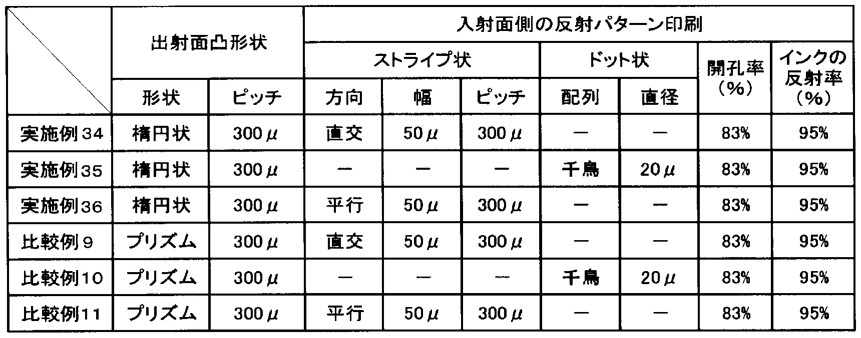
発明の実施の形態 5に係る実施例.
実施例 37〜39、 41〜49、 51の第 2光線方向制御手段は以下の手順により作製し た。出射面に形成する畝状の凸部 2は、切削加工によって幅 0. 3mmの溝状の凹部 を平行に連続して作製した金型を用いて形成する。屈折率 1. 55の紫外線硬化榭脂 を前記金型の切削面に塗布し、その上にメタクリル酸メチルースチレン共重合体であ る屈折率 1. 549の縦 436mm、横 707mm、厚さ 0. 1mmの透明榭脂フィルム(実施 例 51を除く)を重ね、該透明樹脂フィルムの上カゝら紫外線を照射して前記紫外線硬 化榭脂を硬化させた。
[0201] また実施例 37〜39、 41〜49および 51の第 1光線方向制御手段は以下の手順に より作製した。第 1光線方向制御手段 3は、切削加工によって幅 0. 1mmの溝状の凹 部を平行に連続して作製した金型を用いて形成する。屈折率 1. 55の紫外線硬化榭 脂を前記金型の切削面に塗布し、その上にメタクリル酸メチルースチレン共重合体で ある屈折率 1. 549の縦 436mm、横 707mm、厚さ 0. 1mmの透明榭脂フィルムを重 ね、該透明樹脂フィルムの上から紫外線を照射して前記紫外線硬化榭脂を硬化させ た。
[0202] 板状構造物とする場合には、厚さ 2mmの榭脂板表面に粘着剤を介して上記第 1光 線方向制御手段を形成したフィルムを片面に、もしくは第 2光線方向制御手段を形 成したフィルムを片面に、もしくは第 1光線方向制御手段を形成したフィルムと第 2光 線方向制御手段を形成したフィルムの両者を両面に光学的に密着させて得た。実施 例 51以外には透明なアクリル板を用いた。
[0203] 実施例 51は、透明榭脂板の代わりに、光拡散材の微粒子としてシロキサン系重合 体粒子(トスパール 120: GE東芝シリコーン (株)製、数平均粒子径 2 μ m、 CV値 3% )を 0. 04Wt%含有した成型板を用いて、第 1光線方向制御手段を有する部材を作 製する。
実施例 40、 50の第 1光線方向制御手段と第 2光線方向制御手段は以下の手順に より作製した。まず、第 1光線方向制御手段を反転した雌型を切削加工によって幅 0 . 1mmの溝状の凹部を平行に連続して作製する。これと直行する方向に第 2光線方 向制御手段を反転した雌型を切削加工によって 0. 3mmの溝状の凹部を連続して 作製する。
屈折率 1. 55の紫外線硬化榭脂を前記金型の切削面に塗布し、その上にメタクリル 酸メチルースチレン共重合体である屈折率 1. 549の縦 436mm、横 707mm、厚さ 0 . 1mmの透明榭脂フィルムを重ね、該透明樹脂フィルムの上力も紫外線を照射して 前記紫外線硬化榭脂を硬化させた。その後厚さ 2mmの透明なアクリル板表面に粘 着剤を介して上記第 1光線方向制御手段および第 2光線方向制御手段を形成したフ イルムを光学的に密着させた。
[0204] 比較例 12〜15として、第 2光線方向制御手段のみ有する光制御部材を配置するも
のの結果を表 6に示す。正面方向から観察した結果、正面方向の輝度が低下する。 表 6に各実施例および各比較例の構成と輝度測定の結果を示す。
[表 6]

比較例 16として、該光制御部材に代えて通常の微粒子含有の光拡散板を使用し た場合の、評価を実施する。この場合、正面方向の輝度が低下する。またこの照明 装置の出射側に透過型液晶パネルを載せて、画像表示装置とし、正面から観察する この結果、得られた画像は、前記実施例 37の照明装置を用いた場合と比較してか
なり暗いことがわ力る。
[0205] また実施例 39の出射面の凹凸および入射面の凹凸を有する雌型を作製後、温度 60°C、湿度 80%の雰囲気下において吸水率が 0. 4%である材料と 2%である材料 を用いて射出成形により図 31に示す板厚 2mmの板状構造物を作製した。 2つの板 状構造物を温度 45° 、湿度 90%Rhの雰囲気下に放置した結果、吸水率 2%の材 料で作製した板状構造物の反り量が 1. 9mmであるのに対し、吸水率 0. 4%の材料 で作製した板状構造物の反り量は 0. 8mmであった。ここで反り量は、被測定物を平 板の上に置いたとき、平板に対向する面の平板力もの最大高さである。
[0206] 発明の実施の形態 6に係る実施例.
発明の実施の形態 6に係る実施例として、市販の液晶表示装置 (ソニー株式会社 製 商品名 KDL— L32HVX)に搭載されるバックライトユニットの基本構造を用いて 評価した。前記バックライトユニットの構成を図 33に沿って説明する。 X方向の長さ 4 38mm, Y方向の長さ 758mm、 X方向と Y方向に垂直な厚さ方向の長さ 19mmの開 口部を持つ直方体状のハウジング中に、前記ハウジングの出射側の開口部に対向 する位置にある底部を覆うように、出射側に X方向の長さ 714mm、 Y方向の長さ 398 mmの反射板 4が配置されて ヽた。
次に前記反射板の出射側に 3mmの間隔をおいて、該反射板と平行に線状光源を 配置されていた。線状光源 1は、直径 3mm、長さ 700mmの 16本の冷陰極管であり 、 X方向に沿って Y方向に平行に 21. 5mmずつの間隔での配置であった。
[0207] 次に本発明の実施の形態 6に係る光制御部材 2を開口部に被せるように配置した。
前記光制御部材は前記線状光源 1の出射側に 13mmの間隔をお 、て、該反射板 4 と平行に配置した。該光制御部材のサイズは Y方向の長さ 732mm、 X方向の長さ 4 07mmで、 X方向と Y方向に垂直な厚さ方向の凸部の高さを含まない厚み、すなわ ち該光制御部材の入射面から凸部の底部までの厚み Tは 2mmであった。
線状光源 1の中心力 光制御部材 2までの Hは 14. 5mm,隣接する線状光源 1の 中心同士の距離 Dは 25. Ommであった。
[0208] (光制御部材の作製)
本発明の実施の形態 6に係る実施例で用いる光制御部材は、線状光源と対向する
光制御部材の入射面側に平坦である面が形成され、出射面側に式(2)から(8)より 導かれる畝状の凸部が形成されることを特徴とするものであり、前記光制御部材は以 下のようにして作製した。
[0209] (1) ^fe^ f (x) =cos a , N = 50, X = - 25. 0, X =25. 0から式(2)から(8)
min max
より導かれる形状を曲線近似した幅 0. 3mmの凹溝状の形状を切削加工によって平 行に連続して形成し金型を作製した。次に、屈折率 1. 55の紫外線硬化榭脂を前記 金型の切削面に塗布し、その上に押出し成形により作製した縦 407mm、横 732mm 、厚さ 2mmの (メタ)アクリル酸メチルスチレン共重合透明榭脂板 (使用榭脂:電気化 学工業株式会社製 商品名" TXポリマー" TX—800S、屈折率: 1. 549)を重ね、該 透明榭脂板の上から紫外線を照射して前記紫外線硬化榭脂を硬化させることで、畝 状の凸部が形成された光制御部材 (B— 1)を得た。得られた光制御部材 (B— 1)に ついて、 g(X) /g(X) を測定したところ、 0. 87であった。
min max
[0210] (2) 前述の(1)で作製した金型から、屈折率 1. 55の紫外線硬化榭脂を前記金型 の切削面に塗布し、その上に光拡散性微粒子 (GE東芝シリコーン株式会社製 商 品名"トスパール" 2000B、屈折率: 1. 420) 0. 15質量部を前記 (メタ)アクリルスチ レン系共重合透明榭脂板に添加し押し出し成形により作製した縦 407mm、横 732 mm、厚さ 2mmの (メタ)アクリルスチレン系共重合榭脂板を重ね、該榭脂板の上から 紫外線を照射して前記紫外線硬化榭脂を硬化させることで、畝状の凸部が形成され た光制御部材 (B— 2)を得た。得られた光制御部材 (B— 2)につ 、て、 g(X) /g(X)
mm を測定したところ、 0. 92であった。
max
[0211] (3) また、前述の(1)で作製した金型から、屈折率 1. 55の紫外線硬化榭脂を前記 金型の切削面に塗布し、その上に光拡散性微粒子 (GE東芝シリコーン株式会社製 商品名"トスパール" 2000B、屈折率: 1. 420) 1. 0質量部を前記 (メタ)アクリルス チレン系共重合透明榭脂板に添加し押し出し成形により作製した縦 407mm、横 73 2mm,厚さ 2mmの (メタ)アクリルスチレン系共重合榭脂板を重ね、該榭脂板の上か ら紫外線を照射して前記紫外線硬化榭脂を硬化させることで、畝状の凸部が形成さ れた光制御部材 (B— 3)を得た。得られた光制御部材 (B— 3)について、 g(X) /g(
mm
X) を測定したところ、 0. 95であった。
[0212] (突起の影の評価および輝度測定)
(a)突起による影については、目視での評価を行い、その結果を表 7に示した。
(b)照明装置の明るさを示す正面輝度については、色彩輝度計 (株式会社トプコン 社製 BM— 5)により測定し、その結果を表 7に示した。
[0213] (実施例 52)
前記液晶表示装置 (ソニー株式会社製 商品名 KDL— L32HVX)に搭載される ノ ックライトユニット付属の突起に代え、アクリル榭脂 (株式会社クラレ製 商品名"パ ラグラス"透明板 6mmt)を使用して、図 38Aに示す水平断面形状が円形の径 3mm 、先端径 lmm φの突起を旋盤により切削加工し作製したものを、前記照明装置に両 面テープを用いて貼り付け固定した。取り付け位置は、図 36に示すように、線状光源 の中間位置とした。
光制御部材 (B— 1)と組み合わせた時、突起と光制御部材の接する位置に、突起 に起因する影は視認できな力つた。また、表 7に示すように測定輝度は高い値であり 、輝度ムラの改良効果も良好であった。
[0214] (実施例 53)
実施例 52の突起を用い、光制御部材 (B— 2)と組み合わせて、実施例 52と同様に 評価した。突起と光制御部材の接する位置に突起に起因する影は、実施例 52と同 様に視認できな力つた。また、表 7に示すように測定輝度も比較的は高い値であり、 輝度ムラの改良効果も良好であった。
[0215] (比較例 17)
前記液晶表示装置 (ソニー株式会社製 商品名 KDL— L32HVX)に搭載される バックライトユニット付属の突起(白色不透明:形状は実施例 52と同じ)を用いて、光 制御部材 (B— 1)を組み合わせて評価を行った。その結果、突起と光制御部材の接 する位置に、突起に起因する影が明瞭に発生していた。
(比較例 18)
比較例 17の突起を用い、光制御部材 (B— 3)と組み合わせた。光制御部材 (B— 3 )は、比較例 17の光制御部材 (B—1)に比べ光拡散性微粒子を多量に含有するた め、突起と光制御部材とが接する位置に、突起に起因する影は視認できな力つたが
、表 7に示すように測定輝度は低い値となった。すなわち、輝度と画質とのバランスが 取れていないといえる。
[0216] (比較例 19)
前記液晶表示装置 (ソニー株式会社製 商品名 KDL— L32HVX)に搭載される ノ ックライトユニット付属の突起に代え、アクリル榭脂 (株式会社クラレ製 商品名"パ ラグラス"透明板 6mmt)を使用して、図 38Bに示すような水平断面の形状が円形で 先端径 3mm φの突起を旋盤により切削加工し作製したものを、前記照明装置に両 面テープを用いて貼り付け固定した。取り付け位置は、図 36に示すように、線状光源 の中間位置とした。
光制御部材 (B— 1)と組み合わせた時、突起と光制御部材の接する位置に、突起 に起因する影が明瞭に確認された。すなわち、突起の先端径が lmm φを越えたも のであると、画質に悪影響があることが判る。
[表 7]

[0217] 発明の実施の形態 7に係る実施例.
光拡散板は溝状の平行な凹部を設けた金型を用いて、メタクリル酸メチルースチレ ン共重合体を押出成形し、片面に凸部を有する主面サイズが 707mm X 436mmで 厚さ 2mmの光拡散板を得る。凸部の形状は、幅 0. 3mm,深さ 0. 2mmの蒲鋅状で ある。
反射板は溝状の平行な凹部を設けた金型を用いて、メタクリル酸メチル—スチレン
共重合体を射出成形し、片面に凸部を有する主面サイズが 695mm X 412mmで厚 さ 2mmの榭脂板を得る。凸部の形状は、幅 lmm、頂角 40度のプリズム状である。こ のプリズム上に接着剤を薄く塗布し、厚さ 0. 5mmの発泡ペット榭脂を乗せて、加圧 して貼り合わせることで、反射板とする。反射板の反射率は 95%である。
X方向の長さ 458mm、 Y方向の長さ 730mm、 X方向と Y方向に垂直な厚さ方向の 長さ 35mmで、出射側に X方向の長さ 698mm、 Y方向の長さ 416mmの矩形の開 口部を持つ直方体状の白色の ABS榭脂製のハウジングを用意する。
[0218] 次に前記ハウジングの出射側の開口部に対向する位置にある底部を覆うように、前 記反射板を配置する。
次に前記反射板の出射側に 2mmの間隔をおいて、該反射板と平行に線状光源を 配置する。線状光源 1としては直径 3mm、長さ 700mmの複数の冷陰極管を X方向 に沿つて Y方向に平行に配置する。冷陰極管 16本を 22mmずつの間隔をお 、て配 置する。
次に光拡散板を開口部に被せるように配置する。線状光源の中心から光拡散板ま での距離は 15. 5mm、隣接する線状光源の中心同士の距離は 25mmである。
[0219] 正面輝度として、正面方向に対して ± 15度以内の輝度を測定した。測定の手順を 以下に示す。先ず、照明装置の測定点から 500mmの位置に輝度計を設置する。次 に X軸と平行な面内で、測定点力も輝度計までの距離を 500mmに保ち、かつ輝度 計の測定点が移動しな 、ように輝度計の位置および傾きを変えて 、き、各角度での 輝度を測定した。前期角度は拡散板の法線方向に対し、 15度力 15度までであり 、角度の間隔は 1度である。また輝度計の視野は 1度とした。次に、前期各角度での 輝度測定値の平均をとり、 ± 15度の輝度とする。この方法で実施例の正面輝度を測 定すると、 8250cd/m2である。
また光拡散板上に液晶表示素子を重ねることで、画像表示装置である液晶表示装 置を得られる。この画像表示装置では輝度が高ぐ品位の高い画像を確認できる。
[0220] 比較例として、反射板を、メタクリル酸メチルースチレン共重合体の射出成形により 、平滑な主面を持つ主面サイズが 695mmX 412mmで厚さ 2mmの榭脂板の主面 の片方に、接着剤を薄ぐ塗布し、厚さ 0. 5mmの発泡ペット榭脂を乗せて、加圧して
貼り合わせることで、反射板とする以外は同じ条件で、照明装置を作成する。同じよう に正面輝度を測定すると、 7420cd/m2である。また光拡散板上に液晶表示素子を 重ねて、画像表示装置である液晶表示装置を得る。画像を確認すると、実施例と比 較して暗い画像である。
産業上の利用可能性
本発明に係る照明装置は、液晶表示装置等の表示装置を構成するのに有用であ る。
Claims
請求の範囲
X方向と、 X方向に垂直な Y方向とからなる矩形状の出射面を持ち、
反射板と、複数の線状光源と、板状の光制御部材とを備え、
前記反射板は前記 X方向および Υ方向に平行に配置しており、
前記線状光源は前記反射板の出射面側の前記 X方向および Υ方向に平行な 1つ の仮想平面内に配置しており、
かつ、該線状光源は長手方向が Υ方向に平行に配置しており、
かつ、 X方向に沿って等間隔に配列しており、
前記光制御部材は前記配列した線状光源の出射面側に配置し、
かつ、主面は線状光源が配列して 、る前記仮想平面と平行であり、
該光制御部材の主面は、線状光源に対向し該線状光源からの光を受光する入射 面と前記入射面に受光した光を出光する出射面とからなり、
前記出射面は表面に畝状の凸部を複数形成しており、
該凸部は頂部にあたる畝状の稜線が Υ方向に平行に形成されており、かつ、 X方 向に沿って配列して 、る照明装置であって、
前記線状光源の中心間の距離を D、任意の前記線状光源の中心と前記光制御部 材との距離を Η、該線状光源力ゝら光制御部材に入光した光の、 X方向の位置座標 Χ( 光源位置を Χ=0とする)における出射面の法線方向への出光強度を表した関数を f (X)とし、
g (X) =f (X - D) +f (X) +f (X+D) (1)
としたとき、
DZ2≤X≤DZ2の範囲で、 g (X)の最小値である g (X) と最大値である g (X)
min m の比 g (X) /g (X) が 0. 6以上であり、
ax min max
Xの最小値 X が— 3. OD≤X ≤— 0. 5Dの範囲であり、最大値 X が 0. 5D≤
min min max
X ≤3. ODの範囲であり(X および X は、 f (X)の値が X=0である線状光源付近 max min max
を中心に減衰していき、実質 0になるときの両端の座標)、
任意の凸部の X方向の断面形状が、下記の式で表される(2N+ 1)個の傾きの異な る領域 N〜N力 なることを特徴とする照明装置。
δ =(X -X )/(2Ν+1) (2)
max min
X=ix δ (3)
a =Tan-1(X/H) (4)

y =Sin_1((l/n )sina ) (6)
i 2 i
a ocf (X +T-tany ) · cos Φ · cos β /cos a cos( Φ― β ) (7)

N:自然数
ー?^から?^の整数
n:光制御部材の凸部の屈折率
n:光制御部材の基材の屈折率
2
a:領域 iの X方向の幅
Φ:領域 iの出射面に対する斜面の傾き
T:光制御部材の入射面から凸部の底部までの厚み
[2] 請求項 1に記載の照明装置であって、前記凸部の X方向の断面形状を表す領域 N〜Nが X軸の位置座標の順に並んでいることを特徴とする照明装置。
[3] 請求項 1または 2に記載の照明装置であって、前記凸部の X方向の断面形状が、 該凸部を成す(2N+1)個の傾きの異なる領域のうち少なくとも 1組の隣接する 2つの 領域の形状を曲線で近似した形状であることを特徴とする照明装置。
[4] 請求項 1〜3のいずれか 1項に記載の照明装置であって、 X方向と光制御部材の主 面の法線方向に平行な断面内において、出射面の法線方向に対して 30度以内の 角度を成す範囲に出光する光の割合が全出光の 50%以上であることを特徴とする 照明装置。
[5] 請求項 1〜4のいずれか 1項に記載の照明装置であって、前記凸部は、屈折率が 1 . 58以上である材料カゝら構成されることを特徴とする照明装置。
[6] 請求項 1〜4のいずれか 1項に記載の照明装置であって、前記光制御部材に光線 方向を変換する光線方向変換部が設けられ、
前記光線方向変換部は入射面に法線方向から入射した光の 80%乃至 10%の光
の方向を変換するとともに、
前記線状光源から前記入射面に入射した光の 80%以上が前記光線方向変換部 を通過して、前記出射面に形成した凸部に到達することを特徴とする照明装置。
[7] 請求項 1〜4のいずれか 1項に記載の照明装置であって、前記入射面は表面に反 射部材を形成しており、
前記線状光源力 の光の 5〜20%が光源側に反射することを特徴とする照明装置
[8] 請求項 1〜4のいずれか 1項に記載の照明装置であって、
前記光線制御部材は、第 1光線方向制御手段として機能する前記凸部と異なった 他の凸部を有し、
前記凸部は、前記他の凸部に対して第 2光線方向制御手段として機能し、 前記反射板は線状光源に対して発光面と対向する側に、前記 X方向および Y方向 に平行に配置しており、
前記第 1光線方向制御手段は、前記線状光源が配置される仮想平面よりも出射面 側に、前記光源からの光が前記第 1光線方向制御手段と前記第 2光線方向制御手 段との両方に受光されるように配置しており、
前記第 1光線方向制御手段は、受光した光を屈折させて光の Y軸方向の分散を集 光して、出射面側に通過させ、
前記第 2光線方向制御手段は、受光した光を反射、屈折させて光の X軸方向の位 置均一性を高めて、出射面側に通過させることを特徴とする照明装置。
[9] 請求項 1〜4のいずれか 1項に記載の照明装置であって、前記光制御部材と接して 該光制御部材を保持する突起を備え、
前記突起が光透過性材料からなり、突起の水平断面が円形形状であって、光制御 部材と接する突起先端部の直径が lmm以下であることを特徴とする照明装置。
[10] 請求項 1〜4のいずれか 1項に記載の照明装置であって、前記反射板、線状光源、 光制御部材が、前記正面方向に向力つて反射板、線状光源、光制御部材の順に配 置され、
前記反射板および前記光制御部材の主面の外周は前記 XY平面に平行な矩形で
あり、
前記反射板の主面の出光側表面の略全面が前記 X軸に平行で、前記 Y軸に沿つ た、規則的な、凹状および Zまたは凸状のストライプ形状であることを特徴とする照明 装置。
[11] 請求項 1〜10のいずれか 1項に記載の照明装置が備える光制御部材。
[12] 請求項 1〜10のいずれか 1項に記載の照明装置の出射面側に透過型表示素子を 設けたことを特徴とする画像表示装置。
Priority Applications (3)
| Application Number | Priority Date | Filing Date | Title |
|---|---|---|---|
| US11/994,377 US7744235B2 (en) | 2005-06-29 | 2006-06-26 | Lighting device and light control member used therefor and image display device using the lighting device and the light control member |
| EP06767315.2A EP1900996B1 (en) | 2005-06-29 | 2006-06-26 | Lighting device with light control member and image display unit using the above |
| KR1020087002272A KR100928171B1 (ko) | 2005-06-29 | 2006-06-26 | 조명 장치 및 조명 장치에 사용되는 광 제어 부재 그리고이들을 사용한 화상 표시 장치 |
Applications Claiming Priority (6)
| Application Number | Priority Date | Filing Date | Title |
|---|---|---|---|
| JP2005189474 | 2005-06-29 | ||
| JP2005-189474 | 2005-06-29 | ||
| JP2005-222824 | 2005-08-01 | ||
| JP2005222824A JP4684791B2 (ja) | 2005-06-29 | 2005-08-01 | 照明装置、これに使用する光制御部材およびこれらを用いた画像表示装置 |
| JP2005-293549 | 2005-10-06 | ||
| JP2005293549A JP4684838B2 (ja) | 2005-10-06 | 2005-10-06 | 照明装置および光制御手段構造体並びにこれらを用いた画像表示装置 |
Publications (1)
| Publication Number | Publication Date |
|---|---|
| WO2007000962A1 true WO2007000962A1 (ja) | 2007-01-04 |
Family
ID=37595213
Family Applications (1)
| Application Number | Title | Priority Date | Filing Date |
|---|---|---|---|
| PCT/JP2006/312698 Ceased WO2007000962A1 (ja) | 2005-06-29 | 2006-06-26 | 照明装置およびこれに用いられる光制御部材並びにこれらを用いた画像表示装置 |
Country Status (5)
| Country | Link |
|---|---|
| US (1) | US7744235B2 (ja) |
| EP (1) | EP1900996B1 (ja) |
| KR (1) | KR100928171B1 (ja) |
| TW (1) | TWI417612B (ja) |
| WO (1) | WO2007000962A1 (ja) |
Cited By (5)
| Publication number | Priority date | Publication date | Assignee | Title |
|---|---|---|---|---|
| EP2028537A1 (en) * | 2007-08-23 | 2009-02-25 | Sony Corporation | Surface light emitting device and liquid crystal display device using the same |
| JP2009175166A (ja) * | 2007-12-25 | 2009-08-06 | Toppan Printing Co Ltd | 光学シート、バックライトユニットおよび表示装置 |
| JP2011100644A (ja) * | 2009-11-06 | 2011-05-19 | Advan Lighting:Kk | 照明カバー及びその製造方法並びに照明器具 |
| EP2148128A4 (en) * | 2007-05-22 | 2012-02-29 | Sharp Kk | OPTICAL LINK, THIS USING LIGHTING DEVICE, DISPLAY DEVICE AND TELEVISION DEVICE |
| JP2017223988A (ja) * | 2017-08-31 | 2017-12-21 | 株式会社デンソー | 照明用レンズ、照明ユニット及びヘッドアップディスプレイ装置 |
Families Citing this family (25)
| Publication number | Priority date | Publication date | Assignee | Title |
|---|---|---|---|---|
| KR101187552B1 (ko) * | 2006-02-17 | 2012-10-02 | 코오롱인더스트리 주식회사 | 광확산성을 갖는 플레이트 |
| JP4140016B2 (ja) * | 2006-07-28 | 2008-08-27 | ソニー株式会社 | 面発光装置、光学素子及び液晶表示装置 |
| WO2008061125A1 (en) * | 2006-11-15 | 2008-05-22 | 3M Innovative Properties Company | Back-lit displays with high illumination uniformity |
| JP4840779B2 (ja) * | 2007-04-19 | 2011-12-21 | スタンレー電気株式会社 | 面光源装置 |
| EP2255231A1 (en) | 2008-02-07 | 2010-12-01 | 3M Innovative Properties Company | Hollow backlight with structured films |
| TWI365305B (en) * | 2008-06-20 | 2012-06-01 | Coretronic Corp | Backlight module |
| CN101609231B (zh) * | 2008-06-20 | 2012-08-29 | 鸿富锦精密工业(深圳)有限公司 | 背光模组及其光学板 |
| KR101524521B1 (ko) * | 2008-09-19 | 2015-06-02 | 삼성디스플레이 주식회사 | 백라이트 어셈블리 및 그를 포함하는 표시 장치 |
| KR101540216B1 (ko) * | 2008-11-03 | 2015-07-29 | 삼성디스플레이 주식회사 | 광학 부재 및 그를 포함하는 표시 장치 |
| US20100231823A1 (en) * | 2008-12-26 | 2010-09-16 | Dai Nippon Printing Co., Ltd. | Optical sheet, surface light source device, and display device |
| KR100912496B1 (ko) * | 2009-04-23 | 2009-08-17 | 한빔 주식회사 | 백라이트 및 백라이트 광원의 배치방법 |
| JP4947095B2 (ja) * | 2009-06-16 | 2012-06-06 | 住友化学株式会社 | 光取り出し構造体 |
| EP2293140A1 (de) * | 2009-08-01 | 2011-03-09 | Bayer MaterialScience AG | Mehrschichtige Beleuchtungseinheit mit verbesserten Eigenschaften und deren Verwendung |
| EP2488931A4 (en) * | 2009-10-16 | 2013-05-29 | Rpo Pty Ltd | METHOD FOR DETECTING AND LOCATING TOUCH OBJECTS |
| US8583349B2 (en) * | 2009-11-05 | 2013-11-12 | GM Global Technology Operations LLC | Systems and methods for diagnosing oxygen sensors and catalytic converters of exhaust systems |
| KR101184449B1 (ko) * | 2009-12-28 | 2012-09-21 | 제일모직주식회사 | 패턴 도광판, 그 제조방법 및 이를 이용한 액정표시장치 백라이트 유닛 |
| JP5664100B2 (ja) * | 2010-10-07 | 2015-02-04 | ソニー株式会社 | 発光装置及び画像表示装置 |
| USD679444S1 (en) * | 2011-08-19 | 2013-04-02 | S.V.V. Technology Innovation, Inc. | Optical lens array lightguide plate |
| US9675056B2 (en) * | 2014-01-22 | 2017-06-13 | Robert Senter | Illuminated polymer lenticular fishing lures |
| US10620347B2 (en) | 2014-06-13 | 2020-04-14 | Sony Corporation | Light-distribution adjustment sheet and display unit |
| US10317687B2 (en) * | 2014-12-16 | 2019-06-11 | Samsung Electronics Co., Ltd. | Light path adjuster and display device including the same |
| KR101897620B1 (ko) * | 2018-03-21 | 2018-09-12 | 주식회사 옵토전자 | 스마트 iot 조명 장치 및 시스템 |
| CN109447046B (zh) * | 2018-12-27 | 2021-07-23 | 厦门天马微电子有限公司 | 显示面板和显示装置 |
| CN112485912B (zh) * | 2021-01-11 | 2022-05-20 | 成都工业学院 | 基于双显示屏的双视3d显示装置 |
| TWI802155B (zh) * | 2021-12-17 | 2023-05-11 | 友達光電股份有限公司 | 光源模組 |
Citations (9)
| Publication number | Priority date | Publication date | Assignee | Title |
|---|---|---|---|---|
| JPS54155244A (en) | 1978-05-30 | 1979-12-07 | Asahi Chem Ind Co Ltd | Light-scattering synthetic resin |
| JPH01169482A (ja) | 1987-12-25 | 1989-07-04 | Dai Ichi Seiko Co Ltd | 照明装置 |
| JPH0217A (ja) | 1987-11-12 | 1990-01-05 | Mitsubishi Rayon Co Ltd | 面光源素子 |
| JPH10123307A (ja) | 1996-10-25 | 1998-05-15 | Matsushita Electric Works Ltd | 光拡散板およびその製造方法 |
| JPH10283818A (ja) * | 1997-04-02 | 1998-10-23 | Taiho Ind Co Ltd | 面発光体及びその輝度均一化方法 |
| JP2000338895A (ja) | 1999-05-31 | 2000-12-08 | Toshiba Lighting & Technology Corp | 直下式バックライト装置および液晶表示装置 |
| JP2002352611A (ja) | 2001-05-24 | 2002-12-06 | Sharp Corp | 照明装置およびそれを備える表示装置 |
| JP3455884B2 (ja) | 1993-12-28 | 2003-10-14 | 株式会社エンプラス | プリズムシート |
| JP2004319122A (ja) * | 2003-04-11 | 2004-11-11 | Sumitomo Rubber Ind Ltd | 発光装置及び発光装置におけるランプイメージ緩和方法 |
Family Cites Families (9)
| Publication number | Priority date | Publication date | Assignee | Title |
|---|---|---|---|---|
| US5394255A (en) * | 1992-01-27 | 1995-02-28 | Sekisui Kagaku Kogyo Kabushiki Kaisha | Liquid crystal display using a plurality of light adjusting sheets angled at 5 degrees or more |
| US5515253A (en) * | 1995-05-30 | 1996-05-07 | Sjobom; Fritz C. | L.E.D. light assembly |
| JP4133420B2 (ja) * | 2002-03-26 | 2008-08-13 | シャープ株式会社 | バックライト及び液晶表示装置 |
| KR20040062286A (ko) | 2003-01-02 | 2004-07-07 | 삼성전자주식회사 | 프리즘시트 및 이를 사용하는 액정표시장치 |
| US20050002204A1 (en) * | 2003-07-04 | 2005-01-06 | Kun-Lung Lin | Module for uniforming light |
| KR101001972B1 (ko) | 2003-10-13 | 2010-12-17 | 삼성전자주식회사 | 액정표시장치 |
| KR20050052115A (ko) | 2003-11-29 | 2005-06-02 | 엘지.필립스 엘시디 주식회사 | 액정표시장치의 백라이트 유닛 |
| TWI364600B (en) * | 2004-04-12 | 2012-05-21 | Kuraray Co | An illumination device an image display device using the illumination device and a light diffusing board used by the devices |
| TWM290572U (en) * | 2005-09-30 | 2006-05-11 | Radiant Opto Electronics Corp | Light-uniformizing elements for area light source |
-
2006
- 2006-06-26 US US11/994,377 patent/US7744235B2/en not_active Expired - Fee Related
- 2006-06-26 EP EP06767315.2A patent/EP1900996B1/en not_active Not-in-force
- 2006-06-26 KR KR1020087002272A patent/KR100928171B1/ko not_active Expired - Fee Related
- 2006-06-26 WO PCT/JP2006/312698 patent/WO2007000962A1/ja not_active Ceased
- 2006-06-28 TW TW095123254A patent/TWI417612B/zh not_active IP Right Cessation
Patent Citations (10)
| Publication number | Priority date | Publication date | Assignee | Title |
|---|---|---|---|---|
| JPS54155244A (en) | 1978-05-30 | 1979-12-07 | Asahi Chem Ind Co Ltd | Light-scattering synthetic resin |
| JPH0217A (ja) | 1987-11-12 | 1990-01-05 | Mitsubishi Rayon Co Ltd | 面光源素子 |
| JPH01169482A (ja) | 1987-12-25 | 1989-07-04 | Dai Ichi Seiko Co Ltd | 照明装置 |
| JP2852424B2 (ja) | 1987-12-25 | 1999-02-03 | 株式会社エンプラス | 照明装置 |
| JP3455884B2 (ja) | 1993-12-28 | 2003-10-14 | 株式会社エンプラス | プリズムシート |
| JPH10123307A (ja) | 1996-10-25 | 1998-05-15 | Matsushita Electric Works Ltd | 光拡散板およびその製造方法 |
| JPH10283818A (ja) * | 1997-04-02 | 1998-10-23 | Taiho Ind Co Ltd | 面発光体及びその輝度均一化方法 |
| JP2000338895A (ja) | 1999-05-31 | 2000-12-08 | Toshiba Lighting & Technology Corp | 直下式バックライト装置および液晶表示装置 |
| JP2002352611A (ja) | 2001-05-24 | 2002-12-06 | Sharp Corp | 照明装置およびそれを備える表示装置 |
| JP2004319122A (ja) * | 2003-04-11 | 2004-11-11 | Sumitomo Rubber Ind Ltd | 発光装置及び発光装置におけるランプイメージ緩和方法 |
Non-Patent Citations (1)
| Title |
|---|
| See also references of EP1900996A4 * |
Cited By (6)
| Publication number | Priority date | Publication date | Assignee | Title |
|---|---|---|---|---|
| EP2148128A4 (en) * | 2007-05-22 | 2012-02-29 | Sharp Kk | OPTICAL LINK, THIS USING LIGHTING DEVICE, DISPLAY DEVICE AND TELEVISION DEVICE |
| US8355092B2 (en) | 2007-05-22 | 2013-01-15 | Sharp Kabushiki Kaisha | Optical member, illuminating device using the same, display device, and television receiving device |
| EP2028537A1 (en) * | 2007-08-23 | 2009-02-25 | Sony Corporation | Surface light emitting device and liquid crystal display device using the same |
| JP2009175166A (ja) * | 2007-12-25 | 2009-08-06 | Toppan Printing Co Ltd | 光学シート、バックライトユニットおよび表示装置 |
| JP2011100644A (ja) * | 2009-11-06 | 2011-05-19 | Advan Lighting:Kk | 照明カバー及びその製造方法並びに照明器具 |
| JP2017223988A (ja) * | 2017-08-31 | 2017-12-21 | 株式会社デンソー | 照明用レンズ、照明ユニット及びヘッドアップディスプレイ装置 |
Also Published As
| Publication number | Publication date |
|---|---|
| US7744235B2 (en) | 2010-06-29 |
| EP1900996A4 (en) | 2010-04-14 |
| EP1900996B1 (en) | 2013-08-14 |
| TW200707021A (en) | 2007-02-16 |
| EP1900996A1 (en) | 2008-03-19 |
| US20090225538A1 (en) | 2009-09-10 |
| KR100928171B1 (ko) | 2009-11-25 |
| TWI417612B (zh) | 2013-12-01 |
| KR20080026196A (ko) | 2008-03-24 |
Similar Documents
| Publication | Publication Date | Title |
|---|---|---|
| WO2007000962A1 (ja) | 照明装置およびこれに用いられる光制御部材並びにこれらを用いた画像表示装置 | |
| JP4584133B2 (ja) | 照明装置およびこれを用いた表示装置 | |
| CN100460751C (zh) | 面光源装置及其中使用的导光体 | |
| CN100476535C (zh) | 照明装置、图像显示装置及用于这些装置的光扩散板 | |
| KR101058298B1 (ko) | 도광판 및 백라이트부 | |
| JP5428313B2 (ja) | 光均一素子及びそれを用いたバックライトユニットとディスプレイ装置 | |
| WO2003098100A1 (fr) | Source plane de lumiere et guide de lumiere associe | |
| JP2009258621A (ja) | レンズシート、ディスプレイ用光学シート及びそれを用いたバックライト・ユニット、ディスプレイ装置 | |
| JP5310213B2 (ja) | 光均一素子、バックライトユニットおよびディスプレイ装置 | |
| JP5391798B2 (ja) | バックライトユニット及びディスプレイ装置 | |
| JPWO2008029911A1 (ja) | 面光源素子並びにこれに用いる光制御部材およびこれを用いた画像表示装置 | |
| JPWO2008047794A1 (ja) | 照明装置及びそれを用いた画像表示装置 | |
| JP2004111352A (ja) | 面光源装置およびそれに用いる導光体 | |
| JP2010097034A (ja) | マイクロレンズシート、及びそれを用いたバックライトユニット・ディスプレイ装置 | |
| JP2008218418A (ja) | 面光源装置及びそれに用いる導光体 | |
| JP2010266611A (ja) | 光均一素子、光学シート、バックライトユニット及びディスプレイ装置 | |
| JP5012221B2 (ja) | バックライトユニット、およびディスプレイ装置 | |
| JP4515374B2 (ja) | 照明装置及びそれを用いた表示装置 | |
| JP4522938B2 (ja) | 照明装置これが備える光制御部材及びこれを用いた画像表示装置 | |
| JP2011150078A (ja) | 光学シート、バックライトユニットおよびディスプレイ装置 | |
| JP4684838B2 (ja) | 照明装置および光制御手段構造体並びにこれらを用いた画像表示装置 | |
| CN100538152C (zh) | 照明装置及用于该照明装置的光控制构件以及使用这些装置的图像显示装置 | |
| JPH11345513A (ja) | バックライト装置 | |
| JP4522937B2 (ja) | 照明装置、これに使用する光制御部材およびこれらを用いた画像表示装置 | |
| JP5282500B2 (ja) | 光学素子及びそれを用いたバックライトユニットとディスプレイ装置 |
Legal Events
| Date | Code | Title | Description |
|---|---|---|---|
| WWE | Wipo information: entry into national phase |
Ref document number: 200680024038.6 Country of ref document: CN |
|
| 121 | Ep: the epo has been informed by wipo that ep was designated in this application | ||
| WWE | Wipo information: entry into national phase |
Ref document number: 11994377 Country of ref document: US |
|
| NENP | Non-entry into the national phase |
Ref country code: DE |
|
| WWE | Wipo information: entry into national phase |
Ref document number: 2006767315 Country of ref document: EP |
|
| WWE | Wipo information: entry into national phase |
Ref document number: 1020087002272 Country of ref document: KR |