WO2008038791A1 - Câble à fibre optique en plastique et procédé de transmission de signaux utilisant celui-ci - Google Patents
Câble à fibre optique en plastique et procédé de transmission de signaux utilisant celui-ci Download PDFInfo
- Publication number
- WO2008038791A1 WO2008038791A1 PCT/JP2007/069059 JP2007069059W WO2008038791A1 WO 2008038791 A1 WO2008038791 A1 WO 2008038791A1 JP 2007069059 W JP2007069059 W JP 2007069059W WO 2008038791 A1 WO2008038791 A1 WO 2008038791A1
- Authority
- WO
- WIPO (PCT)
- Prior art keywords
- coating layer
- nylon
- pof
- mass
- resin
- Prior art date
- Legal status (The legal status is an assumption and is not a legal conclusion. Google has not performed a legal analysis and makes no representation as to the accuracy of the status listed.)
- Ceased
Links
Classifications
-
- G—PHYSICS
- G02—OPTICS
- G02B—OPTICAL ELEMENTS, SYSTEMS OR APPARATUS
- G02B6/00—Light guides; Structural details of arrangements comprising light guides and other optical elements, e.g. couplings
-
- G—PHYSICS
- G02—OPTICS
- G02B—OPTICAL ELEMENTS, SYSTEMS OR APPARATUS
- G02B1/00—Optical elements characterised by the material of which they are made; Optical coatings for optical elements
- G02B1/04—Optical elements characterised by the material of which they are made; Optical coatings for optical elements made of organic materials, e.g. plastics
- G02B1/045—Light guides
-
- G—PHYSICS
- G02—OPTICS
- G02B—OPTICAL ELEMENTS, SYSTEMS OR APPARATUS
- G02B6/00—Light guides; Structural details of arrangements comprising light guides and other optical elements, e.g. couplings
- G02B6/02—Optical fibres with cladding with or without a coating
- G02B6/02033—Core or cladding made from organic material, e.g. polymeric material
-
- G—PHYSICS
- G02—OPTICS
- G02B—OPTICAL ELEMENTS, SYSTEMS OR APPARATUS
- G02B6/00—Light guides; Structural details of arrangements comprising light guides and other optical elements, e.g. couplings
- G02B6/44—Mechanical structures for providing tensile strength and external protection for fibres, e.g. optical transmission cables
Definitions
- the present invention relates to a plastic optical fiber cable having a coating layer made of a nylon resin, and in particular, a plastic optical fiber cable excellent in long-term heat resistance in a high temperature environment of about 100 to 110 ° C, and This optical fiber cable and the light emission center
- the present invention relates to a signal transmission method using a combination of visible light emitting diodes in the range of 500 nm to 600 nm.
- a silica-based optical fiber capable of performing excellent optical transmission over a wide wavelength range has been put to practical use mainly in a trunk line system.
- This silica-based optical fiber is expensive. And workability is low. Therefore, plastic optical fiber (hereinafter abbreviated as POF), which has the advantages of being cheaper, lighter, large-diameter, and easy to handle and handle, can be used for lighting, sensor, FA, etc. It has been put to practical use in the field of indoor wiring applications such as OA and LAN.
- POF plastic optical fiber
- step index type (SI type) POFs having a core-clad structure with polymethyl methacrylate (PMMA) as the core material and a low refractive index fluorine-containing olefinic copolymer as the cladding material.
- SI type step index type
- POF cable with a coating layer on the outer periphery of the cable can be used for high-speed data communication, and is being put to practical use as LAN communication wiring in automobiles from the viewpoint of weight reduction, cost reduction of communication system, and excellent electromagnetic noise countermeasures. .
- Patent Document 2 Japanese Patent Laid-Open No. 11 242 142 describes a primary coating layer made of a black polyamide resin on the outer periphery of POF, and a colored polyamide.
- POF cables with a secondary coating layer made of resin have been proposed, and examples of polyamide resins include nylon 6, nylon 11, and nylon 12.
- Patent Document 3 (Pamphlet of International Publication No. 01/48526) and Patent Document 4 (Japanese Patent Laid-Open No. 2003-315 638) describe an adhesion layer made of a material containing a polyamide polymer on the outer periphery of a POF strand.
- a POF cable in which a primary coating layer and a secondary coating layer are sequentially formed is disclosed, and nylon 6, nylon 66, nylon 11, and nylon 12 are listed as polyamide polymers.
- Patent Document 5 Japanese Patent Laid-Open No. 2003-255202 proposes a POF cable in which a coating layer made of a polyamide-based resin containing a rare metal-based inorganic pigment is formed on the outer periphery of a POF strand.
- polyamide resins polyamide 11, polyamide 12, polyamide 6/12, polyamide 66, polyamide 66/6 are listed.
- Patent Document 6 Japanese Unexamined Patent Application Publication No. 2004-226 925 proposes a POF cable in which a coating layer made of a polyamide-based resin containing an ultramarine inorganic pigment is formed on the outer periphery of a POF strand.
- the resin include nylon 11, nylon 12, nylon 6, and nylon 66.
- Patent Document 7 Japanese Patent Application Laid-Open No. 2000-231045 includes a primary coating layer made of a nylon resin having a melting point of 200 ° C. or less on the outer periphery of a POF strand, and the outer periphery of the primary coating layer. Describes a POF cable with a secondary coating layer made of nylon 12 or a chlorinated resin with an oxygen index of 25 or higher!
- a polyamide resin such as nylon 12 is industrially obtained by a polycondensation reaction of an amine and a carboxylic acid.
- the polymerization of the polyamide resin is a chemical equilibrium reaction, it is inevitable that monomers and oligomers derived from the raw material of the polyamide resin remain in the produced polymer.
- a primary coating layer made of polyamide 11, polyamide 12, or polyamide 6-12 resin is provided so as to be in contact with the POF strand as described in the above-mentioned patent document.
- the POF cable that is provided or provided with a secondary coating layer made of these polyamide-based resins has a phenomenon that the transmission loss of POF increases remarkably when left in a high temperature environment of 100 ° C or higher for a long time. It was seen.
- the cause of the increase in the transmission loss is that the residual monomers and oligomers derived from these raw materials, the primary coating layer and the secondary coating layer It has been found that it has dissolved and diffused inside the POF strands, causing an increase in POF transmission loss.
- Examples of the monomer derived from the above-mentioned polyamide-based resin raw material include an aliphatic diamino acid compound, an aliphatic dicarboxylic acid compound, an amino-aliphatic carboxylic acid compound and the like constituting the polyamide-based resin.
- Nylon 1 1 has 1 1 aminoundecanoic acid
- Nylon 12 has 12 aminododecanoic acid
- Nylon 6-12 has hexamethylenediamine and dodecanedioic acid salt
- Nylon 610 has hexamethylenediamine.
- nylon 6 Sebacate, ⁇ -aminocaproic acid for nylon 6, hexamethylenediamine and adipic acid for nylon 66, 1,10-decandiamine and 1,12-dodecandiamine for nylon 1010, 1,12-decandiamine and 1 for nylon 1012 , 12-dodecanedioic acid.
- a cyclic ratata compound in which the molecular chain terminal of the aminocarboxylic acid compound has an ester cyclization bond in the molecule and an amide bond (one CONH—) in the ring.
- nylon 12 includes lauryl ratata.
- the monomer derived from the raw material includes a low molecular compound produced as a by-product during the raw material synthesis.
- the above-mentioned raw material monomer (the above-mentioned aliphatic diamino acid compound, the aliphatic dicarboxylic acid compound is used in the process of the polycondensation reaction during the production of the polyamide-based resin.
- Amino aliphatic carboxylic acid compounds, etc. two or more molecular chain ends are ester-bonded between the molecules, and the amino chain (one)) and the force lpoxyl group (one COOH) or both
- a compound having one functional group or the end of the molecular chain of the compound is further ester-cyclized in the molecule to enter the ring.
- the terminal amino group has a high affinity with the fluorine-containing olefin-based polymer, and the inside of the cladding layer made of the fluorinated olefin-based polymer. It is easy to stay in. As a result, the transparency of the clad material tends to decrease, and the transmission characteristics of the POF cable tend to deteriorate significantly.
- the monomer or oligomer is a cyclic rattan compound, it easily moves to the vicinity of the interface on the inner layer side (core or first cladding layer) of the cladding layer to form a particulate structure. For this reason, when the core-cladding interface or the clad is multi-layered, structural irregularities at the clad-cladding interface increase and the transmission characteristics of the POF cable tend to be remarkably deteriorated.
- POF cables are required to have excellent heat resistance, and in particular, when POF cables are used in automobiles, they are used for a long period of time exceeding 5000 hours in a 105 ° C environment. A small increase in transmission loss is required.
- conventional POF cables such as those described in the above-mentioned patent documents have difficulty in satisfying the required performance because transmission loss increases due to the reasons described above when placed in a high temperature environment for a long time. It was.
- Patent Document 7 Japanese Patent Laid-Open No. 2000-2310405 discloses, as a comparative example for the proposed invention (Comparative Example 2 and Comparative Example 8), a primary coating material made of nylon 66 resin on the outer periphery of POF. Directly formed POF cable is disclosed!
- the high melting point polyamide 66 resin is coated directly on the outer periphery of the POF strand at a high coating temperature, resulting in a change in the POF outer shape and an increase in transmission loss, resulting in a high melting point nylon.
- Resin is suitable as a POF coating material! / [0020]
- LEDs light-emitting diodes
- LEDs that currently have a main emission center wavelength of around 650 nm are long-term above 100 ° C.
- the heat resistance of is insufficient at present. The reason for this is that such LEDs are formed from GaAlAs-based materials, and their A1 content is high! /, And the heat resistance of the LED itself tends to decrease.
- Patent Document 8 Japanese Patent Laid-Open No. 2001-151867.
- Patent Document 9 Japanese Patent Application Laid-Open No. 2001-21737
- Has a light transmission of 750 to 850 nm A signal transmission system comprising a POF having an LED and a polycarbonate resin as a core material is disclosed.
- An LED having an emission center in the near-infrared wavelength region has a low component ratio of the A1 component, so the LED itself has excellent heat resistance at 100 ° C or higher.
- the signal transmission quality system described in the above patent document can stabilize the transmission loss for a sufficiently long period of time with little change in the transmission loss over time even in a high temperature environment of 100 ° C or higher. there were.
- the transmission loss at 930 to 990 nm of POF having the norbornene resin described in Patent Document 8 as a core material is in the 6000 dB / km range, and the polycarbonate resin described in Patent Document 9
- the transmission loss of POF at 750 to 850 nm in the core material is 1000 dB / km, and the transmission loss of POF described in both patent documents is extremely high. Was insufficient.
- visible light LEDs having an emission center wavelength of 600 nm or less include InGaN systems (emission center wavelengths of 505 nm and 520 nm), PGaN systems (emission center wavelengths of 565 nm), InGaAlP systems (emission center wavelength of 590 nm), etc. It is known that it does not contain the A1 component, which causes the heat resistance of the LED to be reduced, or even if it contains it, the composition ratio is small. ing. Furthermore, the core material is PMMA resin.
- the POF has a transmission loss window (80 to 90 dB / km) near a wavelength of 570 nm, and its transmission loss value is significantly lower than that of a window near a wavelength of 650 ⁇ m (about 130 to 140 dB / km). There is also.
- An object of the present invention is to provide a plastic optical fiber cable having a small increase in transmission loss under a high temperature environment and excellent in long-term heat resistance, and a signal transmission method using the same.
- a plastic optical fiber having a core and one or more clad layers formed on the outer periphery of the core, and the outer periphery thereof are provided.
- a plastic optical fiber cable having a coating layer comprising:
- the core is formed of a polymethyl methacrylate or a copolymer mainly composed of methyl methacrylate,
- the clad layer has at least an outermost layer comprising a fluorine-containing olefin-based resin containing a tetrafluoroethylene unit and having a crystal melting heat of 40 mj / mg or less in differential scanning calorimetry (DSC),
- the coating layer is composed of a protective coating layer, a light blocking coating layer, and a functional coating layer in this order from the inside.
- the functional coating layer has a nylon resin composition having a crystalline melting point in the range of 215 ° C to 280 ° C.
- the functional coating layer is a brominated flame retardant having an amount of melamine cyanurate in the range of 3% by mass to 40% by mass or a bromine atom content in the range of 1.5% by mass to 30% by mass. In the range of 0.1% by mass to 10% by mass of the chromatic inorganic pigment. Formed from a nylon-based resin composition having a crystalline melting point by differential scanning calorimetry (DSC) in the range of 215 ° C to 280 ° C,
- the light shielding coating layer contains at least one nylon resin of nylon 11 and nylon 12 as a main component, and the total content of the monomer compound and the oligomer compound derived from the nylon resin contained is 1.5 mass. % Of the resin composition in the range of
- the protective coating layer is made of at least one resin material selected from polybutylene terephthalate resin, methyl (meth) acrylate resin, styrene resin, and vinylidene fluoride homopolymer, and is a plastic optical fiber.
- a cable is provided.
- the plastic optical fiber cable as described above, wherein the functional coating layer is formed from a nylon-based resin composition containing at least one of nylon 6 and nylon 66 as a main component. Is done.
- the plastic optical fiber cable as described above, wherein the functional coating layer is formed of a nylon resin composition containing antimony oxide in an amount of 20% by mass or less.
- the outer diameter of the plastic optical fiber is Am
- the thickness of the protective covering layer is am
- the thickness of the light shielding coating layer is bm
- the functional coating layer Thick is (111), the following formulas (i) to (iii)
- a plastic optical fiber having a core and one or more cladding layers formed on the outer periphery of the core, and its outer periphery
- a plastic optical fiber cable having a coating layer on
- the core is formed of a polymethyl methacrylate or a copolymer mainly composed of methyl methacrylate
- the clad layer has at least an outermost layer comprising a fluorine-containing olefin-based resin containing a tetrafluoroethylene unit and having a crystal melting heat of 40 mj / mg or less in differential scanning calorimetry (DSC),
- the coating layer is composed of a protective coating layer, a light blocking coating layer, and a functional coating layer in this order from the inside.
- the functional coating layer has a melting point by differential scanning calorimetry (DSC) in the range of 240 ° C to 280 ° C. 5. Temperature measured by the method specified in IS014663-2: 1999 (Annex C) T oxygen transmission rate P at (K) (cm 3 ⁇ cm / (cm 2 ⁇ sec ⁇ Pa)) is the following formula (a)
- the light shielding coating layer contains at least one nylon resin of nylon 11 and nylon 12 as a main component, and the total content of the monomer compound and the oligomer compound derived from the nylon resin contained is 1.5 mass. % Of the resin composition in the range of
- the protective coating layer is at least one selected from a polybutylene terephthalate resin, a methyl (meth) acrylate resin, a styrene resin, a vinylidene fluoride homopolymer, and a copolymer containing a polyethylene unit and a polybutyl alcohol unit.
- a plastic optical fiber cable formed from a resin material is provided.
- the functional coating layer is formed from a nylon resin composition having a crystallinity in the range of 30% to 55%! Bull is provided.
- the functional coating layer is formed of a nylon resin composition having an average diameter of spherulite size by microscopic observation in the range of 0.01 m or more and 40 m or less.
- a plastic optical fiber cable as described above is provided.
- the functional coating layer is formed from a nylon resin composition mainly composed of nylon 66.
- the functional coating layer is formed of the nylon resin composition containing a crystallization accelerator in a range of 0.01 mass% to 10 mass%.
- a plastic optical fiber cable is provided.
- the functional resin layer comprises a nylon-based resin composition containing bromine-containing polystyrene so that the bromine atom content is in the range of 1.5 mass% to 30 mass%.
- a plastic optical fiber cable as defined above is provided.
- the plastic optical fiber cable as described above wherein the functional coating layer is formed from a nylon resin composition containing antimony oxide in an amount of 20% by mass or less.
- the functional coating layer is formed from a nylon resin composition containing an inorganic pigment as a colorant in the range of 0.1% by mass to 10% by mass.
- a plastic optical fiber cable is provided.
- the plastic optical fiber cable has a light emission center at a wavelength of 5
- a signal transmission method characterized by transmitting a signal in combination with a visible light emitting diode having a range of OOnm to 600nm.
- the present invention it is possible to provide a plastic optical fiber cable that has a small increase in transmission loss in a high temperature environment and has excellent long-term heat resistance, and a signal transmission system using the same.
- FIG. 1 is a cross-sectional view showing a plastic optical fiber cable according to the present invention.
- FIG. 2 is a cross-sectional view showing an apparatus for measuring the pulling strength of a coating layer of a plastic optical fiber cable.
- FIG. 3 Shows the total wavelength transmission loss of POF cable at the initial stage of Reference Example 3 and after 5000 hours at 105 ° C.
- FIG. 4 Shows the total wavelength transmission loss of POF cable at the initial stage of Example 90 and after 5000 hours at 105 ° C.
- FIG. 5 shows the total wavelength transmission loss of POF cable in Example 93 at the initial stage and after 105 hours at 105 ° C.
- the inventors of the present invention include a cause of an increase in transmission loss of a plastic optical fiber cap (hereinafter referred to as "POF cable”) in a high temperature (or high temperature and high humidity) environment! /
- POF cable plastic optical fiber cap
- POF strand plastic optical fiber
- a coating layer capable of preventing the migration of low-molecular compounds (monomers and oligomers) is provided, and the low-molecular compound (monomer) is also provided in the coating layer itself.
- oligomers to reduce the increase in Rayleigh scattering by providing a coating layer (light blocking coating layer, functional coating layer) that does not easily release low-molecular-weight compounds. It was found that the increase can be suppressed.
- the wavelength of 600 nm is not limited to the POF wavelength of 650 nm alone. We have also seen that it is possible to suppress the following increase in transmission loss.
- the POF cable of the present invention has a core and a POF strand 101 having a cladding layer formed of one layer or two or more layers formed on the outer periphery thereof, and on the outer periphery thereof from the inner layer side.
- a coating layer comprising a protective coating layer 102, a light shielding coating layer 103, and a functional coating layer 104.
- the core is made of polymethyl methacrylate (homopolymer of methyl methacrylate) or a copolymer having methyl methacrylate as a main component, and the clad layer includes a tetrafluoroethylene unit. And a layer made of a fluorinated olefin-based resin having a heat of crystal melting of 40 mj / mg or less in differential scanning calorimetry (DSC) at least as an outermost layer.
- DSC differential scanning calorimetry
- the protective coating layer includes a polybutylene terephthalate resin, a methyl (meth) acrylate resin, a styrene resin having a styrene unit as a main constituent unit, and vinyl fluoride. It is formed from at least one selected from redene homopolymers.
- polybutylene terephthalate resin is particularly preferable.
- the light blocking coating layer is formed from a nylon resin composition containing at least one of nylon 11 and nylon 12 as a main component.
- the total content of the monomer compound and oligomer compound derived from the raw material of the nylon resin contained in the nylon resin composition is preferably in the range of 1.5% by mass or less.
- This nylon resin composition can be colored black by containing a light-shielding agent.
- the functional coating layer has a crystalline melting point by differential scanning calorimetry (DSC) in the first form in the range of 215 ° C to 280 ° C, and in the second form, 240 ° C to 280 ° C. It is formed from a nylon resin composition in the range.
- This functional coating layer is preferably made of at least one of nylon 6 and nylon 66, preferably made of a nylon resin composition mainly composed of at least one selected from nylon 6, nylon 66, nylon 610, and nylon 6/66. More preferably, the main component is a nylon resin composition.
- This functional coating layer can contain a chromatic inorganic pigment to enhance the discrimination of the POF cable.
- a brominated flame retardant or melamine cyanurate can be included in order to increase the flame retardancy of the POF cable.
- the brominated flame retardant is preferably a brominated compound having a 1% mass reduction temperature of 300 ° C or higher measured by the differential thermal and thermogravimetric simultaneous measurement method (TG / DTA), and has a molecular weight of 900 At least one selected from tetrabromobisphenol A derivative compounds having a molecular weight of 900 or more and 60,000 or less, or poly (pentabromobenzyl acrylate) having a number average molecular weight of 900 or more and 60,000 or less. Can be suitably used.
- TG / DTA differential thermal and thermogravimetric simultaneous measurement method
- POF strands core, clad
- light shielding coating layer protective coating layer
- functional coating layer that constitute the POF cable of the present invention
- the material constituting the core of the POF strand portion is 100 ⁇ ; From the viewpoint of satisfying long-term heat resistance at around 105 ° C, polymethyl methacrylate (PMM A) or co-polymer consisting of methyl methacrylate (MMA) units and one or more types of bulle monomer units Use coalescence.
- this copolymer and PMMA are called PMMA resins.
- PMMA is preferred because of its excellent balance between transparency and mechanical strength.
- the core material is a copolymer of MMA and a bull monomer
- the content of MMA units is preferably 50% by mass or more, preferably 60% by mass or more, from the viewpoint of ensuring sufficient transparency.
- a copolymerization component for MMA it is possible to appropriately select a component that has been proposed so far as a raw material for a POF core material such as methacrylic acid ester and acrylic acid ester. it can.
- the clad formed on the outer periphery of the core may be formed from one layer! /, Or may be formed from two or more layers.
- This cladding has a mechanical property to function as a protective material for the core or inner cladding, heat resistance, chemical resistance, impact resistance, and a low refractive index that can sufficiently reduce optical loss during bending.
- at least the outermost layer has a layer made of a fluorine-containing resin.
- a fluorinated olefin-based resin a fluorinated olefin-based polymer having at least a tetrafluoroethylene (TFE) unit and a crystal melting heat of 40 mj / mg or less is used.
- Fluorine-containing olefin-based polymers containing TFE units include TFE units, vinylidene fluoride (VdF) units, hexafluoropropylene (HFP) units, perfluoroalkyl fluoro ethers (FVE). ) A copolymer obtained by copolymerizing at least one of the units, a copolymer of VdF units, TFE units, and hexafluoroacetone units, of TFE units, HFP units, and ethylene units. Examples include, but are not limited to, copolymers. As the copolymerization component for TFE, Vd F units, HFP units or FVE units are particularly preferred in terms of cost, transparency and heat resistance! /.
- a resin containing at least one of a VdF unit and an HFP unit in a fluorine-containing olefin-containing polymer containing a TFE unit has excellent stability during melt spinning of POF! It is preferable.
- fluorine-containing olefin-containing polymer containing TFE units include binary copolymers consisting of 60 to 90% by mass of VdF units and 10 to 40% by mass of TFE units, and VdF units 10 to 60%. Ternary copolymer consisting of 5% by mass, 20-70% by mass of TFE units, 5-35% by mass of HFP units, 5-25% by mass of VdF units, 50-80% by mass of TFE units, and 5 units of FVE units.
- Ternary copolymer consisting of ⁇ 25% by mass, ethylene unit 5 ⁇ 60% by mass, TFE unit 25 ⁇ 70% by mass, HFP unit 5 ⁇ 45% by mass, VdF unit 10 ⁇ Quaternary copolymer consisting of 30% by mass, TF E unit 40-80% by mass, HFP unit 5-40% by mass, FVE unit 0.;!-15% by mass, TFE unit 40-90% by mass And a binary copolymer composed of 10 to 60% by mass of FVE units, a binary copolymer composed of 30 to 75% by mass of TFE units and 25 to 70% by mass of HFP units, and the like.
- CF 2 CF- (OCF 2 CF (CF 3 )) aO-Rf 2 (1)
- Rf represents an alkyl group having 1 to 8 carbon atoms, a fluoroalkyl group, an alkoxylalkyl group or a fluoroalkoxylalkyl group, and a is an integer of 0 to 3.
- CF 2 CF (OCF 2 CF (CF 3 )) n O (CF 2 ) m CF 3 (3)
- n is an integer from 0 to 3
- m is an integer from 0 to 3
- n is an integer from 0 to 3
- CF CFOCF
- CF CFOCF CF
- CF CFOCF CF
- CF CFOCF CF
- the unit of at least one kind of compound thus obtained is preferable as the FVE unit because raw materials can be obtained at low cost.
- a resin having a crystal melting heat value of 40 mj / mg or less as the fluorine-containing olefin-based polymer forming the outermost clad layer, and a resin having a value of 20 mJ / mg or less.
- a resin of 15 mj / mg or less is more preferable. If the heat of crystal melting is too high, the crystallinity of the resin will increase, and the transparency of the resin will decrease in a high temperature environment, which may increase the initial transmission loss of the POF cable and the high temperature environment. .
- a resin having a heat of crystal melting within the above range for example, lmj / mg or more can be used.
- the resin for forming the inner clad on the inner layer side is proposed as a clad material for POF such as a fluorinated metatalylate polymer and a vinylidene fluoride polymer.
- the material can be selected as appropriate.
- a fluorinated methacrylate polymer is preferable because it is easy to adjust the refractive index, has excellent transparency and heat resistance, and is excellent in flexibility and workability.
- fluorinated metatalylate-based polymer for example, as a polymer excellent in flexibility and workability while having good transparency and heat resistance,
- X is a hydrogen atom, a fluorine atom, or a methyl group
- R is a carbon atom having 1 to 12 carbon atoms
- m represents an integer of 1 or 2;
- the unit (A) of the (meth) acrylic acid fluorinated alkyl ester has the following general formula (7):
- X represents a hydrogen atom or a methyl group
- Y represents a hydrogen atom or a fluorine atom
- m represents 1 or 2
- n represents an integer of 1 to 12
- X represents a hydrogen atom or a methyl group
- R 1 and R 2 are the same or different fluorocarbons.
- R1 represents a hydrogen atom, a methyl group or a fluorine atom; m represents an integer of 1 or 2; )
- Examples of general formula (7) include 2,2,2 trifluoroethyl (meth) acrylate (3FM), 2,2,3,3 tetrafluoropropyl (meth) acrylate (4FM) ), (Meth) acrylic acid 2,2,3,3,3 pentafunole-old ropropinole (5FM), (meth) atalinoleic acid 2,2,3,4,4,4-hexafluorobutyl (6FM), (Meth) acrylic acid 1H, 1H, 5H Octafluoropentyl (8FM), (Meth) acrylic acid 2 (perfluorobutyl) ethyl (9FM), (meth) acrylic acid 2 (perfluorohexyl) ethyl (13FM) ), (Meth) acrylic acid 1H, 1H, 9H Hexadecafluorononyl (16FM), (meth) acrylic acid-2 (perfluorooctinole) ethyl (1 7FM), (meth) acrylic acid (me
- a branched fluorinated alkyl group such as hexafluoroneopentyl (meth) acrylate or hexafluoroisobutyl (meth) acrylate is present in the side chain (meta ) Acrylic acid fluorinated ester.
- the unit (B) of the monomer copolymerizable with the monomer of the unit (A) methyl (meth) acrylate, ethyl (meth) acrylate, butyl (meth) acrylate, etc.
- one or more compounds may be appropriately selected so as to satisfy the transparency and heat resistance of the clad material.
- methyl (meth) acrylate is copolymerized with (meth) atalinoleic acid fluorinated alkyl ester, thereby improving the transparency and heat resistance of the cladding material. From the viewpoint of improving the balance and mechanical strength in a well-balanced manner.
- methacrylic acid in the fluorinated metatalylate polymer in the range of 0.5 to 5% by mass, the adhesion to both the POF core material and the resin of the outermost cladding layer is improved. it can.
- the unit of (meth) acrylic acid-2- (perfluorooctyl) ethyl (17FM) is 10 to 40% by mass, and (meth) acrylic acid 2, 2, 2 Trifluoroethyl (3FM), (Meth) acrylic acid 2, 2, 3, 3 Tetrafluoropropyl (4F M), (Meth) acrylic acid 2, 2, 3, 3, 3 Pentafluoropropyl (5FM) )
- (Meth) acrylic acid 2, 2, 3, 3 Tetrafluoropropyl (4F M) (Meth) acrylic acid 2, 2, 3, 3, 3 Pentafluoropropyl (5FM)
- a refractive index in the range of 1.39 to; 1.43. preferable.
- the clad layer may be formed of two or more layers.
- the first clad is used as the inner clad between the outermost clad and the core. It is preferable to have a two-layer structure including only the first cladding and the second cladding layer as the outermost cladding around the first cladding.
- the refractive index of the core is n
- the refractive index of the inner-layer clad (first clad) is n
- the refractive index of the outermost clad (second clad) is n.
- n, n, and n are the following relational expressions (iV)
- the refractive index in the present invention means a refractive index at 25 ° C. by sodium D line.
- the POF cable of the present invention includes a nylon resin (polyamide-based resin) containing a light-shielding agent such as carbon black around the outer periphery of the POF strand having the above-described core-clad structure in order to prevent external light from entering.
- a light shielding coating layer made of a resin is provided.
- nylon 11 (homopolymer) and nylon 12 (homopolymer) excellent in heat resistance, flex resistance, chemical resistance and the like are suitable.
- Nylon 11 and Nylon 12 have good moldability in the coating process and have an appropriate crystal melting point. Therefore, the transmission performance of POF cables using PMMA-based resin as a core material can be easily reduced. OF wire can be coated.
- These resins are also excellent in dimensional stability and adhesion to POF wires, so they are effective in generating heat shrinkage and pistoning, which are particularly problematic when POF cables are used in automotive LAN applications. It is preferable because it can be prevented.
- the adhesion between the POF strand and the light shielding coating layer specifically means the adhesion between the protective coating layer and the light shielding coating layer, which will be described later, provided on the outer periphery of the POF strand. To do.
- the light blocking coating layer may be formed from one type of nylon resin, or two or more types may be mixed and used. Further, if necessary, a polymer or a compound other than the nylon resin can be added and used. Thus, when other components such as other polymers and compounds are blended, it is preferable to add the other components within a range of less than 50% by mass. When the amount of other components is more than 50% by mass, the properties of nylon 11 and nylon 12 become insufficient, so the battery fluid resistance tends to decrease and the thermal dimensional stability of the POF cable tends to decrease.
- the material constituting the light shielding coating layer in the present invention is mainly composed of a nylon resin.
- the content of the nylon resin component when containing both nylon 11 and nylon 12 is preferably 50% by mass or more, more preferably 70% by mass or more, and more preferably 80% by mass or more. preferable.
- a nylon resin such as nylon 12 is industrially obtained by a polycondensation reaction of an amine and a carboxylic acid.
- polymerization of the nylon resin is a chemical equilibrium reaction, it is inevitable that monomers and oligomers derived from the raw material of the nylon resin remain in the produced polymer.
- a POF cable provided with a primary coating layer made of nylon 11 or nylon 12 force so as to be in contact with the POF strand is a long-term environment at a high temperature of 105 ° C. When left unattended, POF transmission loss increased significantly.
- the cause of the increase in the transmission loss is the residual monomer and oligomer derived from these raw materials, the primary coating layer and the secondary coating. It has been found that it has dissolved and diffused from the layer into the POF strand, causing an increase in POF transmission loss! /.
- this phenomenon occurs when the outermost layer force of the clad is a fluorine-containing olefin-based resin containing a unit of tetrafluoroethylene (TFE), and the heat of crystal melting is a certain value or more. The increase in transmission loss was found to be remarkable.
- TFE tetrafluoroethylene
- POF cables are required to have excellent heat resistance. Especially when POF cables are used in automobiles, they are used for a long period of time exceeding 5000 hours at 105 ° C. A small increase in transmission loss is required.
- the light shielding coating layer is formed of a material mainly composed of a nylon-based resin. It is necessary to use a resin having a total content of monomeric compounds and oligomeric compounds derived from nylon resins contained in the range of 1.5% by mass or less.
- the total content of the monomeric compound and the oligomeric compound is preferably in the range of 1.3% by mass or less, more preferably in the range of 1.0% by mass or less, and 0.8% by mass or less. If it is a range, it is especially preferable.
- the monomer by the protective coating layer is more sufficient.
- the blocking effect of the compound and oligomer compound can be obtained.
- the content of the monomer compound and oligomer compound in the light shielding coating layer is too large, particularly when it is more than 1.5% by mass, the blocking effect of the monomer compound and oligomer compound by the protective coating layer becomes insufficient.
- the total content of the monomer compound and the oligomer compound in the light blocking layer is, for example, a content of 0.1% by mass or more, further 0.5% by mass or more. Can sufficiently block these compounds.
- the monomer compound in the nylon resin constituting the light blocking coating layer is, as described above, an aliphatic diamino acid compound, an aliphatic dicarboxylic acid compound, an amino aliphatic carboxylic acid compound, which are raw material monomers of the nylon resin.
- Nylon 11 includes 11 aminoundecanoic acid
- nylon 12 includes 12-aminododecanoic acid.
- this monomer compound includes an aminocarboxylic acid compound in which the chain end of the molecular chain is esterified in the molecule and a cyclic ratata compound having an amide bond (CONH) in the ring. Products are also included.
- a cyclic ratatam compound nylon 12 includes lauryllatatam.
- the oligomer compound in the nylon resin constituting the light blocking coating layer is the above-mentioned raw material monomer (the above-mentioned aliphatic diamino acid compound) in the process of the polycondensation reaction during the production of the nylon-based resin.
- Aliphatic dicarboxylic acid compounds, amino aliphatic carboxylic acid compounds, etc. two or more molecular chain ends are ester-bonded between the molecules, and an amino group (one NH) and a carboxyl group (one COOH) are attached to the molecular chain ends.
- the terminal amino group has high affinity with the fluorine-containing olefin-based polymer, and the inside of the clad layer made of the fluorinated olefin-based polymer. It is easy to stay in. As a result, the transparency of the clad material tends to decrease, and the transmission characteristics of the POF cable tend to deteriorate significantly.
- the monomer or oligomer In the case of a tom compound, it tends to move to the vicinity of the interface on the inner layer side (core or first cladding layer) of the cladding layer to form a particulate structure. Therefore, when the POF core-cladding interface or the clad is multi-layered, structural irregularities at the clad-cladding interface increase, and the transmission characteristics of the POF cable tend to be remarkably deteriorated.
- a method for reducing the monomer compound and oligomer compound in the nylon resin there are a method for controlling the temperature, moisture content, raw material / product concentration in the reaction system, polymerization of the nylon resin, and polymerization. It is possible to use known techniques such as a method of supplying a later nylon-based resin to a hot water extraction tower and performing counter-current extraction with hot water, or a method of removing monomer from a molten polyamide resin under high temperature and high vacuum. it can.
- nylon 12 is Daia mide—L1600, LI 640 (manufactured by Daicel Degussa). (Trade name) and nylon 11 include Rilsan BMF-0 (trade name) from Arkema.
- One of the features of the POF cable of the present invention is that it prevents the monomer compound and / or oligomer compound derived from the raw material contained in the nylon resin forming the light shielding coating layer from transferring to the POF strand. Therefore, a protective coating layer is provided between the POF strand and the light shielding coating layer.
- a resin selected from a methyl (meth) acrylate resin, a styrene resin, a vinylidene fluoride homopolymer, and a copolymer containing a polyethylene unit and a polybutyl alcohol unit is preferable.
- Melt flow index (Ml) (temperature 210 ° C, load 5) of the resin forming the protective coating layer
- the amount (g)) of polymer discharged in 10 minutes from a nozzle having a diameter of 2 mm and a length of 8 mm under the condition of kgf (49N) is preferably in the range of 5 to 200. If Ml is too small, molding stability at the time of forming the coating layer may be reduced, or the pressure on the POF strands and the resin pressure applied inside the crosshead may be increased, and the optical characteristics of the POF cable may be degraded. On the other hand, if Ml is too large, the mechanical strength and thickness uniformity of the protective coating layer tend to decrease.
- the (meth) methyl acrylate resin constituting the protective coating layer known resins can be used.
- a homopolymer of methyl (meth) acrylate (PMMA) or (meth) atanolenoic acid Examples include copolymers of methyl and other monomers.
- the content of methyl (meth) acrylate units in the (meth) methyl acrylate resin is preferably 10% by mass or more, more preferably 50% by mass or more, and even more preferably 60% by mass or more.
- Copolymerization components of methyl (meth) acrylate units include ethyl (meth) acrylate, isopropyl (meth) acrylate, n-propyl (meth) acrylate, tert-butyl (meth) acrylate, (meth ) N-butyl acrylate, other (meth) acrylic acid alkyl esters, and the following general formula (9)
- X represents a hydrogen atom or a methyl group
- Y represents a hydrogen atom or a fluorine atom
- m represents 1 or 2
- n represents an integer of 1 to 12
- the (meth) acrylic acid fluorinated alkyl ester represented by the above general formula (9) includes (meth) atalinoleic acid 2, 2, 2 trifnore rosinole (3FM), (meth) atalinoleic acid 2, 2, 3, 3 -tetrafluoropropyl (4FM), (meth) acrylic acid 2, 2, 3, 3, 3 pentafluoro Methyl propyl (5FM), (meth) acrylic acid 2, 2, 3, 4, 4, 4 Hexafluorobutyl (6 FM), (meth) acrylic acid 1H, 1H, 5H Octafluoropentyl ( 8FM), (meth) acryloyl acid-2 (perfluorobutyl) ethyl (9FM), (meth) atalinoleic acid 2 (perfluorohexole) ethyl (13FM), (meth) acrylic acid 1H, 1H, 9H Hexadecafu Norelolonil (16FM), (Meth
- the methyl (meth) acrylate resin prevents mechanical diffusion as a protective coating layer and dissolves and diffuses the monomers and oligomers contained in the above-mentioned naphthenic resin into the POF strands.
- the (meth) acrylic acid methyl resin contains the above (meth) acrylic acid fluorinated alkyl ester unit, it is included in the above-mentioned nylon resin and the mechanical strength as a protective coating layer.
- (meth) acrylate units from 10 to 95 weight 0/0 (meth) fluorinated acrylate alkyl es ether units 5 to 90 wt% Bayori preferably long copolymers a preferred instrument (meth) acrylate units 50-90 mass 0/0 (meth) fluorinated alkyl ester unit 10 to 50 mass acrylic acid 0/0 containing bets, (meth ) more preferably, it is 60 to 90% by weight of methyl acrylate units and (meth) fluorinated acrylate alkyl ester units 10 to 40 weight 0/0.
- methyl (meth) acrylate units include cyclohexyl (meth) acrylate, methylcyclohexyl (meth) acrylate, bornyl (meth) acrylate, (meth) (Meth) acrylic acid cycloalkyl esters such as isobornyl acrylate and adamantyl (meth) acrylate; tricyclodecanyl (meth) acrylate, (meth) acrylic acid (1-methylto Other cycloaliphatic groups such as (cyclohexyl), (meth) acrylic acid (1-methylhexacyclododecyl), tricyclo [5. 2. 1.
- the methyl (meth) acrylate resin constituting the protective coating layer preferably has a glass transition temperature of 70 ° C or higher as measured by a differential scanning calorimeter (DSC).
- the power is preferably 80 ° C or higher, and more preferably 90 ° C or higher. If the glass transition temperature is too low, the effect of blocking the transfer of the monomer compound and / or oligomer compound derived from the nylon resin of the light shielding coating layer to the POF strand becomes insufficient, and the heat resistance of the POF cable is improved. Becomes difficult.
- a styrene resin having a styrene unit as a main constituent unit may be used as the resin constituting the protective coating layer.
- the resin refers to a resin containing 80 mass 0/0 or more styrene units of, a homopolymer of a styrene, copolymers containing styrene units or more 80 wt% can be mentioned .
- the styrene homopolymer is preferably atactic polystyrene.
- Atactic polystyrene is an amorphous polymer with a glass transition temperature of around 100 ° C.
- PMMA is cored at a relatively low temperature (below 220 ° C). It is possible to directly coat the POF strand.
- isotactic polystyrene and syndiotactic polystyrene have a crystal melting point of 240 ° C or higher, and a high coating temperature (260 ° C or higher) is required when a protective coating layer is coated on the outer periphery of the POF strand. . It is preferable that the coating temperature is low because the influence on the POF strand can be suppressed.
- the copolymer component of the styrene unit various monomer components mentioned as the copolymer component of the methyl (meth) acrylate unit described above can be used.
- Examples of such styrenic resins include HF10, NF20, HT52, HF77, 679 (trade name) manufactured by PS Japan Co., Ltd., and Enomoto Polystyrene G120K, G440 K, G430 manufactured by Enomoto Polystyrene Co., Ltd. Product name) etc. can be selected.
- a vinylidene fluoride resin When a vinylidene fluoride resin is used as the resin constituting the protective coating layer, it must be a resin consisting only of vinylidene fluoride (VdF) units (vinylidene fluoride homopolymer: PVDF).
- vinylidene fluoride resins include VdF units of 70 to 90% by mass, copolymers of TFE units or HFP units of 10 to 30% by mass, VdF units of 15 to 50% by mass and TFE units of 30 to 70% by mass. Copolymers with 15% to 25% by weight% ⁇ HFP units are known, but even if these materials are used for the protective coating layer, sufficient heat resistance improvement effect of POF cable cannot be obtained. .
- PVDF resins examples include KYNAR710, 720 (trade name) manufactured by Arkema, HYLAR-MP10, MP20 (trade name) manufactured by Augemont, and KF polymer (trade name) manufactured by Kureha Chemical Co., Ltd. You can choose from among them.
- the protective coating layer formed from the above-described resin has a sufficient function of blocking the transfer of the monomer compound and / or oligomer compound derived from the nylon resin constituting the light blocking coating layer to the POF strand.
- the strength of the POF cable with such a protective coating layer has a pull-out strength of less than 30N between the POF strand and the light shielding coating layer. Therefore, these POF cables can be used for the purpose of peeling a part of the light shielding coating layer from the end portion of the POF cable and fixing the plug thereon.
- Polybutylene terephthalate resin is preferred as a protective coating layer material capable of exhibiting such strong adhesion.
- the polybutylene terephthalate resin (hereinafter abbreviated as PBT resin) constituting the protective coating layer is an esterification reaction of 1,4 butanediol (tetramethylene glycol) and terephthalic acid, or 1,4 butanediol.
- PBT resin polybutylene terephthalate resin
- BHT Bishydroxybutyl terephthalate
- the PBT resin suitable for the present invention contains oligopoly 1,4-butylene terephthalate represented by the general formula (10) as a hard segment unit (crystalline phase), and a soft segment unit.
- an aliphatic polyether having a molecular weight in the range of 200 to 5000 for example, polytetramethylene glycol (PTMG)
- PTMG polytetramethylene glycol
- terephthalic acid dimethyl terephthalate
- jetyl terephthalate dipropyl terephthalate
- PBT resin that is a block copolymer containing a block unit containing an aliphatic polyether unit.
- oligopoly 1,4-butylene terephthalate represented by the above general formula (10) is contained as a hard segment unit (crystalline phase), and poly ( ⁇ -force prolatatone) is used as a soft segment unit (amorphous phase).
- PCL N such as polybutylene adipate ( ⁇ ), the following general formula (12)
- the aliphatic polymer represented by the above general formula (11) is particularly effective in maintaining the durability of the optical performance of the POF cable and the pull-out strength of the coating layer under high temperature and high humidity.
- PBT resin having a block unit containing an ether unit as a soft segment unit is preferred.
- PTMG polytetramethylene glycol
- the ratio (a / b) of the total number of moles (b) of butylene terephthalate units is preferably in the range of 15/85 to 30/70. If this ratio (a / b) is too small, the number of ether bond units in the polymer main chain will increase, so that the PBT resin will be susceptible to degradation by hydrolysis at high temperatures and high humidity, and the soft segment content will increase.
- the material itself is flexible and easily deformed, so that the pulling strength is reduced, and the effect of blocking the monomer or oligomer derived from the nylon resin constituting the light shielding coating layer is lowered.
- this ratio (a / b) is more preferably 18/82 or more, more preferably 22/78 or more.
- this ratio is more preferably 27/73 or less, and more preferably 25/75 or less.
- the crystalline melting point of the PBT resin is preferably in the range of 155 ° C or higher and 205 ° C or lower. If the crystalline melting point is too low, the function of blocking the transfer of monomers and oligomers to POF strands may be insufficient. On the other hand, if the melting point of the crystal is too high, it is easy to form when a protective coating layer is provided on the outer periphery of the POF strand using a coextrusion coating apparatus as described later. There is a risk of qualitative degradation.
- the crystal melting point of the PBT resin is more preferably 195 ° C or less, and even more preferably 185 ° C or less.
- the crystalline melting point of the PBT resin is more preferably 165 ° C or higher, and more preferably 175 ° C or higher.
- the PBT resin has a Shore D hardness of 38 to 38 measured according to JIS K7215 standard.
- a range of 65 is preferred. If the Shore D hardness is too low, the fluidity at high temperatures tends to be high, so the coating stability tends to decrease, and the material itself tends to be flexible and easily deformed. The pull-out strength between the barrier coating layer decreases. If the Shore D hardness is too high, the thermal fusion between the POF strand and the protective coating layer and / or between the protective coating layer and the light shielding coating layer in the coating process is reduced. The pull-out strength between the light shielding coating layer is lowered.
- the Shore D hardness is more preferably 40 or more, and further preferably 45 or more. The Shore D hardness is more preferably 60 or less, and even more preferably 55 or less.
- the crystal melting point and Shore D hardness of such a PBT resin can be adjusted by adjusting the composition ratio of the hard segment unit and the soft segment unit, the molecular weight of each, or the molecular weight of the entire polymer.
- PBT resins examples include Hytrel 25 51, 2474, 4047, 4057, 4767 (trade name) manufactured by Toray DuPont, and DYURANE X 400LP (trade name) manufactured by Polyplastics. ), Teijin Kasei Co., Ltd., Nuveran 4400 series (trade name), Toyobo's Perprene S type, P type (P150M) (trade name), Mitsubishi Chemical's Primalloy B series (trade name), etc. You can choose from the inside.
- the pull-out strength between the POF strand and the light shielding coating layer can be increased to 30 N or more, and the POF cable can be used in a high temperature environment. It is possible to further suppress the occurrence of piston jung when placed.
- a plug is fixed to one end of the POF cable and connected to other devices via the plug, it is subjected to mechanical effects such as vibration, and the adhesion between the POF strand and the light shielding coating layer If this is insufficient, a force that causes an excessive force to act on the POF strand and the POF strand easily breaks. Such breakage can also be prevented.
- a resin constituting a protective coating layer capable of exhibiting a strong adhesion effect Is a copolymer containing polyethylene units and polybutyl alcohol units (hereinafter abbreviated as EVA L copolymer).
- EVAL copolymer is preferably a copolymer in which the content ratio of ethylene units to butyl alcohol units is in the range of 20 to 70 mol% of ethylene units and 30 to 80 mol% of butyl alcohol units.
- the crystalline melting point of the copolymer is 195 ° C or lower, more preferably 180 ° C or lower, and the melt flow index measured at 210 ° C and a load of 5kgf (49N) is in the range of 25-80g / 10min.
- This is preferable because it is excellent in the effect of preventing the dissolution and diffusion of monomers and oligomers contained in the above-mentioned nylon resin into the POF strand and is excellent in the molding stability of the POF cable.
- the EVAL copolymer has a high oxygen barrier property, an increase in transmission loss due to oxidative degradation of the POF wire in a high temperature environment can be suppressed.
- EVAL copolymer examples include Eval E105, G156, F104, FP104, EP105, and EU105 (trade name) manufactured by Kuraray.
- the protective coating layer has an external light incident on the POF strand.
- the originally intended effect of the protective coating layer is not impaired. For example, 0.1% by mass or more may be contained.
- the pull-out strength between the POF strand and the light shielding coating layer can be increased to 30 N or more, and the POF cable can be used in a high temperature environment. It is possible to further suppress the occurrence of piston jung when placed.
- a plug is fixed to one end of the POF cable and connected to other devices via the plug, it is subjected to mechanical effects such as vibration, and the adhesion between the POF strand and the light shielding coating layer If this is insufficient, a force that causes an excessive force to act on the POF strand and the POF strand easily breaks. Such breakage can also be prevented.
- the coating layer made of a nylon resin composition having a crystalline melting point in a specific range is provided on the outer periphery of the light shielding coating layer, and the POF Cape Nore is used in a high temperature environment. Suppress or increase Rayleigh scattering when It is intended to suppress an increase in electronic transition absorption when the POF cable is used in a high temperature environment by providing a functional coating layer made of a nylon resin composition having oxygen permeability in the range of.
- the functional coating layer can impart distinctiveness to the POF cable by coloring.
- a flame retardant to this functional coating layer, it is possible to impart flame retardancy to the POF cable.
- this functional coating layer is formed from a nylon resin composition having a specific crystal melting point, it can suppress a decrease in heat resistance caused by monomers and oligomers derived from nylon resin raw materials. Thus, the mechanical protection performance of the coating layer under a high temperature environment can be enhanced.
- the nylon resin composition constituting the functional coating layer means a resin composition containing a nylon resin as a main component, that is, a resin composition containing 50 mass% or more of a nylon resin, and the nylon resin
- the content of is preferably 60% by mass or more, more preferably 70% by mass or more.
- 50% by mass or more, preferably 60% by mass or more, and more preferably 70% by mass or more of nylon resin it is possible to suppress the above-mentioned deterioration in heat resistance, heat resistance dimensional stability, mechanical strength, chemical resistance
- a POF cable with sufficient sex can be obtained.
- the resin mixed with the nylon resin it is possible to use a thermoplastic resin generally used as a coating material for POF strands as long as the characteristics required for the functional coating layer in the present invention are not impaired. .
- the above-mentioned POF cable (primary coated cable) in which a protective coating layer and a light shielding coating layer are formed on the outer periphery of the POF strand is 105 ° C if only the transmission loss in the vicinity of a wavelength of 650 nm is observed. It is stable for a long time even in the environment. Force, wavelength is 600nm It was difficult to use for signal transmission in the wavelength range of 500-600 nm, where the increase in transmission loss of POF cable is large in shorter wavelength range. According to the examination results of the present inventors, it is understood that oxygen permeates through the light shielding coating layer and the protective coating layer, dissolves and diffuses inside the POF strand, and causes an increase in electronic transition absorption due to oxidative degradation. It was.
- the present inventors did not impair the heat resistance of the POF cable (primary coating cable) even if it was used for the functional coating layer! / It has been found that an increase in transmission loss at a wavelength of 650 nm can be suppressed in a high temperature environment of 105 ° C. by using a nylon resin composition having a melting point in a specific range. In addition, by using a nylon resin composition with a crystal melting point and oxygen permeability within a specific range, transmission loss at a wavelength of 600 nm or less can be obtained under a high temperature environment of 105 ° C without impairing the transmission characteristics at a wavelength of 650 nm. It has been found that the increase in the amount can be remarkably suppressed.
- nylon resins have a temperature called Brill transition temperature. At this Brill transition temperature, a phenomenon called the Brill transition, that is, the torsional motion between the methylene monoamide groups of the polymer main chain becomes active, and the hydrogen bond of the amide group is maintained, but the fluctuation of the conformation of the methylene chain is maintained. And a large amount of motive power accompanied by disorder of regularity (Polymer, 44 (2003), p6407–6417).
- the Brill transition phenomenon occurs over a temperature range of approximately 40 ° C, and the peak maximum temperature is called the Brill transition temperature.
- Nylon 12 (melting point: about 180 ° C) has a Brill transition temperature of about 140 to 150 ° C
- nylon 6-12 melting point: about 155 to 160 ° C
- the POF cable force is 00 ° C.
- nylon 12 and nylon 6-12 have a Brill transition temperature of about 120 to about 145 ° C, and thus the residual monomer and oligomer are likely to be bleeding. We thought that this problem could be improved by using a nylon resin composition having a higher Brill transition temperature as a material for the functional coating layer.
- the Brill transition temperature is not an easily measured value because it uses a special device. Therefore, the present inventors examined the use of a crystal melting temperature (crystal melting point) measured by a differential operation calorimeter (DSC) as an index value that can be measured relatively easily. As a result, it was found that the durability of the POF cable can be made sufficient by setting the crystal melting point of the nylon resin used for the functional coating layer within a certain temperature range, and the present invention was completed.
- crystal melting temperature crystal melting point
- DSC differential operation calorimeter
- the functional coating layer is formed when the POF cable is placed in an environment of 100 ° C or higher for a long time. Even if a protective coating layer is provided, it may not be possible to suppress the phenomenon that residual monomers and oligomers derived from the raw material of the nylon resin bleed out from the functional coating layer and migrate to the POF strand.
- the crystalline melting point is higher than 280 ° C, the temperature at which the functional coating layer is formed must be set high. Therefore, especially when it is set to 300 ° C or higher, a copolymer mainly composed of PMMA or MMA.
- the light shielding coating layer made of a POF strand having a core made of nylon or a nylon resin having a relatively low melting point such as nylon 11 or nylon 12 is likely to be thermally deformed, and the optical properties and heat shrinkage properties of the POF cable are impaired.
- the crystalline melting point of the nylon resin composition constituting the functional coating layer is preferably 225 ° C or higher, more preferably 235 ° C or higher, and further preferably 260 ° C or higher.
- the crystal melting point is preferably 275 ° C. or less, more preferably 270 ° C. or less.
- Nylon resins contained in a nylon resin composition having a crystalline melting point of 215 ° C or higher and 280 ° C or lower include nylon 6 (homopolymer), nylon 66 (homopolymer), nylon 6 It is possible to list one or a mixture of two or more selected from 10 (copolymer) and nylon 6/66 (copolymer). Among them, nylon 6 (melting point 225 ° C, maximum Bril temperature is About 195. C, Polymer, 42 (2001), plOl 19 to dish 32), nylon 66 (melting point 265. C, Bril temperature maximum is about 150 to 160; C, Polymer, 42 (2001), plOl 19 to dish 32) is particularly preferable because an inexpensive product can be easily obtained as a molding material.
- the range of the temperature T (K) at which the formula (A) is satisfied is preferably 283K (10 ° C) or more and 333 ° C (60 ° C) or less.
- the glass transition temperature of the nylon 66 resin composition of the present invention exists at a temperature of 55 to 65 ° C. Therefore, the upper limit of the temperature T (K) is preferably 333K (60 ° C).
- the lower limit is preferably 283 K (10 ° C.) from the viewpoint of measurement accuracy of oxygen permeability.
- the heat resistance improvement effect at 105 ° C of the POF cable should be obtained. Can do.
- the crystalline melting point of the nylon resin composition constituting the functional coating layer is 240 ° C or higher, the POF cable will be even better at 105 ° C when placed in an environment of 105 ° C for a long period of time. Can improve the heat resistance (especially with a wavelength of 600 nm or less).
- the crystal melting point is higher than 280 ° C, the temperature at which the functional coating layer is formed must be set high (especially if it is set to 300 ° C or higher).
- the POF strand with a core made of coalescence and the light shielding coating layer made of nylon resin with a relatively low melting point such as nylon 11 and nylon 12 are more likely to be thermally deformed. Shrinkage properties can be impaired.
- the crystalline melting point of the nylon resin composition constituting the functional coating layer is preferably 240 ° C or higher, more preferably 250 ° C or higher, and further preferably 260 ° C or higher. Further, the crystal melting point is preferably 280 ° C or less, preferably 275 ° C or less, and more preferably 270 ° C or less.
- nylon 66 (homopolymer) or as described later Mention may be made, for example, of nylon-based resin compositions comprising nylon 66 as a main component.
- the a main component, a nylon-based resin composition When the total amount is 100% by mass, it means that nylon 66 is contained in an amount of 50% by mass or more, preferably 60% by mass or more, more preferably 70% by mass or more.
- the method for producing nylon 6 used for the functional coating layer is not particularly limited. Industrially, for example, it is manufactured as follows. After melting ⁇ -strength prolatatum with a melter, add a small amount of water in the adjustment tank, and in some cases, additives such as a polymerization degree adjuster, and open the ⁇ -strength prolatatum by hydrolysis. —Get aminocaproic acid. Furthermore, polycondensation is performed in a molten state, followed by countercurrent extraction of ratatamum monomers and oligomers contained in the polymer using hot water in a hot water extraction tower, and then 100% in a vacuum or in an inert gas atmosphere. Remove (dry) moisture around ° C.
- the method for producing nylon 66 used for the functional coating layer is not particularly limited. Industrially, it is manufactured as follows. A polymer is formed by polycondensation reaction in a polymerized layer heated to high pressure after adding a polymerization degree modifier to a mixed aqueous solution of hexamethylenediamine and adipic acid (AH salt aqueous solution). Thereafter, water vapor and moisture in the system are removed using an appropriate method.
- AH salt aqueous solution hexamethylenediamine and adipic acid
- the POF according to the present invention can be used as long as it is at the level of nylon resin that is generally industrialized.
- the cable can obtain sufficient heat resistance.
- the total content of monomer compounds and oligomer compounds in the coating layer is 15% by mass or less. It is more preferable that it is in the range of 10% by mass or less. Particularly preferable if it is in the range of 0% by mass or less! /. V is the lower limit of the total content of these compounds.
- the total content of the monomer compound and oligomer compound in the functional coating layer is 0.1% by mass or more, 0.5% by mass or more, and even 1% by mass or more, sufficient heat resistance is obtained. You can get a POF cable.
- the monomer compound and the oligomer compound derived from the nylon resin are the forces described in the description of the light shielding coating layer. Specifically, in the case of nylon 6, the monomer is 8 prolatams. In the case of nylon 66, the monomers are hexamethylene diamine and adipic acid, and the oligomer is hexamethylene diamine. It means cyclic oligomers and chain oligomers of tetramer or less of condensation compounds consisting of adipic acid.
- Nylon 6 includes UBE Nylon 1011B, 1015B, 1022B, 1018SE (trade name) manufactured by Uki Kosan, and Amilan CM1007, CM1017, CM1021, CM1026, CM1014 (3 ⁇ 4p3 ⁇ 4 ⁇ ), BASFii manufactured by Toray Industries, Inc. (7) Ultramid 8200, 8202, 8270, B27, B3K, B3S, 8232G (trade name), GRILON BS series, BZ series, BRZ series (trade name) manufactured by EMS can be listed.
- Nylon 66 includes UBE nylon 2015B, 2020B, 2026B (trade names) manufactured by Ube Industries, and Amilan CM3007, CM3001—N, CM3006, CM3301, CM3304, CM3004 (product names) manufactured by Toray Industries, Inc. Leona 1200S, 1300S, 1500, 170 0 (trade name) manufactured by Asahi Kasei Corporation, Ultramid 1000, 1003, A3, N322, A3X2G5 (trade name) manufactured by BASF, GRILON AS series, AZ series, AR manufactured by EMS , AT series (trade name), Zytel 101, 103, 42A, 408 (trade name) manufactured by DuPont.
- nylon 610 examples include Amilan CM2001 and CM2006 (trade names) manufactured by Toray Industries, Inc.
- nylon 6/66 mention is made of BASF's Ultramid C3U, C33 and C40 (trade names) with a force S.
- the transmission loss value at a wavelength of 650 nm of the POF cable by the first solution described above is 10 It is stable for a long time even under high temperature environment of 5 ° C.
- the present inventors have further studied the nylon-based resin composition of the functional coating layer in order to suppress an increase in transmission loss at a wavelength of 600 nm or less.
- a nylon resin composition with oxygen permeability in a specific range transmission loss of POF cable can be reduced in a wavelength region shorter than 600 nm without damaging transmission characteristics at a wavelength of 650 nm in a high temperature environment of 105 ° C. It was found that the increase can be significantly suppressed.
- the nylon-based resin composition forming the functional coating layer has an oxygen-permeable property in an absolutely dry state at a temperature T (K) measured by the method defined in IS014 663-2: 1999 (Annex C). oxygen permeability P (cm 3 ⁇ cm / ( cm 2 ⁇ sec ⁇ Pa)), the following equation (a)
- the oxygen permeability (P) of the nylon resin composition forming the functional coating layer is represented by the following formula (B) from the viewpoint of suppressing an increase in transmission loss at a wavelength of 600 nm or less.
- a method for reducing the oxygen permeability of the nylon-based resin composition a method of controlling the crystallinity within a certain range or a method of controlling the spherulite size within a certain range may be used. preferable.
- the crystallinity of the nylon resin composition forming the functional coating layer is preferably in the range of 30% to 55%. By controlling the crystallinity within such a range, it becomes easy to obtain a nylon resin composition having a desired oxygen permeability. If the degree of crystallinity is too small, post-crystallization occurs when the POF cable is processed at a high temperature, so the dimensional change of the POF cable occurs and the desired oxygen permeability cannot be obtained. When placed in an environment of 105 ° C for a long time, it may be difficult to suppress an increase in transmission loss at a wavelength of 600 nm or less.
- the lower limit of the preferred range of crystallinity of the nylon resin composition forming the functional coating layer is 35% or more, and the preferred upper limit is 50% or less, more preferably 45% or less.
- the crystallinity (X) is calculated from the density according to the following general formula.
- the nylon resin composition forming the functional coating layer may have an average diameter of spherulite size by microscopic observation in the range of 0.01 m or more and 40 m or less. I like it.
- the spherulite size was determined by preparing an ultrathin section from the functional coating layer of the POF cable, observing the slice with a microscope, taking a photograph of the spherulite, and then using an image analyzer This is the value obtained by calculating the number average of the diameters.
- the spherulite size is too small, the mechanical strength (particularly, tensile strength) of the POF cable tends to decrease. Also, if the spherulite size is too large, the desired oxygen transmission rate cannot be obtained, so transmission loss at wavelengths of 600 nm or less increases when the POF cable is placed in an environment of 105 ° C for a long period of time. The heat-resistant dimensional stability of the cable may be impaired. There is a tendency to.
- the lower limit of the preferred range of this spherulite size (average diameter) is 1. O ⁇ m or more is more preferred 5 m or more is more preferred
- the upper limit is 30 m or less, more preferably 20 m or less
- the preferred range is 10 m or less.
- Examples of a method for controlling the crystallinity and spherulite size of nylon 66 within a certain range include a method of controlling the molding temperature and cooling rate during production to an appropriate range.
- the nylon resin composition forming the functional coating layer contains a crystallization accelerator (nucleating agent) or a specific flame retardant described later. The spherulite size can be reduced and the crystallinity can be increased.
- crystallization accelerator a compound that migrates into the POF strand and does not affect the optical performance of the POF cable is preferable.
- crystallization accelerators include magnesium oxide, metal oxides such as aluminum oxide, zinc oxide, copper oxide, iron oxide, inorganic fine particles such as talc, silica, graphite, silicon carbide, nylon 6T, Force S, which can include high melting point polyamides such as nylon 66 / 6 ⁇ , but is not limited to these.
- the content of the crystallization accelerator in the nylon-based resin composition forming the functional coating layer can be set as appropriate as long as the heat resistance of the F cable at 105 ° C is not impaired. Based on 100% by mass of resin-based resin composition, it is preferably in the range of 0.01 to 10% by mass, more preferably in the range of 0.05 to 5% by mass, and in the range of 0.3 to 3% by mass. Is even more preferred.
- the functional coating layer preferably contains a chromatic inorganic pigment as a colorant for identification.
- organic colorants and inorganic pigments are used as colorants for thermoplastic resins.
- these organic color light components are emitted. It has been found that it passes through the barrier coating layer and the protective coating layer and moves into the POF strand, causing a significant increase in transmission loss.
- an inorganic pigment is used, It was clarified that the transmission loss was not affected even when the POF cable was placed in a high temperature environment of 100 ° C or higher for a long time.
- the nylon 66 resin composition when used as the material for the functional coating layer, a specific colorant may be added, or a flame retardant described later and a specific colorant may be added in combination.
- the oxygen permeability can be controlled by increasing the crystallinity of the material of the functional coating layer or decreasing the spherulite size.
- the content of the chromatic inorganic pigment contained is in the range of 0.1% by mass to 10% by mass. Preferably there is. If the content of the inorganic pigment is too small, the coloring effect is insufficient and it is difficult to produce a vivid color. On the other hand, if the content is too large, the mechanical strength of the coating material is lowered, and the wear resistance and the scratch resistance may be lowered.
- the content of the inorganic pigment is preferably 0.5% by mass or more, more preferably 1% by mass or more, and particularly preferably 3% by mass or more. Further, the content of the inorganic pigment is more preferably 7% by mass or less, and further preferably 5% by mass or less.
- the inorganic pigment for example, when green is required, a rare metal compound containing at least one of cerium or lanthanum, when blue, ultramarine, bitumen, yellow iron oxide when yellow, In the case of red, the petrol (ferric trioxide), in the case of white, titanium oxide, talc, kaolin, in the case of black, carbon black, black iron oxide and the like can be mentioned. Of these, at least one colorant selected from ultramarine, bitumen, iron oxide, dial, titanium oxide, rare metal compounds, and carbon black can be suitably used.
- the POF wire made of PMMA resin, the protective coating layer, and the light shielding coating layer do not contain a flame retardant, and the material of each coating layer is From the point of not having self-digestibility, it is preferable to give the functional coating layer a flame retardant function.
- flame retardants generally used for nylon resins, phosphorus compounds, bromine compounds, chlorine compounds, triazine compounds, and hydrated metal compounds are well known, and are used in various applications. It is used in.
- the total amount of the nylon resin composition constituting the functional coating layer is 100% by mass, it is preferable to contain melamine cyanurate in the range of 3% by mass to 40% by mass. If the content is too small, the desired flame retardant improvement effect tends not to be obtained. If the content is too large, the fluidity of the resin is lowered, or the flexural modulus of the POF cable is increased, so that the handleability is improved. There is a tendency to decrease or the smoothness of the POF cable surface to decrease. This content is more preferably 5% by mass or more, and further preferably 10% by mass or more. Further, the content is more preferably 30% by mass or less, and further preferably 20% by mass or less.
- an amount of bromine flame retardant in which the bromine atom content in the resin composition is in the range of 1.5 to 30% by mass
- antimony oxide in an amount in the range of 0 to 20% by mass. If the bromine atom content is too low, it will be difficult to impart sufficient flame resistance to the POF cable. If it is too high, the wear resistance and mechanical strength of the POF cable will decrease, and the POF cable There is a risk that the flexural modulus of the resin becomes too high and the handleability is lowered.
- the bromine atom content is preferably 5% by mass or more, more preferably 8% by mass or more, and even more preferably 10% by mass or more.
- the bromine atom content is preferably 25% by mass or less, more preferably 20% by mass or less, and further preferably 15% by mass or less.
- the brominated flame retardant can improve the flame retardancy even when used alone, but the flame retardancy can be further enhanced by using it together with antimony oxide.
- Antimony oxide is suitable for the POF cable of the present invention because it does not migrate to a POF strand even when the POF cable is placed in a high temperature environment for a long period of time. Examples of such antimony oxide include antimony trioxide and antimony pentoxide. Antimony pentaoxide is preferable from the viewpoint of low cost.
- the content of antimony oxide is such that the bromine atom content is such that the bromine atom content is in the range of 1.5 to 30% by mass when the total amount of the nylon resin composition constituting the functional coating layer is 100% by mass.
- antimony oxide it is preferable to add antimony oxide to the flame retardant so as to be 20% by mass or less. If the content of antimony oxide is too high, the wear resistance and mechanical strength of the POF cable may decrease, or the flexural modulus of the POF cable may become too high and the handleability may decrease.
- the content of antimony oxide is more preferably 15% by mass or less, and further preferably 10% by mass or less.
- the mass ratio of brominated flame retardant and antimony oxide should be in the range of 1/1 or more and 4/1 or less. It is preferable to set to.
- the mass ratio of brominated flame retardant to antimony oxide is more preferably 1.5 / 1 or more, and more preferably 2/1 or more. Further, this mass ratio is more preferably 3/1 or less, and further preferably 2.5 / 1 or less.
- antimony trioxide examples include PATOX series (CZ, etc.) manufactured by Nippon Seiko Co., Ltd., STOX series (trade name), FCP AT-3, AT-3CN (trade name) manufactured by Suzuhiro Chemical Co., Ltd.
- antimony pentoxide there can be mentioned Sun Epoch (trade name) manufactured by Nissan Chemical Co., Ltd.
- the nylon resin composition for forming the functional coating layer is preferably composed mainly of at least one of nylon 6 and nylon 66, but for nylon 6, It is preferable to use melamine cyanurate or a high molecular weight type brominated flame retardant alone or in combination of a high molecular weight type brominated flame retardant and antimony oxide.
- nylon 66 it is preferable to use a high molecular weight type brominated flame retardant alone or to use a high molecular weight type brominated flame retardant together with antimony oxide.
- the brominated flame retardant used in the POF cable of the present invention preferably has a 1% mass reduction temperature measured by TG / DAT of 300 ° C or higher.
- the crystalline melting point of the nylon resin composition forming the functional coating layer in the POF cable of the present invention is preferably 215 ° C or higher and 280 ° C or lower, especially nylon 6 resin (melting point Particularly preferred is about 225 ° C) or nylon 66 resin (melting point about 265 ° C).
- the molding temperature of such a nylon resin composition is usually 230 ° C or higher (240 ° C or higher for nylon 6 resin and 280 ° C or higher for nylon 66 resin).
- the brominated flame retardant may start to thermally decompose, resulting in a decrease in the flame retardancy of the POF cable, The heat resistance of the POF cable may be reduced.
- the brominated flame retardant used in the POF cable of the present invention has a good dispersibility into a nylon resin, from the viewpoint of good dispersibility into a nylon resin, tetrabromobisphenol A derivative compound, brominated polystyrene, polydib-mouthed styrene, It is preferable to use at least one selected from poly (pentabromobenzyl acrylate) force.
- a tetrabromobisphenol A derivative compound having a weight average molecular weight in the range of 900 to 4,000 and a number average molecular weight in the range of 900 to 60,000.
- Particularly preferred is at least one selected from brominated polystyrene, polydib-mouthed styrene and poly (pentabromobenzyl acrylate).
- the number average molecular weight (Mn) and the weight average molecular weight (Mw) mean Mn and Mw in terms of polystyrene measured by gel permeation chromatography (GPC).
- the material of the functional coating layer may have a high melting point as described above.
- the brominated flame retardant bleeds out from the functional coating layer, passes through the light blocking coating layer and the protective coating layer, and moves to POF strands, causing significant increase in transmission loss! /, May cause the brominated flame retardant to bleed out on the surface of the functional coating layer of the POF cable, reducing the flame retardancy of the POF cable.
- the molecular weight of the tetrabromobisphenol A derivative compound is more preferably 2000 or more, and more preferably 3000 or less.
- the molecular weight of brominated polystyrene, polydib-mouthed styrene, or poly (pentabromobenzyl acrylate) is preferably 10,000 or more, more preferably 20,000 or more, and particularly preferably 30,000 or more.
- the molecular weight is more preferably 50,000 or less, and particularly preferably 40,000 or less.
- TSA tetrabromobisphenol A
- TBA-EDB oligomeric compound
- 1,2-dibromoethane shown in
- Teijin Kasei Fireguard 3000, 3100 (trade name) can be mentioned.
- TBA-carbonate oligomer compound (TBA-PC) having both ends sealed with benzene or tribromobenzene.
- TBA-PC TBA-carbonate oligomer compound
- Teijin Kasei Fireguard 7000, 7500, 8500 (trade name), GLC BC-52, BC-58, etc. may be mentioned.
- TBA-epoxy oligomer compound (TBA-EPO) having both ends sealed with tribromophenol or an epoxy group.
- TBA-EPO TBA-epoxy oligomer compound having both ends sealed with tribromophenol or an epoxy group.
- FR-803P (trade name) manufactured by Bromochem
- 3-8-70-1 manufactured by Albemarle HP-3010
- PYROCHEK—68PB trade name
- GLC PB—411, PBDS—80 PBS—64HW
- CP—411 (trade name)
- Manac plastic safety 1200 (trade name) Can be mentioned.
- FR-1025 (trade name) manufactured by Bromochem Far East.
- the outer diameter of the POF strand having a core-cladding structure is ⁇ m
- the thickness of the protective coating layer is am
- the thickness of the light shielding coating layer is bm
- the thickness of the functional coating layer is cm.
- the protective coating layer more effectively exhibits a blocking effect on the monomer compound and oligomer compound derived from the nylon resin, and improves the heat resistance stability of the POF cable.
- c is preferably set to a range satisfying the following formula.
- a more preferable range is 2.0 ⁇ b / a ⁇ 10, and an even more preferable range is 3.0 ⁇ b / a ⁇ 5.
- the relationship between the total thickness of the functional coating layer thickness (c) and the light shielding coating layer thickness (b) and the protective coating thickness (a) is 5 ⁇ 5 ⁇ (b + c) / a It is preferable to satisfy ⁇ 70. If (b + c) / a is too small, the pull-out strength between the POF strand and the light shielding coating layer is reduced, the mechanical properties of the POF cape ladle, the battery fluid resistance required for automotive applications, There is a risk that the piston jung will be lowered.
- the thickness b of the light shielding coating layer is too small, the chemical resistance of the POF cable may be reduced. If it is too large, the residual monomer derived from the light shielding coating layer due to the protective coating layer may be reduced. The blocking effect on the oligomer may be insufficient.
- the total thickness (a + b) of the protective coating layer and the light blocking coating layer (a + b) is too small. On the contrary, if it is too large, as will be described later, the POF strand and the light shielding coating layer are coated with POF strands at the same time using a single crosshead. There is a risk that the strands are susceptible to thermal degradation.
- a method for producing the POF cable of the present invention that is, a method for forming a protective coating layer, a light shielding coating layer, and a functional coating layer on the outer periphery of the POF strand will be described with some embodiments. These manufacturing methods can be used / separated according to the flow characteristics of the materials used and the specifications of the equipment.
- the production by the first method can be carried out as follows.
- the core, at least one clad formed on the outer periphery thereof, and a protective coating layer formed on the outer periphery thereof are compositely spun to integrally form the POF strand and the protective coating layer.
- a light shielding coating layer is formed on the outer periphery of the protective coating layer using a coating device equipped with a crosshead die to obtain a POF secondary cable.
- a functional coating layer is formed on the outer periphery of the POF-secondary cable.
- This method is suitable when a protective coating layer is provided on a POF strand with a thickness of 50 m or less.
- the resin used as the protective coating layer has a melt flow index (Ml) measured in accordance with Japanese Industrial Standard JIS K7210 (temperature 210 ° C, load 5 kgf (49N), diameter 2 mm, length 8 mm). If the amount of the polymer discharged from the nozzle in 10 minutes (g)) is too small, the molding stability during the formation of the coating layer will be reduced, or the pressure on the POF strand inside the crosshead will be high and the resin pressure applied will be high. As a result, the optical characteristics of the POF cable may be degraded.
- the Ml range of the resin forming the protective coating layer is preferably 5 to 200, more preferably 20 to 100, and further preferably 40 to 50.
- Ml of the material that forms the core, cladding, and protective coating layer is MI1, MI2, and MI3, respectively, and the following general formula (Vii)
- the spinning temperature during composite spinning is preferably in the range of 200 ° C to 260 ° C, more preferably in the range of 220 ° C to 240 ° C.
- the temperature of the crosshead die is preferably in the range of 190 ° C to 230 ° C, more preferably in the range of 200 ° C to 220 ° C.
- the production by the second method can be carried out as follows.
- a POF strand consisting of a core and at least one clad formed on the outer periphery thereof is formed by composite spinning. After that, using a covering device equipped with a crosshead die, the outer periphery of the POF strand is simultaneously covered with a protective coating layer and a light shielding coating layer by coextrusion to obtain a POF secondary cable. Then, a functional coating layer is formed on the outer periphery of the POF-secondary cable using a coating apparatus equipped with another crosshead die.
- melt flow index (MI3) of the resin used for the protective coating layer (temperature 210 ° C, load 5kgf (49N))
- the amount of polymer discharged in 10 minutes from a nozzle 2mm in diameter and 8mm in length If (g)) is too small, the viscosity of the resin will increase, so that the molding stability during the formation of the coating layer will decrease, or the protective coating layer and the light blocking coating layer will be coated simultaneously on the outer periphery of the POF strand by coextrusion. When doing so, the force on the POF strands inside the crosshead and the resin pressure applied will increase, which may damage the POF strands.
- the range of MI3 is preferably 20 to 200 force S, more preferably 30 to 150 force, and more preferably 50 to 100.
- the relationship between the melt flow index (MI3) of the material forming the protective coating layer and the melt flow index (MI4) of the material forming the light shielding coating layer is expressed by the following formula (Viii)
- the spinning temperature during coextrusion is preferably in the range of 200 ° C to 260 ° C, more preferably in the range of 220 ° C to 240 ° C.
- the temperature of the crosshead die is preferably in the range of 210 ° C to 240 ° C, more preferably 215 ° C to 225 ° C.
- melt flow index (MI3) of the resin that constitutes the protective coating layer within the above-mentioned numerical range, the molecular weight of the resin is adjusted within the range that does not impair the performance of the POF cable.
- a melt viscosity modifier can be added.
- the visible LED having the emission center wavelength near 650 nm has a problem that the heat resistance at a force of 100 ° C or more, which is widely used as a POF light source, is insufficient.
- the reason for this is that such LEDs are made of GaAlAs-based materials and have a high component ratio of the A1 component!
- visible LEDs with emission center wavelengths below 600nm include InGa N systems (emission center wavelengths 505nm and 520nm), PGaN systems (emission center wavelengths 565nm), InGa A1P systems (emission center wavelengths). (590nm), etc.
- InGa N systems emission center wavelengths 505nm and 520nm
- PGaN systems emission center wavelengths 565nm
- InGa A1P systems emission center wavelengths. (590nm)
- the power that does not contain the A1 component that causes the heat resistance of the LED to decrease, or the content is small even if it is included, so the LED itself has sufficient heat resistance at 100 ° C or higher. You have reached a level where you can.
- the POF cable of the present invention has a protective coating layer, a barrier coating layer, and a functional coating layer made of a specific material on the outer peripheral portion of the POF strand, thereby providing a 100 ° C.
- the increase in POF transmission loss is significantly suppressed even in the wavelength region of 600 nm or shorter.
- Such visible light LEDs include InGaN-based LEDs having an emission center near 520 nm, PGaN-based LEDs having an emission center near 565 nm, and AlGalnP LEDs having an emission center near 590 ⁇ m.
- the selected LED can be used, but is not particularly limited.
- DSC differential scanning calorimeter
- the sample was heated up to 200 ° C at a heating rate of 10 ° C / min, held for 5 minutes to melt, then cooled down to 0 ° C at 10 ° C / min, and again at a heating rate of 10 °
- the temperature was raised at C / min, held for 5 minutes, and lowered at 10 ° C / min, and the heat of crystal melting ( ⁇ ⁇ ) at this time was determined.
- the maximum point of the crystal melting peak was defined as the crystal melting point.
- a 200 ⁇ m-thick film-shaped test piece was formed by a melt press, and the refractive index (D) of sodium D-line at 23 ° C at room temperature was measured using an Abbe refractometer.
- the melt flow index (Ml) was measured according to Japanese Industrial Standard JIS K7210. 2 The amount of polymer discharged from a nozzle having a diameter of 2 mm and a length of 8 mm under a condition of 10 ° C. and a load of 5 kgf (49 N) was measured for 10 minutes.
- the content of the low molecular weight compound contained in the nylon resin pellet (the total content of the monomer compound and the oligomer compound) was calculated by the following formula (iX).
- a density gradient tube consisting of n-heptane and carbon tetrachloride is prepared in a constant temperature water bath controlled at 25 ° C, and the sample is sampled into a size of about 5 mm x 5 mm, and is read after 24 hours. The density ds was measured. Next, using this density ds, the crystallinity (X) was calculated according to the following general formula.
- a nylon resin composition for forming a functional coating layer is compression-molded under heating with a compression molding machine to produce a film-like specimen having a thickness of 100 m, manufactured by MOCON, USA Oxygen permeability [cm 3 ⁇ cm / (cm 2 ⁇ sec ⁇ Pa)] under the conditions of temperature 23 ° C and humidity 0% RH using an oxygen permeability measuring device (model name: OXTRAN (registered trademark)) was measured.
- the pull-out strength between the POF strand and the light shielding coating layer is as follows: a jig 12 that holds the POF cable 10 and a chuck that holds the protrusion 14 formed at one end of the jig 12 Measurement was performed using a measuring device 20 including 8 and a chuck 7 that grips the peeled portion 5 of the POF cable 10.
- the jig 12 is formed with a holding chamber 13 in which the covering portion 4 of the POF cable 10 is accommodated, and a through hole 15 that is larger than the peeling portion 5 of the POF cable 10 and narrower than the covering portion 4.
- a POF cable from which the light shielding coating layer on one end side was peeled off was prepared, and the length of the coating portion 4 of the POF cable was cut to 30 mm.
- the covering portion 4 of the POF cable was accommodated in the holding chamber 13 formed in the jig 12, and the peeling portion 5 of the POF cable was extracted from the through hole 15.
- the protrusion 14 formed at one end of the jig 12 was gripped by the chuck 8, and the peeling portion 5 of the POF cable was gripped by the chuck 7.
- the chuck 8 is moved at a constant speed of 50 mm / min to pull the jig 12, and the POF cable 10 is peeled off at the coated portion 4
- the part thicker than part 5 was extracted.
- the pull-out stress at this time and the POF From the curve showing the relationship with the amount of displacement in the pulling direction of the part thicker than the peeled part 5 in the covering part 4 of the table 10, the peak value of the stress at the time of drawing is read as the pulling strength
- TG / DTA differential thermal analyzer
- the flame retardant was heated from room temperature to 600 ° C at a rate of 10 ° C / min, and the temperature (° C) when the mass decreased by 1% by mass was determined.
- the flame retardancy test was performed based on the measurement method according to DIN72551-5.
- This measurement method is a modification of DIN72551-5, which is a flame retardancy measurement method for electric wires, as follows in order to measure the flame retardance of an optical fiber cable.
- the flame retardant test can be accepted or rejected by applying a burner flame to the optical fiber cable for 7 seconds, igniting the flame, and moving the flame away from the sample. The flame disappears within 30 seconds. And those that did not disappear are prohibited.
- Such a test was performed on 10 samples, and the case where the allowable number was 8 or more was designated as “ ⁇ ”, and the case where it was less than that was designated as “ ⁇ ”. In addition, the number of flames that disappeared within 30 seconds was recorded.
- ⁇ The appearance of the POF cable surface is smooth
- ⁇ The surface appearance of the POF cable is smooth. Smooth irregularities are observed on the surface.
- the POF secondary cable was fixed at two fixing points, and the POF cable was pressed perpendicularly to the central axis using a cable bending tool.
- the interval between the fixed points was 15 mm.
- the PO F cable became a circular arc with a radius of curvature of 5 mm.
- the force and stress (N) applied to the cable bending tool were measured to obtain the bending elastic modulus (N / mm). From this result, the bending elastic modulus of the secondary cable was determined as follows.
- ⁇ Flexural modulus is 6N or more and less than 10N, or more than 16N and within 20N, ⁇ : Flexural modulus is less than 6N, or flexural modulus is more than 20N.
- the flexural modulus If the flexural modulus is too low, the POF cable becomes soft and has a tendency to twist during handling. On the other hand, if the flexural modulus is too high, the POF cable will become stiff and the handleability will be reduced, or when the POF cable is stored in a state where the POF cable is wound around a dedicated bobbin, it will be It is easy to be attached.
- Copolymer (refractive index 1) consisting of PMMA (refractive index 1 ⁇ 492) as the core material and 3FM / 17FM / MM A / MAA (composition ratio 51/31/17/1 (mass%)) as the first cladding material 416 ⁇ ;! 417), VdF / TFE / HFP as the second cladding material (composition ratio 43/48/9 (mass%), refractive index 1.375, crystal melting heat (AH) 14mj / mg) Each of these copolymers was used (“MAA” indicates methacrylic acid).
- the transmission loss of the obtained POF wire was as good as 134 dB / km, and the transmission loss after the heat resistance test was also good as 175 dB / km.
- PBT resin Toray 'DuPont, product name: Hytrel 4767
- 1% by mass of carbon black as a light shielding coating layer
- a commercially available nylon 12 resin (Daicel, manufactured by Degussa, trade name: Daiamide—L164 0) was covered with a crosshead cable coating device using a crosshead die set at 210 ° C, and a protective coating layer (thickness 40 ⁇ m), and a POF secondary cable with an outer diameter of 1.5 mm having a light blocking coating layer (thickness 210 m).
- the obtained POF secondary cable had a good initial transmission loss of 135 dB / km and a good transmission loss of 185 dB / km after the heat resistance test.
- the pull-out strength between the POF strand and the light shielding coating layer was 46N.
- the molecular weight of the polytetramethylene glycol (PT MG) unit constituting the soft segment part (B) is 430, and the total number of moles of polybutylene terephthalate units contained in the hard segment part (A) (a ) And the total number of moles of polybutylene terephthalate units (b) in the soft segment part (B) (a / b) is 25/75, Shore D hardness is 47, melting point is 199 ° C, The melt flow index was 22 g / 10 min.
- the content of monomers and oligomers contained in the nylon 12 resin of the light shielding coating layer was 1.18% by mass.
- a qualitative analysis of the sample obtained from the methanol solution after extraction revealed that the extract was composed of monomer monomers (12-aminododecanoic acid and ⁇ -laurac ratatatam) that are raw materials for nylon 12 resin and this monomer. Dimers, trimers, tetramers, and higher polymers (amino aliphatic carboxylic acid compounds and cyclic rattatam compounds).
- a functional coating layer was formed on the outer periphery of the POF—secondary cable with an outer diameter of 1.5 mm produced in Reference Example 1.
- the material of this functional coating layer is 83.5% by mass of nylon 6 resin (manufactured by Ube Industries, trade name: UBE nylon 1011FB), brominated polystyrene (trade name: HP-3010, GPC 10% by mass of polystyrene equivalent molecular weight 50,000 measured in Using nylon 6 resin composition (bromine atom content 6.8% by mass) containing 5% by mass of antimony oxide (manufactured by Nissan Chemical Co., Ltd., trade name: Sun Epoch) and 1.5% by mass of ultramarine It was.
- nylon 6 resin manufactured by Ube Industries, trade name: UBE nylon 1011FB
- brominated polystyrene trade name: HP-3010
- GPC 10% by mass of polystyrene equivalent molecular weight 50,000 measured in Using nylon 6 resin composition (bromine atom content 6.8% by mass) containing
- This resin composition was coated with a crosshead cable coating device equipped with a crosshead die set at 240 ° C to obtain a POF secondary cable with a functional coating layer (thickness 400 m) and an outer diameter of 2.3 mm. It was. The content of monomers and oligomers contained in the nylon 6 resin was 9.0% by mass.
- Table 2 shows the evaluation results of the obtained POF secondary cable.
- the obtained POF secondary cable had good heat resistance, with an initial transmission loss of 135 dB / km and a transmission loss of 200 dB / km after the heat test.
- a functional coating layer was formed on the outer periphery of the POF—secondary cable with an outer diameter of 1.5 mm produced in Reference Example 1.
- the material of the functional coating layer a nylon 6 resin (manufactured by Ube Industries, Ltd., trade name: UBE Nylon 1011FB) 85 wt 0/0, melamine Xia isocyanurate (manufactured by Nissan Chemical Industries, Ltd., trade name: MC- 4000) 15
- a nylon 6 resin composition containing 1.5% by mass of mass% and ultramarine was used.
- This resin composition is coated with a crosshead cable coating device equipped with a crosshead die set at 240 ° C, and a PO F secondary cable with an outer diameter of 2.3 mm having a functional coating layer (thickness 400 am).
- Table 2 shows the evaluation results of the obtained POF secondary cable.
- the obtained POF secondary cable had good heat resistance, with an initial transmission loss of 135 dB / km and a transmission loss of 198 dB / km after the heat test.
- Example 1 the nylon 6 resin composition used for the functional coating layer in Example 1 and Example 2, respectively, on the outer periphery of the obtained POF-secondary cable was 240 ° C.
- a POF secondary cable with an outer diameter of 2.3 mm having a functional covering layer (thickness 400 ⁇ m) was produced by covering with a crosshead cable coating apparatus equipped with a crosshead die set to 1.
- Table 2 shows the evaluation results of the obtained POF secondary cable. All of the obtained POF secondary cables showed good transmission characteristics with an initial transmission loss of 133 dB / km. The transmission loss after the heat resistance test exceeded 1000 dB / km, and the heat resistance was remarkably inferior. . The pull-out strength between the POF strand and the light shielding coating layer was 35N.
- a POF secondary cable having an outer diameter of 1.5 mm was obtained in the same manner as in Reference Example 1 except that the thickness of the protective coating layer was 80 am and the thickness of the light shielding coating layer was 170 am.
- the outer periphery of the obtained POF secondary cable was coated with a functional coating layer in the same manner as in Example 1 to obtain a POF secondary cable having an outer diameter of 2.3 mm.
- Table 2 shows the evaluation results of the obtained POF secondary cable.
- the obtained POF secondary cable had good heat resistance, with an initial transmission loss of 132 dB / km and a transmission loss of 190 dB / km after the heat test.
- the POF secondary casings of Examples 4 to 7 were respectively prepared in the same manner as Example 3 except that the protective coating layers were formed of PBT resins having melt flow indexes (Ml) shown in Table 1-1. Bull was made.
- Table 2 shows the evaluation results of the obtained POF secondary cable.
- Low PBT resin Ml Example 4 (MI 3) and PBT resin Ml high
- Example 7 (MI 230) POF—the thickness of the protective coating is not uniform for the cross-sectional shape of the next cable
- the thickness of the protective coating layer is uniform. It was one.
- each POF secondary cable showed good transmission characteristics with small initial transmission loss, but the transmission loss after the heat resistance test was conducted in Examples 4 and 4 where the thickness of the protective coating layer was uneven. In Example 7, 245 ⁇ 250dB / km was a little high.
- POF secondary cables of Examples 8 to 12 were prepared in the same manner as Example 3 except that the protective coating layer was formed of the PBT resin shown in Table 11.
- the PBT resin used in Example 10 is Toray Du Pont Co., Ltd., trade name: Hytrel 4047.
- Table 2 shows the evaluation results of the obtained POF secondary cable.
- Example 12 which has a relatively high PBT resin a / b ratio, shower D hardness, and melting point, the thickness of the protective coating layer is not uniform, and transmission loss is larger than Examples 8 to 11; The pullout strength was also low.
- nylon 11 resin made by Arkema, trade name: Rilsan BMF-0, total content of monomer and oligomer is 0.95% by mass
- carbon black added as a light blocking coating layer
- Table 2 shows the evaluation results of the obtained POF secondary cable.
- the obtained POF secondary cable had good heat resistance, with an initial transmission loss of 135 dB / km and a transmission loss of 180 dB / km after the heat test.
- Table 2 shows the evaluation results of the obtained POF secondary cable.
- the obtained POF secondary cable had a power S that showed good transmission characteristics with an initial transmission loss of 133 dB / km, a transmission loss of 850 dB / km after the heat test, and was extremely inferior in heat resistance.
- nylon 12 resin manufactured by Daicel's Degussa Company, trade name: Daia
- nylon 6-12 resin commercially available nylon 6-12 resin
- a POF secondary cable was prepared.
- Table 2 shows the evaluation results of the obtained POF secondary cable. All of the obtained POF secondary cables showed good transmission characteristics with an initial transmission loss of 133 dB / km. The transmission loss after the heat resistance test exceeded 1000 dB / km, and the heat resistance was remarkably inferior. .
- a POF strand was prepared in the same manner as in Reference Example 1 except that the fluorine-containing olefin-based resin listed in Table 11 was used for the second cladding of the POF strand.
- Each of the obtained POF strands was coated with a protective coating layer, a light shielding coating layer, and a functional coating layer in the same manner as in Example 3 to produce a POF secondary cable.
- Table 2 shows the evaluation results of the obtained POF secondary cable.
- the POF secondary cables of Examples 14 and 15 with a crystal melting heat ( ⁇ ) of 4 Omj / mg or less have an initial transmission loss of 133 dB / km and a transmission loss of 200 dB / km or less after the heat resistance test. The properties were good.
- Comparative Example 6 where the heat of crystal fusion ( ⁇ ) was greater than 40 mj / mg, the heat resistance was extremely inferior, with a transmission loss of 1000 dB / km or more after the heat resistance test.
- a POF secondary cable was prepared in the same manner as in Example 1 except that the thickness a of the protective coating layer, the thickness b of the light shielding coating layer b, and the thickness c of the functional coating layer were as described in Table 3. did.
- Table 3 shows the evaluation results of the obtained POF secondary cable. Table 3 also shows the evaluation results of Example 1 and Example 3. As the thickness of the protective coating layer decreases and the ratio b / a increases, the pullout strength between the POF strand and the light shielding coating layer increases, but the transmission loss after the heat resistance test of the POF secondary cable increases. There was a trend.
- Example 3 Nylon 6 resin (trade name: UBE Nylon 1011FB, manufactured by Ube Industries, Ltd.) and Mela as the functional coating layer on the outer periphery of the secondary cable Similar to Example 1 except that a nylon 6 resin composition obtained by mixing mincyanurate (manufactured by Nissan Chemical Co., Ltd., trade name: MC-4000) and ultramarine in the mixing ratio shown in Table 4-1 was used. As a result, a POF secondary cable having an outer diameter of 2.3 mm was obtained. “PA6” in the table indicates nylon 6 resin, and “MCN” indicates melamine cyanurate.
- Table 42 shows the evaluation results of the obtained POF secondary cable.
- the obtained POF secondary cable had good heat resistance with small transmission loss both in the initial stage and after the heat test.
- the lower the melamine cyanurate content in the functional coating layer the lower the flame retardancy of the POF secondary cable.
- the flame retardancy improves, but the flexural modulus of the POF secondary cable tends to increase and the cable handling property tends to decrease.
- a POF secondary cable with an outer diameter of 2.3 mm was obtained.
- Table 42 shows the evaluation results of the obtained POF secondary cable.
- the obtained POF secondary cable had good heat resistance with low transmission loss both in the initial stage and after the heat test.
- the lower the brominated polystyrene content in the functional coating layer the lower the flame retardancy of the POF secondary cable.
- the flame retardancy improves, but the flexural modulus of the POF secondary cable tends to increase, and the cable handleability tends to decrease.
- a POF secondary cable was produced in the same manner as in Example 27, except that brominated polystyrene having a 1% mass reduction temperature of less than 300 ° C was used as a flame retardant for the functional coating layer.
- the evaluation results of the obtained POF secondary cable are shown in Table 42.
- the obtained POF secondary cable was inferior to Example 27 using brominated polystyrene having a 1% mass reduction temperature of 300 ° C. or more in terms of transmission loss and flame retardancy after the heat resistance test.
- Examples 33 to 38, Comparative Examples 7 to 10; 10 Comparative Examples 7 to 10; 10
- the outer diameter of the functional coating layer was the same as in Example 3 except that the inorganic pigments (Examples 33 to 38) and organic dyes (Comparative Examples 7 to 10) shown in Table 4-1 were used.
- a 3 mm P OF secondary cable was made.
- the evaluation results of the obtained POF secondary cable are shown in Table 42.
- the POF secondary cable using an inorganic pigment as the colorant had good heat resistance with small transmission loss after the initial and heat test (Examples 33 to 38).
- the POF cable using an organic dye as the colorant had a transmission loss after the heat test exceeding 1000 dB / km, and the heat resistance was inferior (Comparative Examples 7 to 10).
- Examples 33-59 Brominated polystyrene and ultramarine with different molecular weights (Examples 33-59), TBA-PC and petals (Examples 44-49), polydib mouths Mostyrene and bitumen (implemented) as flame retardants and colorants used in functional coating layers
- Example 50-54 PPBBA and ultramarine blue (Examples 55-59) were prepared in the same manner as in Example 3 except that the blending ratios shown in Table 41 and Table 5-1 were used. did.
- nylon 66 resin manufactured by Ube Industries, trade name: UBE nylon 2015B
- various flame retardants listed in Table 51 flame retardant aid (antimony pentoxide)
- flame retardant aid antimony pentoxide
- Nylon 66 resin composition obtained by mixing the colorant at the mixing ratio shown in Table 51 and using a crosshead die set to 280 ° C, the outer diameter 2 ⁇ Obtained 3mm POF secondary cable.
- the content of monomers and oligomers contained in the nylon 66 resin was 8.5% by mass.
- the evaluation results of the obtained POF secondary cable are shown in Table 5-2.
- the POF secondary cables obtained in these examples had good heat resistance with small transmission loss after the initial test and after the heat test.
- Copolymer (refractive index 1) consisting of PMMA (refractive index 1 ⁇ 492) as the core material and 3FM / 17FM / MM A / MAA (composition ratio 51/31/17/1 (mass%)) as the first cladding material 416 ⁇ ;! 417), VdF / TFE / HFP as the second cladding material (composition ratio 43/48/9 (mass%), refractive index 1.375, crystal melting heat (AH) 14mj / mg) Each of these copolymers was used.
- POF (A) a cladding thickness of 10 m and a diameter of 1 mm were obtained (abbreviated as “POF (A)” in Tables 1 and 2).
- the obtained POF strand has a good transmission loss of 130 dB / km at a wavelength of 650 nm.
- the obtained POF secondary cable had a good initial transmission loss of 134 dB / km at a wavelength of 650 nm.
- the transmission loss after the heat test is 560 dB / km, which decreases the optical transmission performance. It was seen.
- the transmission loss at wavelengths of 520 nm and 570 nm after the heat resistance test was 1000 dB / km or more and 980 dB / km, respectively, and increased significantly compared to the initial transmission loss.
- Polybutylene terephthalate ( ⁇ ) resin (Toray DuPont, trade name: Hytrel 404 7)
- Protective coating layer in the same manner as Reference Example 1 except that a commercially available nylon 12 resin (Daicel 'Degusa's product name: Daiamide—L1640) with 1% by mass of carbon black added was provided as the barrier coating layer.
- the polybutylene terephthalate-based resin has a polytetramethylene glycol unit molecular weight of 430 constituting the soft segment part (B), and the total polybutylene terephthalate unit contained in the hard segment part (A) of the resin.
- the ratio (a / b) of the number of moles (a) to the total number of moles (b) of polybutylene terephthalate units contained in the soft segment part (B) of the resin is 25/75, Shore D hardness is 47, melting point is It was 199 ° C, melt flow index (210 ° C, load 5 kg (49 N)) force 3 ⁇ 42 g / 10 min.
- the obtained POF secondary cable had a good initial transmission loss of 134 dB / km at a wavelength of 650 nm. Furthermore, the transmission loss after the heat test was as good as 185 nm. In addition, the transmission loss at wavelengths of 520 nm and 570 nm after the heat test was 1000 dB / km or more and 460 dB / km, respectively.
- Figure 3 shows the transmission loss spectrum when the obtained POF-secondary cable is left at 105 ° C for 5000 hours. It is clear that the transmission loss on the short wavelength side has increased remarkably.
- POF with an outer diameter of 51 mm manufactured in Reference Example 3—Nylon 66 resin (product name: UBE Nylon 2015B) is set to 280 ° C as the functional coating layer on the outer periphery of the next cable.
- the POF secondary cable having an outer diameter of 2.31 mm having a functional coating layer (thickness 400 am) was obtained by coating with a crosshead cable coating apparatus using the crosshead die.
- the obtained POF secondary cable had a good initial transmission loss of 136 dB / km at a wavelength of 650 nm, and a good transmission loss of 205 dB / km after the heat resistance test.
- the transmission loss at wavelengths of 520 nm and 570 nm after the heat test was 1000 dB / km or more and 662 dB / km, respectively.
- Figure 4 shows the transmission loss spectrum when the obtained POF secondary cable is left at 105 ° C for 5000 hours, compared with the initial case. It is clear that the transmission loss on the short wavelength side has increased remarkably.
- a POF secondary cable was obtained in the same manner as in Example 90.
- the obtained POF secondary cable had an initial transmission loss of 136 dB / km at a wavelength of 650 nm and a good transmission loss of 197 dB / km after the heat resistance test. Moreover, the transmission loss at the wavelength of 520 nm and 570 nm after the heat test was 1000 dB / km or more and 506 dB / km, respectively.
- nylon 66 manufactured by Ube Industries, product name: UBE nylon 2015B
- brominated polystyrene manufactured by Albemarle, product name: HP-3010, polystyrene conversion measured by GPC
- Nylon 66 resin composition with a molecular weight of 50,000, bromine atom content of 68.5% by mass, 10% by mass, and antimony pentoxide (Nissan Chemical Co., Ltd., trade name: Sun Epoch) at a ratio of 5% by mass
- a POF secondary cable was obtained in the same manner as in Example 90 except that the cable was used.
- the content of bromine atoms in this functional coating layer corresponds to 6.85 mass%.
- the obtained POF secondary cable had a good initial transmission loss of 134 dB / km at a wavelength of 650 nm and a transmission loss of 187 dB / km after the heat resistance test. In addition, the transmission loss at a wavelength of 520 nm and a wavelength of 570 nm after the heat test was 1000 dB / km or more and 351 dB / km, respectively.
- nylon 66 (Ube Industries, trade name: UBE nylon 2015B) 83 mass%, brominated polystyrene (Albemarle, trade name: HP-3010, polystyrene conversion measured by GPC) A molecular weight 50, 000), 10% by mass of antimony pentoxide (Nissan Chemical Co., Ltd., trade name: Sun Epoch) 5% by mass and ultramarine blue 2.0% by mass.
- a POF secondary cable was obtained in the same manner as in Example 90 except that it was used.
- the obtained POF secondary cable had a very good initial transmission loss of 134 dB / km at a wavelength of 650 nm and 140 dB / km after the heat resistance test. Furthermore, the transmission loss at the wavelength of 520 nm and the wavelength of 570 nm after the heat test was very good at 165 dB / km or more and 104 dB / km, respectively.
- Figure 5 shows the transmission loss spectrum when the obtained POF secondary cable is left at 105 ° C for 5000 hours compared to the initial case.
- the increase in transmission loss on the short wavelength side is significantly suppressed compared to Fig. 3 (Reference Example 3, POF—secondary cable) and Fig. 4 (Example 90)!
- nylon 11 made by Arkema, trade name: Rilsan BMF-0, total content of monomers and oligomers of 0.95% by mass
- nylon 66 manufactured by Ube Industries, Ltd., trade name: UBE nylon 2015b
- 98 mass 0/0 nylon 66 resin composition of aluminum oxide were blended at a ratio of 2 wt% as a crystallization accelerator for nylon 66
- a POF secondary cable was obtained in the same manner as in Example 90 except that was used. The evaluation results of the obtained POF secondary cable are shown in Table 8.
- Nylon 66 (made by Ube Industries, product name: UBE Nylon 2015B) is 94% by mass as a functional coating layer, talc is 2% by mass as a crystallization accelerator for nylon 66, and the petal is 4% by mass.
- a PO F secondary cable was obtained in the same manner as in Example 94 except that the blended nylon 66 resin composition was used. The evaluation results of the obtained POF secondary cable are shown in Table 8.
- a POF secondary cable was obtained in the same manner as in Example 90 except that the material described in Table 7 was used as the protective coating layer and the Nylon 66 resin composition described in Table 7 was used as the functional coating layer.
- the evaluation results of the obtained POF secondary cable are shown in Table 8.
- Example 100 is POF (B)
- Example 101 is POF (C)
- Comparative Example 15 is POF (D)).
- the same method as in Reference Example 2 was used to obtain POF strands with a clad thickness of 10 m and a diameter of mm.
- a POF secondary cable was obtained in the same manner as in Example 90, except that the materials described in Table 7 were used as the protective coating layer and functional coating layer on the outer periphery of these POF strands. It was. Table 8 shows the evaluation results of the obtained POF secondary cable.
- a commercially available nylon 11 resin (trade name: Rilsan BMF-0, manufactured by Arkema Co., with a total content of monomers and oligomers of 0.95% by mass) to which 1% by mass of carbon black is added is used as the light shielding coating layer.
- a POF secondary cable was obtained in the same manner as in Example 90 except that the nylon 66 resin composition described in Table 7 was used as the coating layer. Table 8 shows the evaluation results of the obtained PO F secondary cable.
- a phthalocyanine compound (Comparative Example 18) and an anthraquinone compound (Comparative Example 19), which are organic dyes, are used as coloring materials! /, Except that the nylon 66 resin composition described in Table 7 is used.
- Table 8 shows the evaluation results of the obtained POF secondary cable.
- the nylon 12 resin composition described in 7 is coated with a crosshead cable coating device using a crosshead die set at 220 ° C, and a POF two-layered POF with a functional coating layer (thickness 400 m) is used.
- the next cable was produced.
- the evaluation results of the obtained POF secondary cable are shown in Table 8.
- an InGaN-based LED having a light emission center near 520 nm is attached and used as a signal transmission cable. It was confirmed that the signal could be sent stably even after being left for a long time.
- an AlGalnP LED having a light emission center near 590 nm is attached and used as a signal transmission cable. It was confirmed that signals could be sent stably even after leaving for 5000 hours.
- an InGaN-based LED having a light emission center near 520 nm is attached and used as a signal transmission cable. It was confirmed that the signal could be sent stably even after being left for a long time.
- a PGaN-based LED having an emission center near 565 nm was attached to the end of the POF secondary cable fabricated in Comparative Example 18 and used as a signal transmission cable. Initially, the signal could be sent stably, but after leaving it in a 105 ° C environment for 5000 hours, the signal could not be sent stably.
- a PGaN-based LED having an emission center near 565 nm was attached to the end of the POF secondary cable fabricated in Comparative Example 21 and used as a signal transmission cable. Initially, the signal could be sent stably, but after leaving it in a 105 ° C environment for 5000 hours, the signal could not be sent stably.
- PA6 CN- Ultramarine One 85.5 13.0 0.0 : 1.5 220 1 1 310
- PA6 MCN ⁇ 1: Group 8 55.5 43.0-0,0: 1 5 220
- PA6 BrPS An OOx ultramarine 95.5 2.0: 1.0: 1.5 220 1.4 50,000 342
- PA6 BrPS: AnOx: ultramarine 83.5 10.0: 5 0: 1.5 220 6.9 50,000 342
- PA6 BrPS AnOx Ultramarine blue 56,0 30.0: 12.5: 1.5 220 20.5 50,000 342
- PA6 BrPS-AnOx: Group responsibility 3.5 40.0: 15.0: 1.5 220 27.4 50,000 342
- PA6 BrPS AnOx: Ultramarine 83.5 10.0: 5 0: 1.5 220 6.9 50,000 290
- PA6 BrPS : AnOx: Ribs 83.5 10-0: 5.0: 1 5 220 6.9 50,000 3
- Example 21 135 185 ⁇ ⁇ 14 ⁇ 4/10
- Example 22 135 190 ⁇ 16 ⁇ 7/10
- Example 23 135 195 @ ⁇ 19 ⁇ 9/10
- Example 24 133 205 O ⁇ 23 0 10/10
- Example 25 131 215 ⁇ ⁇ 25 o 10/10
- Example 26 136 181 ⁇ 13 ⁇ 3/10
- Example 27 131 185 ⁇ ⁇ 16 o 8/10
- Example 29 131 191 o ⁇ 24 o 10/10
- Example 30 132 185 o ⁇ 26 ⁇ 10/10
- Example 31 133 187 ⁇ ⁇ 28 ⁇ 10/10
- Example 32 136 250 ⁇ 16 ⁇ 7/10
- Example 33 135 183 ⁇ ⁇ 16 ⁇ 8/10
- Example 34 133 186 ⁇ 15 ⁇ 8/10
- Example 35 131 193 ⁇ 16 ⁇ 8/10
- Example 36 131 187 ⁇ 15 ⁇
- Flame Retardant Flame Retardant Auxiliary Colorant Content of Blending Ratio (Large%) Flame Retardant of Flame Retardant
- Example:: Group education : 10.0: 15 342
- Example:::: Group IT : 15.0:
- Titanium oxide ::
- Example 55 135 245 ⁇ ⁇ 15 ⁇ 7/10
- Example 56 135 206 ⁇ ⁇ 16 O 8/10
- Example 57 132 195 ⁇ ⁇ 19 ⁇ 10/10
- Example 58 134 280 ⁇ ⁇ 19 ⁇ 7/10
- Example 59 133 190 ⁇ ⁇ 21 O 8/10
- Example 60 133 190 ⁇ 13 ⁇ 4/10
- Example 61 132 187 ⁇ ⁇ 16 ⁇ 8/10
- Example 62 135 188 ⁇ ⁇ 18 o 10 / 10
- Example 64 132 190 ⁇ ⁇ 24 o 10/10
- Example 65 134 186 ⁇ ⁇ 26 ⁇ 10/10
- Example 66 136 183 ⁇ 16 o 8/10
- Example 67 134 187 ⁇ 16 o 8/10
- Example 68 134 192 ⁇ 16 ⁇ 8/10
- Example 69 133 185 ⁇ ⁇ 16 ⁇ 8/10
- VdF Vinylidene fluoride
- HFP Hexafluoropropylene
- MAA methacrylic acid
- PBT resin Polybutylene terephthalate resin (PBT resin in Table 7 is Toray DuPont, trade name: Hytrel 4047)
- PSt resin Polystyrene resin (Nihon Polystyrene, trade name: Nippon Polystyrene G120K)
- Acrylic resin MMA and butyl acrylate (BA) copolymer (composition ratio 80/20, manufactured by Mitsubishi Rayon Co., Ltd.)
- PVdF polyvinylidene fluoride resin (Arkema, trade name: KYNAR710),
- EVAL resin Ethylene-Buyalcohol copolymer (composition ratio 32 / 68mol%, manufactured by Kuraray Co., Ltd., trade name: EVAL F104),
- PA12 (a) Nylon 12 (Daicel. Degussa, trade name: Daiamide—L1640)
- PA12 (b) Nylon 12 (EMS Showa Denko, trade name: Grilamide L16A),? 811: Nylon 11 (Arkema) Product name: Rilsan BMF—0),
- PA6-12 Nylon 6-12 resin (Daicel 'Degussa's product name: Daiamido N1 901),
- PA6 Nylon 6 resin (manufactured by Ube Industries, trade name: UBE nylon 1011FB),
- PA66 Nylon 66 resin (manufactured by Ube Industries, trade name: UBE nylon 2015B),
- MCN Melamine cyanurate (Nissan Chemical Co., Ltd., trade name: MC-4000),
- BrPS Brominated polystyrene (BrPS in Table 7 is manufactured by Albemarle, trade name: HP-30 10),
- PDBS Polyjib mouth styrene
- TBA Tetrabromobisphenol A—carbonate oligomer compound
- PPBBA Poly (pentabromobenzyl atylate),
- PhCy Phthalocyanine compound (colorant): (Ciba 'Speciality' Chemicals, product name: IRGALITE Blue-GBP),
- PL Perylene compound (colorant): (manufactured by Clariant, trade name: PV—Fast Orange GRL),
- BI benzimidazolone compound (colorant): (Bayer, trade name: Pigment Red 176).
Landscapes
- Physics & Mathematics (AREA)
- General Physics & Mathematics (AREA)
- Optics & Photonics (AREA)
- Optical Fibers, Optical Fiber Cores, And Optical Fiber Bundles (AREA)
Description


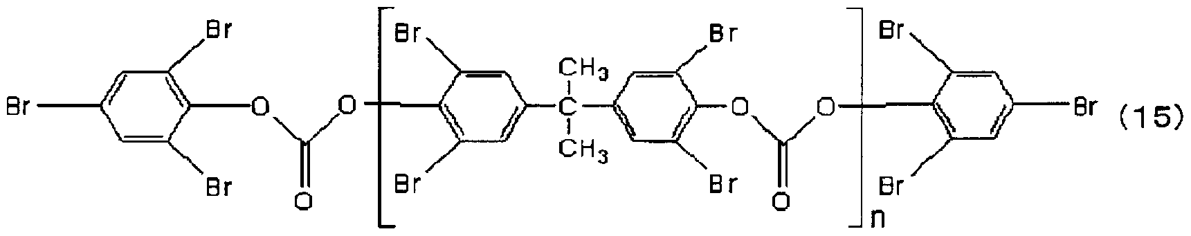


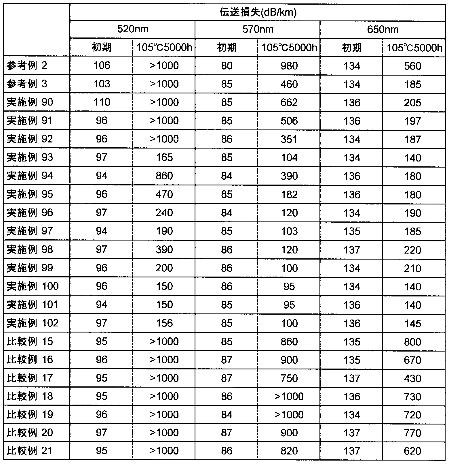
Claims
Priority Applications (5)
| Application Number | Priority Date | Filing Date | Title |
|---|---|---|---|
| KR1020097008613A KR101402462B1 (ko) | 2006-09-28 | 2007-09-28 | 플라스틱 광섬유 케이블 및 이를 이용한 신호 전송 방법 |
| US12/311,360 US8023789B2 (en) | 2006-09-28 | 2007-09-28 | Plastic optical fiber cable and method of signal transmission using the same |
| CN2007800357587A CN101517447B (zh) | 2006-09-28 | 2007-09-28 | 塑料光纤缆及使用该缆的信号传输方法 |
| EP07828800.8A EP2068184B1 (en) | 2006-09-28 | 2007-09-28 | Plastic optical fiber cable and signal transmission method with the same |
| JP2007550599A JP5236292B2 (ja) | 2006-09-28 | 2007-09-28 | プラスチック光ファイバケーブル及びこれを用いた信号伝送方法 |
Applications Claiming Priority (6)
| Application Number | Priority Date | Filing Date | Title |
|---|---|---|---|
| JP2006265773 | 2006-09-28 | ||
| JP2006-265773 | 2006-09-28 | ||
| JP2007-137855 | 2007-05-24 | ||
| JP2007137855 | 2007-05-24 | ||
| JP2007-183204 | 2007-07-12 | ||
| JP2007183204 | 2007-07-12 |
Publications (1)
| Publication Number | Publication Date |
|---|---|
| WO2008038791A1 true WO2008038791A1 (fr) | 2008-04-03 |
Family
ID=39230223
Family Applications (1)
| Application Number | Title | Priority Date | Filing Date |
|---|---|---|---|
| PCT/JP2007/069059 Ceased WO2008038791A1 (fr) | 2006-09-28 | 2007-09-28 | Câble à fibre optique en plastique et procédé de transmission de signaux utilisant celui-ci |
Country Status (6)
| Country | Link |
|---|---|
| US (1) | US8023789B2 (ja) |
| EP (1) | EP2068184B1 (ja) |
| JP (1) | JP5236292B2 (ja) |
| KR (1) | KR101402462B1 (ja) |
| CN (1) | CN101517447B (ja) |
| WO (1) | WO2008038791A1 (ja) |
Cited By (8)
| Publication number | Priority date | Publication date | Assignee | Title |
|---|---|---|---|---|
| JP2009237571A (ja) * | 2008-03-07 | 2009-10-15 | Mitsubishi Rayon Co Ltd | プラスチック光ファイバケーブル及び信号伝送方法 |
| WO2009157444A1 (ja) | 2008-06-23 | 2009-12-30 | 三菱レイヨン株式会社 | プラスチック光ファイバケーブル及び信号伝送方法 |
| JP2010002826A (ja) * | 2008-06-23 | 2010-01-07 | Mitsubishi Rayon Co Ltd | プラスチック光ファイバケーブル |
| JP2010033043A (ja) * | 2008-06-23 | 2010-02-12 | Mitsubishi Rayon Co Ltd | プラスチック光ファイバケーブル及び信号伝送方法 |
| JP2010186172A (ja) * | 2009-01-16 | 2010-08-26 | Mitsubishi Rayon Co Ltd | プラスチック光ファイバケーブル |
| JP2011209487A (ja) * | 2010-03-30 | 2011-10-20 | Toray Ind Inc | プラスチック光ファイバコード |
| WO2018168775A1 (ja) * | 2017-03-13 | 2018-09-20 | 三菱ケミカル株式会社 | プラスチック光ファイバ、プラスチック光ファイバケーブル、ワイヤーハーネス及び車両 |
| WO2023189998A1 (ja) * | 2022-03-31 | 2023-10-05 | 東レ株式会社 | プラスチック光ファイバおよび医療用センサ機器 |
Families Citing this family (17)
| Publication number | Priority date | Publication date | Assignee | Title |
|---|---|---|---|---|
| WO2010113639A1 (ja) * | 2009-03-31 | 2010-10-07 | 東レ株式会社 | プラスチック光ファイバおよびプラスチック光ファイバコード |
| US9842670B2 (en) * | 2013-11-08 | 2017-12-12 | Rockbestos Surprenant Cable Corp. | Cable having polymer with additive for increased linear pullout resistance |
| US8554039B2 (en) * | 2009-10-13 | 2013-10-08 | Corning Incorporated | Buffered large core fiber |
| CN102122050A (zh) * | 2010-10-13 | 2011-07-13 | 成都亨通光通信有限公司 | 耐热光缆 |
| CN103814319B (zh) * | 2011-09-14 | 2017-07-14 | 三菱化学株式会社 | 塑料光缆 |
| JP5982627B2 (ja) * | 2011-11-10 | 2016-08-31 | 本多通信工業株式会社 | 光通信モジュールの製造方法 |
| WO2013128956A1 (ja) * | 2012-02-27 | 2013-09-06 | 三菱電機株式会社 | 樹脂膜の劣化検出方法および樹脂膜の劣化検出装置 |
| TWM472295U (zh) * | 2013-05-09 | 2014-02-11 | Chun-Xing Wu | 抗干擾纜線 |
| ES2773285T3 (es) * | 2013-11-01 | 2020-07-10 | Toray Industries | Fibra óptica plástica de iluminación y procedimiento para fabricarla |
| US20200073019A1 (en) * | 2018-09-04 | 2020-03-05 | GM Global Technology Operations LLC | Protective film for a lens of a sensor |
| CN109870762B (zh) * | 2019-02-27 | 2020-11-03 | 南宁旭越光纤有限责任公司 | 一种低衰减塑料光纤及其制备方法 |
| CN109669234B (zh) * | 2019-02-27 | 2020-11-03 | 南宁旭越光纤有限责任公司 | 一种通体发光的导光条及其制备方法 |
| JP7281328B2 (ja) * | 2019-04-12 | 2023-05-25 | 日東電工株式会社 | プラスチック光ファイバーの製造方法 |
| CN110504061A (zh) * | 2019-05-30 | 2019-11-26 | 江苏亨通电子线缆科技有限公司 | 一种汽车用光电复合缆 |
| WO2021028034A1 (en) * | 2019-08-14 | 2021-02-18 | Synergia Medical | Polymer optical fibre for active implantable medical devices (aimd) and aimd using same |
| TW202120632A (zh) * | 2019-09-30 | 2021-06-01 | 日商日東電工股份有限公司 | 塑膠光纖 |
| US12449587B2 (en) | 2020-07-09 | 2025-10-21 | Toray Industries, Inc. | Plastic optical fiber, medical lighting device, medical sensor device, medical phototherapy device, and plastic optical fiber cord |
Citations (17)
| Publication number | Priority date | Publication date | Assignee | Title |
|---|---|---|---|---|
| JPH01273012A (ja) * | 1988-04-26 | 1989-10-31 | Mitsubishi Rayon Co Ltd | プラスチツク光フアイバ |
| JPH10319281A (ja) | 1997-05-16 | 1998-12-04 | Asahi Chem Ind Co Ltd | プラスチック光ファイバケーブル |
| JPH11242142A (ja) | 1998-02-24 | 1999-09-07 | Toray Ind Inc | 光ファイバ着色コード |
| JP2000231045A (ja) | 1999-02-08 | 2000-08-22 | Mitsubishi Rayon Co Ltd | プラスチック光ファイバケーブル |
| JP2001021737A (ja) | 1999-07-08 | 2001-01-26 | Asahi Chem Ind Co Ltd | 耐熱プラスチック光ファイバとその信号伝送方法 |
| JP2001074945A (ja) | 1999-09-08 | 2001-03-23 | Asahi Kasei Corp | 信号伝送用耐熱プラスチック光ファイバ及び該光ファイバを用いた信号伝送方法 |
| WO2001048526A1 (fr) | 1999-12-28 | 2001-07-05 | Mitsubishi Rayon Co., Ltd. | Cable a fibres optiques et cable a fibres optiques comportant un connecteur |
| JP2002055243A (ja) * | 2000-08-09 | 2002-02-20 | Mitsubishi Rayon Co Ltd | プラスチック光ファイバケーブル、プラグ付きプラスチック光ファイバケーブル、これらの固定方法および光伝送部品 |
| JP2002055246A (ja) * | 2000-08-10 | 2002-02-20 | Asahi Kasei Corp | 耐熱プラスチック光ファイバユニット |
| JP2003255202A (ja) | 2002-02-27 | 2003-09-10 | Mitsubishi Rayon Co Ltd | 光ファイバケーブルおよびプラグ付き光ファイバケーブル |
| JP2003315638A (ja) | 2002-04-18 | 2003-11-06 | Mitsubishi Rayon Co Ltd | 光ファイバケーブル、及びプラグ付き光ファイバケーブル |
| JP2004226925A (ja) | 2003-01-27 | 2004-08-12 | Mitsubishi Rayon Co Ltd | プラスチック光ファイバケーブルおよびプラグ付きプラスチック光ファイバケーブル |
| JP2005099447A (ja) * | 2003-09-25 | 2005-04-14 | Mitsubishi Rayon Co Ltd | プラスチック光ファイバケーブルの製造方法 |
| JP2005234135A (ja) * | 2004-02-18 | 2005-09-02 | Mitsubishi Rayon Co Ltd | プラスチック光ファイバ、及びプラスチック光ファイバケーブル |
| JP2006133488A (ja) * | 2004-11-05 | 2006-05-25 | Mitsubishi Rayon Co Ltd | プラスチック光ファイバケーブル |
| WO2006121048A1 (ja) * | 2005-05-09 | 2006-11-16 | Mitsubishi Rayon Co., Ltd. | プラスチック光ファイバケーブル |
| JP2007047424A (ja) * | 2005-08-09 | 2007-02-22 | Mitsubishi Rayon Co Ltd | プラスチック光ファイバケーブル |
Family Cites Families (5)
| Publication number | Priority date | Publication date | Assignee | Title |
|---|---|---|---|---|
| US7031582B2 (en) * | 1999-12-24 | 2006-04-18 | Mitsubishi Rayon Co., Ltd. | Optical fiber cable and optical fiber cable with plug |
| JP2003255201A (ja) * | 2002-02-27 | 2003-09-10 | Mitsubishi Rayon Co Ltd | 光ファイバケーブルおよびプラグ付き光ファイバケーブル |
| DE10228439A1 (de) * | 2002-06-26 | 2004-01-22 | Degussa Ag | Kunststoff-Lichtwellenleiter |
| JP4130456B2 (ja) | 2004-09-22 | 2008-08-06 | 株式会社東芝 | 半導体装置 |
| JP5207652B2 (ja) * | 2007-04-06 | 2013-06-12 | 三菱レイヨン株式会社 | プラスチック光ファイバケーブルの製造方法 |
-
2007
- 2007-09-28 US US12/311,360 patent/US8023789B2/en active Active
- 2007-09-28 CN CN2007800357587A patent/CN101517447B/zh active Active
- 2007-09-28 JP JP2007550599A patent/JP5236292B2/ja active Active
- 2007-09-28 KR KR1020097008613A patent/KR101402462B1/ko not_active Expired - Fee Related
- 2007-09-28 EP EP07828800.8A patent/EP2068184B1/en active Active
- 2007-09-28 WO PCT/JP2007/069059 patent/WO2008038791A1/ja not_active Ceased
Patent Citations (17)
| Publication number | Priority date | Publication date | Assignee | Title |
|---|---|---|---|---|
| JPH01273012A (ja) * | 1988-04-26 | 1989-10-31 | Mitsubishi Rayon Co Ltd | プラスチツク光フアイバ |
| JPH10319281A (ja) | 1997-05-16 | 1998-12-04 | Asahi Chem Ind Co Ltd | プラスチック光ファイバケーブル |
| JPH11242142A (ja) | 1998-02-24 | 1999-09-07 | Toray Ind Inc | 光ファイバ着色コード |
| JP2000231045A (ja) | 1999-02-08 | 2000-08-22 | Mitsubishi Rayon Co Ltd | プラスチック光ファイバケーブル |
| JP2001021737A (ja) | 1999-07-08 | 2001-01-26 | Asahi Chem Ind Co Ltd | 耐熱プラスチック光ファイバとその信号伝送方法 |
| JP2001074945A (ja) | 1999-09-08 | 2001-03-23 | Asahi Kasei Corp | 信号伝送用耐熱プラスチック光ファイバ及び該光ファイバを用いた信号伝送方法 |
| WO2001048526A1 (fr) | 1999-12-28 | 2001-07-05 | Mitsubishi Rayon Co., Ltd. | Cable a fibres optiques et cable a fibres optiques comportant un connecteur |
| JP2002055243A (ja) * | 2000-08-09 | 2002-02-20 | Mitsubishi Rayon Co Ltd | プラスチック光ファイバケーブル、プラグ付きプラスチック光ファイバケーブル、これらの固定方法および光伝送部品 |
| JP2002055246A (ja) * | 2000-08-10 | 2002-02-20 | Asahi Kasei Corp | 耐熱プラスチック光ファイバユニット |
| JP2003255202A (ja) | 2002-02-27 | 2003-09-10 | Mitsubishi Rayon Co Ltd | 光ファイバケーブルおよびプラグ付き光ファイバケーブル |
| JP2003315638A (ja) | 2002-04-18 | 2003-11-06 | Mitsubishi Rayon Co Ltd | 光ファイバケーブル、及びプラグ付き光ファイバケーブル |
| JP2004226925A (ja) | 2003-01-27 | 2004-08-12 | Mitsubishi Rayon Co Ltd | プラスチック光ファイバケーブルおよびプラグ付きプラスチック光ファイバケーブル |
| JP2005099447A (ja) * | 2003-09-25 | 2005-04-14 | Mitsubishi Rayon Co Ltd | プラスチック光ファイバケーブルの製造方法 |
| JP2005234135A (ja) * | 2004-02-18 | 2005-09-02 | Mitsubishi Rayon Co Ltd | プラスチック光ファイバ、及びプラスチック光ファイバケーブル |
| JP2006133488A (ja) * | 2004-11-05 | 2006-05-25 | Mitsubishi Rayon Co Ltd | プラスチック光ファイバケーブル |
| WO2006121048A1 (ja) * | 2005-05-09 | 2006-11-16 | Mitsubishi Rayon Co., Ltd. | プラスチック光ファイバケーブル |
| JP2007047424A (ja) * | 2005-08-09 | 2007-02-22 | Mitsubishi Rayon Co Ltd | プラスチック光ファイバケーブル |
Non-Patent Citations (3)
| Title |
|---|
| POLYMER, vol. 42, 2001, pages 10119 - 10132 |
| POLYMER, vol. 44, 2003, pages 6407 - 6417 |
| See also references of EP2068184A4 |
Cited By (19)
| Publication number | Priority date | Publication date | Assignee | Title |
|---|---|---|---|---|
| JP2009237571A (ja) * | 2008-03-07 | 2009-10-15 | Mitsubishi Rayon Co Ltd | プラスチック光ファイバケーブル及び信号伝送方法 |
| KR101593721B1 (ko) | 2008-06-23 | 2016-02-12 | 미츠비시 레이온 가부시키가이샤 | 플라스틱 광섬유 케이블 및 신호 전송 방법 |
| EP2306227A4 (en) * | 2008-06-23 | 2014-09-03 | Mitsubishi Rayon Co | FIBER OPTIC PLASTIC CABLE AND METHOD FOR TRANSMITTING A SIGNAL |
| JP2010033043A (ja) * | 2008-06-23 | 2010-02-12 | Mitsubishi Rayon Co Ltd | プラスチック光ファイバケーブル及び信号伝送方法 |
| WO2009157444A1 (ja) | 2008-06-23 | 2009-12-30 | 三菱レイヨン株式会社 | プラスチック光ファイバケーブル及び信号伝送方法 |
| KR20110022692A (ko) | 2008-06-23 | 2011-03-07 | 미츠비시 레이온 가부시키가이샤 | 플라스틱 광섬유 케이블 및 신호 전송 방법 |
| CN102132185A (zh) * | 2008-06-23 | 2011-07-20 | 三菱丽阳株式会社 | 塑料光纤缆及信号传输方法 |
| US8422844B2 (en) | 2008-06-23 | 2013-04-16 | Mitsubishi Rayon Co., Ltd. | Plastic optical fiber cable and method of transmitting signal |
| CN102132185B (zh) * | 2008-06-23 | 2013-03-06 | 三菱丽阳株式会社 | 塑料光纤缆及信号传输方法 |
| JP2010002826A (ja) * | 2008-06-23 | 2010-01-07 | Mitsubishi Rayon Co Ltd | プラスチック光ファイバケーブル |
| JP2014029555A (ja) * | 2009-01-16 | 2014-02-13 | Mitsubishi Rayon Co Ltd | 光ファイバケーブル |
| JP2010186172A (ja) * | 2009-01-16 | 2010-08-26 | Mitsubishi Rayon Co Ltd | プラスチック光ファイバケーブル |
| JP2011209487A (ja) * | 2010-03-30 | 2011-10-20 | Toray Ind Inc | プラスチック光ファイバコード |
| WO2018168775A1 (ja) * | 2017-03-13 | 2018-09-20 | 三菱ケミカル株式会社 | プラスチック光ファイバ、プラスチック光ファイバケーブル、ワイヤーハーネス及び車両 |
| US20200003932A1 (en) * | 2017-03-13 | 2020-01-02 | Mitsubishi Chemical Corporation | Plastic optical fiber, plastic optical fiber cable, wire harness and vehicle |
| JPWO2018168775A1 (ja) * | 2017-03-13 | 2020-01-09 | 三菱ケミカル株式会社 | プラスチック光ファイバ、プラスチック光ファイバケーブル、ワイヤーハーネス及び車両 |
| US10962685B2 (en) | 2017-03-13 | 2021-03-30 | Mitsubishi Chemical Corporation | Plastic optical fiber, plastic optical fiber cable, wire harness and vehicle |
| JP7279362B2 (ja) | 2017-03-13 | 2023-05-23 | 三菱ケミカル株式会社 | プラスチック光ファイバ、プラスチック光ファイバケーブル、ワイヤーハーネス及び車両 |
| WO2023189998A1 (ja) * | 2022-03-31 | 2023-10-05 | 東レ株式会社 | プラスチック光ファイバおよび医療用センサ機器 |
Also Published As
| Publication number | Publication date |
|---|---|
| CN101517447B (zh) | 2011-05-18 |
| KR20090065541A (ko) | 2009-06-22 |
| JP5236292B2 (ja) | 2013-07-17 |
| CN101517447A (zh) | 2009-08-26 |
| EP2068184B1 (en) | 2013-09-25 |
| US8023789B2 (en) | 2011-09-20 |
| JPWO2008038791A1 (ja) | 2010-01-28 |
| EP2068184A1 (en) | 2009-06-10 |
| KR101402462B1 (ko) | 2014-06-03 |
| US20090279837A1 (en) | 2009-11-12 |
| EP2068184A4 (en) | 2012-03-28 |
Similar Documents
| Publication | Publication Date | Title |
|---|---|---|
| WO2008038791A1 (fr) | Câble à fibre optique en plastique et procédé de transmission de signaux utilisant celui-ci | |
| CN102132185B (zh) | 塑料光纤缆及信号传输方法 | |
| TWI458741B (zh) | 塑膠光纖及塑膠光纖軟線 | |
| KR101016082B1 (ko) | 플라스틱 광섬유 케이블 | |
| JP5394140B2 (ja) | プラスチック光ファイバケーブル及び信号伝送方法 | |
| JP2009237571A (ja) | プラスチック光ファイバケーブル及び信号伝送方法 | |
| CN100538420C (zh) | 塑料光纤电缆 | |
| JP5430086B2 (ja) | プラスチック光ファイバケーブル | |
| JP4663444B2 (ja) | プラスチック光ファイバケーブル | |
| JP5459070B2 (ja) | プラスチック光ファイバおよびプラスチック光ファイバコード | |
| JP2003139973A (ja) | プラスチック光ファイバ、プラスチック光ファイバケーブル及びプラグ付きプラスチック光ファイバケーブル | |
| JP4225547B2 (ja) | プラスチック光ファイバ、及びプラスチック光ファイバケーブル | |
| JP2005266742A (ja) | プラスチック光ファイバケーブルおよびその製造方法 | |
| JP2006133488A (ja) | プラスチック光ファイバケーブル | |
| JP2007047371A (ja) | プラスチック光ファイバケーブルの製造方法 | |
| JP2007047258A (ja) | プラスチック光ファイバケーブル | |
| JP2010079273A (ja) | プラスチック光ファイバコード |
Legal Events
| Date | Code | Title | Description |
|---|---|---|---|
| WWE | Wipo information: entry into national phase |
Ref document number: 200780035758.7 Country of ref document: CN |
|
| ENP | Entry into the national phase |
Ref document number: 2007550599 Country of ref document: JP Kind code of ref document: A |
|
| 121 | Ep: the epo has been informed by wipo that ep was designated in this application |
Ref document number: 07828800 Country of ref document: EP Kind code of ref document: A1 |
|
| WWE | Wipo information: entry into national phase |
Ref document number: 12311360 Country of ref document: US |
|
| NENP | Non-entry into the national phase |
Ref country code: DE |
|
| WWE | Wipo information: entry into national phase |
Ref document number: 2007828800 Country of ref document: EP |
|
| WWE | Wipo information: entry into national phase |
Ref document number: 1583/KOLNP/2009 Country of ref document: IN Ref document number: 1020097008613 Country of ref document: KR |