WO2009057367A1 - 気泡安定液の調整方法と気泡掘削施工法 - Google Patents
気泡安定液の調整方法と気泡掘削施工法 Download PDFInfo
- Publication number
- WO2009057367A1 WO2009057367A1 PCT/JP2008/064571 JP2008064571W WO2009057367A1 WO 2009057367 A1 WO2009057367 A1 WO 2009057367A1 JP 2008064571 W JP2008064571 W JP 2008064571W WO 2009057367 A1 WO2009057367 A1 WO 2009057367A1
- Authority
- WO
- WIPO (PCT)
- Prior art keywords
- bubble
- stabilizer
- water
- water content
- soil
- Prior art date
- Legal status (The legal status is an assumption and is not a legal conclusion. Google has not performed a legal analysis and makes no representation as to the accuracy of the status listed.)
- Ceased
Links
Classifications
-
- E—FIXED CONSTRUCTIONS
- E21—EARTH OR ROCK DRILLING; MINING
- E21D—SHAFTS; TUNNELS; GALLERIES; LARGE UNDERGROUND CHAMBERS
- E21D9/00—Tunnels or galleries, with or without linings; Methods or apparatus for making thereof; Layout of tunnels or galleries
-
- C—CHEMISTRY; METALLURGY
- C09—DYES; PAINTS; POLISHES; NATURAL RESINS; ADHESIVES; COMPOSITIONS NOT OTHERWISE PROVIDED FOR; APPLICATIONS OF MATERIALS NOT OTHERWISE PROVIDED FOR
- C09K—MATERIALS FOR MISCELLANEOUS APPLICATIONS, NOT PROVIDED FOR ELSEWHERE
- C09K8/00—Compositions for drilling of boreholes or wells; Compositions for treating boreholes or wells, e.g. for completion or for remedial operations
- C09K8/02—Well-drilling compositions
- C09K8/38—Gaseous or foamed well-drilling compositions
-
- E—FIXED CONSTRUCTIONS
- E21—EARTH OR ROCK DRILLING; MINING
- E21D—SHAFTS; TUNNELS; GALLERIES; LARGE UNDERGROUND CHAMBERS
- E21D9/00—Tunnels or galleries, with or without linings; Methods or apparatus for making thereof; Layout of tunnels or galleries
- E21D9/06—Making by using a driving shield, i.e. advanced by pushing means bearing against the already placed lining
- E21D9/0642—Making by using a driving shield, i.e. advanced by pushing means bearing against the already placed lining the shield having means for additional processing at the front end
- E21D9/0678—Adding additives, e.g. chemical compositions, to the slurry or the cuttings
- E21D9/0685—Foaming agents
Definitions
- the present invention relates to a method for adjusting a bubble stabilizing liquid for excavating by mixing bubbles and water or cement milk into ground excavation soil, and a bubble excavation construction method based on the method.
- the underground continuous wall construction method was adopted as a construction method for earth retaining walls and water barriers in Europe around 1950 and was first introduced in Japan as a water barrier for river cut-offs in 1959. Later, in construction work around the urban area, noise, vibration, subsidence of the surrounding ground and the effect on the groundwater level, etc., caused when steel sheet piles and existing piles were placed became social problems. It is adopted as a construction method. In recent years, it has been adopted not only for deepening and increasing the size, but also for temporary structures to permanent structures. In addition to concrete structures, the use as soil cement underground wall structures is expanding.
- bentonite dredging system stabilizer is used to maintain the stability of the trench wall and facilitate the drainage of excavated soil.
- this method has a large amount of mud soil, and it is difficult to reuse the waste mud soil mixed with bentonite and the treatment cost is high, so an alternative is required.
- a suspension of 15 to 40% air bubbles and appropriate amount of water added to the excavated earth and sand has various functions as a stabilizer.
- the underground continuous wall construction method using a stabilizer is It is known that it will not change in the future.
- this suspension stabilizes the groove wall and becomes a bubble stabilizer with fluidity and other functions.
- Continuous excavation is possible. Air bubbles in the mud soil and sand are left in the air or added with an antifoaming agent so that they are easily removed. For this reason, the amount of mud is reduced to 1/2 or less compared to the bentonite stabilizer, so it can be said that the foam stabilizer is excellent in environmental load and economy.
- the bubble shield method is a method that uses bubbles as a mud material in the earth pressure shield method.
- the addition of bubbles increases the fluidity and water-stopping properties of the excavated sediment in the chamber and the screw conveyor, and the viscous soil. It is intended to prevent the adhesion of.
- the bubbles in the mud soil are defoamed by natural defoaming or defoaming agent, the mud soil returns to the state before the bubble injection, and post-treatment is easy.
- the mechanism that resists shield face pressure due to the earth pressure in the chamber containing bubbles has been conceptually shown, no detailed study has been conducted on the face ground stabilization mechanism by the bubbles themselves.
- the bubble stabilization liquid is directly involved in the stability of the excavation groove wall in the same way as the bentonite type stabilization liquid. It is necessary to examine in detail the stabilization mechanism and performance.
- the main material of the bubble stabilizer is bubbles, there is a significant difference in the function mechanism of the groove wall stability and fluidity from the bentonite stabilizer.
- large differences occur in the amount of sludge and treatment costs.
- the foam stabilization liquid was devised based on the above-mentioned existing knowledge and technology. “It is a homogeneous suspension of excavated sediment, bubbles and water, and the stability of the groove wall, It can be defined as a “stable liquid excellent in fluidity”. However, the physical properties of the foam stabilization liquid are strongly influenced not only by the amount of added bubbles and water, but also by the particle size of the excavated sediment and consistency characteristics. Therefore, when subsurface excavation using bubble stabilizer, appropriate control indicators such as the specific gravity and funnel viscosity of bentonite stabilizer can be established, and the effect can be evaluated. It is necessary to carry out excavation management while making adjustments.
- Non-Patent Document 1 Shield Technology Association “Bubble Shield Method” (Jun. 1999)
- Patent Document 1 Japanese Patent No. 3 1 2 4 3 6 8
- Patent Document 2 Japanese Patent No. 2 7 6 8 10 04
- Patent Document 3 Japanese Patent No. 3 7 2 5 7 50
- the present invention eliminates the conventional problems and makes clear the management index on the excavation construction of the bubble stabilizing liquid, and the preparation method of the bubble stabilizing liquid based on this and the ground
- the challenge is to provide new methods for drilling. Disclosure of the invention
- the present invention is characterized by the following in order to solve the above problems.
- Wmin Defoaming water content ratio
- the defoaming water content Wmin is determined based on the sum of the surface dry water content of the coarse particles contained in the excavated soil and the shrinkage limit water content of the fine particles. 4. The method for adjusting a bubble stabilizing liquid according to any one of the third.
- Separation moisture content Wsep is the sum of the separation moisture content of the coarse particles contained in the excavated soil and the separation moisture content of the fine particles.
- the separation water content of the coarse particles is a linear function of the specific surface area of the coarse particles and the bubble addition rate of the bubble stabilizer.
- the TF value is the water content ratio W, air bubbles for each of the 4 regions where the fine grain content P of the excavated soil is 10% or more or less than 10%, and the bubble addition rate is 1% or more or less than 1%. It is managed as a function of the addition rate Q, the specific surface area S of the coarse portion of the excavated soil, the fine particle content P of the excavated soil, and the liquid limit W L of the fine portion of the excavated soil. Or the method for preparing a bubble stabilizing solution according to any one of 5 to 5.
- the minimum bubble addition rate (Q min) is determined as an index indicating the amount of bubbles necessary to keep the TF value above the control value when the water content ratio W is the defoaming water content ratio (Wmin). 7. The method for preparing a bubble stabilizing liquid according to any one of the first to sixth features.
- Stabilized liquid unit volume weight c, bubble addition rate Q, fine particle content P, stabilizer water content ratio W, coarse volume soil particle unit volume weight ss, fine particle content Soil particle unit volume weight r sc, water unit volume weight rw, and bubble unit volume weight rb are managed as a function of the maximum bubble addition amount (Q max), which is necessary to keep a c above the control value.
- Q max maximum bubble addition amount
- No. 10 A bubble drilling method characterized in that the ground is excavated by adjusting the bubble stabilizing liquid by the method described in any one of the above first to ninth.
- Item 1 The method of excavating a bubble according to item 11 above, wherein when the bubble stabilizing liquid is solidified, an antifoaming material is mixed and solidified in the solidified material in order to increase the strength of the solidified body.
- No. 13 The shield construction method, in which the bubble stabilizer is filled between the cut face and face of the shield propulsion unit and inside the face, and excavation is performed while preventing the face from collapsing.
- FIG. 1 is a process diagram illustrating a method for producing a bubble stabilizing liquid.
- Fig. 2 is a schematic diagram showing the water content of aggregate soil particles.
- Fig. 3 is a schematic diagram of a cylindrical separation water content measuring device used in the separation experiment.
- Figure 4 shows the effect of the specific surface area contained in the excavated earth and sand by preparing a bubble stabilization liquid with a certain amount of foam addition of 2% for each type of silica sand in Table 1 and changing the water content ratio.
- Figure 5 shows the results of comparing the measured values of the separated water content with the estimated values based on Eq. (8) for each factor.
- Fig. 6 is a diagram of the experimental equipment used for experiments according to the variable-level water permeability test.
- Figure 7 shows the results of investigating the relationship between the amount of water permeation and time in the bubble stabilizer and bentonite stabilizer.
- Figure 8 shows the results of investigating the relationship between the amount of water permeation and time in the bubble stabilizer and bentonite stabilizer.
- Fig. 9 shows a case where the groove wall is collapsed by gradually increasing the groundwater pressure inside the simulated ground against the groove wall where the impermeable layer is formed with the stable liquid and kept stable by the hydraulic pressure.
- the relationship between stable hydraulic pressure and water pressure It is the experimental apparatus figure used in order to investigate.
- Toyoura sand as simulated ground and using bubble stabilizer and bentonite stabilizer. 4 is an experimental result when a k N Roh m 2.
- Toyoura sand as simulated ground and using bubble stabilizer and bentonite stabilizer. It is an experimental result when it is set to 4 k NZm 2 .
- Figure 12 shows the ratio between the pore water pressure in the ground and the stable hydraulic pressure based on Table 6 showing the experimental results when the wall collapses.
- Figure 13 shows the relationship between the TF value and water content when a) the bubble addition rate, b) the specific surface area, c) the fine particle content, and d) the liquid limit is a parameter. It is.
- Fig. 14 shows the result of redrawing Fig. 13-a) with the water content ratio as a parameter prior to determining,) 3.
- Fig. 15 shows the results of redrawing Fig. 13-c) with the water content ratio as a parameter prior to determining,) S.
- Figure 16 shows the results of comparing the estimated T F values obtained by Equation (10) and the measured T F values by region.
- Fig. 17 is an example of the bubble stabilizer control chart.
- Figure 18 shows the control chart of the stabilizer used in the construction and the measured values of the unit volume weight and TF value of the foam stabilizer during construction.
- Figure 19 shows the control chart of the bubble stabilizer used at the site and the measured unit volume weight and TF value of the foam stabilizer during construction.
- the bubble stabilizing liquid of the present invention is formed continuously by adding bubbles and water or cement milk to the excavated soil and mixing and kneading, and has a stable effect as a homogeneous suspension in excavation construction. Is.
- Wmin Defoaming water content
- the curves of the indicators W min, W sep, Q min, and Q max are used. It is characterized by adjusting the amount of bubbles and the amount of water or cement milk so that it is within the enclosed range.
- foaming agents such as alkyl sulfate surfactants, partially hydrolyzed proteins, alkyl ether compound complexes, etc. Can be considered. Above all, in order to obtain the performance to keep the groove wall, which is most required as a function of the stabilizer, in a stable state, it is difficult to defoam, it has excellent chemical stability such as acid and alkali, and foaming ability It is preferable to use an alkyl sulfate surfactant as a large foaming agent.
- the foaming agent used in the following verification is a product used for cellular concrete, air mortar, etc. If the bubble size obtained is in the range of about 20 to 500 m, it can be used in the same manner as the following verification.
- the soil samples for testing as simulated soil are Touraura sand, silica sand No. 6, silica sand No. 5, quartz sand No. 4, silica sand No. 3, NS 30 as coarse-grained soil, kaolin with different consistency characteristics
- a coarse-grained soil and a fine-grained soil were mixed as appropriate to prepare a sample.
- the sample was marked with a symbol as shown in Table 1.
- Coarse soils of coarse and fine soils are described with a hyphen as shown in To-Ka.
- D 5 Is the 50% particle size of the sample, S is the specific surface area, liquid limit, and I p is the plasticity index.
- the bubble stabilizer is first verified for the case of adding bubbles and water to the excavated soil.
- the use of cement milk instead of water will be explained later.
- the foam stabilizing solution is prepared by diluting the foaming agent stock solution 20 times with water according to the specifications, and then foaming it with a hand mixer to a volume of 25 times. Create bubbles, add the bubbles and water to the sample soil, and mix so that the sample soil, bubbles and water are evenly dispersed.
- the dilution ratio of this foaming agent is the dilution factor specified in the foaming agent specifications. If the specifications use different foaming agent employs a dilution ratio can be maximized functionality of a foaming agent, by adjusting the specific weight T b of the bubble below the air foam addition ratio Q
- the bubble addition rate Q to the bubble stabilizer can be defined by equation (1). it can. As is clear from equation (1), the bubble addition rate Q is defined as the ratio of the bubble weight to the dry weight of the excavated soil. The amount of bubbles added is the weight of bubbles added to the dry weight of the excavated soil.
- the suspension will remain in a stable state.However, when the excavated soil is in a dry state, the water in the bubbles is absorbed by the water absorption of the soil particles. Defoaming occurs. On the contrary, when the water content is high and the water content is high, the soil particles are separated and settled, and the bubble stabilizer becomes inhomogeneous.
- the minimum moisture content at which bubbles do not defoam is defined as the defoamed moisture content
- the moisture content at which soil particles cause separation / sedimentation is defined as the separation moisture content.
- the soil particles here refer to all the coarse particles and fine particles in the excavated soil.
- the minimum water content that does not cause defoaming in the bubble stabilizer is the defoaming water content (W fflin).
- W fflin defoaming water content
- the defoaming moisture content of coarse particles was evaluated by paying attention to the moisture content of the surface dry state used during the concrete aggregate design.
- the moisture content of aggregate soil particles is divided into four levels as shown in Fig. 2. It is considered that the defoaming phenomenon occurs when the soil particles adsorb bubbles in this case, when the moisture content is lower than the surface dry state. Therefore, in the case of coarse particles, the defoaming water content ratio can be the water content ratio corresponding to the surface dry state (surface dry water content ratio).
- the fine particles shrink through the steps of normal shrinkage, residual shrinkage, and no shrinkage due to a decrease in the water content.
- the soil particle skeleton volume does not change, and only the pore liquid volume appears. Therefore, it is considered that fine particles adsorb bubbles and eliminate bubbles below the water content ratio corresponding to the shrinkage limit at which residual shrinkage stops. Therefore, in the case of fine particles, a water content ratio corresponding to the shrinkage limit (shrinkage limit water content ratio) can be adopted as the defoaming water content ratio.
- the defoaming moisture content corresponding to the excavated soil is determined in consideration of the influence of coarse and fine particles contained in the above bubble stabilizer on the defoaming conditions. If the bubbles are not adsorbed by the soil particles and do not defoam, the excavated soil composed of coarse and fine particles will have at least a water volume and fineness corresponding to the surface dryness of the coarse particles. There must be an amount of water corresponding to the shrinkage limit of the grain. Considering the contribution of fine and coarse particles, the sum of the water content is expressed in the form of the moisture content of all soils.
- the defoaming moisture content (Wmin) of the excavated soil is expressed by the following equation (2). Defined.
- Wmin is the defoaming water content ratio (%)
- P is the fine grain content (%).
- Table 2 shows the shrinkage limit moisture content of general soil composed of fine grains.
- Factors affecting the water content of the separation include the water content ratio W of the foam stabilization liquid, the foam addition rate Q, the specific surface area of the coarse portion of the excavated soil (hereinafter referred to as the specific surface area) S, the fine particle content P, and the liquidity Focusing on the limits, we can confirm these effects through experiments and obtain an estimation formula for the separation water content.
- a bubble stabilizing solution was prepared by changing the water content ratio to a certain amount of 2% for each type of silica sand in Table 1.
- Figure 4 shows the results of the weight ratio.
- S represents the specific surface area (m 2 kN) of each sample.
- Fig. 4 it can be seen that the weight ratio rises abruptly when the weight ratio is about 1, 0 2 or more for any sample, and the bubble stabilizer is separated. Therefore, the water content corresponding to the weight ratio of 1.0 to 2 was found on the diagram and used as the separation water content (Wsep).
- the separation water content is 31.0%
- silica sand 6 is 25.0%
- silica sand 5 is 16.5%
- silica sand 4 is 11.5%
- silica sand 3 6 It was found that the specific surface area of the soil particles and the water content of the separation were proportional. This is because of the adhesion between soil particles and bubbles, the larger the specific surface area, the larger the bubbles. It can be considered that it is influenced by the buoyancy of.
- the specific surface area was determined by the formula (5) using the 50% particle size of the coarse particles.
- S is the specific surface area of the coarse particles (m 2 / k N)
- D s 50 is the 50% particle size of the coarse particles (m)
- rs is the unit volume of the coarse particles Weight (k N / m 3 ).
- Wsep2 W L (7) where Wsep2 is the separation water content (%) of fine particles and W L is the liquid limit (%).
- the separation water content of the bubble stabilizer can also be expressed by the equation (8) when the sum of the water content corresponding to the separation water content of the coarse and fine particles is the same as the minimum water content. It becomes.
- the impermeable layer formed on the groove wall by the excavating stable liquid plays an important role in preventing the collapse of the groove wall by preventing water flow and transferring the hydraulic pressure to the groove wall.
- the bentonite mud film formed on the groove wall serves as an impermeable layer.
- bubble stabilization liquid bubbles enter the gaps in the surrounding raw ground and form an impermeable layer that is several times thicker than the bentonite mud film, integrated with the unsaturated soil particle skeleton. It is envisaged to form.
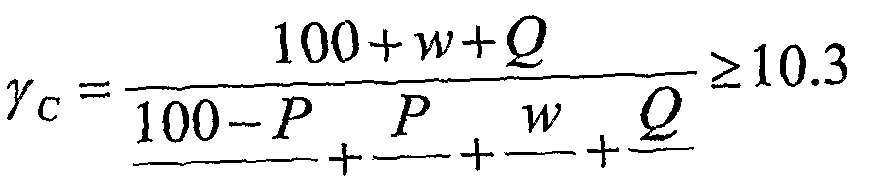
- the unit volume weight c of the foam stabilizer composed of soil particles (coarse and fine), bubbles, and pore water of the excavated soil can be expressed by equation (9).
- the unit volume weight of the stabilizer required to maintain the stability of the groove wall is 10.3 (k NZm 3 ) or more corresponding to the minimum specific gravity 1.05 in the bentonite stabilizer control chart. can do.
- Eq. (9) the inequality to be satisfied by the bubble addition rate Q and the water content ratio w is determined for the bubble stabilizer using a specific excavated soil.
- the bubbles stabilizing solution the bubble added assuming actual drilling situation to each sample of saturated, was adjusted to a target of r c by changing the air foam addition amount.
- the bubble stabilizer has the ability to form an impermeable layer in a shorter time than the bentonite stabilizer and can be applied to a formation containing coarser gravel.
- permeability apparent is 1 0-5 (c / s) order
- the water permeability coefficient is 1 0- 6 (c / s) order, the original 3 or more digits smaller than the permeability coefficient of the ground.
- the sample soil used was Toyoura sand and quartz sand No. 5 and quartz sand No. 4, which are relatively difficult to form an impermeable layer with a stabilizing solution.
- the stabilizer used was the same as that prepared in the previous section.
- the water pressure in the simulated ground was measured by installing five pore water pressure gauges between 5 and 25 cm from the groove wall.
- the sample soil was put into a simulated ground soil tank and compacted well to reach saturation. At the top of the jack was added over No ⁇ (9. 8 ⁇ 2 9. 4 k N / m 2) in the simulated soil upper surface. Put the stabilizer in the stabilizer cylinder and place it in the cylinder. Air pressure corresponding to the fixed liquid pressure plus (1 9. 6 ⁇ 3 9. 2 k N / m 2).
- the partition plate separating the stabilizer and the simulated ground was slowly pulled out over a sufficient time of 5 minutes or more so that an impermeable layer was formed.
- pressurized water was supplied from the water cylinder for water supply into the simulated ground.
- the pressurized water pressure was increased at a rate of 9. S k NZm 2 in 3 minutes.
- the average value of the measured pore water pressure in the simulated ground does not rise even after 3 minutes after pressurization, or the collapse of the groove wall was confirmed by visual inspection. .
- the pore water pressure in the simulated ground monotonously increases within the range where the pressurized water pressure does not exceed the stable hydraulic pressure, but the interstitial water pressure is stable when the pressurized water pressure exceeds the stable hydraulic pressure.
- the peak no longer increases at a peak of 4 8 0 4 k N / m 2 8.8 4 k NZm 2 higher than the hydraulic pressure. This is a state in which pore water in the simulated ground flows into the stable liquid due to pressurized water, which means the collapse of the groove wall.
- the permeability coefficient of the mud membrane is sufficiently small, so that the pore water pressure in the ground is almost equivalent to the pressurized water pressure in the range where the pressurized water pressure is smaller than the stable fluid pressure. .
- the pore water pressure in the ground does not increase at about 48 k NZm 2 as in the case of the bubble stabilizer, so it can be judged that the groove wall has collapsed.
- Silica Sand No. 5 and Silica Sand No. 4 were used, an impermeable layer could be formed with the bubble stabilizer, but an impermeable layer could not be formed with the bentonite stabilizer. The wall collapsed.
- Figure 12 shows the ratio of pore water pressure and stable hydraulic pressure in the ground based on Table 6 which shows the experimental results when the wall collapses.
- the ratio of the collapsed water pressure to the stable fluid pressure is distributed in the range of 1.1 to 1.5 regardless of the stable fluid pressure for both the bubble stabilizer and the bentonite stabilizer, and the bubble stabilizer is equivalent to the bentonite stabilizer. It can be said that it has performance.
- the legend a in the figure is the bubble stabilizer and be is the bentonite stabilizer.
- Channel viscosity and table flow value are used as indicators of fluidity related to the drilling performance of the bubble stabilizer.
- the funnel viscosity used in the bentonite-based stabilizer is an index that represents the viscosity of the stabilizer alone, whereas the TF value can represent a wider range of fluidity including excavated sediment.
- Factors affecting the T F value include water content ratio, bubble addition rate, specific surface area of excavated soil, fine grain content rate, and liquid limit. Therefore, the relationship between the TF value and the water content ratio was examined using the bubble addition rate, specific surface area, fine particle content, and liquid limit as parameters.
- Fig. 14 ⁇ prior to the determination of Fig. 13 — a) and c) with the water content as a parameter, respectively, are redrawn as shown in Fig. 14 and Fig. 15 respectively.
- Fig. 14 From Fig. 14 it can be seen that when the bubble addition rate is between 0 and 1%, the TF value increases rapidly as the amount of bubbles increases and is proportional. However, when the bubble addition rate exceeds 1%, the TF value does not change even if the amount of bubble addition increases, but rather a slight downward trend is observed. This is thought to be because bubbles enter between the soil particles to reduce the frictional force up to 1%, but the contact between the soil particles is lost when it exceeds 1%.
- the TF value tends to increase when the kaolin content is in the range of 0 to 10%, but decreases when it exceeds 10%. This is because it works as a lubricant when the amount of fine particles is small (less than 10%), but when it exceeds 10%, the fluidity inhibition effect due to increased viscosity is greater than the lubrication effect. It is done. Based on these facts, in determining ⁇ ,) 8, there are four regions where the fine particle content ⁇ is 10% or less, and the bubble addition rate Q is 1% or less. Thus, the coefficients CB n and j8 n were determined individually.
- Fig. 16 shows a comparison of the estimated T F values and actual measured T F values obtained as described above for each region. From this, it can be judged that the TF value can be estimated using the above equation when the practically meaningful TF value is in the range of 100 (mm) to 300 (mm).
- r c and TF values are both physical properties of the excavated soil (p, s, w L, r ss, r sc) water and bubbles unit weight ( ⁇ w, r b) of the given, foam stabilizer Is a function of two variables: the bubble addition rate Q and the water content w. Therefore, the limit values of Q and w were determined according to the following procedure, and a control chart of the bubble stabilizer was created based on the c and TF values.
- the fluidity of the bubble stabilization liquid which controls the drilling performance, is controlled by a TRD method with a TF value of 150 to 200 mm.
- TF n a n w + ⁇ ⁇ > ⁇ 5 ⁇ (1 1)
- TF n TF value of region ⁇ , ⁇ ⁇ , j8 n : Estimates for each region n in Table 7.
- a n , j8 Substitute physical properties of excavated soil into ⁇ ⁇ ⁇ always takes a positive value, and ⁇ ⁇ , / 3 ⁇ is a linear expression of the bubble addition rate Q. Therefore, the establishment of the equality in this inequality is when the water content ratio w of the bubble stabilizer is the minimum water content ratio Wmin, and it is necessary to keep it above the bubble addition rate calculated by substituting Wmin. If this bubble addition rate is the minimum bubble addition rate Qmin, the control limit for keeping the TF value above the specified control value is the minimum bubble addition rate Qmin.
- the water content of the bubble stabilizer must be greater than the minimum water content (W min), which represents the defoaming limit of bubbles, and must be kept below the separation water content (Wsep), which is the separation limit. Is represented by the formula (1 2).
- W in and Wsep are expressed by Eqs. (3) and (8), substituting the physical properties of excavated sediment (P, S, W L ) into these values makes Wmin a constant, and Wsep is the first order of Q It becomes an expression.
- the separation water content Wsep is the minimum water content at which separation of the soil particles occurs, so Wsep can be calculated by substituting Qmin as the Q value. Therefore, Wmin and Wsep, which are control limit values related to the suspension stability of the bubble stabilizer, are determined.
- control limit values are calculated by substituting the physical properties of the excavated soil into Equation (3), Equation (11), Equation (8), and Equation (13). Then Wmin can be calculated from equation (3). Qmin is obtained by substituting into Eq. (1 1), and this is substituted into Eq. (8) to obtain Wsep, which is substituted into Eq. (1 2) to obtain Qraax
- bentonite stabilizer uses the relationship diagram between the specific gravity of the bentonite stabilizer and the funnel viscosity, and in accordance with this, the control limit is shown in the relationship diagram between the unit volume weight r c of the bubble stabilizer and the TF value.
- the bubble stabilization liquid control chart that plots the minimum water content Wmin, separation water content Wsep, maximum bubble addition rate Qmax, and minimum addition rate Qmin, it is possible to easily manage and adjust the bubble stabilization solution. Become.
- An example of the control chart for the bubble stabilizer is shown in Figure 17.
- the unit volume weight c (formula (9)) and TF value (formula (10) and table 7) of the bubble stabilizer are functions with Q and W as one parameter.
- the water content ratio is a constant value
- Q a constant value
- equal air foam addition ratio lines and connecting these are obtained.
- the area enclosed by the water content ratio, the minimum water content Wmin of the isobubble content diagram, the separation water content ratio Wsep, the maximum air content rate Qmax, and the minimum content rate Qmin is This is an area where stable excavation with a stable liquid is possible.
- the method of adjusting the bubble stabilizer using the bubble stabilizer control chart shown in Fig. 17 can be summarized as follows.
- ⁇ 1> Stable construction is possible when the unit volume weight and TF value of the bubble stabilizer are in the range of A.
- ⁇ 2> In the region B, the unit volume weight of the bubble stabilizer is small, There is a risk of collapse of the groove wall. When the state of the bubble stabilizer approaches the boundary between A and B, the amount of bubbles added is decreased and the unit volume weight is increased.
- ⁇ 4> In the D region, the T F value decreases rapidly, and the fluidity is impaired. Therefore, when the boundary between A and D is approached, the amount of bubbles added is increased.
- adjustment and control of the bubble stabilizer during excavation can be achieved by combining the amount of bubble added and the amount of water added.
- Cement milk is basically a mixture of cement and water.
- the cement milk can have a water-cement ratio (Ww c ZW c ) of a desired value in the range of 0.6 to 4.0, and the usage range is as follows. It is exemplified to be 5 0 to 4 0 0 k / m 3 .
- Table 8 shows the correlation between the symbol (W) used when the foam stabilizer is composed of excavated soil, bubbles, and water, and the symbol used when the water is replaced with cement milk (C).
- Table 9 shows the symbols used in the calculation.
- Liquid limit of excavated soil Liquid limit is measured with a predetermined amount of water w L w LC
- the liquid limit when using cement milk can use the value measured by mixing an appropriate amount of cement with the fine particles of soil particles.
- the unit volume weight of the foam stabilizer is expressed by the above formula (9), the unit volume weight ee when using cement milk includes the weight of cement milk and the weight of water. 2 3) Ru
- r d is the dry density (kN / m 3 ) of the soil particles, and is known, so it can be obtained by substituting the water-cement ratio X of cement milk and the cement addition amount y.
- the minimum water content when using cement milk should be expressed by the following formula (24) by using P c instead of P. Can do.
- control value limit can be expressed by the following formulas (28) to (30). [Number 2 8]
- the bubble excavation construction method of the invention of this application is characterized in that the bubble stabilizing liquid is adjusted based on the above-described method for adjusting the bubble stabilizing liquid, and the ground is excavated.
- Typical examples of such bubble excavation work include a continuous underground wall construction method that prevents clogging of the ditch walls and facilitates drainage, and shields.
- Examples of the shield method include drilling while filling the bubble stabilizer liquid between the force terface and the face of the propulsion device and in the chamber, and preventing the face from collapsing, etc.
- the invention is not limited to this.
- the bubble stabilizer when the bubble stabilizer is solidified on site, it can be considered to mix an antifoaming material in the solidified material and solidify it in order to increase the strength of the solidified body.
- Example 1 Construction of continuous soil cement wall with foam stabilizing liquid Based on the results of construction of continuous cement wall with strong weathered tuff and Tenman gravel layer using foam stabilizing liquid with TRD excavator in the previous chapter The validity of the on-site management method of the bubble stabilizer was devised.
- Construction method Soil cement underground continuous wall by TRD method.
- Embankment 0 to l m, volcanic ash silt; l to 3 m, from strongly weathered surface
- Ashstone (loam and mixed with gravel); 3-16m, weathered sedimentary structure
- Soil particle unit volume weight of coarse and fine particles physical properties
- the amount of water added 0. 2 9 0 m 3 (in the second E-ku 0. 3 5 0 m 3).
- Fig. 18 plots the control chart of the stabilizer used in the construction and the range of measured values of unit volume weight and TF value of the foam stabilizer during construction.
- the unit volume weight of the aerated weaker fixed liquid is 1 1. 8 ⁇ 1 2. 8 k N / m 3, TF value It was stable from 1 85 to 200 mm.
- Table 12 shows the amount of soil excavated, the amount of bubbles added, the amount of water added, and the amount of mud soil during excavation. It is presumed that the amount of waste mud is less than the amount of bubbles and water added because the bubbles were defoamed during the construction of the sill cement wall and that the bubble stabilizer was permeated through the groove wall. Using the formula (3 1), the drainage rate for excavation is 28.6%, and the bentonite stabilizer is used for the same soil quality. Compared with the actual value of 5 to 70%, it was 1 Z2 or less. 64571
- Construction method Soil cement underground continuous wall by TRD method.
- TF value could stable construction in the range of 1 9 0 ⁇ 2 0 0 mm.
- a discharge mud amount due to drilling is about 1 7 0 m 3, was 1 4.
- 7% total excavated soil volume 1 1 40 m 3. This was about 1 Z 3 of the actual value when excavating ground with the same soil layer structure with bentonite-based stabilizer.
- the bubble stabilizer is related to the defoaming moisture content and separation moisture content, the groove wall stability and excavation performance, which are related to the suspension stability of the stabilizer.
- the basic performance is determined by four types of items, unit volume weight and TF value. These four types of items can be displayed as functions with the physical properties of excavated soil, the rate of air bubbles added, and the water content as variables.
- the management index for excavation work for the bubble stabilizer is made clear, and a method for adjusting the bubble stabilizer based on this and a new method for excavating the ground are provided.
- stable liquid that is a homogeneous suspension of excavated sediment, bubbles and water or cement milk, and has excellent stability of the groove wall, water stoppage, fluidity during excavation, etc.” Stabilization adjustment suitable for the actual construction of the bubble stabilizer can be performed more reliably and easily. As a result, bubble excavation with high quality, high efficiency, and excellent economic efficiency will be realized.
Landscapes
- Engineering & Computer Science (AREA)
- Mining & Mineral Resources (AREA)
- General Life Sciences & Earth Sciences (AREA)
- Chemical & Material Sciences (AREA)
- Life Sciences & Earth Sciences (AREA)
- Environmental & Geological Engineering (AREA)
- Geology (AREA)
- Geochemistry & Mineralogy (AREA)
- Materials Engineering (AREA)
- General Chemical & Material Sciences (AREA)
- Chemical Kinetics & Catalysis (AREA)
- Organic Chemistry (AREA)
- Bulkheads Adapted To Foundation Construction (AREA)
- Excavating Of Shafts Or Tunnels (AREA)
- Soil Conditioners And Soil-Stabilizing Materials (AREA)
- Consolidation Of Soil By Introduction Of Solidifying Substances Into Soil (AREA)
Abstract
Description


Claims
Priority Applications (5)
| Application Number | Priority Date | Filing Date | Title |
|---|---|---|---|
| CN200880114460XA CN101861435B (zh) | 2007-11-02 | 2008-08-07 | 气泡稳固液的调节方法和气泡挖掘施工法 |
| JP2009538967A JP4970547B2 (ja) | 2007-11-02 | 2008-08-07 | 気泡安定液の調整方法と気泡掘削施工法 |
| EP08792452.8A EP2208826B1 (en) | 2007-11-02 | 2008-08-07 | Method of preparing air foam stabilizing liquid and method of air foam drilling work |
| US12/740,042 US8360690B2 (en) | 2007-11-02 | 2008-08-07 | Method of regulating air-foam stabilizer and method of air-foam drilling work |
| BRPI0817399A BRPI0817399B8 (pt) | 2007-11-02 | 2008-08-07 | método de regulagem de um estabilizador de espuma de ar para furação de solo e método de trabalho de furação com espuma de ar para furação de solo |
Applications Claiming Priority (2)
| Application Number | Priority Date | Filing Date | Title |
|---|---|---|---|
| JP2007-286732 | 2007-11-02 | ||
| JP2007286732 | 2007-11-02 |
Publications (1)
| Publication Number | Publication Date |
|---|---|
| WO2009057367A1 true WO2009057367A1 (ja) | 2009-05-07 |
Family
ID=40590769
Family Applications (1)
| Application Number | Title | Priority Date | Filing Date |
|---|---|---|---|
| PCT/JP2008/064571 Ceased WO2009057367A1 (ja) | 2007-11-02 | 2008-08-07 | 気泡安定液の調整方法と気泡掘削施工法 |
Country Status (6)
| Country | Link |
|---|---|
| US (1) | US8360690B2 (ja) |
| EP (1) | EP2208826B1 (ja) |
| JP (1) | JP4970547B2 (ja) |
| CN (1) | CN101861435B (ja) |
| BR (1) | BRPI0817399B8 (ja) |
| WO (1) | WO2009057367A1 (ja) |
Cited By (2)
| Publication number | Priority date | Publication date | Assignee | Title |
|---|---|---|---|---|
| WO2013024878A1 (ja) * | 2011-08-17 | 2013-02-21 | 学校法人早稲田大学 | 地盤掘削用膨潤高吸水性ポリマー安定液組成物及びこれを用いた施工法 |
| JP2023176619A (ja) * | 2022-05-31 | 2023-12-13 | 鹿島建設株式会社 | 掘削搬送方法 |
Families Citing this family (1)
| Publication number | Priority date | Publication date | Assignee | Title |
|---|---|---|---|---|
| CN104453917B (zh) * | 2014-09-30 | 2016-08-17 | 中交隧道工程局有限公司 | 泥水盾构泥水舱与气泡舱泥浆置换方法 |
Citations (7)
| Publication number | Priority date | Publication date | Assignee | Title |
|---|---|---|---|---|
| JPS63312418A (ja) * | 1987-06-15 | 1988-12-20 | Kimitaka Kondo | プレキャスト地下連続壁の構築方法及び連続壁用単位エレメント |
| JPH05202693A (ja) * | 1992-01-23 | 1993-08-10 | Ohbayashi Corp | 起泡剤を使用した機械式シールド掘進方法 |
| JP3124368B2 (ja) | 1992-05-08 | 2001-01-15 | 株式会社大林組 | 土圧シールド掘進工法 |
| JP2001329530A (ja) * | 2000-05-22 | 2001-11-30 | Nippon Shokubai Co Ltd | ソイルセメント地中連続壁工法 |
| JP3725750B2 (ja) | 2000-01-21 | 2005-12-14 | 学校法人早稲田大学 | 安定液組成物 |
| JP2006045877A (ja) * | 2004-08-04 | 2006-02-16 | Kobelco Cranes Co Ltd | 地中連続壁構築工法 |
| JP2007002168A (ja) * | 2005-06-27 | 2007-01-11 | Daiichi Kasei Sangyo Kk | 気泡シールド工法用起泡剤 |
Family Cites Families (2)
| Publication number | Priority date | Publication date | Assignee | Title |
|---|---|---|---|---|
| JPH0818125B2 (ja) | 1989-10-03 | 1996-02-28 | 日本電気株式会社 | レーザはんだ付け装置 |
| US6210476B1 (en) * | 1999-09-07 | 2001-04-03 | Halliburton Energy Services, Inc. | Foamed cement compositions and methods |
-
2008
- 2008-08-07 WO PCT/JP2008/064571 patent/WO2009057367A1/ja not_active Ceased
- 2008-08-07 EP EP08792452.8A patent/EP2208826B1/en not_active Not-in-force
- 2008-08-07 BR BRPI0817399A patent/BRPI0817399B8/pt not_active IP Right Cessation
- 2008-08-07 US US12/740,042 patent/US8360690B2/en not_active Expired - Fee Related
- 2008-08-07 CN CN200880114460XA patent/CN101861435B/zh not_active Expired - Fee Related
- 2008-08-07 JP JP2009538967A patent/JP4970547B2/ja active Active
Patent Citations (8)
| Publication number | Priority date | Publication date | Assignee | Title |
|---|---|---|---|---|
| JPS63312418A (ja) * | 1987-06-15 | 1988-12-20 | Kimitaka Kondo | プレキャスト地下連続壁の構築方法及び連続壁用単位エレメント |
| JPH05202693A (ja) * | 1992-01-23 | 1993-08-10 | Ohbayashi Corp | 起泡剤を使用した機械式シールド掘進方法 |
| JP2768104B2 (ja) | 1992-01-23 | 1998-06-25 | 株式会社大林組 | 起泡剤を使用した機械式シールド掘進方法 |
| JP3124368B2 (ja) | 1992-05-08 | 2001-01-15 | 株式会社大林組 | 土圧シールド掘進工法 |
| JP3725750B2 (ja) | 2000-01-21 | 2005-12-14 | 学校法人早稲田大学 | 安定液組成物 |
| JP2001329530A (ja) * | 2000-05-22 | 2001-11-30 | Nippon Shokubai Co Ltd | ソイルセメント地中連続壁工法 |
| JP2006045877A (ja) * | 2004-08-04 | 2006-02-16 | Kobelco Cranes Co Ltd | 地中連続壁構築工法 |
| JP2007002168A (ja) * | 2005-06-27 | 2007-01-11 | Daiichi Kasei Sangyo Kk | 気泡シールド工法用起泡剤 |
Non-Patent Citations (3)
| Title |
|---|
| "Proceedings of the Japan National Conference on Geotechnical Engineering, The Japanese Geotechnical Society, 2002.07", article HIROKAZU AKAGI ET AL.: "Kihozai o Mochiita Jiban Kussakuyo Anteieki no Koheki Anteika Kiko", pages: 1523 - 1524, XP008134323 * |
| HIROKAZU AKAGI: "Kiho o Riyo shita Chichu Renzokukabe Kussakuyo Anteieki no Kaihatsu to Cost Hyoka", KISOKO, vol. 31, no. 7, 15 July 2003 (2003-07-15), pages 22 - 25, XP008134322 * |
| See also references of EP2208826A4 |
Cited By (4)
| Publication number | Priority date | Publication date | Assignee | Title |
|---|---|---|---|---|
| WO2013024878A1 (ja) * | 2011-08-17 | 2013-02-21 | 学校法人早稲田大学 | 地盤掘削用膨潤高吸水性ポリマー安定液組成物及びこれを用いた施工法 |
| JP2013057061A (ja) * | 2011-08-17 | 2013-03-28 | Waseda Univ | 地盤掘削用膨潤高吸水性ポリマー安定液組成物及びこれを用いた施工法 |
| JP2023176619A (ja) * | 2022-05-31 | 2023-12-13 | 鹿島建設株式会社 | 掘削搬送方法 |
| JP7817082B2 (ja) | 2022-05-31 | 2026-02-18 | 鹿島建設株式会社 | 掘削搬送方法 |
Also Published As
| Publication number | Publication date |
|---|---|
| EP2208826A4 (en) | 2014-04-30 |
| CN101861435A (zh) | 2010-10-13 |
| BRPI0817399B1 (pt) | 2018-09-25 |
| JP4970547B2 (ja) | 2012-07-11 |
| US20100266347A1 (en) | 2010-10-21 |
| JPWO2009057367A1 (ja) | 2011-03-10 |
| BRPI0817399A2 (pt) | 2015-04-07 |
| US8360690B2 (en) | 2013-01-29 |
| BRPI0817399B8 (pt) | 2018-12-04 |
| EP2208826B1 (en) | 2017-04-26 |
| EP2208826A1 (en) | 2010-07-21 |
| CN101861435B (zh) | 2012-05-30 |
Similar Documents
| Publication | Publication Date | Title |
|---|---|---|
| Al-Bared et al. | A review on the geotechnical and engineering characteristics of marine clay and the modern methods of improvements | |
| Psomas et al. | Properties of foam/sand mixtures for tunnelling applications | |
| JP2013057061A (ja) | 地盤掘削用膨潤高吸水性ポリマー安定液組成物及びこれを用いた施工法 | |
| WO2009057367A1 (ja) | 気泡安定液の調整方法と気泡掘削施工法 | |
| CN106866056A (zh) | 一种用于地下连续墙施工的泥浆及其制备方法 | |
| JP6207149B2 (ja) | 地中連続止水壁工法 | |
| KR20120082510A (ko) | 유동성과 재료분리 저항성을 갖는 경량성토재 | |
| KR100312457B1 (ko) | 연약지반 개선용 고화제 조성물 및 이를 이용한 시공방법 | |
| CN115354648A (zh) | 一步法防渗深墙施工方法和trd切割固化液 | |
| JP2009221764A (ja) | ソイルセメント壁構築工法及び掘削機 | |
| CN102839647B (zh) | 搅拌桩-透水性混凝土桩复合地基及其处理方法 | |
| JP2011202355A (ja) | 規格気泡安定液による地下構造物の造成方法 | |
| JP5317938B2 (ja) | ソイルセメント柱およびソイルセメント連続壁の造成方法 | |
| JP3725750B2 (ja) | 安定液組成物 | |
| JP6854475B2 (ja) | 泥水固化体の強度管理方法 | |
| JPH07101765A (ja) | 水硬性材料 | |
| KR20050003142A (ko) | 오염된 지하수의 이동을 억제하는 차수벽 | |
| Wang et al. | Experimental study on the stratum applicability and mechanisms of bubble-slurry for earth pressure balance shields | |
| JP6193105B2 (ja) | 変形追従型遮水材 | |
| JP2019104805A (ja) | 充填材 | |
| Sekhar et al. | Grouting-an effective method for reducing the permeability of sandy soils | |
| JP7226978B2 (ja) | 充填材 | |
| JP2023125140A (ja) | ソイルセメント地中連続壁用掘削機及びこれを用いた施工方法 | |
| Faris et al. | Improvement of the soft soil by cement column: Review Study | |
| Ismaela et al. | Anbar Journal of Engineering Science |
Legal Events
| Date | Code | Title | Description |
|---|---|---|---|
| WWE | Wipo information: entry into national phase |
Ref document number: 200880114460.X Country of ref document: CN |
|
| 121 | Ep: the epo has been informed by wipo that ep was designated in this application |
Ref document number: 08792452 Country of ref document: EP Kind code of ref document: A1 |
|
| DPE1 | Request for preliminary examination filed after expiration of 19th month from priority date (pct application filed from 20040101) | ||
| WWE | Wipo information: entry into national phase |
Ref document number: 2009538967 Country of ref document: JP |
|
| REEP | Request for entry into the european phase |
Ref document number: 2008792452 Country of ref document: EP |
|
| WWE | Wipo information: entry into national phase |
Ref document number: 2008792452 Country of ref document: EP |
|
| NENP | Non-entry into the national phase |
Ref country code: DE |
|
| WWE | Wipo information: entry into national phase |
Ref document number: 12740042 Country of ref document: US |
|
| ENP | Entry into the national phase |
Ref document number: PI0817399 Country of ref document: BR Kind code of ref document: A2 Effective date: 20100503 |