WO2009081485A1 - Appareil de traitement d'image, procédé de traitement d'image et programme de traitement d'image - Google Patents
Appareil de traitement d'image, procédé de traitement d'image et programme de traitement d'image Download PDFInfo
- Publication number
- WO2009081485A1 WO2009081485A1 PCT/JP2007/074841 JP2007074841W WO2009081485A1 WO 2009081485 A1 WO2009081485 A1 WO 2009081485A1 JP 2007074841 W JP2007074841 W JP 2007074841W WO 2009081485 A1 WO2009081485 A1 WO 2009081485A1
- Authority
- WO
- WIPO (PCT)
- Prior art keywords
- image
- level value
- smoothed
- input image
- synthesized
- Prior art date
- Legal status (The legal status is an assumption and is not a legal conclusion. Google has not performed a legal analysis and makes no representation as to the accuracy of the status listed.)
- Ceased
Links
Images


Classifications
-
- G—PHYSICS
- G06—COMPUTING OR CALCULATING; COUNTING
- G06T—IMAGE DATA PROCESSING OR GENERATION, IN GENERAL
- G06T5/00—Image enhancement or restoration
- G06T5/70—Denoising; Smoothing
-
- G—PHYSICS
- G06—COMPUTING OR CALCULATING; COUNTING
- G06T—IMAGE DATA PROCESSING OR GENERATION, IN GENERAL
- G06T5/00—Image enhancement or restoration
- G06T5/20—Image enhancement or restoration using local operators
-
- G—PHYSICS
- G06—COMPUTING OR CALCULATING; COUNTING
- G06T—IMAGE DATA PROCESSING OR GENERATION, IN GENERAL
- G06T2207/00—Indexing scheme for image analysis or image enhancement
- G06T2207/20—Special algorithmic details
- G06T2207/20016—Hierarchical, coarse-to-fine, multiscale or multiresolution image processing; Pyramid transform
-
- G—PHYSICS
- G06—COMPUTING OR CALCULATING; COUNTING
- G06T—IMAGE DATA PROCESSING OR GENERATION, IN GENERAL
- G06T2207/00—Indexing scheme for image analysis or image enhancement
- G06T2207/20—Special algorithmic details
- G06T2207/20172—Image enhancement details
- G06T2207/20192—Edge enhancement; Edge preservation
Definitions
- the present invention relates to an image processing apparatus, an image processing method, and an image processing program that generate a smoothed image obtained by blurring the input image from the input image.
- Patent Document 1 discloses a technique related to a face image processing apparatus (image processing apparatus) using an epsilon filter.
- the face image processing apparatus uses a pixel located at the coordinates (m, n) of the image as a pixel of interest, and pixels around the pixel of interest (in this case, coordinates (m ⁇ 1, n-1), coordinates (m, n-1), coordinates (m + 1, n-1), coordinates (m-1, n), coordinates (m + 1, n), coordinates (m-1, n + 1), Coordinates (m, n + 1) and coordinates (m + 1, n + 1)) are set as peripheral pixels.
- the face image processing apparatus calculates a difference between the level value of the target pixel (for example, the gradation value of the luminance signal) and the level value of each peripheral pixel, and each calculated difference is based on a predetermined threshold TH. Extract small surrounding pixels. Then, the face image processing device outputs a value obtained by adding the pixel value obtained by multiplying the signal level of the extracted peripheral pixel by a predetermined coefficient to the pixel value of the target pixel as the pixel value of the target pixel.
- noise in an image includes noise due to change in brightness (luminance) and noise due to change in color (color).
- luminance brightness
- color color
- the color change is easily noticeable by humans, and noise due to the color change tends to exist in a low luminance region. Therefore, in order to remove the color change noise so as not to become unnatural, it is necessary to change the removal intensity of the color change noise according to the luminance value of the input image.
- a luminance value is calculated for each input image, and the ⁇ filter is multiplied by a filter coefficient corresponding to the calculated luminance value, thereby changing the noise removal strength in the ⁇ filter.
- the brightness value must be calculated for each input image to obtain the filter coefficient, and the filter coefficient must be multiplied by the ⁇ filter to perform the smoothing process. Become slow.
- the present invention has been made to solve the above-described problems of the prior art, and provides an image processing apparatus, an image processing method, and an image processing program capable of controlling noise removal strength at high speed and easily.
- the purpose is to provide.
- the present apparatus is an image processing apparatus that generates a smoothed image obtained by blurring the input image from the input image, and has a plurality of different level value ranges. Using each of the set low-pass filters, each pixel of the input image is set as a processing target pixel, and each pixel of the input image including the processing target pixel included in the filter size of the plurality of low-pass filters is set to a level value range.
- Level value limited smoothed image generating means for calculating an average value of each pixel included and generating a plurality of level value limited smoothed images limited by the plurality of level values; and the level value limited smoothed image generation Select one or more level value limited smoothed images generated by the means, and synthesize the selected level value limited smoothed images to generate a level value synthesized image Based on image information different from the image information relating to the image constituting the input image used when a plurality of level value limited smoothed images are generated by the level value combining means and the level value limited smoothed image generating means.
- the level value synthesis image and the input image are synthesized to generate a smoothed image.
- a high-speed edge-preserving smoothing process can be performed according to an image component that is not the image component itself to be processed, and the level-value-restricted composite image and the input image are separated from the discretized low-pass filter. It is possible to synthesize, and it is possible to increase the noise removal strength of the low luminance portion and weaken the noise removal strength of the high luminance portion.
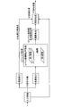
- FIG. 1 is a diagram for explaining the outline and features of the image processing apparatus according to the first embodiment.
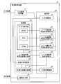
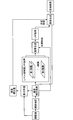
- FIG. 2 is a block diagram illustrating the configuration of the image processing apparatus according to the first embodiment.
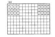
- FIG. 3 is a diagram illustrating the Y component decomposed from the input image.
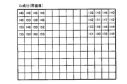
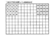
- FIG. 4 is a diagram illustrating Cr components decomposed from the input image.
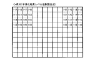
- FIG. 5 is a diagram illustrating the Cr component of the smoothed input image.
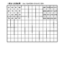
- FIG. 6 is a diagram illustrating a smoothed image obtained by combining the original images using the combining ratio.
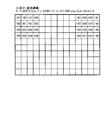
- FIG. 7 is a diagram illustrating a smoothed image that has been synthesized with an original image using a non-linear synthesis ratio in a high luminance range.
- FIG. 1 is a diagram for explaining the outline and features of the image processing apparatus according to the first embodiment.
- FIG. 2 is a block diagram illustrating the configuration of the image processing apparatus according to the first embodiment.
- FIG. 3 is a diagram illustrating the
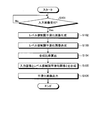
- FIG. 8 is a flowchart illustrating a process flow in the image processing apparatus according to the first embodiment.
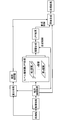
- FIG. 9 is a diagram illustrating the overall configuration of the image processing apparatus according to the second embodiment.
- FIG. 10 is a diagram illustrating the Y component decomposed from the original image according to the second embodiment.
- FIG. 11 is a diagram illustrating the Y component decomposed from the input image according to the second embodiment.
- FIG. 12 is a diagram illustrating the Y component of the smoothed input image.
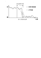
- FIG. 13 is a diagram illustrating the luminance correction amount.
- FIG. 14 is a diagram illustrating a smoothed image that is an original image synthesized using the synthesis ratio according to the second embodiment.
- FIG. 15 is a diagram illustrating an overall configuration of an image processing apparatus in a case where synthesis is performed using a contour cooperation amount.
- FIG. 16 is a diagram illustrating an example of a computer system that executes an image processing program.
- FIG. 17 is a diagram for explaining the related art.
- FIG. 18 is a diagram for explaining the prior art.
- FIG. 19 is a diagram for explaining the prior art.
- FIG. 20 is a diagram illustrating an example of an image processing apparatus using a discretized low-pass filter.
- FIG. 21 is a diagram for explaining the synthesis process in the image processing apparatus using the discretized low-pass filter.
- the “image processing apparatus (corresponding to the“ image processing apparatus ”recited in the claims”) ”used in this embodiment accepts an input image and image information, and generates an output image by smoothing the received input image.
- the input image may be a moving image or a still image, and may be color or monochrome.
- a technique using a discretized low-pass filter is conceivable as a technique for accurately storing an edge portion of an image and blurring other than the edge.
- different level value ranges are set, and a plurality of level limited low-pass filters (discretized low-pass filters) that generate a smoothed image only with pixels within the level value range are used in advance. It is conceivable to generate a plurality of smooth images, select a plurality of smoothing results, and interpolate to accurately preserve the edge portion and blur other than the edges.
- the “image processing apparatus” includes low-pass filters (LPFs) having different (discretized) level values from the first layer to the n-th layer, and each LPF starts with the horizontal direction of the input image.
- LPFs low-pass filters
- the LPF calculates an average value by accumulating the level values of the pixels determined to be within the level value range set for the pixel of the input image within the filter size, and the calculated average value Is the level value of the pixel of interest.
- the LPF similarly performs a one-dimensional filter process in the vertical direction on the image in which the horizontal filter process is performed on all pixels, and obtains each level value using all the pixels of the input image as the target pixel.
- a level value limited smoothed image is generated.
- the “image processing device” synthesizes the generated level value limited smoothed image to generate a smoothed image.
- the “average value” mentioned here includes a weighted average value. For example, regarding the position, if the level direction has the highest weight in the center in the filter area, the weight is set such that the center in the range is the highest weight.
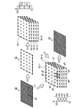
- the “image processing apparatus” includes a plurality of low-pass filters LPF0 to LPF4, and each of LPF0 to LPF4 includes 0 to 84 (P0) and 42 to 128 (P1). ), 85 to 160 (P2), 129 to 212 (P3), and 161 to 255 (P4).
- the “image processing apparatus” generates the reduced image 51 by extracting the pixels of the input image 50 every three pixels in the vertical direction and the horizontal direction. LPF0 to LPF4 then perform level value limited smoothing processing on the reduced image 51 to generate level value limited smoothed images 52-1 to 52-5.
- the image processing apparatus selects level value limited smoothed images 52-1 to 52-5 based on the level value of the pixel g1.
- the image processing apparatus selects the level value limited smoothed image 52-1, and the level value limited smoothed image 53-1 corresponding to the target pixel g1.
- the pixels g3 to g5 adjacent to the pixel g2 are selected.
- the image processing apparatus selects the level value limited smoothed image 53-1 from the pixels of the level value limited smoothed image 53-2 closest to the level value range of the selected level value limited smoothed image 53-1. Pixels g6 to g9 corresponding to the pixels g2 to g5 are selected.
- the “image processing apparatus” is the level value central value close to the level value (60) of the processing target pixel. If the weighted and input image is a reduced image so as to increase the weight of the pixel level value of the LPF 1 having the average value, the average value is further calculated using position information (vertical axis (X axis), horizontal axis (Y axis)). By calculating, the generated level value limited smoothed image is synthesized to generate a smoothed image. Specifically, the “image processing apparatus” is “LPF1 pixel level value ⁇ (25/43) + LPF0 pixel level value ⁇ (18/43)” or the like.
- the image processing apparatus includes a low-pass filter (LPF) having different level values from the first layer to the n-th layer, and a smoothed image obtained by blurring the input image from the input image.
- LPF low-pass filter
- the main feature is that the noise removal strength can be controlled quickly and easily.
- the image processing apparatus processes each pixel of the input image using a plurality of low-pass filters LPF # 0 to LPF # n each having a plurality of different level value ranges.
- the average value of each pixel included in the level value range is calculated from each pixel of the input image including the processing target pixel included in the filter size of the plurality of low-pass filters as the target pixel, and is limited by the plurality of level values.
- a plurality of level value limited smoothed images are generated (see (1) and (2) in FIG. 1).
- the image processing apparatus separates an input image into a color difference component and a luminance component, and uses an n-layer filter composed of LPF # 0 to LPF # n for the color difference component of the separated input image.
- a level value limited smoothed image is generated by the same method as described above.
- each of LPF # 0 to LPF # n refers to each pixel of the input image that has been input, acquires pixels within the level value range set for itself, and sets the level value of each acquired pixel. Accumulate and calculate (smooth) the average value.
- the image processing apparatus selects one or a plurality of the generated level value limited smoothed images, and synthesizes the selected level value limited smoothed images to generate a level value combined image (FIG. 1). (See (3)).
- the image processing apparatus selects a level value restriction conversion image corresponding to the level value of each pixel of the input image from a plurality of level value restriction conversion images generated by the respective filters.
- the image processing apparatus combines a plurality of level value limited conversion images selected for each pixel of the input image to generate a level value limited combined image that is one combined image (frame).
- the level value limited smoothed image is synthesized by the same method as described above.
- the image processing apparatus separates an input image that is different from a color difference component that is image information relating to an image constituting an input image used when a plurality of level value limited smoothed images are generated. Based on the luminance component obtained in this way, the composition ratio between the input image as the original image and the generated level value limited composite image is determined. For example, in the above-described example, when the luminance component different from the color difference component of the input image used when the plurality of level value limited smoothed images are generated has a large value, the ratio of the input image is increased and the level value is increased.
- the composition ratio is determined so as to reduce the ratio of the limited composite image, and if the luminance component is small, the composition ratio is determined so that the ratio of the input image is low and the ratio of the level value limited composite image is high. . Then, the image processing apparatus generates a smoothed image by combining the level value combined image and the input image based on the determined combining ratio.
- the image processing apparatus can perform high-speed edge preserving smoothing processing according to an image component that is not the image component itself to be processed, and is independent of the discretized low-pass filter. As a result of synthesizing the level value limited composite image and the input image, it is possible to control the noise removal intensity at high speed and easily as described above.
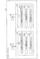
- FIG. 2 is a block diagram illustrating the configuration of the image processing apparatus according to the first embodiment.
- the image processing apparatus 10 includes an input image receiving unit 11, a storage unit 20, a control unit 30, and an image output unit 40.
- the input image receiving unit 11 receives moving image data and the like from the outside. Specifically, the input image receiving unit 11 receives moving image data from the outside frame by frame, and stores the received frame as an input image in an input image DB 21 described later.
- the input image receiving unit 11 may receive an input image from an external device via a network or the like, or may be received from a storage medium such as a CD-ROM or a DVD.
- the input image may be a moving image or a still image, and may be color or monochrome. Further, the input image may be a reduced image, and in that case, an enlargement process is executed in the smoothed image generation unit 34 described later.
- the storage unit 20 stores data and programs necessary for various types of processing by the control unit 30, and particularly those closely related to the present invention include an input image DB21, a level value limited smoothed image # 0DB22, a level A value limited smoothed image # 1DB23, a level value limited smoothed image # nDB24, a level value limited composite image DB25, and a smoothed image DB26 are provided.
- the input image DB 21 stores frames input to the image processing apparatus 10.
- the input image DB 21 stores the Nth frame, the N + 1th frame, and the like of the moving image data stored by the input image receiving unit 11.
- the level value limited smoothed image # 0DB22 stores a plurality of smoothed images of level values (for example, 0 to 40 pixels) stored by the LPF # 0 and similarly, the level value limited smoothed image # 1DB23 stores a plurality of smoothed images of level values (for example, 30 to 60 pixels) stored by LPF # 1, and level value limited smoothed image # nDB24 stores level values stored by LPF # n.
- a plurality of smoothed images (for example, 210 pixels to 255 pixels) are stored.
- the control unit 30 has a control program such as an OS (Operating System), a program that defines various processing procedures, and an internal memory for storing necessary data.
- OS Operating System
- the control unit 30 is closely related to the present invention.
- a filter processing unit 31, a level value limited smoothed image synthesis unit 32, a synthesis ratio determination unit 33, and a smoothed image generation unit 34 are provided, and various processes are executed by these.
- the filter processing unit 31 performs a filtering process on the color difference components of the input image using a plurality of low-pass filters in which a plurality of different level value ranges are set, and generates a plurality of filtering results.
- a filtering process on the color difference components of the input image using a plurality of low-pass filters in which a plurality of different level value ranges are set, and generates a plurality of filtering results.
- LPF # 0 to LPF # n use each pixel of the input image as a processing target pixel, and each pixel included in the level value range from each pixel of the input image including the processing target pixel included in the filter size of the plurality of low-pass filters. An average value of pixels is calculated, and a plurality of level value limited smoothed images limited by a plurality of level values are generated.
- LPF # 0 to LPF # n are one-dimensional low-pass filters, and different level value ranges are set in advance.
- a level value limited smoothed image is generated by performing level value limited smoothing processing that smoothes (calculates an average value) the pixels within the level value range set for itself as a processing target, and the generated level value
- the restricted smoothed image is stored in the corresponding level value restricted smoothed image DB (for example, in the case of LPF # 0, the level value restricted smoothed image DB # 0).
- the level value range set in the LPF is preferably such that a part of the range overlaps at least two LPFs, but it is only necessary to cover the level value range of the input image.
- the filter size and level value range of the LPF may be set to fixed values or may be set from the outside.
- the synthesis ratio determination unit 33 is configured to generate the first image based on image information different from image information related to an image constituting an input image used when the filter processing unit 31 generates a plurality of level value limited smoothed images.
- the synthesis ratio between the level value synthesized image synthesized by the synthesis means and the input image is determined, and the determined synthesized ratio is notified to the smoothed image generation unit 34.
- the composition ratio determination unit 33 is different from the color difference component that is image information relating to an image constituting an input image used when a plurality of level value limited smoothed images are generated. Based on the luminance component obtained by separating the input image, the composition ratio between the input image as the original image and the generated level value limited composite image is determined.
- the synthesis ratio determination unit 33 increases the noise removal strength of the low luminance portion and weakens the noise removal strength of the high luminance portion as described above.
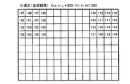
- “Out (L * (255 ⁇ Y) + In * Y) / 255” using In, LPF result as L, output as Out, and luminance Y of the corresponding pixel is determined as a synthesis ratio, and the smoothed image generation unit 34 Using this determined calculation formula, as shown in FIG. 6, the input image (see FIG. 4) and the level value limited composite image (see FIG. 5) are synthesized as an original image.
- the smoothed image shown in FIG. 6 synthesized with the original image includes the input image (original image) shown in FIG.
- the image output unit 40 outputs the generated smoothed image to another connected device.
- the image output unit 40 acquires a smoothed image generated by the smoothed image generating unit 34 and stored in the smoothed image DB 2, for example, dynamic range compression that cleans a backlight image or the like. To output to a dynamic range device that generates an image.
- the synthesized level value synthesized image and the input image are synthesized based on a component different from the processing target component used when the plurality of level value limited smoothed images are generated. Since the ratio is determined and the smoothed image is generated by combining the level value composite image and the input image using the determined composite ratio, the noise removal strength depends on the image component that is not the image component itself to be processed. Can be controlled at high speed and easily.
- the image processing apparatus calculates a difference between the original image and the input image when the input image and the level value limited combined image are combined (original image combination).
- a synthesis ratio is determined based on the luminance correction amount that is the difference, and a smoothed image is generated by synthesizing the input image and the level value limited composite image using the determined synthesis ratio.
- the smoothed image generating unit 34 uses the determined calculation formula (composition ratio), as shown in FIG. 14, and the input image (see FIG. 11) and the level value limited composite image (see FIG. 12). To generate a smoothed image.
- the ratio of the input image (see FIG. 11) is large in the upper left of the figure where the luminance correction amount is small, and the level value limited synthesized image (see FIG. 12) is in the upper right of the figure where the luminance correction amount is large. It can be seen that the ratio has increased.
- the composition ratio between the combined level value composite image and the input image is determined. Since the smoothed image is generated by combining the level value combined image and the input image using the determined combining ratio, it is possible to control the noise removal strength according to the correction amount for the luminance.
- the above-mentioned programs 103a to 103c are not necessarily stored in the ROM 103.
- a flexible disk (FD), a CD-ROM, an MO disk, a DVD disk, a magneto-optical disk inserted into the computer system 100 In addition to “portable physical media” such as IC cards, “fixed physical media” such as hard disk drives (HDDs) provided inside and outside the computer system 100, public lines, the Internet, LAN, WAN, etc.
- the program may be stored in “another computer system” connected to the computer system 100 via the computer system 100 so that the computer system 100 reads and executes the program.
Landscapes
- Physics & Mathematics (AREA)
- General Physics & Mathematics (AREA)
- Engineering & Computer Science (AREA)
- Theoretical Computer Science (AREA)
- Image Processing (AREA)
- Facsimile Image Signal Circuits (AREA)
Abstract
Dans cet appareil de traitement d'image, une pluralité de filtres passe-bas dans lesquels sont définies une pluralité de différentes plages de valeurs de niveau sont utilisés et chaque pixel d'une image entrée constitue une cible de traitement ; une moyenne de chaque pixel compris dans une plage de valeurs de niveau est calculée à partir de chaque pixel d'une image entrée comprenant une image devant être traitée comprise dans une taille de filtre de la pluralité de filtres passe-bas de façon à créer une pluralité d'images de lissage des limites de valeurs de niveau limitées par une pluralité de valeurs de niveau ; une ou plusieurs images de lissage des limites de valeurs de niveau créées sont sélectionnées de manière à synthétiser l'image de lissage des limites de valeurs de niveau sélectionnée et à créer une image synthétique de valeurs de niveau ; le rapport synthétique de l'image synthétique de valeurs de niveau et de l'image entrée est déterminé sur la base des informations d'images qui sont différentes des informations d'image relatives à une image formant une image entrée utilisée lors de la création de la pluralité d'images de lissage des limites de valeurs de niveau ; et l'image synthétique de valeurs de niveau ainsi que l'image entrée sont synthétisées de façon à créer une image de lissage en utilisant le rapport synthétique déterminé.
Priority Applications (3)
| Application Number | Priority Date | Filing Date | Title |
|---|---|---|---|
| JP2009546901A JP4952796B2 (ja) | 2007-12-25 | 2007-12-25 | 画像処理装置 |
| PCT/JP2007/074841 WO2009081485A1 (fr) | 2007-12-25 | 2007-12-25 | Appareil de traitement d'image, procédé de traitement d'image et programme de traitement d'image |
| US12/801,665 US8311356B2 (en) | 2007-12-25 | 2010-06-18 | Image processing apparatus and image processing method |
Applications Claiming Priority (1)
| Application Number | Priority Date | Filing Date | Title |
|---|---|---|---|
| PCT/JP2007/074841 WO2009081485A1 (fr) | 2007-12-25 | 2007-12-25 | Appareil de traitement d'image, procédé de traitement d'image et programme de traitement d'image |
Related Child Applications (1)
| Application Number | Title | Priority Date | Filing Date |
|---|---|---|---|
| US12/801,665 Continuation US8311356B2 (en) | 2007-12-25 | 2010-06-18 | Image processing apparatus and image processing method |
Publications (1)
| Publication Number | Publication Date |
|---|---|
| WO2009081485A1 true WO2009081485A1 (fr) | 2009-07-02 |
Family
ID=40800803
Family Applications (1)
| Application Number | Title | Priority Date | Filing Date |
|---|---|---|---|
| PCT/JP2007/074841 Ceased WO2009081485A1 (fr) | 2007-12-25 | 2007-12-25 | Appareil de traitement d'image, procédé de traitement d'image et programme de traitement d'image |
Country Status (3)
| Country | Link |
|---|---|
| US (1) | US8311356B2 (fr) |
| JP (1) | JP4952796B2 (fr) |
| WO (1) | WO2009081485A1 (fr) |
Cited By (2)
| Publication number | Priority date | Publication date | Assignee | Title |
|---|---|---|---|---|
| JP2012068733A (ja) * | 2010-09-21 | 2012-04-05 | Olympus Corp | 画像処理装置および画像処理プログラム |
| US9355327B2 (en) | 2013-06-19 | 2016-05-31 | Hitachi Industry & Control Solutions, Ltd. | Image processing apparatus and imaging apparatus with noise correction function and signal level correction function |
Families Citing this family (11)
| Publication number | Priority date | Publication date | Assignee | Title |
|---|---|---|---|---|
| JP4527750B2 (ja) * | 2007-05-30 | 2010-08-18 | 三菱電機株式会社 | 画像処理装置及び方法並びに画像表示装置 |
| US8300974B2 (en) * | 2007-11-12 | 2012-10-30 | Mitsubishi Electric Corporation | Image processing device, image display device, and image processing method therefor |
| TW200930044A (en) * | 2007-12-28 | 2009-07-01 | Altek Corp | False color depressing method for digital images |
| JP2012178042A (ja) * | 2011-02-25 | 2012-09-13 | Canon Inc | 画像形成装置、画像形成方法及びプログラム |
| JP5585494B2 (ja) * | 2011-02-28 | 2014-09-10 | 富士通株式会社 | 画像処理装置、画像処理プログラム及び画像処理方法 |
| US9324137B2 (en) * | 2012-10-24 | 2016-04-26 | Marvell World Trade Ltd. | Low-frequency compression of high dynamic range images |
| US10326969B2 (en) * | 2013-08-12 | 2019-06-18 | Magna Electronics Inc. | Vehicle vision system with reduction of temporal noise in images |
| LU92673B1 (en) * | 2015-03-05 | 2016-09-06 | Iee Int Electronics & Eng Sa | Method and system for real-time noise removal and image enhancement of high-dynamic range images |
| TWI638336B (zh) * | 2017-11-22 | 2018-10-11 | 瑞昱半導體股份有限公司 | 影像增強方法及影像增強裝置 |
| CN109862338B (zh) * | 2017-11-30 | 2021-03-02 | 瑞昱半导体股份有限公司 | 影像增强方法及影像增强装置 |
| JP2023160661A (ja) * | 2022-04-22 | 2023-11-02 | キヤノン株式会社 | 画像処理装置、画像処理方法、及びコンピュータプログラム |
Citations (6)
| Publication number | Priority date | Publication date | Assignee | Title |
|---|---|---|---|---|
| JPH09270005A (ja) * | 1996-04-03 | 1997-10-14 | Matsushita Electric Ind Co Ltd | エッジ画像処理装置およびエッジ画像処理方法 |
| JP2003008898A (ja) * | 2001-06-20 | 2003-01-10 | Sony Corp | 画像処理方法および装置 |
| JP2004172726A (ja) * | 2002-11-18 | 2004-06-17 | Sony Corp | 画像処理装置および方法 |
| JP2005328277A (ja) * | 2004-05-13 | 2005-11-24 | Sony Corp | 信号処理装置および方法、記録媒体、並びにプログラム |
| WO2007097125A1 (fr) * | 2006-02-27 | 2007-08-30 | Nikon Corporation | Dispositif de traitement d'image pour corriger une perception massive d'image, programme et procede de traitement d'image, et camera electronique |
| WO2007129367A1 (fr) * | 2006-04-25 | 2007-11-15 | Mitsubishi Denki Kabushiki Kaisha | Appareil de combinaison d'images et procédé de combinaison d'images |
Family Cites Families (7)
| Publication number | Priority date | Publication date | Assignee | Title |
|---|---|---|---|---|
| US5048109A (en) * | 1989-12-08 | 1991-09-10 | Xerox Corporation | Detection of highlighted regions |
| KR940007346B1 (ko) * | 1991-03-28 | 1994-08-13 | 삼성전자 주식회사 | 화상 처리 시스템의 엣지 검출 장치 |
| US6023535A (en) * | 1995-08-31 | 2000-02-08 | Ricoh Company, Ltd. | Methods and systems for reproducing a high resolution image from sample data |
| US5799112A (en) * | 1996-08-30 | 1998-08-25 | Xerox Corporation | Method and apparatus for wavelet-based universal halftone image unscreening |
| JP2000105815A (ja) | 1998-09-28 | 2000-04-11 | Yasuhiko Arakawa | 顔画像処理方法および顔画像処理装置 |
| US7440612B2 (en) * | 1998-11-13 | 2008-10-21 | Sony Corporation | Image processing apparatus and method capable of correcting gradation of image data |
| US6665448B1 (en) * | 2000-09-29 | 2003-12-16 | Hewlett-Packard Development Company, L.P. | Selective smoothing and sharpening of images by generalized unsharp masking |
-
2007
- 2007-12-25 WO PCT/JP2007/074841 patent/WO2009081485A1/fr not_active Ceased
- 2007-12-25 JP JP2009546901A patent/JP4952796B2/ja not_active Expired - Fee Related
-
2010
- 2010-06-18 US US12/801,665 patent/US8311356B2/en active Active
Patent Citations (6)
| Publication number | Priority date | Publication date | Assignee | Title |
|---|---|---|---|---|
| JPH09270005A (ja) * | 1996-04-03 | 1997-10-14 | Matsushita Electric Ind Co Ltd | エッジ画像処理装置およびエッジ画像処理方法 |
| JP2003008898A (ja) * | 2001-06-20 | 2003-01-10 | Sony Corp | 画像処理方法および装置 |
| JP2004172726A (ja) * | 2002-11-18 | 2004-06-17 | Sony Corp | 画像処理装置および方法 |
| JP2005328277A (ja) * | 2004-05-13 | 2005-11-24 | Sony Corp | 信号処理装置および方法、記録媒体、並びにプログラム |
| WO2007097125A1 (fr) * | 2006-02-27 | 2007-08-30 | Nikon Corporation | Dispositif de traitement d'image pour corriger une perception massive d'image, programme et procede de traitement d'image, et camera electronique |
| WO2007129367A1 (fr) * | 2006-04-25 | 2007-11-15 | Mitsubishi Denki Kabushiki Kaisha | Appareil de combinaison d'images et procédé de combinaison d'images |
Cited By (2)
| Publication number | Priority date | Publication date | Assignee | Title |
|---|---|---|---|---|
| JP2012068733A (ja) * | 2010-09-21 | 2012-04-05 | Olympus Corp | 画像処理装置および画像処理プログラム |
| US9355327B2 (en) | 2013-06-19 | 2016-05-31 | Hitachi Industry & Control Solutions, Ltd. | Image processing apparatus and imaging apparatus with noise correction function and signal level correction function |
Also Published As
| Publication number | Publication date |
|---|---|
| US8311356B2 (en) | 2012-11-13 |
| JP4952796B2 (ja) | 2012-06-13 |
| JPWO2009081485A1 (ja) | 2011-05-06 |
| US20100260432A1 (en) | 2010-10-14 |
Similar Documents
| Publication | Publication Date | Title |
|---|---|---|
| JP4952796B2 (ja) | 画像処理装置 | |
| JP4847591B2 (ja) | 画像処理装置、画像処理方法および画像処理プログラム | |
| JP4707830B2 (ja) | テクスチャのノイズ依存制御を有するディジタル画像を改善する方法 | |
| JP5495025B2 (ja) | 画像処理装置および方法、並びにプログラム | |
| JP4998287B2 (ja) | 画像処理装置および方法、並びにプログラム | |
| JP5136665B2 (ja) | 画像処理装置、及びプログラム | |
| JP4556276B2 (ja) | 画像処理回路及び画像処理方法 | |
| JPWO2009107197A1 (ja) | 画像処理装置、画像処理方法および画像処理プログラム | |
| WO2016031189A1 (fr) | Appareil de traitement d'image, procédé de traitement d'image, support d'enregistrement, et programme | |
| EP1111906A2 (fr) | Procédé pour rehausser le contraste du bord d'une image numérique indépendent de texture | |
| JP2008310117A (ja) | 画像処理装置、画像処理方法、画像処理方法のプログラム及び画像処理方法のプログラムを記録した記録媒体 | |
| CN102737363A (zh) | 图像处理设备和方法以及程序 | |
| JP4526445B2 (ja) | 撮像装置 | |
| JP4523926B2 (ja) | 画像処理装置、画像処理プログラムおよび画像処理方法 | |
| JP4962573B2 (ja) | 画像処理装置 | |
| JP5295854B2 (ja) | 画像処理装置及び画像処理プログラム | |
| JP4847531B2 (ja) | 画像処理装置、画像処理プログラム、および画像処理方法 | |
| JP4277550B2 (ja) | 信号処理装置および方法、記録媒体、並びにプログラム | |
| Jin et al. | 23‐2: An Adaptive Contrast Enhancement of Image Using Multi‐Scale Histogram Representation | |
| JP5761195B2 (ja) | 画像処理装置、画像処理プログラム及び画像処理方法 | |
| JP4207381B2 (ja) | 画像処理装置、画像処理方法、および記録媒体 | |
| WO2004097738A1 (fr) | Dispositif et methode de traitement de signal, support d'enregistrement, et programme associe | |
| JP4992438B2 (ja) | 画像処理装置および画像処理プログラム | |
| JP4053167B2 (ja) | 画像処理方法および装置 | |
| JP6891014B2 (ja) | 画像処理装置および画像処理方法、並びにプログラム |
Legal Events
| Date | Code | Title | Description |
|---|---|---|---|
| 121 | Ep: the epo has been informed by wipo that ep was designated in this application |
Ref document number: 07860070 Country of ref document: EP Kind code of ref document: A1 |
|
| WWE | Wipo information: entry into national phase |
Ref document number: 2009546901 Country of ref document: JP |
|
| NENP | Non-entry into the national phase |
Ref country code: DE |
|
| 122 | Ep: pct application non-entry in european phase |
Ref document number: 07860070 Country of ref document: EP Kind code of ref document: A1 |