WO2009081640A1 - 洗濯機 - Google Patents
洗濯機 Download PDFInfo
- Publication number
- WO2009081640A1 WO2009081640A1 PCT/JP2008/068297 JP2008068297W WO2009081640A1 WO 2009081640 A1 WO2009081640 A1 WO 2009081640A1 JP 2008068297 W JP2008068297 W JP 2008068297W WO 2009081640 A1 WO2009081640 A1 WO 2009081640A1
- Authority
- WO
- WIPO (PCT)
- Prior art keywords
- water
- washing
- rinsing
- washing tub
- circulation
- Prior art date
- Legal status (The legal status is an assumption and is not a legal conclusion. Google has not performed a legal analysis and makes no representation as to the accuracy of the status listed.)
- Ceased
Links
Images


Classifications
-
- D—TEXTILES; PAPER
- D06—TREATMENT OF TEXTILES OR THE LIKE; LAUNDERING; FLEXIBLE MATERIALS NOT OTHERWISE PROVIDED FOR
- D06F—LAUNDERING, DRYING, IRONING, PRESSING OR FOLDING TEXTILE ARTICLES
- D06F25/00—Washing machines with receptacles, e.g. perforated, having a rotary movement, e.g. oscillatory movement, the receptacle serving both for washing and for centrifugally separating water from the laundry and having further drying means, e.g. using hot air
-
- D—TEXTILES; PAPER
- D06—TREATMENT OF TEXTILES OR THE LIKE; LAUNDERING; FLEXIBLE MATERIALS NOT OTHERWISE PROVIDED FOR
- D06F—LAUNDERING, DRYING, IRONING, PRESSING OR FOLDING TEXTILE ARTICLES
- D06F33/00—Control of operations performed in washing machines or washer-dryers
- D06F33/30—Control of washing machines characterised by the purpose or target of the control
- D06F33/32—Control of operational steps, e.g. optimisation or improvement of operational steps depending on the condition of the laundry
-
- D—TEXTILES; PAPER
- D06—TREATMENT OF TEXTILES OR THE LIKE; LAUNDERING; FLEXIBLE MATERIALS NOT OTHERWISE PROVIDED FOR
- D06F—LAUNDERING, DRYING, IRONING, PRESSING OR FOLDING TEXTILE ARTICLES
- D06F35/00—Washing machines, apparatus, or methods not otherwise provided for
- D06F35/001—Washing machines, apparatus, or methods not otherwise provided for using ozone
-
- D—TEXTILES; PAPER
- D06—TREATMENT OF TEXTILES OR THE LIKE; LAUNDERING; FLEXIBLE MATERIALS NOT OTHERWISE PROVIDED FOR
- D06F—LAUNDERING, DRYING, IRONING, PRESSING OR FOLDING TEXTILE ARTICLES
- D06F39/00—Details of washing machines not specific to a single type of machines covered by groups D06F9/00 - D06F27/00
- D06F39/08—Liquid supply or discharge arrangements
- D06F39/083—Liquid discharge or recirculation arrangements
-
- D—TEXTILES; PAPER
- D06—TREATMENT OF TEXTILES OR THE LIKE; LAUNDERING; FLEXIBLE MATERIALS NOT OTHERWISE PROVIDED FOR
- D06F—LAUNDERING, DRYING, IRONING, PRESSING OR FOLDING TEXTILE ARTICLES
- D06F39/00—Details of washing machines not specific to a single type of machines covered by groups D06F9/00 - D06F27/00
- D06F39/08—Liquid supply or discharge arrangements
- D06F39/088—Liquid supply arrangements
-
- D—TEXTILES; PAPER
- D06—TREATMENT OF TEXTILES OR THE LIKE; LAUNDERING; FLEXIBLE MATERIALS NOT OTHERWISE PROVIDED FOR
- D06F—LAUNDERING, DRYING, IRONING, PRESSING OR FOLDING TEXTILE ARTICLES
- D06F2103/00—Parameters monitored or detected for the control of domestic laundry washing machines, washer-dryers or laundry dryers
- D06F2103/18—Washing liquid level
-
- D—TEXTILES; PAPER
- D06—TREATMENT OF TEXTILES OR THE LIKE; LAUNDERING; FLEXIBLE MATERIALS NOT OTHERWISE PROVIDED FOR
- D06F—LAUNDERING, DRYING, IRONING, PRESSING OR FOLDING TEXTILE ARTICLES
- D06F2105/00—Systems or parameters controlled or affected by the control systems of washing machines, washer-dryers or laundry dryers
- D06F2105/02—Water supply
-
- D—TEXTILES; PAPER
- D06—TREATMENT OF TEXTILES OR THE LIKE; LAUNDERING; FLEXIBLE MATERIALS NOT OTHERWISE PROVIDED FOR
- D06F—LAUNDERING, DRYING, IRONING, PRESSING OR FOLDING TEXTILE ARTICLES
- D06F2105/00—Systems or parameters controlled or affected by the control systems of washing machines, washer-dryers or laundry dryers
- D06F2105/08—Draining of washing liquids
-
- D—TEXTILES; PAPER
- D06—TREATMENT OF TEXTILES OR THE LIKE; LAUNDERING; FLEXIBLE MATERIALS NOT OTHERWISE PROVIDED FOR
- D06F—LAUNDERING, DRYING, IRONING, PRESSING OR FOLDING TEXTILE ARTICLES
- D06F2105/00—Systems or parameters controlled or affected by the control systems of washing machines, washer-dryers or laundry dryers
- D06F2105/52—Changing sequence of operational steps; Carrying out additional operational steps; Modifying operational steps, e.g. by extending duration of steps
-
- D—TEXTILES; PAPER
- D06—TREATMENT OF TEXTILES OR THE LIKE; LAUNDERING; FLEXIBLE MATERIALS NOT OTHERWISE PROVIDED FOR
- D06F—LAUNDERING, DRYING, IRONING, PRESSING OR FOLDING TEXTILE ARTICLES
- D06F2105/00—Systems or parameters controlled or affected by the control systems of washing machines, washer-dryers or laundry dryers
- D06F2105/56—Remaining operation time; Remaining operational cycles
-
- D—TEXTILES; PAPER
- D06—TREATMENT OF TEXTILES OR THE LIKE; LAUNDERING; FLEXIBLE MATERIALS NOT OTHERWISE PROVIDED FOR
- D06F—LAUNDERING, DRYING, IRONING, PRESSING OR FOLDING TEXTILE ARTICLES
- D06F33/00—Control of operations performed in washing machines or washer-dryers
- D06F33/30—Control of washing machines characterised by the purpose or target of the control
- D06F33/32—Control of operational steps, e.g. optimisation or improvement of operational steps depending on the condition of the laundry
- D06F33/34—Control of operational steps, e.g. optimisation or improvement of operational steps depending on the condition of the laundry of water filling
-
- D—TEXTILES; PAPER
- D06—TREATMENT OF TEXTILES OR THE LIKE; LAUNDERING; FLEXIBLE MATERIALS NOT OTHERWISE PROVIDED FOR
- D06F—LAUNDERING, DRYING, IRONING, PRESSING OR FOLDING TEXTILE ARTICLES
- D06F33/00—Control of operations performed in washing machines or washer-dryers
- D06F33/30—Control of washing machines characterised by the purpose or target of the control
- D06F33/32—Control of operational steps, e.g. optimisation or improvement of operational steps depending on the condition of the laundry
- D06F33/36—Control of operational steps, e.g. optimisation or improvement of operational steps depending on the condition of the laundry of washing
-
- D—TEXTILES; PAPER
- D06—TREATMENT OF TEXTILES OR THE LIKE; LAUNDERING; FLEXIBLE MATERIALS NOT OTHERWISE PROVIDED FOR
- D06F—LAUNDERING, DRYING, IRONING, PRESSING OR FOLDING TEXTILE ARTICLES
- D06F33/00—Control of operations performed in washing machines or washer-dryers
- D06F33/30—Control of washing machines characterised by the purpose or target of the control
- D06F33/32—Control of operational steps, e.g. optimisation or improvement of operational steps depending on the condition of the laundry
- D06F33/38—Control of operational steps, e.g. optimisation or improvement of operational steps depending on the condition of the laundry of rinsing
-
- D—TEXTILES; PAPER
- D06—TREATMENT OF TEXTILES OR THE LIKE; LAUNDERING; FLEXIBLE MATERIALS NOT OTHERWISE PROVIDED FOR
- D06F—LAUNDERING, DRYING, IRONING, PRESSING OR FOLDING TEXTILE ARTICLES
- D06F35/00—Washing machines, apparatus, or methods not otherwise provided for
- D06F35/002—Washing machines, apparatus, or methods not otherwise provided for using bubbles
Definitions
- the present invention relates to a washing machine, and more particularly to a washing machine that performs washing by mixing purifying air into washing water.
- the present applicant has previously proposed a washing machine equipped with a mechanism for purifying water used for washing using ozone.
- the washing machine described in Patent Literature 1 includes a water storage tank, and has a configuration for purifying water stored in the water storage tank using ozone. Further, the applicant of the present application has proposed a rinsing method capable of rinsing clothes stains and detergent components with a small number of times of rinsing and a washing machine for executing the rinsing method.
- See Patent Document 2 JP 2007-181608 A JP 2007-181597 A
- the washing machine disclosed in Patent Document 1 is configured such that the water used for washing is stored in a water storage tank and can be reused by purifying the stored water with ozone. is there.
- a washing machine that can perform better washing with the purified water by performing the washing operation while purifying the water used for washing during washing instead of the water after washing. It is desired.
- a washing machine capable of rinsing clothes stains and detergent components well in the rinsing process is desired, and a washing machine capable of performing the rinsing process using bath water is also desired.
- the present invention has been made based on such a background, and a main object of the present invention is to provide a washing machine that can use bath water for rinsing and that can perform good rinsing.
- the present invention relates to a washing water tank, a water supply valve that is opened and closed to supply tap water to the washing water tank, a bath water pump that is driven to supply bath water to the washing water tank, and both ends of the washing water tank.
- a circulation water channel connected to the circulation water channel, and a circulation pump provided in the circulation water channel for pumping out water in the washing tub from one end of the circulation water channel and discharging the pumped water from the other end of the circulation water channel into the washing tub
- a purification air generator for generating purification air
- a gas-liquid mixer for mixing the purification air generated by the purification air generator into the water flowing in the circulation water channel
- the purification air generator is operated to mix the purification air into the water circulated by driving the circulation pump.
- the bath water purification control means may operate the purification air generator for a preset time longer than when tap water is supplied.
- the washing machine of the present invention is a washing machine in which detergent water in which detergent is dissolved is stored in the washing tub, and a washing process is performed, and then a rinsing process is performed.
- the bath water purification control means functions only in the rinsing process. It is preferable.
- the washing machine of the present invention is a washing machine that performs an intermediate dehydration process for dehydrating the detergent water used in the washing process when proceeding from the washing process to the rinsing process, and a rinsing process using tap water is performed.
- intermediate dehydration control means for extending the dehydration time of the intermediate dehydration process when proceeding to the rinsing process in which the bath water purification control means functions.
- the washing machine of the present invention includes a drain valve for draining water from the washing tub with respect to the bath water supply when the bath water pump is driven to supply the bath water to the washing tub in the rinsing step. You may have the water supply / drainage control means opened and closed by predetermined correspondence.
- the rinsing process in which the bath water purification control means functions includes a plurality of rinsing processes, and an intermediate dehydration process is inserted before each rinsing process, which is performed in advance.
- the dehydration time of the intermediate dehydration process performed before the rinsing process may be longer than the dehydration time of the intermediate dehydration process performed before the subsequent rinsing process.
- the rinsing process in which the bath water purification control unit functions includes a plurality of rinsing processes, and the bath water supply time in the rinsing process performed in advance is the bath water supply in the rinsing process performed subsequently. It may be longer than the time.
- the rinsing process in which the bath water purification control means functions includes a plurality of rinsing processes, and in the final rinsing process performed last, the operation of the purification air generator is stopped to wash the softener. Finishing processing control means for feeding into the water tank may be included.
- the bath water pump since the bath water pump is provided, the bath water can be stored in the washing tub and used as washing water or rinsing water. Further, since the circulation water channel and the circulation pump are provided, the water in the washing tub can be circulated through the circulation water channel. Further, since the purifying air generator and the gas-liquid mixer are provided, the purifying air can be mixed into the water circulating through the circulation water channel to purify the water stored in the washing tub.
- the bath water purification control means is preferably configured to circulate the water in the washing tub for a preset time longer than when tap water is supplied. Then, control is performed so that purification air is mixed into the circulating water. Therefore, the bath water stored in the washing tub can be purified well.
- the bath water often contains germs and the like, but such germs and the like are purified by mixing the purifying air for a long time, so that hygiene and good washing can be performed. That is, hygienic and good washing can be performed using bath water.
- the bath water purification control means may function only in the rinsing process, and purification may be performed by mixing purification air into the bath water only in the rinsing process.
- the reason is that even if purification air is mixed into the detergent water used in the washing process, the purification air is combined with the detergent component and consumed by the detergent component. Can hardly be decomposed and purified. Therefore, the wasteful operation with poor purification efficiency of mixing the purification air into the detergent water is not performed, and only in the rinsing step, the circulation pump is driven and the purification air generator is operated efficiently. And bath water can be purified effectively.
- the function of the detergent component contained in the detergent water is not hindered by the purification air, and good washing can be performed.
- good rinsing can be realized while purifying bath water and sanitizing clothes.
- the dehydration time of the intermediate dehydration process may be lengthened. If the dehydration time of the intermediate dehydration process is long, the detergent water contained in the laundry is sufficiently removed, so that the residual detergent components are reduced when bath water is supplied in the rinse process.
- the detergent water used in the washing step can be sufficiently reduced by lengthening the dehydration time in the intermediate dehydration step, and bath water can be satisfactorily purified in the rinse step.
- bath water supplied to the washing tub if bath water supplied to the washing tub is drained while draining part of the bath water supplied to the washing tub, bath water is supplied to the washing tub. When is accumulated, the residual detergent components in the accumulated bath water can be reduced. Therefore, when the bath water purification control means functions in the rinsing process, the bath water is purified well.
- the dehydration time of the intermediate dehydration step before the first rinsing step is made longer than the dehydration time of the subsequent intermediate dehydration step. Is preferred.
- a residual detergent component can be reduced efficiently and bath water can be efficiently purified with the purification air in the rinsing step.
- the laundry can be efficiently rinsed by dividing the rinsing process into a plurality of rinsing processes. More specifically, when the rinsing process is divided into, for example, the rinsing process 1 and the rinsing process 2, in the rinsing process 1, the detergent water used in the washing process remains in the laundry to be rinsed. It is thought that there are relatively many residual detergent components in water. Therefore, the bath water supply time is relatively increased to dilute the remaining detergent components.
- the bath water supply time is relatively shortened. Thereby, shortening of the rinsing time and efficient rinsing can be realized.
- finishing process control means stops the operation of the purifying air generator when the softening agent is put into the washing tub. Therefore, the softener is not decomposed or disabled by the purification air, and the washing machine can be operated without any trouble.
- a good rinsing process can be performed using bath water in the rinsing step.
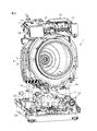
- FIG. 1 is a right side view of a longitudinal section of a washing / drying machine 1 according to an embodiment of the present invention. It is the perspective view which looked at the washing-drying machine 1 from diagonally forward, and is a figure which shows the internal structure from which the housing
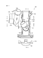
- FIG. 4 is a perspective view showing specific configurations of a U-turn part 26 and a gas-liquid mixer 27.
- 3 is a longitudinal sectional view showing the internal structure of the gas-liquid mixer 27.
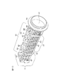
- FIG. 3 is a perspective view of the filter unit 15.
- FIG. 4 is a perspective view showing a configuration of a filter body 85.
- FIG. FIG. 4 is a perspective view showing a configuration of a filter body 85.
- FIG. 5 is a perspective view showing a configuration of a basket 84 alone with an operation lid 85 removed from a filter body 83.
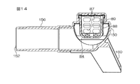
- 3 is a plan view of the filter unit 15.
- FIG. FIG. 12 is a longitudinal sectional view of the filter unit 15 along AA in FIG. 11.
- FIG. 12 is a cross-sectional view of the filter unit 15 along BB in FIG. 11.
- FIG. 12 is a transverse cross-sectional view of the filter unit 15 along CC in FIG. 11.
- 3 is a block diagram for explaining a configuration of an electrical control circuit of the washing / drying machine 1.
- FIG. It is a flowchart for demonstrating the content of the operation control of the washing process and the rinse process of the washing / drying machine 1 using a tap water.
- FIG. 1 is a right side view of a longitudinal section of a washing / drying machine 1 according to an embodiment of the present invention.
- the washing / drying machine 1 includes a washing tub 3 disposed obliquely in a housing (housing) 2.
- the washing tub 3 includes an outer tub 4 for collecting water during washing and a drum 5 rotatably accommodated in the outer tub 4.
- the drum 5 is rotated around a rotation shaft 7 by a DD motor 6 provided behind the outer tub 4.
- the rotating shaft 7 extends obliquely upward toward the front and has a so-called oblique drum structure.
- the entrance 8 of the drum 5 and the entrance 9 of the outer tub 4 are opened and closed by a door 10 attached to the housing 2.
- the door 10 is opened, and clothes (laundry) are taken into and out of the drum 5 through the entrances 8 and 9.
- the washing / drying machine 1 is provided with a tank 11 for storing used water (recycled water) below the washing water tank 3.
- This tank 11 has an internal volume of about 8.5 liters, and water used for rinsing is stored, and the water is used as washing water for heat exchange and lint flowing in the circulation air passage in the drying process. Is done.
- An electrical component 12 including a main control board is provided in the lower front portion in the housing 2, and an electrical component 13 for display and operation is provided in the upper front portion.
- the lower electrical component 12 includes a substrate temperature sensor 123.
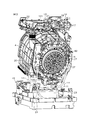
- FIG. 2 is a perspective view of the washing / drying machine 1 according to an embodiment of the present invention as viewed obliquely from the front, and shows the internal structure from which the housing 2 is removed.
- FIG. 3 is a perspective view of the washing / drying machine 1 as viewed obliquely from the rear, and shows the internal structure with the housing 2 removed.
- reference numeral 3 denotes a washing tub, and the washing tub 3 includes an outer tub 4 and a drum 5.
- the washing tub 3 is supported by an elastic support member 14 including a coil spring and a damper.
- a tank 11 is disposed below the washing tub 3.
- a filter unit 15 is disposed on the front right side of the tank 11, and the filter unit 15 is connected to the washing tub 3 and the tank 11 by a predetermined hose or pipe.
- a faucet 16 At the upper part of the washing tub 3, a faucet 16, a water supply valve 17 for controlling the supply of water from the faucet 16 to the water channel, a water inlet unit 18, and an ozone generator for generating ozone as a purification gas 19.
- a blower 21 for circulating air through the drying air passage 20 in the drying process, and a drying filter unit 22 for capturing foreign matters such as lint contained in the air circulated through the drying air passage 20 by the blower 21. Is provided.
- the water supply valve 17 is controlled, and the tap water supplied from the faucet 16 is stored in the washing tub 3. At that time, if the water passes through the detergent container 29 in the water inlet unit 18 and reaches the washing tub 3, the water in which the detergent is dissolved can be stored in the washing tub 3.
- the drum 5 is rotated by the DD motor 6. Further, the water in the washing tub 3 is pumped out by the circulation pump 25 via the filter unit 15, and the pumped water is guided to the upper rear surface of the outer tub 4 through the circulation water channel (second circulation water channel 57).
- a gas-liquid mixer 27 is interposed in the middle of the circulation channel, and in the gas-liquid mixer 27, ozone generated by the ozone generator 19 is mixed into water flowing from top to bottom.
- ozone is mixed into water, the water is purified by the strong oxidation and sterilization of ozone. That is, the water in the washing tub 3 is circulated in the washing process and is used for washing while being purified by mixing ozone into the circulated water.
- the protrusion 82 which protrudes back from the rear surface of the outer tank 4 is provided in the vicinity of the gas-liquid mixer 27, and when the outer tank 4 shakes and collides with a housing
- FIG. 4 is a diagram schematically showing a configuration centering on the water channel and the air channel of the washing / drying machine 1.
- the water tap 16 is connected to the inlet of the water supply valve 17.
- the water supply valve 17 has four outlets, and the outlet from which water is discharged can be switched.
- the first outlet 28 of the water supply valve 17 is connected to the water inlet unit 18.
- the water inlet unit 18 includes a two-branch water channel that divides the water supplied from the first outlet 28 into a water channel that leads to the water supply channel 32 and a water channel that leads to the priming water channel 33. Yes.
- the water supplied from the first outlet 28 to the water inlet unit 18 mainly flows through the priming water channel 33, the bath water pump 34, and the water channel 37 to the detergent container 29. And it flows in from the water supply path 30 to the washing tub 3 via the detergent storage chamber partitioned in the detergent container 29.
- a part of the water branched and flowing into the water supply channel 32 flows into the washing tub 3 from the upper part of the door 10 (see FIG. 1) provided on the front surface of the washing tub 3 through the inner surface of the door. ing.
- the second outlet 31 of the water supply valve 17 is also connected to the water inlet unit 18, and the water supplied from the second outlet 31 is washed from the water supply path 30 through the softener storage chamber partitioned in the detergent container 29. It flows into the water tank 3.
- the bath water pump 34 when the bath water pump 34 is driven, the remaining hot water in the bathtub 35 is pumped up and flows into the water inlet unit 18 from the water channel 37, passes through the detergent storage chamber of the detergent container 29, and passes from the water supply channel 30 to the washing tub 3. Supplied with.
- the third outlet 38 of the water supply valve 17 is connected to a predetermined position of the drying air passage 20 by a water passage 39.
- the fourth outlet 40 of the water supply valve 17 is connected to a predetermined position of the drying air passage 20 by a water passage 41.
- the third outlet 38 is a relatively small diameter outlet, and the fourth outlet 40 is a relatively large diameter outlet. For this reason, when the third outlet 38 is opened, a relatively small amount of water is supplied to the drying air passage 20 via the water passage 30.
- This water is brought into contact with hot and humid circulating air in the drying air passage 20 and contributes to heat exchange.
- the fourth outlet 40 When the fourth outlet 40 is opened, a relatively large amount of water is supplied to the drying air passage 20 through the water passage 41. This water contributes to washing away lint and other foreign matters contained in the circulating air rising in the dry air passage 20 and lint and other foreign matters adhering to the inner wall of the dry air passage 20.
- a drain port 42 is formed at the bottom bottom of the washing tub 3 (more specifically, the bottom bottom of the outer tub 4).
- An inflow port of the first drain valve 44 is connected to the drain port 42 through the water channel 43, and an outflow port of the first drain valve 44 is connected to the inlet 151 of the filter unit 15 through the water channel 45. .
- the water level in the washing tub 3 is detected by a water level sensor 47 based on a pressure change in the air hose 46 branched from the water channel 43 and extending upward.
- the filter unit 15 has a case 150, and a filter main body 83 for capturing foreign matter is provided in the case 150.
- the case 150 has a drain port 152, a first outflow port 153, and a second outflow port 154.
- the outlet of the second drain valve 48 is connected to the drain port 152, and the outlet of the second drain valve 48 is connected to the external drain hose 50 and the drain trap 51 via the water channel 49.
- the water in the washing tub 3 is drained from the drain port 42, the water channel 43, the first drain valve 44, the water channel 45, the filter unit 15, the drain port 152, The water is discharged to the drain trap 51 through the second drain valve 48, the water channel 49, and the external drain hose 50.
- One end (lower end) of the overflow water channel 52 joins the water channel 49.
- the other end (upper end) of the overflow water channel 52 communicates with an overflow port 53 provided in the outer tub 4.
- An air pressure adjusting hose 54 is connected between the middle part of the overflow water channel 52 in the vertical direction and the inlet 151 of the filter unit 15. By providing the hose 54, the pressure in the washing tub 3 is equal to the pressure on the inlet 151 side of the filter unit 15, and problems such as reverse flow of water in the filter unit 15 are prevented.
- One end of the first circulation water passage 55 is connected to the first outlet 153 of the filter unit 15, and the other end of the first circulation water passage 55 is connected to the suction port of the circulation pump 25.
- One end of a second circulation water channel 57 is connected to the discharge port of the circulation pump 25. The other end side of the second circulation water channel 57 extends upward to a position higher than the normal water level of water stored in the washing tub 3.
- a U-turn portion 26 that is U-turned downward from above is connected to the tip.
- the upper end of a venturi tube 58 as the gas-liquid mixer 27 is connected to the U-turn portion 26.
- One end (upper end) of the third circulating water channel 59 is connected to the lower end of the venturi pipe 58, and the other end (lower end) of the third circulating water channel 59 is connected to the lower back of the washing water tank 3 (outer tank 4).
- the venturi pipe 58 is provided with an air inlet 60, and the ozone generator 19 is connected to the air inlet 60 via an air tube 61.
- the ozone generator 19 When the ozone generator 19 is activated when water flows through the venturi pipe 58, the purification air containing ozone generated by the ozone generator 19 is supplied from the air inlet 60 through the air tube 61 to the venturi pipe 58. It flows in.
- the inflow principle is due to a pressure difference (negative pressure) caused by water flowing in the venturi tube 58.
- the circulated water is purified by the strong oxidizing power and sterilizing power of ozone, and washing in the washing tub 3 can be performed using the purified water.
- One end (upper end) of the water storage channel 62 is connected to the second outlet 154 of the filter unit 15, and the other end (lower end) of the water storage channel 62 is connected to the inlet of the water storage valve 63.
- the outlet of the water storage valve 63 is connected to the tank 11. For example, after the rinsing process is completed, when the first drain valve 44 is opened, the second drain valve 48 is closed, and the water storage valve 63 is opened in a state where the circulation pump 25 is stopped, the rinse accumulated in the washing tub 3.
- the water used for the drainage is drained by the gravity (natural fall) 42 ⁇ water channel 43 ⁇ first drain valve 44 ⁇ water channel 45 ⁇ It flows from the inlet 151 to the case 150 to the second outlet 154 to the water storage channel 62 to the water storage valve 63 to the tank 11. Thereby, the used water used by rinsing in the tank 11 can be stored as recycled water.
- An overflow port 64 is provided above the tank 11, and one end of a water channel 65 is connected to the overflow port 64, and the other end of the water channel 65 is joined in the middle of the overflow water channel 52. Therefore, when water is to be accumulated in the tank 11 in a predetermined amount or more, the water flows from the overflow port 64 ⁇ the water channel 65 ⁇ the overflow water channel 52 ⁇ the water channel 49 ⁇ the external drain hose 50 ⁇ the drain trap 51 to be discharged. Is done.
- the washing dryer 1 is provided with a drying air path 20 in order to perform a drying function.
- the drying air channel 20 is disposed outside the washing tub 3 (outer tub 4), sucks out air in the washing tub 3 from the lower back of the outer tub 4, and washes the air from the upper front side of the outer tub 4. It is an air passage for circulating air so as to flow into the water tank 3.
- the drying air path 20 includes a connection pipe 66, a filter blower unit 70 (including the blower 21 and the drying filter unit 22), and a connection pipe 67. As described with reference to FIG.
- a drying heater A124 and a drying heater B125 are provided in the air path leading from the filter blower unit 70 to the connection pipe 67, and the circulated air is heated.
- a semiconductor heater can be used as the drying heater.
- the air sucked out from the washing tub 3 is dehumidified. Further, foreign matters such as lint contained in the air circulating in the dry air passage 20 and foreign matters attached to the inner wall of the dry air passage 20 are washed away.
- the recycled water stored in the tank 11 is circulated so as to pass through the drying air passage 20.
- a suction port of a drying pump 23 is connected to the tank 11.
- One end of an air passage water supply passage 24 is connected to the discharge port of the drying pump 23, and the other end of the air passage water supply passage 24 is connected to a first position of the drying air passage 20.
- the water that has flowed down in the drying air passage 20 does not flow into the outer tub 4 and is discharged, for example, from the lower end as the second position in the drying air passage 20 and returned into the tank 11.
- a large amount of water is required for heat exchange performed in the drying air passage 20 and cleaning of foreign matters such as lint adhering to the inner wall of the drying air passage 20.
- the washer / dryer 1 the water required for heat exchange and cleaning of foreign substances is configured to recycle the used water stored in the tank 11, and therefore, a significant water saving can be realized.
- capacitance of the tank 11 can be made small and even if it provides the tank 11, it can be set as the structure by which the external appearance of a washing-drying machine does not become large.
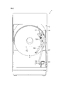
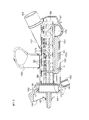
- FIG. 5 is a rear view of the washing / drying machine 1, and the first circulation water channel 55, the circulation pump 25, the second circulation water channel 57, the U-turn unit 26, the gas-liquid mixer 27 (Venturi tube 58), and the third circulation water channel 59. Only the elements necessary for the description are shown.
- the water after being filtered by the filter unit 15 is sucked through the first circulation channel 55 and discharged to the second circulation channel 57 by driving the circulation pump 25.
- the second circulation water channel 57 extends upward from below and guides the water to a level above the normal water level (indicated by a one-dot chain line 72) stored in the outer tub 4.
- the water is inverted from upward to downward by the U-turn portion 26 and flows into the gas-liquid mixer 27. Therefore, in the gas-liquid mixer 27, water flows from the top to the bottom.
- the gas-liquid mixer 27 is also disposed above the normal water level 72 of the water stored in the outer tub 4.
- the flow direction of the water discharged from the circulation pump 25 to the second circulation water channel 57 is reversed above the water level 72, so that the gas-liquid mixer 27 falls from above to below above the water level 72. Therefore, it flows down in the gas-liquid mixer 27 vigorously. Then, it passes through the third circulation water channel 59 and flows into the outer tub from the lower back of the outer tub 4.
- gas-liquid The mixer 27 can be disposed above the water level 72 of the water in the outer tub 4, and the gas-liquid mixer 27 can be disposed so as to extend in the vertical direction.
- the water flowing in the gas-liquid mixer 27 does not interfere with the flow of the water pressure due to the water level 72 in addition to the pumping force by the circulation pump 25, and flows down vigorously from above to below due to the action of gravity.
- a negative pressure is generated in the flow path, and the purified air containing ozone can be efficiently taken into the water.
- the water that has flowed down the gas-liquid mixer 27 is guided downward by the third circulation channel 59 and circulated from the lower back of the outer tank 4 into the outer tank 4.
- This circulated water is water in which fine bubbles of purifying air containing ozone are mixed, and when the water is returned from the lower side of the outer tub 4 to the inside of the washing tub 3, the purifying air contained in the water The fine bubbles move from the bottom to the top in the washing tub 3, and the clothes can be efficiently sterilized and deodorized in the washing tub 3.
- the third circulation water channel 59 may be configured to circulate water from the middle of the back surface of the outer tub 4 into the outer tub 4 without extending to the lower side of the outer tub 4.
- 61 is an air tube and the purification air containing ozone is supplied to the gas-liquid mixer 27 through the air tube 61.
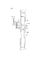
- FIG. 6 is a perspective view showing a specific configuration of the U-turn part 26 and the gas-liquid mixer 27.
- the U-turn part 26 and the gas-liquid mixer 27 are configured by combining and connecting resin pipes.
- the gas-liquid mixer 27 includes a venturi 73, an air intake 74, and a buffer chamber 75.
- FIG. 7 is a longitudinal sectional view showing the internal structure of the gas-liquid mixer 27.
- the gas-liquid mixer 27 includes the Venturi tube 58 as described above.
- the Venturi tube 58 extends in the up-down direction.
- the upper channel 78 has a large channel diameter at the upper side
- the throttle unit channel 77 has a channel size narrowed to the lower side below the upper channel 78
- the lower part of the throttle unit channel 77 are provided with a series of three types of flow passages, the lower flow passage 79 having a gradually increased flow passage diameter, in which the flow passage diameter changes.
- a small hole 80 for taking in air is formed in the inner wall of the throttle channel 77.
- the small hole 80 is connected to a buffer chamber 75 connected to the outer surface of the venturi tube 58. Air is supplied from the air intake 74 to the buffer chamber 75.
- a check valve 81 made of, for example, rubber is disposed at the inlet of the buffer chamber 75. The check valve 81 does not prevent air from flowing into the buffer chamber 75 from the air intake 74, but functions to prevent gas and liquid from flowing out of the buffer chamber 75 toward the air intake 74.
- the water that flows downward from the U-turn part 26 flows into the upper flow path 78 vigorously, and the flow velocity becomes faster in the throttle part flow path 77. For this reason, the negative pressure which can take in the air of buffer room 75 via air taking-in hole 80 is produced. Due to the negative pressure, the purification air containing ozone in the buffer chamber 75 enters the throttle channel 77 through the air intake hole 80 and is mixed into the flowing water as fine bubbles.
- the buffer chamber 75 is provided with a check valve 81.
- the ozone generator 19 does not become defective due to the water flowing backward through the air tube 61.
- steam in the washing tub 3 enters the third circulation water channel 59, enters the buffer chamber 75 through the air intake hole 80 through the venturi pipe 58, and further enters the ozone generator from the air inlet 74.
- the check valve 81 also prevents the backflow of steam during drying.
- the filter unit 15 is attached to the front right lower portion of the washing / drying machine 1.
- the filter unit 15 includes a case 150, an inflow port 151, a drainage port 152, a first outflow port 153, and a second outflow port 154.
- FIG. 8 is a perspective view of the filter unit 15 and shows a perspective view of the filter unit 15 when the washing / drying machine 1 is viewed obliquely from the front.
- the filter unit 15 includes a case 150, an inlet pipe 155, a drain pipe 156, outlet pipes 157 and 158, a front mounting plate 159, and mounting legs 160.
- Each of these members is formed of a resin (for example, polypropylene), and the front mounting plate 159 and mounting legs 160 that are integrally formed with the case 150, and a drain pipe formed separately.
- 156, the inflow pipe 155 and the outflow pipes 157 and 158 are liquid-tightly connected and integrated.
- the case 150 When the front mounting plate 159 and the mounting legs 160 are mounted on the casing 2 of the washing / drying machine 1, the case 150 has a longitudinal shape extending obliquely downward from the front toward the rear. A hole (not shown) is formed in the upper surface 150a of the case 150, and an inlet pipe 155 is attached to communicate with the hole. As described with reference to FIG. 4, the water channel 45 is connected to the inflow port 151 that is the opening end of the upper end of the inflow port pipe 155.
- the hose 54 described with reference to FIG. 4 is connected to the cylindrical protrusion 161 that is formed to protrude in the middle of the inflow pipe 155.
- the left and right side surfaces and the bottom surface of the case 150 are case-side bottom surfaces 150b that bulge downward in an arc shape without a boundary.
- the drain port pipe 156 protrudes laterally from the case side bottom surface 150 b in the direction intersecting the length direction of the case 150, more specifically in the direction orthogonal to the length direction, and the tip thereof becomes the drain port 152. ing.
- the drain port pipe 156 protrudes from the rear side in the length direction of the case 150 (the lower side of the case 150 extending obliquely).
- the outlet pipe 157 is bent at a right angle in the middle of the length direction, and the attachment position to the case 150 is the attachment position of the inlet pipe 155 and the drainage when viewed in the length direction of the case 150. It is an intermediate position with respect to the attachment position of the mouth pipe 156.
- the drain port pipe 157 is attached so as to protrude laterally from the side bottom surface 150 b of the case 150, and a distal end side that is bent by approximately 90 ° serves as a second outlet 154.
- an outlet pipe 158 is connected so as to branch from the outlet pipe 157, and the tip of the pipe 158 is a first outlet 153.
- the suction side of the second drain valve 48, the first circulation water channel 55, and the water storage water channel 62 are connected to the drain port 152, the first outlet port 153, and the second outlet port 154, respectively. .
- a filter insertion hole 162 is formed in the front mounting plate 159.
- the filter insertion opening 162 communicates with the internal space of the case 150.
- the filter main body 83 (see FIG. 9) is inserted into the case 150 from the filter insertion port 162, and the operation lid 85 is turned to the state shown in FIG. 8, so that the filter unit 15 can function normally. It becomes a state.
- ribs 113 projecting forward are provided on both lower sides of the front mounting plate 159 where the filter insertion ports 162 are formed, and a movable body (see FIG. 21) described later can be freely rotated on the ribs 113.
- An engagement hole 114 for attachment is formed.
- FIG. 9 is a perspective view showing a configuration of the filter main body 83.
- the filter main body 83 includes a basket 84 and an operation lid 85 as filtering members.
- the basket 84 is formed of a resin, the upper surface is opened, and a large number of filtration holes and filtration slits are arranged on the side surface and the bottom surface.
- FIG. 10 is a perspective view showing the configuration of the basket 84 alone with the operation lid 85 removed from the filter body 83.
- the filtration holes arranged in the basket 84 include a small filtration hole 86 having a hole size (maximum diameter) of a predetermined dimension or less and a relatively large large hole size.
- the filter hole 87 and the slit hole 89 defined between the rods 88 arranged in a comb shape are included.
- the small filtration holes 86 are arranged on a part of the front left side surface and the front bottom surface of the basket 84, and the surface on which the small filtration holes 86 are arranged is a reuse water filtration surface 90.
- the rear left side surface, rear surface, part of the bottom surface and part of the right side surface of the basket 84 in which the large filtration holes 87 are arranged, and the surface on which the plurality of rods 88 are provided and the slit holes 89 are defined It becomes the discharge water filtration surface 91.
- partitioning ribs 92 and 93 are formed at the boundary between the reused water filtering surface 90 and the discharged water filtering surface 91 so as to protrude from the outer surface of the basket 84.
- the front surface of the basket 84 is closed with a sealing wall 94, and an annular flange 95 projects from the periphery of the sealing wall 94 (see FIG. 10).
- an operation lid 85 is rotatably fitted to the flange 95 shown in FIG. Therefore, the operation lid 85 and the basket 84 can rotate with respect to each other.
- a seal ring 96 made of rubber or the like is provided on the inner peripheral surface of the operation lid 85.
- the basket 84 of the filter main body 83 is inserted into the case 150 from the filter insertion port 162 shown in FIG. 8, and the operation lid 85 is rotated after the insertion, whereby the seal ring is formed between the filter insertion port 162 and the operation lid 85.
- 96 is liquid-tightly sealed, and the attachment of the filter body 83 to the case 150 is completed.
- the shape of the inner wall of the case 150 is a specific shape so that the direction of the basket 84 is a predetermined direction.
- the basket 84 includes a rib 93 that protrudes downward from the bottom surface and extends in the front-rear direction (the length direction of the case 150).
- the rib 93 has a gap with the inner bottom surface 150 c of the case 150 d (mm) (d is not more than the size (maximum diameter) of the small filtration hole. ).
- a part 931 of the rib 93 serves to position the basket 84 in the case 150 by contacting the inner bottom surface 150 c of the case 150.
- the rib 93 includes a large filtration hole 87 and a slit hole 89 (FIG. 10) included in the drainage water filtration surface 91 existing on the near side in FIG.
- the water that flows out of the basket 84 and flows between the lower surface of the basket 84 and the inner bottom surface 150c of the case 150 into the inlet 157a of the outlet pipe 157 contains large foreign matter. In such a case, it acts to prevent the foreign matter from flowing into the inlet 157.
- the ribs 92 protruding from the outer surface side of the basket 84 form gaps between the case inner side surface and the inner bottom surface 150 c and the basket 84. It is prescribed to a predetermined dimension d (mm) (d is equal to or smaller than the size (maximum diameter) of the small filtration hole). For this reason, for example, water that has flowed out of the basket 84 through the large filtration hole 87 formed on the back side surface of the basket 84 passes through the gap between the basket 84 and the inner side surface or inner bottom surface 150c of the case 150 and moves forward. When a relatively large foreign matter is contained in the flowing water when the flow and the outflow pipe 157 are tried to flow, it serves to prevent the foreign matter from entering the outflow pipe 157. .
- the ribs 92 and 93 are formed so as to surround the periphery of the reused water filtration surface 90 in which the small filtration hole 86 is formed, and the ribs 92 and 93 are opposed to the inner surface of the case 150 and are reused.
- a gap larger than the size of the small filtration hole 86 is not generated around the use water filtration surface 90.
- the water that has entered the basket 84 is filtered through the reused water filtration surface 90 in which the small filtration holes 86 are formed, and the water and the ribs 92 and 93 that pass through the reused water filtration surface 90 and the case 150.
- the water passing through the gap with the inner surface of the gas flows into the outlet pipe 150. Therefore, the water flowing into the outlet pipe 157 does not include foreign matters larger than the small filtration hole 86.
- the size (maximum diameter) of the small filtration hole 86 is made smaller than the inner diameter ⁇ of the throttle channel 77 of the venturi pipe 58 of the gas-liquid mixer 27, so that the water flowing through the venturi pipe 58 No foreign substance larger than the inner diameter ⁇ of the throttle channel 77 is present, and the foreign substance is clogged in the throttle channel 77 having a narrowed flow diameter, so that the flow of water flowing through the venturi pipe 58 decreases or stops. There is nothing.
- the case 150 of the filter unit 15 has a longitudinal shape extending obliquely downward from the front to the rear, and the basket 84 of the filter main body 83 is accommodated therein. .
- the outlet pipe 157 is attached to the front side of the drain outlet pipe 156, that is, relative to the upper side of the case 150. Accordingly, as shown in FIGS.
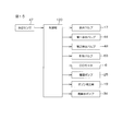
- FIG. 15 is a block diagram for explaining the configuration of the electrical control circuit of the washing / drying machine 1.
- the block diagram of FIG. 15 shows only elements that are necessary when the washing / drying machine 1 executes the washing process and the rinsing process.
- the control unit 120 is a control center of the washing / drying machine 1 and is configured by a microcomputer.
- the control unit 120 is included in the electrical component 12 (see FIG. 1).
- the detected water level of the water level sensor 47 (see FIG. 4) is input to the control unit 120.
- a water supply valve 17, a first drain valve 44, a second drain valve 48, a water storage valve 63, a DD motor 6, a circulation pump 25, an ozone generator 19, and a bath water pump 34 are connected to the control unit 120.
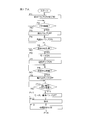
- the control unit 120 controls the operation or driving of these connected components. ⁇ Control operation of washing process and rinsing process> FIG.
- 16 is a flowchart for explaining the contents of the operation control in the washing process and the rinsing process of the washing / drying machine 1. With reference to the flowchart of FIG. 16, the control operation of the washing process and the rinsing process of the washing / drying machine 1 will be described.
- the washing process is divided into a washing process, a rinsing process, and a rinsing process.
- This control operation is performed when washing and rinsing are performed using tap water.
- water is supplied (step S1).
- the start of water supply starts when the first outlet 28 (see FIG. 4) of the water supply valve 17 is opened.
- the water supply is started, the water that has entered the water inlet unit 18 from the first outlet 28 passes through the priming water channel 33, the bath water pump 34, and the water channel 37, and dissolves the detergent contained in the detergent container 29 while passing through the water channel 30. It flows into the washing tub 3 through.
- the water level of the washing tub 3 (outer tub 4) is monitored by a water level sensor 47 and is supplied to the control unit 120.
- the control unit 120 opens the first drain valve 44 and closes the second drain valve 48 and the water storage valve 63. Therefore, the water supplied to the washing tub 3 also flows into the drainage port 152, the filter unit 15, the first circulation water channel 55, the water storage water channel 62, and the water channel 45. These waters are supplied to the second drain valve 48, the circulation pump. 25.
- the water is stored in the washing tank 3 after being blocked by the water storage valve 63 and filling these water channels with water.
- control unit 120 may close the first drain valve 44 at the start of water supply.
- the water supplied to the washing tub 3 flows out from the drain outlet 42 into the water channel 43, but is stopped by the first drain valve 44, and the water is stored in the washing tub 3.
- the control unit 120 determines whether or not the detected water level of the water level sensor 47 has reached a preset water level (step S2), and when it reaches the set water level, closes the water supply valve 17 and stops water supply. (Step S3).
- the DD motor 6 is driven to alternately reverse the drum 5 to the right rotation and the left rotation, and the circulation pump 25 is driven (step S4).
- the water in the washing tub 3 flows from the washing tub 3 ⁇ the drain port 42 ⁇ the water channel 43 ⁇ the first drain valve 44 ⁇ the water channel 45 ⁇ the filter unit 15 ⁇ the first circulation channel 55 ⁇ the circulation pump 25 ⁇ the second circulation channel 57.
- U-turn part 26 ⁇ Venturi pipe 58 ⁇ first circulation water channel 59 ⁇ circulates to the washing tub 3
- the detergent flowing into the washing tub 3 together with water from the detergent container 29 dissolves in water smoothly in a short time.
- the concentration of the detergent water in which the detergent is dissolved can be made uniform in a short time.
- the detergent When the water used for washing is circulated, the detergent can be quickly dissolved in water as described above, and the detergent concentration of the detergent water can be made uniform. In order to pass through, the underwater waste is captured by the filter unit 15. Therefore, the dust in the detergent water is removed by the circulation, and the detergent water can be purified. Then, it is determined whether or not a preset time, for example, 15 minutes has elapsed as the washing time (step S5). When the preset time, for example, 15 minutes has elapsed, the DD motor 6 is driven. Is stopped, and the driving of the circulation pump 25 is also stopped (step S6). Then, the second drain valve 44 is opened, and the detergent water in the washing tub 3 is drained to the drain trap 51.
- a preset time for example, 15 minutes has elapsed
- the DD motor 6 is driven to rotate the drum 5 in one direction at high speed, and the clothes stored in the drum 5 are dehydrated.
- This dehydration is called intermediate dehydration, and is performed for a short time, for example, about 1 minute (step S7).
- a feature of the washing process is that the detergent water stored in the washing tub 3 is circulated by the circulation pump 25, but the ozone generator 19 is not activated. That is, in the washing process, the detergent water stored in the washing tub 3 is only circulated, and the cleaning air containing ozone is not mixed into the circulated detergent water.
- the process proceeds to the first rinsing process.
- the first rinsing step the second drain valve 48 is closed, the first outlet 28 of the water supply valve 17 is opened, and water supply is started (step S8). Water supplied from the first outlet of the water supply valve 17 flows into the washing tub 3 through the detergent container 29 and the water supply passage 30 of the water inlet unit 18.
- the detergent contained in the detergent container 29 is poured into the washing tub 3 at the time of water supply in the washing process, and since no detergent remains, only the tap water is supplied to the washing tub 3. Then, based on the detected water level of the water level sensor 47, it is determined whether or not the water level stored in the washing tub 3 has reached a preset set water level (step S9). 17 is closed and water supply is stopped (step S10).
- the DD motor 6 is driven, and the drum 5 is alternately reversed to the right rotation and the left rotation.
- the circulation pump 25 is driven, and the water (rinse water) in the washing tub 3 is circulated through the circulation channels (42, 43, 44, 45, 15, 55, 25, 57, 26, 58, 59). Is done. Even during this circulation, since the circulating water is filtered by the filter unit 15, if the circulated water contains lint or other waste, the waste is captured by the filter unit 15 and the waste is removed from the water by the circulation. Water purification is performed.
- the ozone generator 19 is activated (step S12).
- ozone is generated.
- the ozone generated by the ozone generator 19 is mixed by negative pressure into the circulating water passing through the air tube 61 and from the air inlet 60 into the venturi pipe 58. Therefore, the water circulated to the washing tub 3 includes air containing ozone as purification air. As a result, residual detergent components remaining in the rinse water are oxidized and removed by the strong oxidizing power and sterilizing power of ozone.
- One rinsing step is set to a relatively short time of, for example, 3 minutes in this embodiment. It is determined whether or not 3 minutes, which is the time of rinsing 1, has elapsed (step S13). When 3 minutes have elapsed, the driving of the DD motor 6 and the circulation pump 25 is stopped, and the operation of the ozone generator 19 is activated. Stopped (step S14). Then, the second drain valve 48 is opened and the rinse water in the washing tub 3 is drained to the drain trap 51. After the drainage is finished, the DD motor 6 is driven to rotate the drum 5 in one direction at a high speed. Intermediate dehydration of the clothes in 5 is performed (step S15). The intermediate dehydration time is set to a relatively short time, for example, about 1 minute.
- the process proceeds from the first rinse step to the second rinse step.
- the second drain valve 48 is closed, the first outlet of the water supply valve 17 is opened, and the supply of tap water is started (step S16).
- the water level detected by the water level sensor 47 it is determined whether or not the water level in the washing tub 3 has reached a predetermined set water level (step S17).
- the water supply valve 17 is closed.
- the water supply is stopped (step S18).
- the DD motor 6 is driven, the drum 5 is driven to reversely rotate clockwise and counterclockwise, the circulation pump 25 is driven, and the rinse water accumulated in the washing tub 3 is circulated (step S19). .
- the ozone generator 19 is activated (step S20).
- air containing ozone is mixed into the circulated water in the gas-liquid mixer 27. Therefore, the rinse water in the washing tub 3 becomes ozone-containing water having a strong oxidizing action and a sterilizing action, removing germs adhering to the clothes, decomposing odorous components, and oils and fats of clothes that cannot be removed with a detergent. System dirt can be decomposed.
- the two rinse steps are set to 12 minutes, for example. That is, two rinsing steps are performed for a relatively long time of 12 minutes as compared with one rinsing step.
- ozone as the purification air mixed in the rinsing water eliminates germs adhering to the laundry, decomposes odorous components, and decomposes fat-based soil that cannot be removed by the detergent attached to the laundry. Good rinsing is performed.
- step S21 When 12 minutes have passed (step S21), the operation of the ozone generator 19 is stopped (step S22). Then, when the setting to input the softening agent is made, the softening agent input processing is performed (step S23).
- the softener When the softener is introduced, the second outlet 31 (see FIG. 4) of the water supply valve 17 is opened, and the tap water is supplied to the water supply passage 30 via the softener storage chamber partitioned in the detergent container 29 of the water inlet unit 18. Is carried out by flowing into the washing tub 3.
- the softening agent flows along with the water and flows into the washing tub 3.
- step S24 By supplying a predetermined amount of water, for example, controlling the time for opening the water supply valve 17 according to the time, the softener charging process is completed. Thereafter, the inversion drive of the drum 5 and the circulation of the water in the washing tub 3 are continued for 2 minutes thereafter (step S24). When 2 minutes have elapsed, the DD motor 6 is stopped and the circulation pump 25 is driven. Is also stopped (step S25).
- the second rinsing process is completed, the second drain valve 48 is opened, and the rinse water in the washing tub 3 is drained to the drain trap 51 (step S26).
- the DD motor 6 is driven, the drum 5 is rotated in one direction at high speed, and final dehydration is performed (step S26).
- the time of one rinsing process and the time of two rinsing processes in the above-described embodiment are merely examples, and may be set to a time other than this example. However, it is one of the features of the present invention that the time of the two rinsing steps is longer than the time of the rinsing one step. The rinse is realized.
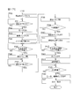
- FIG. 17A, FIG. 17B, and FIG. 17C are flowcharts showing an example of the control operation of the washing / drying machine 1. This flowchart shows the control contents when the washing process and the rinsing process are performed using bath water.
- the rinsing process includes one rinsing process and two rinsing processes, but the rinsing process may include one rinsing process, two rinsing processes, three rinsing processes, and three or more. it can.
- the control operation will be described in accordance with the flow of FIGS. 17A, 17B, and 17C and with reference to FIG.
- the first outlet 28 of the water supply valve 17 is opened for a predetermined time, for example, 15 seconds (steps P1, P2, and P3).
- the first outlet 28 of the water supply valve 17 is opened, tap water is supplied from the first outlet 28 to the water inlet unit 18, and the water flows through the priming water channel 33 to the bath water pump 34. Via the water channel 37, it passes through the detergent container 29 of the water inlet unit 18, flows into the washing tub 3 through the water supply channel 30.
- the reason for opening the first outlet 28 of the water supply valve 17 for a predetermined short time is to supply priming water to the bath water pump 34.
- Step P4 the bath water pump 34 is started to be driven instead.
- the bath water pump 34 By driving the bath water pump 34, the bath water stored in the bathtub 35 is pumped out through the bath water hose 36 and flows from the water channel 37 to the detergent container 29. Then, the bath water flows from the water supply channel 30 into the washing tub 3 along with the detergent contained in the detergent storage chamber in the detergent container 29.
- the first drain valve 44 is opened, the second drain valve 48 is closed, and the water storage valve 63 is closed. Since the first drain valve 44 is opened and the second drain valve 48 is closed, the bath water flowing into the washing tub 3 initially flows from the drain port 42 into the water channels 43 and 45, but these water channels 43. After that, the bath water does not go out of the washing tub 3 and the inflowing bath water accumulates in the washing tub 3.
- the water level in the washing tub 3 is detected by a water level sensor 47.
- a water level sensor 47 When it is determined that the detected water level of the water level sensor 47 has reached a predetermined set water level (washing start water level) (step P5), the DD motor 6 is driven and the drum 5 is alternately reversed to the right and left rotations. (Step P6). Further, the circulation pump 25 is driven (step P7), and the bath water stored in the washing tub 3 is drained 42 ⁇ water channel 43 ⁇ first drain valve 44 ⁇ water channel 45 ⁇ filter unit 15 ⁇ first circulation water channel 55 ⁇ circulation. The pump 25 is circulated to the second circulation water channel 57 ⁇ the U-turn portion 26 ⁇ the venturi pipe 58 ⁇ the third circulation water channel 59 ⁇ the washing water tank 3. By this circulation, the detergent stored in the detergent container 29 poured together with the bath water quickly dissolves in the bath water and becomes the detergent water used in the washing process.
- step P8 When the water level sensor 47 detects that the water level in the washing tub 3 has reached the set water level (full water level) for washing (step P8), the driving of the bath water pump 34 is stopped (step P9). The supply of bath water to the water tank 3 is stopped, and washing is performed with the stored detergent water. Then, it is determined whether or not a predetermined washing time, for example, 15 minutes has elapsed (step P10). When 15 minutes have elapsed, the driving of the DD motor 6 and the circulation pump 25 is stopped (step P11). In this way, during washing, the drum 15 is alternately reversed clockwise and counterclockwise by the DD motor 6, and the water in the washing tub 3 is circulated by the circulation pump 25. Therefore, the detergent water in the washing tub 3 is well stirred by circulation, the detergent concentration becomes uniform, and washing with good washing performance can be performed.
- a predetermined washing time for example, 15 minutes has elapsed
- the cleaning water that circulates is not mixed with the detergent water that circulates, and the detergent components are not oxidized by ozone and the washing ability is not reduced.
- the second drain valve 48 is opened to drain water (step P12). After the detergent water in the washing tub 3 has been discharged, the DD motor 6 is driven, and the drum 5 is rotated at a high speed in one direction to perform intermediate dehydration (step P13).
- the intermediate dehydration performed in Step P13 is made different in time depending on whether one rinsing process is performed using bath water or tap water. Specifically, when one rinsing process is performed using tap water, the intermediate dehydration is performed for one minute (see step S7 in FIG. 16). If used, intermediate dehydration is performed for 4 minutes. When one rinsing process is performed with bath water, the time for intermediate dehydration is lengthened because the detergent water contained in the laundry is sufficiently squeezed out by dehydration, and when bath water is supplied in one rinsing process, it comes out of the laundry This is because the residual detergent components are reduced and the bath water is sterilized well.
- the bath water pump 34 starts to be driven (step P14), and when the water level sensor 47 detects that the water level in the washing tub 3 has reached a predetermined rinsing water level (step P15), the DD motor 6 Is driven and the drum 5 is alternately rotated to the right and left (step P16), and the circulation pump 25 is driven to circulate the water stored in the washing tub 3 (step P17).
- the ozone generator 19 is activated (step P18). If the ozone generator 19 is activated when the circulation pump 25 is driven and water is circulated, the ozone generated by the ozone generator 19 passes through the air tube 61 from the air inlet 60 to the venturi tube. It is taken into 58 by negative pressure and mixed into circulating water. Thereafter, when the detected water level of the water level sensor 47 reaches the water injection rinse water level that is higher than the accumulated rinse water level (the water injection rinse water level is, for example, the water level overflowing from the overflow port 53) (step P19), the second drainage.
- the water injection rinse water level is, for example, the water level overflowing from the overflow port 53
- a part of the bath water stored in the washing tub 3 by opening the valve 48 is drained to the drain trap 51 (step P20), and the water level in the washing tub 3 is reduced to the rinsing water level (step P21). 2
- the drain valve 48 is closed (step P22).
- step P23 bath water continues to be supplied by the bath water pump 34, so that the water level in the washing tub 3 rises again. Then, it is determined whether or not a predetermined time, for example, 2 minutes has elapsed (step P23). Until two minutes have elapsed, the processes of steps P19 to P22 are repeated. That is, the water is accumulated up to the water injection rinse level higher than the set water level, and the operation of partially draining the water to the set water level is repeated. Thereby, the residual detergent component in the stored bath water can be diluted and reduced.
- a predetermined time for example, 2 minutes has elapsed
- step P24 When it is determined in step P23 that 2 minutes have elapsed, the driving of the bath water pump 34 is stopped (step P24), the second drain valve 48 is opened again, and the water level in the washing tub 3 is reduced to the rinsing water level. Sometimes the second drain valve 48 is closed (step P25). In this way, in Steps P19 to P25, bath water is supplied into the washing tub 3 and accumulated until the water level becomes a rinsing water level higher than the rinsing water level, and a part of the accumulated bath water is drained. Again, the water level is increased to the rinsing water level, and then a part of the bath water is drained and stored to obtain a rinsing water level. By this treatment, the residual detergent components dissolved in the bath water stored in the washing tub 3 can be reduced.
- step P26 it is determined whether, for example, 15 minutes have passed as the time for one rinsing process. When 15 minutes have elapsed, the driving of the DD motor 6 and the circulation pump 25 is stopped, and the ozone generator 19 The operation is stopped (step P27).
- the time for one rinsing step is not less than 3 minutes and not more than 15 minutes, and may be shorter than 15 minutes.
- the second drain valve 48 is opened, and the water in the washing tub 3 is drained to the drain trap 51 (step P28).
- the DD motor 6 is driven, the drum 5 is rotated at a high speed in one direction, and intermediate dehydration is performed, for example, for 2 minutes (step P29).
- the time for intermediate dehydration performed at the end of one rinsing process is shorter than the time for intermediate dehydration after the washing process performed in step P13. This is because the amount of residual detergent component contained in the laundry after the first rinsing process is less than the residual detergent component contained in the laundry after washing. This is because priority was given to shortening the overall time.
- step P30 the process proceeds to the second rinsing step, the second drain valve 48 is closed, and the bath water pump 34 is started to be driven (step P30).
- step P31 the DD motor 6 is driven and the drum 5 is alternately reversed to the right and left rotations (Ste P32).
- the circulation pump 25 is driven (step P33), and the circulation of the bath water stored in the washing tub 3 is started.
- the ozone generator 19 is operated (step P34), ozone is mixed into the circulating bath water, and the bath water is purified.
- step P35 When the bath water pump 34 is continuously driven and the water level of the bath water stored in the washing tub 3 reaches the rinsing water level (step P35), the second drain valve 48 is opened (step P36), and the washing is performed.
- step P37 When a part of the bath water stored in the water tank 3 is drained and the water level is reduced to the rinse water level (step P37), the second drain valve 48 is closed (step P38). Thereafter, it is determined whether or not a predetermined time, for example, 1 minute has elapsed (step P39). Until one minute has elapsed, the processes of steps P35 to P38 are repeated.
- the water is accumulated up to the water injection rinse level higher than the set water level, and the operation of partially draining the water to the set water level is repeated. Thereby, the residual detergent component in the accumulated bath water can be reduced.
- the reason why the predetermined time is shorter than that in Step P23 is that the rinsing two steps have less residual detergent components than the rinsing one step and that the rinsing time is shortened. .
- step P39 When it is determined in step P39 that 1 minute has elapsed, the driving of the bath water pump 34 is stopped (step P40), the second drain valve 48 is opened, and the water level of the washing tub 3 is accumulated to the rinse water level (set water level). If it falls, the 2nd drainage valve 48 will be closed (step P41).
- the processing of Steps P35 to P41 is the same as the processing of Steps P19 to P25 in one rinsing process.
- the bath water is excessively stored in the washing tub 3 and a part thereof is drained twice and dissolved in the bath water. It is carried out in order to discharge and dilute the discharged detergent components by drainage.
- step P42 the operation of the ozone generator 19 is stopped (step P43).
- the flowchart of FIG. 17C is a control flow diagram for performing a softener charging process at the end of the two rinsing steps. Before the softener is added, the operation of the ozone generator 19 is stopped. Then, a softener charging process is performed (step P44).
- the softener charging process is performed by opening the second outlet 31 of the water supply valve 17 and pouring tap water into the softener storage chamber defined in the detergent container 29 in the water inlet unit 18 and supplying the softener together with tap water to the water supply channel. This is a process of flowing through the washing tub 3 through 30.
- the time for opening the second outlet 37 of the water supply valve 17, that is, the time for supplying tap water, is a predetermined time (for example, about 30 seconds).
- step P45 when it is determined that the drum 5 is reversed in the washing tub 3 and the time for which the softening agent charged by circulating the water by the circulation pump 25 reaches the laundry uniformly, for example, 2 minutes has passed (step P45). Then, the driving of the DD motor 6 and the circulation pump 25 is stopped (step P46). Then, the second drain valve 48 is opened and the water in the washing tub 3 is drained. Thereafter, the DD motor 6 is driven to rotate the drum 5 in one direction at high speed, and final dehydration is performed (step P47).
- the residual detergent component contained in the laundry is controlled to be as small as possible, so the ozone generated by the ozone generator 19 is included.
- the purification air is mixed in the bath water, there is no problem that most of the ozone is consumed by the residual detergent components, and the bath water can be well sterilized by ozone and can be rinsed with clean rinse water.
- germs and odorous components adhering to the clothing can be decomposed by ozone, and rinsing with a good finish can be performed.
Landscapes
- Engineering & Computer Science (AREA)
- Textile Engineering (AREA)
- Detail Structures Of Washing Machines And Dryers (AREA)
- Accessory Of Washing/Drying Machine, Commercial Washing/Drying Machine, Other Washing/Drying Machine (AREA)
- Control Of Washing Machine And Dryer (AREA)
Abstract
Description
特許文献1に記載の洗濯機は、貯水槽を備え、貯水槽に溜められた水をオゾンを用いて浄化する構成を備えている。
また、少ないすすぎ回数で衣類の汚れや洗剤成分をすすぎ落とすことができるすすぎ方法およびそのすすぎ方法を実行する洗濯機を、本願出願人は提案した。(特許文献2参照)
一方、洗濯に使用した後の水ではなく、洗濯中に、洗濯に使用している水を浄化しながら洗濯動作を行うことにより、浄化された水によってより良好な洗濯を行えるような洗濯機が望まれている。
この発明は、このような背景のもとになされたもので、風呂水をすすぎに使用することができ、しかも良好なすすぎが行える洗濯機を提供することを主たる目的とする。
この発明は、さらに、すすぎ処理が良好に行える洗濯機を提供することを他の目的とする。
この発明の洗濯機は、前記洗濯水槽に洗剤が溶けた洗剤水を溜めて洗い工程を行い、その後すすぎ工程を行う洗濯機であり、前記風呂水浄化制御手段は、前記すすぎ工程においてのみ機能することが好ましい。
この発明の洗濯機は、すすぎ工程において、前記風呂水ポンプを駆動して風呂水を前記洗濯水槽へ供給するとき、風呂水の供給に対して、洗濯水槽の水を排水するための排水バルブを所定の対応関係で開閉させる給排水制御手段を有していてもよい。
前記風呂水浄化制御手段が機能する前記すすぎ工程には、複数のすすぎ工程が含まれており、先行して行われるすすぎ工程における風呂水給水時間は、後続して行われるすすぎ工程における風呂水給水時間よりも長くされていてもよい。
また、洗い工程の後、中間脱水工程が行われて、すすぎ工程へと進む場合において、すすぎ工程が風呂水を用いて行われる場合は、中間脱水工程の脱水時間が長くされてもよい。中間脱水工程の脱水時間が長いと、洗濯物に含まれる洗剤水が十分に除去されるから、すすぎ工程において風呂水を供給したとき、残留洗剤成分が少なくなる。すすぎ水としての風呂水に浄化用空気を混入して浄化する場合、洗い工程で使用した洗剤成分が残留洗剤成分として多く残っていると、浄化用空気は残留洗剤成分の除去に費やされ、風呂水に含まれる雑菌等の除去を満足に行えない可能性がある。この構成によれば、洗い工程で使用した洗剤水を、中間脱水工程の脱水時間を長くすることによって十分に少なくでき、すすぎ工程において風呂水を満足に浄化することができる。
よって、すすぎ工程において風呂水浄化制御手段が機能すると、風呂水は良好に浄化される。
また、すすぎ工程を複数のすすぎ工程に分けることによって、効率良く洗濯物のすすぎを行うことができる。より具体的には、すすぎ工程を、たとえばすすぎ工程1およびすすぎ工程2に分けた場合、すすぎ工程1では、すすがれる洗濯物には洗い工程で用いられた洗剤水が残存しており、すすぎ水中の残留洗剤成分は相対的に多いと考えられる。そこで、風呂水の給水時間を相対的に長くして、残留洗剤成分の希釈化を行う。
以上説明したように、この発明によれば、すすぎ工程において、風呂水を用いて良好なすすぎ処理を行うことができる。
3 洗濯水槽
4 外槽
5 ドラム
6 DDモータ
15 フィルタユニット
17 給水バルブ
19 オゾン発生器
25 循環ポンプ
26 Uターン部
27 気液混合器
44 第1排水バルブ
48 第2排水バルブ
57 第2循環水路
58 ベンチュリー管
59 第3循環水路
77 絞り部流路
81 逆止弁
83 フィルタ本体
120 制御部
150 ケース
<洗濯乾燥機の構成および動作の概要>
図1は、この発明の一実施形態に係る洗濯乾燥機1の縦断面右側面図である。洗濯乾燥機1は、筐体(ハウジング)2内に斜めに配置された洗濯水槽3を備えている。洗濯水槽3には、洗濯時に水を溜めるための外槽4と、外槽4内に回転自在に収容されたドラム5とが含まれている。ドラム5は、外槽4の後方に備えられたDDモータ6によって回転軸7を中心に回転される。回転軸7は、前方に向かって斜め上方へ延びており、いわゆる斜めドラム構造をしている。ドラム5の出入口8および外槽4の出入口9は、筐体2に取り付けられたドア10によって開閉される。ドア10が開けられ、出入口8、9を通ってドラム5内への衣類(洗濯物)の出し入れがされる。
筐体2内の下方前方部には、主制御基板を含む電装部品12が設けられ、また、上方前方部には表示および操作用の電装部品13が備えられている。下方の電装部品12には、基板温度センサ123が含まれている。
図2は、この発明の一実施形態に係る洗濯乾燥機1を斜め前方から見た斜視図であり、筐体2が取り外された内部構造が示されている。また、図3は、洗濯乾燥機1を斜め後方から見た斜視図であり、筐体2が取り外された内部構造が示されている。
水バルブ17により水栓16から供給される水道水を、必要に応じて乾燥風路20へ供給する水路も備えられている。
以上が洗濯乾燥機1の構成および動作の概要である。次に、図4を参照して、洗濯乾燥機1の水路および風路を中心とする全体構成についてより詳細に説明をする。
<洗濯乾燥機の水路および風路の構成>
図4は、洗濯乾燥機1の水路および風路を中心とする構成を図解的に示す図である。
給水バルブ17の第3出口38は水路39によって乾燥風路20の所定位置に接続されている。また、給水バルブ17の第4出口40は水路41によって乾燥風路20の所定位置に接続されている。第3出口38は相対的に小径の出口であり、第4出口40は相対的に大径の出口である。このため、第3出口38が開かれると、相対的に少量の水が水路30を経由して乾燥風路20に供給される。この水は、乾燥風路20内で高温多湿の循環空気と接触され熱交換に寄与する。第4出口40が開かれると、水路41を介して乾燥風路20に相対的に多量の水が供給される。この水は、乾燥風路20内を上昇してくる循環空気に含まれるリントその他の異物や、乾燥風路20の内壁に付着したリントその他の異物を洗い流すのに寄与する。
フィルタユニット15の第1流出口153には第1循環水路55の一端が接続され、第1循環水路55の他端は循環ポンプ25の吸い込み口に接続されている。循環ポンプ25の吐出口には第2循環水路57の一端が接続されている。第2循環水路57の他端側は、洗濯水槽3内に溜められる水の通常の水位よりも高い位置まで上方へ延びている。そして、その先には、上から下向きにUターンしたUターン部26が接続されている。そしてUターン部26には気液混合器27としてのベンチュリー管58の上端が接続されている。ベンチュリー管58の下端には第3循環水路59の一端(上端)が接続され、第3循環水
路59の他端(下端)は洗濯水槽3(外槽4)の背面下方に接続されている。
流入口151→ケース150→第2流出口154→貯水用水路62→貯水バルブ63→タンク11へと流れる。これにより、タンク11内にすすぎで使用した既使用水を、リサイクル水として貯留することができる。
洗濯乾燥機1には、乾燥機能を行うために、乾燥風路20が備えられている。乾燥風路20は、洗濯水槽3(外槽4)の外側に配置され、外槽4の背面下方部から洗濯水槽3内の空気を吸い出し、その空気を外槽4の前方側上方部から洗濯水槽3内へ流入させるように空気を循環させるための風路である。乾燥風路20には、接続パイプ66、フィルタブロアユニット70(ブロア21および乾燥用フィルタユニット22が含まれる)および接続パイプ67が含まれている。フィルタブロアユニット70から接続パイプ67へつながる風路内には、図1で説明したように、乾燥ヒータA124および乾燥ヒータB125(図示せず)が備えられており、循環される空気が加熱される。乾燥ヒータは、たとえば半導体ヒータを用いることができる。
タンク11には乾燥用ポンプ23の吸い込み口が接続されている。乾燥用ポンプ23の吐出口には風路水供給路24の一端が接続され、風路水供給路24の他端は乾燥風路20の第1位置に接続されている。乾燥工程において、乾燥用ポンプ23が駆動されると、風路水供給路24を介して乾燥風路20の第1位置から乾燥風路20内へ水が供給される。供給される水は、上述したように、乾燥風路20内を下方から上方へと循環する空気と熱交換するとともに、空気中のリントなどの異物を洗い流し、かつ、乾燥風路20内の内壁に付着しようとする異物も洗い流す。そして、乾燥風路20内を下方へ流れ落ちた水は、リントなどの異物を伴って外槽4の下方から排水口42を通り、水路43→第1排水バルブ44→水路45→フィルタユニット15へと流れる。そしてフィルタユニット15において、リント等の異物は捕獲されて除去され、異物が除去された後の水は第2流出口154から貯水用水路62および貯水バルブ63を通ってタンク11内へ戻る。
乾燥工程では、乾燥風路20内で行う熱交換および乾燥風路20の内壁に付着するリント等の異物の洗浄のために多量の水が必要になる。この洗濯乾燥機1によれば、熱交換および異物の洗浄に必要な水は、タンク11に溜めた既使用水をリサイクルする構成としているため、極めて大幅な節水を実現できる。また、タンク11の水を循環させる構成であるから、タンク11の容量を小さくでき、タンク11を設けても、洗濯乾燥機の外観は大きくならない構成とすることができる。
<循環水路の構造>
図5は、洗濯乾燥機1の背面図で、第1循環水路55、循環ポンプ25、第2循環水路57、Uターン部26、気液混合器27(ベンチュリー管58)および第3循環水路59を含む循環水路構造を説明するための図で、説明に必要な要素のみが示されている。
取り込むことができる。
なお、61はエアーチューブで、エアーチューブ61を通して気液混合器27へオゾンを含む浄化用空気が供給される。
<Uターン部および気液混合器の構成>
図6は、Uターン部26および気液混合器27の具体的な構成を示す斜視図である。Uターン部26および気液混合器27は、この実施形態では、樹脂パイプが組み合わされ、連結されることにより構成されている。気液混合器27にはベンチュリー管73、空気取入口74およびバッファ室75が含まれている。
<フィルタユニットの構成>
次に、フィルタユニット15の構成について説明をする。
図8は、フィルタユニット15の斜視図であり、洗濯乾燥機1を斜め前方から見たときのフィルタユニット15の斜視図が示されている。
排水口用パイプ156は、ケース150の長さ方向に交差方向、より具体的には長さ方向に直交方向に、ケース側底面150bから側方へ突出しており、その先端が排水口152となっている。排水口用パイプ156は、ケース150の長さ方向奥側(斜めに延びたケース150の下方側)から突出している。
さらに、正面取付板159のフィルタ挿入口162が形成された位置の下方両側に、前方へ突出するリブ113が設けられ、このリブ113に後述する可動体(図21を参照)を回動自在に取り付けるための係合孔114が形成されている。
図10は、フィルタ本体83から操作蓋85を取り外したバスケット84単体の構成を示す斜視図である。
図10に示すフランジ95に対して、図9に示すように操作蓋85が回転自在に嵌められている。よって、操作蓋85とバスケット84とは互いに回転し得る。操作蓋85の奥側周面にはゴム等で構成されたシールリング96が備えられている。フィルタ本体83のバスケット84が図8に示すフィルタ挿入口162からケース150内へ挿入され、挿入後に操作蓋85が回動されることによって、フィルタ挿入口162と操作蓋85との間がシールリング96によって液密的に封止され、フィルタ本体83のケース150への取り付けが完成する。なお、ケース150内において、バスケット84の方向は予め定める方向になるように、ケース150の内側壁の形状が特定形状にされている。
図12に示すように、バスケット84には、底面下方へ突出し、前後方向(ケース150の長さ方向)に延びるリブ93が備えられている。このリブ93は、バスケット84がケース150内にセットされたときに、ケース150の内底面150cとの間隙がd(mm)(dは、小濾過孔の大きさ(最大径)以下である。)となる形状に形成されている。また、リブ93の一部931は、ケース150の内底面150cに接触してケース150内におけるバスケット84の位置決めをする働きをする。リブ93は、図12において手前側に存在する排出水濾過面91に含まれる大濾過孔87およびスリット孔89(図10
参照)からバスケット84の外側へ流出し、バスケット84の下面とケース150の内底面150cとの間を通って流出口用パイプ157の入口157aへと流れる水の中に大きな異物が含まれている場合に、その異物が入口157へ流れ込むのを阻止する働きをする。
図8~図14から明らかなように、フィルタユニット15のケース150は前方から後方に向かって斜め下方に延びる長手の形状をしており、その中にフィルタ本体83のバスケット84が収納されている。そして流出口用パイプ157は排水口用パイプ156に比べて前方側、すなわちケース150の相対的に上側に取り付けられている。それに合わせて、図9、図10に示されるように、再利用水濾過面90は前方側(上方側)に位置し、排出口濾過面91は後方側(下方側)に位置している。よって、バスケット84内へ流入する水に異物が含まれている場合、大きな異物は後方側(下側)へ水中を落下し、異物の少ない水が再利用水濾過面90を通って濾過される。つまり、フィルタユニット15における洗濯水やすすぎ水の濾過効率が良い構成となっている。
<制御回路の構成>
図15は、洗濯乾燥機1の電気的な制御回路の構成を説明するためのブロック図である。図15のブロック図は、洗濯乾燥機1が洗い工程およびすすぎ工程を実行する場合に必要な要素だけが示されている。
制御部120には、水位センサ47(図4参照)の検出水位が入力される。
制御部120には、給水バルブ17、第1排水バルブ44、第2排水バルブ48、貯水バルブ63、DDモータ6、循環ポンプ25、オゾン発生器19および風呂水ポンプ34が接続されている。制御部120によってこれら接続されている各部品の作動または駆動が制御される。
<洗い工程およびすすぎ工程の制御動作>
図16は、洗濯乾燥機1の洗い工程およびすすぎ工程における運転制御の内容を説明するためのフローチャートである。図16のフローチャートを参照して、洗濯乾燥機1の洗い工程およびすすぎ工程の制御動作について説明をする。
洗い工程において制御動作が開始すると、まず、給水がされる(ステップS1)。給水開始は、給水バルブ17の第1出口28(図4参照)が開かれることにより始まる。給水開始により、第1出口28から注水口ユニット18内に入った水は呼び水水路33、風呂水ポンプ34、水路37を経由し、洗剤容器29に収容されている洗剤を溶かしながら給水路30を通って洗濯水槽3内へ流入する。
給水開始後、制御部120は水位センサ47の検出水位が予め設定された水位に到達したか否かを判別し(ステップS2)、設定水位に到達したときには給水バルブ17を閉じて給水を停止する(ステップS3)。
そして、洗い時間として、予め設定された時間、たとえば15分が経過したか否かが判別され(ステップS5)、洗い時間として設定時間であるたとえば15分が経過することにより、DDモータ6の駆動が停止され、また、循環ポンプ25の駆動も停止される(ステップS6)。そして第2排水バルブ44が開かれて、洗濯水槽3内の洗剤水が排水トラップ51へ排水される。排水完了後、DDモータ6が駆動されてドラム5が一方向へ高速回転され、ドラム5内に収容されている衣類の脱水が行われる。この脱水は、中間脱水と称され、たとえば1分程度の短時間行われる(ステップS7)。
洗い工程が終わると、すすぎ1工程に進む。すすぎ1工程では、第2排水バルブ48が閉じられ、給水バルブ17の第1出口28が開かれて給水が開始される(ステップS8)。給水バルブ17の第1出口から供給される水は、注水口ユニット18の洗剤容器29および給水路30を通って洗濯水槽3へ流入する。このとき、洗剤容器29に収容されていた洗剤は、洗い工程の給水時に一緒に洗濯水槽3へ流し込まれており、洗剤は残っていないから、洗濯水槽3には水道水だけが供給される。そして水位センサ47の検出水位に基づいて、洗濯水槽3内に溜められた水の水位が予め定める設定水位に到達したか否かの判別がされ(ステップS9)、設定水位に到達したときには給水バルブ17が閉じられて給水が停止される(ステップS10)。
そして、第2排水バルブ48が開かれて洗濯水槽3内のすすぎ水が排水トラップ51へ排水され、排水終了後にはDDモータ6が駆動されて、ドラム5が一方向へ高速回転されて、ドラム5内の衣類の中間脱水が行われる(ステップS15)。中間脱水の時間は、たとえば1分程度の比較的短時間に設定されている。
すすぎ2工程では、第2排水バルブ48が閉じられて、給水バルブ17の第1出口が開かれ、水道水の給水が開始される(ステップS16)。そして水位センサ47の検出水位に基づいて、洗濯水槽3内の水位が予め定められた設定水位に到達したか否かが判別され(ステップS17)、設定水位に到達したときには給水バルブ17が閉じられて給水が停止される(ステップS18)。
オゾン発生器19の作動により、気液混合器27において、循環される水にオゾンを含む空気が混入される。よって、洗濯水槽3内のすすぎ水は、強酸化作用および除菌作用のあるオゾンを含んだ水となり、衣類に付着している雑菌の除去、臭い成分の分解、洗剤では落とし切れない衣類の油脂系汚れの分解を行うことができる。
そして、柔軟剤を投入する旨の設定がなされている場合には、柔軟剤投入処理が行われる(ステップS23)。柔軟剤の投入は、給水バルブ17の第2出口31(図4参照)が開かれ、水道水が注水口ユニット18の洗剤容器29内に区画された柔軟剤収容室を経由して給水路30から洗濯水槽3へと流入されることにより行われる。柔軟剤収容室を水が通る際に、水と一緒に柔軟剤が流されて、洗濯水槽3内へと流入する。予め定める水量の供給、たとえば時間によって給水バルブ17を開ける時間を制御することにより、柔軟剤投入処理が完了する。その後2分間の間、ドラム5の反転駆動および洗濯水槽3内の水の循環が引き続き継続され(ステップS24)、2分が経過したときに、DDモータ6が駆動停止され、かつ、循環ポンプ25の駆動も停止される(ステップS25)。
上述の実施形態におけるすすぎ1工程の時間およびすすぎ2工程の時間は、単なる一例であり、この実施例以外の時間に設定されていてもよい。ただし、すすぎ1工程の時間よりもすすぎ2工程の時間を長くすることが、この発明の特徴の1つであり、すすぎ2工程の時間を長くして、浄化用空気(オゾン)を用いた良好なすすぎを実現しているものである。
図17A、図17B、図17Cは、洗濯乾燥機1の制御動作の一例を表わすフローチャートである。このフローチャートには、風呂水を使用して洗い工程およびすすぎ工程が行われる場合の制御内容が示されている。また、この制御では、すすぎ工程にはすすぎ1工程およびすすぎ2工程が含まれていることとしたが、すすぎ工程は、すすぎ1工程、すすぎ2工程、すすぎ3工程と3つ以上とすることもできる。
制御動作がスタートし、洗い工程が開始されると、まず、給水バルブ17の第1出口28が所定時間、たとえば15秒間開かれる(ステップP1、P2、P3)。給水バルブ17の第1出口28が開かれると、第1出口28から注水口ユニット18へ水道水が供給され、その水は呼び水水路33を通って風呂水ポンプ34へ流れ、風呂水ポンプ34を経由して水路37から注水口ユニット18の洗剤容器29を通り、給水路30を経て洗濯水槽3へと流入する。給水バルブ17の第1出口28を所定の短時間開くのは、風呂水ポンプ34へ呼び水を供給するためである。
そして、予め定める洗い時間、たとえば15分が経過したか否かが判別され(ステップP10)、15分が経過すると、DDモータ6および循環ポンプ25の駆動が停止される(ステップP11)。このように、洗い中は、DDモータ6によりドラム15が右回転および左回転に交互に反転されるとともに、循環ポンプ25により洗濯水槽3内の水が循環される。よって、洗濯水槽3内の洗剤水は循環により良好に撹拌され、洗剤濃度が均一になり、洗浄性能の良い洗いを行うことができる。
次いで、第2排水バルブ48が開かれて排水が行われる(ステップP12)。洗濯水槽3内の洗剤水が排出され終えた後、DDモータ6が駆動され、ドラム5が一方向へ高速回転されて中間脱水が行われる(ステップP13)。
するためである。
すすぎ1工程では、風呂水ポンプ34が駆動開始され(ステップP14)、水位センサ47によって洗濯水槽3の水位が予め定める溜めすすぎ水位に到達したことが検出されると(ステップP15)、DDモータ6が駆動されてドラム5が右回転および左回転に交互に反転され(ステップP16)、循環ポンプ25が駆動されて洗濯水槽3に溜められた水が循環される(ステップP17)。
その後、水位センサ47の検出水位が溜めすすぎ水位よりも水位の高い注水すすぎ水位(注水すすぎ水位は、たとえば溢水口53から水が溢れる水位である。)に到達すると(ステップP19)、第2排水バルブ48が開かれて洗濯水槽3に溜められた風呂水の一部が排水トラップ51へ排水され(ステップP20)、洗濯水槽3内の水位が溜めすすぎ水位まで減らされて(ステップP21)、第2排水バルブ48が閉じられる(ステップP22)。
このように、ステップP19~P25において、洗濯水槽3内に風呂水を供給し、その水位が溜めすすぎ水位よりも高い注水すすぎ水位になるまで溜めて、溜めた風呂水の一部を排水し、再び、注水すすぎ水位まで水位を増加させ、その後に風呂水の一部を排水して溜めすすぎ水位とする処理を行っている。この処理により、洗濯水槽3に溜められた風呂水に溶け出した残留洗剤成分を減少させることができる。
そして、ステップP26において、すすぎ1工程の時間として、たとえば15分が経過したか否かが判別され、15分が経過すると、DDモータ6および循環ポンプ25の駆動が停止され、オゾン発生器19の作動が停止される(ステップP27)。
その後、第2排水バルブ48が開かれて、洗濯水槽3の水が排水トラップ51へ排水される(ステップP28)。そして排水後、DDモータ6が駆動され、ドラム5が一方向へ高速回転されて中間脱水が、たとえば2分間行われる(ステップP29)。すすぎ1工程の最後に行われる中間脱水の時間は、ステップP13で行われた洗い工程後の中間脱水の時間に比べて短い時間とされている。これは、すすぎ1工程終了後の洗濯物に含まれている残留洗剤成分が、洗い後の洗濯物に含まれている残留洗剤成分よりも少ないためであり、中間脱水時間を短くして洗濯工程全体の時間を短縮することを優先したためである。
ステップP29の中間脱水の後、すすぎ2工程へ進み、第2排水バルブ48が閉じられ、風呂水ポンプ34が駆動開始される(ステップP30)。そして洗濯水槽3の水位が設定水位である溜めすすぎ水位に到達したことが判別されると(ステップP31)、DDモータ6が駆動されてドラム5が右回転および左回転に交互に反転される(ステップP32)。また、循環ポンプ25が駆動され(ステップP33)、洗濯水槽3に溜められた風呂水の循環が開始される。さらに、オゾン発生器19が作動されて(ステップP34)、循環される風呂水にオゾンが混入され、風呂水の浄化がされる。
ステップP35~P41の処理は、すすぎ1工程におけるステップP19~P25の処理と同様であり、洗濯水槽3に風呂水を過剰に溜め、その一部を排水することを2度繰り返し、風呂水に溶け出した残留洗剤成分を排水によって排出して希釈するために行われる。
図17Cのフローチャートは、すすぎ2工程の最後に柔軟剤の投入処理を行う制御フロー図となっている。柔軟剤を投入する場合は、その前にオゾン発生器19の作動を停止させる。そして柔軟剤の投入処理が行われる(ステップP44)。柔軟剤の投入処理は、給水バルブ17の第2出口31を開き、水道水を注水口ユニット18内の洗剤容器29内で区画された柔軟剤収容室へ流し入れ、水道水とともに柔軟剤を給水路30を通って洗濯水槽3へ流し込むという処理である。給水バルブ17の第2出口37を開く時間、すなわち水道水を供給する時間は、予め定められた時間(たとえば30秒程度)とされている。
Claims (8)
- 洗濯水槽と、
水道水を前記洗濯水槽へ供給するために開閉される給水バルブと、
風呂水を前記洗濯水槽へ供給するために駆動される風呂水ポンプと、
両端が前記洗濯水槽に連結されている循環水路と、
前記循環水路に設けられ、循環水路の一端から洗濯水槽内の水を汲み出し、汲み出した水を循環水路の他端から洗濯水槽内へ戻すべく吐出する循環ポンプと、
浄化用空気を生成するための浄化用空気生成器と、
前記循環水路に設けられ、循環水路を流れる水に前記浄化用空気生成器が生成する浄化用空気を混入するための気液混合器と、
前記風呂水ポンプによって風呂水が前記洗濯水槽へ供給されたことに応答して、前記循環ポンプの駆動により循環される水に浄化用空気を混入するために前記浄化用空気生成器を作動させる風呂水浄化制御手段と、
を含むことを特徴とする、洗濯機。 - 前記風呂水浄化制御手段は、水道水が供給されたときよりも長い予め定める設定時間の間、前記浄化用空気生成器を作動させることを特徴とする、請求項1記載の洗濯機。
- 前記洗濯水槽に洗剤が溶けた洗剤水を溜めて洗い工程を行い、その後すすぎ工程を行う洗濯機であり、
前記風呂水浄化制御手段は、前記すすぎ工程においてのみ機能することを特徴とする、請求項1または2記載の洗濯機。 - 前記洗い工程からすすぎ工程に進む際に、洗い工程で使用した洗剤水を脱水する中間脱水工程を行う洗濯機であり、
水道水を用いたすすぎ工程が行われる場合に比べ、前記風呂水浄化制御手段が機能する前記すすぎ工程に進む際の前記中間脱水工程の脱水時間を長くする中間脱水制御手段、を有することを特徴とする、請求項3記載の洗濯機。 - 前記すすぎ工程において、前記風呂水ポンプを駆動して風呂水を前記洗濯水槽へ供給するとき、風呂水の供給に対して、洗濯水槽の水を排水するための排水バルブを所定の対応関係で開閉させる給排水制御手段を有することを特徴とする、請求項3記載の洗濯機。
- 前記風呂水浄化制御手段が機能する前記すすぎ工程には、複数のすすぎ工程が含まれており、
各すすぎ工程の前に中間脱水工程が挿入されており、
先行して行われるすすぎ工程の前に行われる中間脱水工程の脱水時間は、後続して行われるすすぎ工程の前に行われる中間脱水工程の脱水時間よりも長くされていることを特徴とする、請求項3記載の洗濯機。 - 前記風呂水浄化制御手段が機能する前記すすぎ工程には、複数のすすぎ工程が含まれており、
先行して行われるすすぎ工程における風呂水給水時間は、後続して行われるすすぎ工程における風呂水給水時間よりも長くされていることを特徴とする、請求項3記載の洗濯機。 - 前記風呂水浄化制御手段が機能する前記すすぎ工程には、複数のすすぎ工程が含まれており、
最後に行われる最終すすぎ工程において、前記浄化用空気生成器の作動を停止させて柔軟剤を洗濯水槽へ投入させる仕上げ処理制御手段、を含むことを特徴とする、請求項3記載の洗濯機。
Priority Applications (3)
| Application Number | Priority Date | Filing Date | Title |
|---|---|---|---|
| CN2008801228588A CN101910496A (zh) | 2007-12-26 | 2008-10-08 | 洗衣机 |
| EP08863792.1A EP2236657B1 (en) | 2007-12-26 | 2008-10-08 | Washing machine |
| US12/809,944 US9238884B2 (en) | 2007-12-26 | 2008-10-08 | Washing machine |
Applications Claiming Priority (2)
| Application Number | Priority Date | Filing Date | Title |
|---|---|---|---|
| JP2007334932A JP5193588B2 (ja) | 2007-12-26 | 2007-12-26 | 洗濯機 |
| JP2007-334932 | 2007-12-26 |
Publications (1)
| Publication Number | Publication Date |
|---|---|
| WO2009081640A1 true WO2009081640A1 (ja) | 2009-07-02 |
Family
ID=40800956
Family Applications (1)
| Application Number | Title | Priority Date | Filing Date |
|---|---|---|---|
| PCT/JP2008/068297 Ceased WO2009081640A1 (ja) | 2007-12-26 | 2008-10-08 | 洗濯機 |
Country Status (7)
| Country | Link |
|---|---|
| US (1) | US9238884B2 (ja) |
| EP (1) | EP2236657B1 (ja) |
| JP (1) | JP5193588B2 (ja) |
| KR (1) | KR20100089886A (ja) |
| CN (1) | CN101910496A (ja) |
| TW (1) | TWI354044B (ja) |
| WO (1) | WO2009081640A1 (ja) |
Cited By (4)
| Publication number | Priority date | Publication date | Assignee | Title |
|---|---|---|---|---|
| US20110146004A1 (en) * | 2009-12-23 | 2011-06-23 | Lg Electronics Inc. | Washing method and washing machine |
| CN103119211A (zh) * | 2010-09-15 | 2013-05-22 | Lg电子株式会社 | 洗衣机的控制方法 |
| US8844324B2 (en) | 2007-12-25 | 2014-09-30 | Haier Group Corporation | Washing machine |
| US12595612B2 (en) | 2022-11-17 | 2026-04-07 | Whirlpool Corporation | Appliance sanitization system that utilizes ozone gas |
Families Citing this family (24)
| Publication number | Priority date | Publication date | Assignee | Title |
|---|---|---|---|---|
| RU2497990C1 (ru) * | 2009-08-27 | 2013-11-10 | Эл Джи Электроникс Инк. | Способ управления машиной для обработки белья |
| EP2473661B1 (en) * | 2009-08-31 | 2019-06-26 | LG Electronics Inc. | Control method of washing machine |
| JP5676376B2 (ja) * | 2010-06-29 | 2015-02-25 | ハイアール グループ コーポレーション | 洗濯機 |
| KR20120040793A (ko) * | 2010-10-20 | 2012-04-30 | 삼성전자주식회사 | 세탁기 |
| KR20120071528A (ko) * | 2010-12-23 | 2012-07-03 | 삼성전자주식회사 | 세탁기 |
| DE102011083578B4 (de) * | 2011-09-28 | 2019-10-24 | BSH Hausgeräte GmbH | Verfahren zur Weichspülung von Wäsche in einer Waschmaschine sowie hierzu geeignete Waschmaschine |
| JP6037500B2 (ja) * | 2012-07-31 | 2016-12-07 | 東芝ライフスタイル株式会社 | 洗濯乾燥機 |
| US9416475B2 (en) * | 2013-03-26 | 2016-08-16 | Haier Us Appliance Solutions, Inc. | Air flow in a washing machine appliance |
| JP6104683B2 (ja) * | 2013-04-11 | 2017-03-29 | 東芝ライフスタイル株式会社 | 洗濯機 |
| WO2014198015A1 (en) * | 2013-06-09 | 2014-12-18 | Dow Global Technologies Llc | Filter module with end caps including integral valves |
| JP6279265B2 (ja) * | 2013-09-13 | 2018-02-14 | 東芝ライフスタイル株式会社 | 洗濯機 |
| WO2015037538A1 (ja) * | 2013-09-13 | 2015-03-19 | 株式会社 東芝 | 洗濯機 |
| CN104514124B (zh) * | 2013-09-30 | 2017-12-01 | 苏州三星电子有限公司 | 洗衣机料盒密封结构 |
| JP6415858B2 (ja) * | 2014-06-03 | 2018-10-31 | アクア株式会社 | 洗濯機 |
| JP6883942B2 (ja) * | 2015-12-14 | 2021-06-09 | 青島海爾洗衣机有限公司QingDao Haier Washing Machine Co.,Ltd. | 洗濯機の水貯蔵用タンク及び洗濯機 |
| KR20170003542U (ko) | 2016-04-05 | 2017-10-16 | 조우익 | 핑거 터치툴 |
| CN108130688B (zh) * | 2016-12-01 | 2020-09-29 | 青岛胶南海尔洗衣机有限公司 | 一种内置吸水泵的洗衣机及其进水方法 |
| JP2020103567A (ja) * | 2018-12-27 | 2020-07-09 | 青島海爾洗衣机有限公司QingDao Haier Washing Machine Co.,Ltd. | 洗濯機 |
| US11319659B2 (en) * | 2018-12-28 | 2022-05-03 | Whirlpool Corporation | Button trap and sieve for a laundry appliance |
| CN112899992B (zh) * | 2019-12-04 | 2024-06-18 | 青岛海尔洗衣机有限公司 | 微气泡喷头及具有该微气泡喷头的洗涤设备 |
| JP7594253B2 (ja) * | 2020-12-21 | 2024-12-04 | 青島海爾洗衣机有限公司 | ドラム式洗濯機 |
| EP4123080A1 (en) | 2021-07-19 | 2023-01-25 | Electrolux Appliances Aktiebolag | Laundry washing machine |
| EP4357516A4 (en) | 2021-12-31 | 2024-11-27 | Samsung Electronics Co., Ltd. | WASHING MACHINE AND CLOTHING TREATMENT APPARATUS |
| DE102022207456A1 (de) * | 2022-07-21 | 2024-02-01 | E.G.O. Elektro-Gerätebau GmbH | Waschmaschine und Verfahren zum Betrieb einer Waschmaschine |
Citations (8)
| Publication number | Priority date | Publication date | Assignee | Title |
|---|---|---|---|---|
| JPS62114596A (ja) * | 1985-11-14 | 1987-05-26 | 松下電器産業株式会社 | 電気洗濯機 |
| JPH04244198A (ja) * | 1991-01-30 | 1992-09-01 | Ozonshiya:Kk | 洗浄方法及びオゾン水洗濯機 |
| JPH07144086A (ja) * | 1993-07-19 | 1995-06-06 | Gold Star Co Ltd | オゾン殺菌洗濯機 |
| JP2001087590A (ja) * | 1999-09-22 | 2001-04-03 | Toshiba Corp | 洗濯機 |
| JP2001187294A (ja) * | 1999-12-28 | 2001-07-10 | Toshiba Corp | 洗濯機 |
| JP2004024597A (ja) * | 2002-06-26 | 2004-01-29 | Sharp Corp | 洗濯機 |
| JP2007181597A (ja) | 2006-01-10 | 2007-07-19 | Sanyo Electric Co Ltd | 洗濯機および洗濯機のすすぎ方法 |
| JP2007181608A (ja) | 2006-01-10 | 2007-07-19 | Sanyo Electric Co Ltd | 洗濯機 |
Family Cites Families (17)
| Publication number | Priority date | Publication date | Assignee | Title |
|---|---|---|---|---|
| US3783651A (en) * | 1971-12-27 | 1974-01-08 | Whirlpool Co | Digital logic control for automatic washer |
| US4441340A (en) * | 1982-02-18 | 1984-04-10 | Darryl Kaplan | Energy saving laundry system |
| DE4004057C2 (de) | 1990-02-10 | 1997-10-30 | Miele & Cie | Programmgesteuertes Haushaltgerät, wie Geschirrspülmaschine oder Waschmaschine, sowie Verfahren zum Betrieb des Haushaltgerätes |
| US5181399A (en) * | 1991-02-26 | 1993-01-26 | Tri-O-Clean Laundry Systems, Inc. | Laundry waste water treatment and wash apparatus |
| US5097556A (en) * | 1991-02-26 | 1992-03-24 | O3 Technologies, Inc. | Laundry waste water treatment and wash process |
| ATE113452T1 (de) * | 1991-06-13 | 1994-11-15 | Miele & Cie | Verfahren zur wiederverwendung von spül- oder reinigungsflüssigkeit bei programmgesteuerten geschirrspülmaschinen oder waschmaschinen. |
| US5313811A (en) * | 1992-03-10 | 1994-05-24 | Eric Wasinger | Apparatus for treatment of dyed garments and fabrics with oxidizing gases |
| US5765403A (en) * | 1993-04-16 | 1998-06-16 | Tri-Mark Metal Corporation | Water treatment method and apparatus |
| NZ272651A (en) * | 1995-07-26 | 1998-04-27 | Fisher & Paykel | Automatic laundry machine; method of washing and rinsing involving control of the various steps of the washing cycle; washing/rinsing apparatus |
| US5763382A (en) * | 1996-01-03 | 1998-06-09 | Cyclo3Pss Textile Systems, Inc. | Cold water wash formula |
| JPH11276794A (ja) | 1998-03-27 | 1999-10-12 | Sharp Corp | 洗濯機 |
| DE19912103A1 (de) | 1999-03-18 | 2000-09-21 | Hansgrohe Ag | Verfahren und Vorrichtung zur Wiederverwertung von Grauwasser |
| KR100392798B1 (ko) * | 2000-11-16 | 2003-07-28 | (주)에코에이드 | 기능수 세탁기 |
| JP4358858B2 (ja) * | 2003-07-25 | 2009-11-04 | エルジー エレクトロニクス インコーポレイティド | 洗濯機のセミドライ方法及びそのための通風構造とコントロール装置 |
| US20080184746A1 (en) * | 2005-03-28 | 2008-08-07 | Sanjiv Agarwal | Tandem Washing System Configuration For Recycling Detergent & Water |
| JP4667247B2 (ja) | 2006-01-06 | 2011-04-06 | 三洋電機株式会社 | 洗濯機 |
| JP5242153B2 (ja) | 2007-12-25 | 2013-07-24 | ハイアール グループ コーポレーション | 洗濯機 |
-
2007
- 2007-12-26 JP JP2007334932A patent/JP5193588B2/ja not_active Expired - Fee Related
-
2008
- 2008-08-13 TW TW097130777A patent/TWI354044B/zh not_active IP Right Cessation
- 2008-10-08 US US12/809,944 patent/US9238884B2/en not_active Expired - Fee Related
- 2008-10-08 EP EP08863792.1A patent/EP2236657B1/en not_active Not-in-force
- 2008-10-08 WO PCT/JP2008/068297 patent/WO2009081640A1/ja not_active Ceased
- 2008-10-08 CN CN2008801228588A patent/CN101910496A/zh active Pending
- 2008-10-08 KR KR1020107014140A patent/KR20100089886A/ko not_active Ceased
Patent Citations (8)
| Publication number | Priority date | Publication date | Assignee | Title |
|---|---|---|---|---|
| JPS62114596A (ja) * | 1985-11-14 | 1987-05-26 | 松下電器産業株式会社 | 電気洗濯機 |
| JPH04244198A (ja) * | 1991-01-30 | 1992-09-01 | Ozonshiya:Kk | 洗浄方法及びオゾン水洗濯機 |
| JPH07144086A (ja) * | 1993-07-19 | 1995-06-06 | Gold Star Co Ltd | オゾン殺菌洗濯機 |
| JP2001087590A (ja) * | 1999-09-22 | 2001-04-03 | Toshiba Corp | 洗濯機 |
| JP2001187294A (ja) * | 1999-12-28 | 2001-07-10 | Toshiba Corp | 洗濯機 |
| JP2004024597A (ja) * | 2002-06-26 | 2004-01-29 | Sharp Corp | 洗濯機 |
| JP2007181597A (ja) | 2006-01-10 | 2007-07-19 | Sanyo Electric Co Ltd | 洗濯機および洗濯機のすすぎ方法 |
| JP2007181608A (ja) | 2006-01-10 | 2007-07-19 | Sanyo Electric Co Ltd | 洗濯機 |
Non-Patent Citations (1)
| Title |
|---|
| See also references of EP2236657A4 * |
Cited By (6)
| Publication number | Priority date | Publication date | Assignee | Title |
|---|---|---|---|---|
| US8844324B2 (en) | 2007-12-25 | 2014-09-30 | Haier Group Corporation | Washing machine |
| US20110146004A1 (en) * | 2009-12-23 | 2011-06-23 | Lg Electronics Inc. | Washing method and washing machine |
| US9732457B2 (en) * | 2009-12-23 | 2017-08-15 | Lg Electronics Inc. | Washing method and washing machine |
| CN103119211A (zh) * | 2010-09-15 | 2013-05-22 | Lg电子株式会社 | 洗衣机的控制方法 |
| CN103119211B (zh) * | 2010-09-15 | 2016-04-06 | Lg电子株式会社 | 洗衣机的控制方法 |
| US12595612B2 (en) | 2022-11-17 | 2026-04-07 | Whirlpool Corporation | Appliance sanitization system that utilizes ozone gas |
Also Published As
| Publication number | Publication date |
|---|---|
| JP5193588B2 (ja) | 2013-05-08 |
| US20110048078A1 (en) | 2011-03-03 |
| KR20100089886A (ko) | 2010-08-12 |
| JP2009153694A (ja) | 2009-07-16 |
| US9238884B2 (en) | 2016-01-19 |
| TW200934912A (en) | 2009-08-16 |
| EP2236657B1 (en) | 2018-09-26 |
| EP2236657A1 (en) | 2010-10-06 |
| CN101910496A (zh) | 2010-12-08 |
| EP2236657A4 (en) | 2011-06-29 |
| TWI354044B (en) | 2011-12-11 |
Similar Documents
| Publication | Publication Date | Title |
|---|---|---|
| JP5193588B2 (ja) | 洗濯機 | |
| JP5242153B2 (ja) | 洗濯機 | |
| JP5001827B2 (ja) | 洗濯乾燥機および消臭装置 | |
| JP5908235B2 (ja) | 洗濯機及び洗濯水槽への銀イオン水供給方法 | |
| KR101554756B1 (ko) | 세탁 건조기 | |
| KR101460134B1 (ko) | 세탁기 | |
| JP5107684B2 (ja) | 洗濯乾燥機 | |
| JP2009131401A (ja) | 洗濯機 | |
| WO2007138757A1 (ja) | 洗濯機 | |
| JP5315145B2 (ja) | 衣類洗濯機 | |
| JP5427517B2 (ja) | 洗濯機 | |
| JP4869058B2 (ja) | 電気洗濯機 | |
| JP4619258B2 (ja) | 洗濯機 | |
| JP4610463B2 (ja) | 洗濯機 | |
| JP2009131399A (ja) | フィルタ装置およびそれを備える洗濯機 | |
| JP4868943B2 (ja) | 洗濯機 | |
| JP5198968B2 (ja) | フィルタ装置及びそれを備える洗濯機 | |
| JP4868942B2 (ja) | 洗濯機およびトラップ | |
| JP5997886B2 (ja) | 洗濯機 |
Legal Events
| Date | Code | Title | Description |
|---|---|---|---|
| WWE | Wipo information: entry into national phase |
Ref document number: 200880122858.8 Country of ref document: CN |
|
| 121 | Ep: the epo has been informed by wipo that ep was designated in this application |
Ref document number: 08863792 Country of ref document: EP Kind code of ref document: A1 |
|
| WWE | Wipo information: entry into national phase |
Ref document number: 12809944 Country of ref document: US |
|
| ENP | Entry into the national phase |
Ref document number: 20107014140 Country of ref document: KR Kind code of ref document: A |
|
| NENP | Non-entry into the national phase |
Ref country code: DE |
|
| WWE | Wipo information: entry into national phase |
Ref document number: 2008863792 Country of ref document: EP |