WO2009081928A1 - レンズ用画像撮像装置 - Google Patents
レンズ用画像撮像装置 Download PDFInfo
- Publication number
- WO2009081928A1 WO2009081928A1 PCT/JP2008/073398 JP2008073398W WO2009081928A1 WO 2009081928 A1 WO2009081928 A1 WO 2009081928A1 JP 2008073398 W JP2008073398 W JP 2008073398W WO 2009081928 A1 WO2009081928 A1 WO 2009081928A1
- Authority
- WO
- WIPO (PCT)
- Prior art keywords
- light
- lens
- mark
- light source
- image pickup
- Prior art date
- Legal status (The legal status is an assumption and is not a legal conclusion. Google has not performed a legal analysis and makes no representation as to the accuracy of the status listed.)
- Ceased
Links
Images




Classifications
-
- G—PHYSICS
- G01—MEASURING; TESTING
- G01M—TESTING STATIC OR DYNAMIC BALANCE OF MACHINES OR STRUCTURES; TESTING OF STRUCTURES OR APPARATUS, NOT OTHERWISE PROVIDED FOR
- G01M11/00—Testing of optical apparatus; Testing structures by optical methods not otherwise provided for
- G01M11/02—Testing optical properties
- G01M11/0242—Testing optical properties by measuring geometrical properties or aberrations
- G01M11/0257—Testing optical properties by measuring geometrical properties or aberrations by analyzing the image formed by the object to be tested
-
- G—PHYSICS
- G01—MEASURING; TESTING
- G01N—INVESTIGATING OR ANALYSING MATERIALS BY DETERMINING THEIR CHEMICAL OR PHYSICAL PROPERTIES
- G01N21/00—Investigating or analysing materials by the use of optical means, i.e. using sub-millimetre waves, infrared, visible or ultraviolet light
- G01N21/84—Systems specially adapted for particular applications
- G01N21/88—Investigating the presence of flaws or contamination
- G01N21/95—Investigating the presence of flaws or contamination characterised by the material or shape of the object to be examined
- G01N21/958—Inspecting transparent materials or objects, e.g. windscreens
-
- G—PHYSICS
- G01—MEASURING; TESTING
- G01N—INVESTIGATING OR ANALYSING MATERIALS BY DETERMINING THEIR CHEMICAL OR PHYSICAL PROPERTIES
- G01N21/00—Investigating or analysing materials by the use of optical means, i.e. using sub-millimetre waves, infrared, visible or ultraviolet light
- G01N21/84—Systems specially adapted for particular applications
- G01N21/88—Investigating the presence of flaws or contamination
- G01N21/95—Investigating the presence of flaws or contamination characterised by the material or shape of the object to be examined
- G01N2021/9511—Optical elements other than lenses, e.g. mirrors
Definitions
- the present invention is used for detection of a hidden mark of a spectacle lens, a flaw on a lens surface, an attached foreign object, a defect, an internal defect (a striae, a resin flow history, a weld line), and an optical characteristic.
- the present invention relates to a lens image pickup device.
- a spectacle lens for example, a progressive multifocal lens, displays a plurality of convex (or concave) marks called hidden marks (hereinafter referred to as marks) at a reference position that is a predetermined position away from the geometric center. It is designed so that the geometric center of the lens, the distance center, the optical center of the near portion, the eye point position, etc. can be derived from the position of the mark. The position is found and the lens holder is mounted at the eye point position.
- a spectacle lens image pickup processing apparatus disclosed in Japanese Patent Laid-Open No. 2002-022599 is known.
- a light source, a half mirror and an image pickup device are arranged on the convex surface side of the lens to be examined, and a condenser lens, an imaging lens and a reflective screen are arranged on the concave surface side.
- a condenser lens, an imaging lens and a reflective screen are arranged on the concave surface side.
- the mark of the spectacle lens has a variation in marking technology such as engraving, and it may be difficult to discriminate due to a variation in the sharpness of the mark.
- the mark display itself has become thinner or the use of lenses with high refractive power and colored lenses has spread, the light beam that has passed through the mark and the part where the mark is not displayed (hereinafter also referred to as a non-marked part) Therefore, there is a demand for the development of a highly reliable device that can further increase the contrast and obtain a clear image as compared with the conventional device.
- the lens to be tested is, for example, a thick bulk material (for example, a negative-strength spectacle lens)
- a thick bulk material for example, a negative-strength spectacle lens
- the present invention has been made to meet the above-described conventional problems and demands, and an object of the present invention is to obtain a clear image with a large luminance difference between light transmitted through the mark and non-mark portions of the lens.
- An object of the present invention is to provide a highly reliable image pickup apparatus for lenses.
- the present invention provides a light source, an optical device including a collimator lens that converts light emitted from the light source into parallel light and guides it to the convex surface of the test lens, and transmitted light transmitted through the test lens.
- a rotating reflector that reflects and returns to the lens to be examined, an imaging device that receives the reflected light reflected by the rotating reflector and retransmitted through the subject lens and the collimator lens, and an optical path between the collimator lens and the imaging device
- a re-imaging lens disposed between the aperture stop and the imaging device, and the rotary reflector has a sheet composed of a plurality of corner cube prisms.
- the corner cube prism has three orthogonal total reflection surfaces and has a retroreflection function, and therefore reflects light emitted from the light source in the same direction as the incident direction.
- the peripheral portion of the mark has a surface curvature different from that of the lens surface, so that the light beam incident on the peripheral portion diverges.
- the light beam that enters the lens from the lens surface (non-mark part) other than the mark display and is reflected by the corner cube prism and then passes through the peripheral part of the mark is also diverged by the peripheral part.
- the luminance of light that diverges through the peripheral edge of the mark and diverges and returns in the same direction as the incident direction (hereinafter, such light is referred to as divergent retroreflected light) is transmitted only through the non-mark part and retroreflected It is lower than light (hereinafter, such light is referred to as retroreflected light).
- retroreflected light This means that the light beam diameter after being converted into a parallel light beam by the collimator lens is significantly larger than the light beam diameter after the light beam passing through only the non-marked portion is converted into a parallel light beam by the collimator lens.
- the entrance pupil diameter of the re-imaging lens for forming the image of the lens surface to be examined on the light receiving surface of the imaging device is smaller than the parallel light beam diameter derived from the divergent retroreflected light and derived from the retroreflected light.
- the illuminance of the mark portion is significantly lower than that of the non-mark portion on the light receiving surface of the image pickup device, and the mark can be picked up as a clear image.
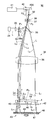
- FIG. 1 is a schematic configuration diagram showing an embodiment of a lens image pickup apparatus according to the present invention.
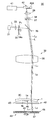
- FIG. 2 is a diagram showing a path of a light beam that passes only through the non-marked portion of the lens to be examined.
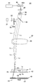
- FIG. 3 is a diagram showing a path of a light beam that passes through the mark.
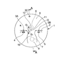
- FIG. 4A is a plan view showing the positional relationship between the marks and the geometric center of the progressive multifocal lens.
- FIG. 4B is a cross-sectional view taken along line AA.
- FIG. 5 is a diagram for explaining mark detection.
- FIG. 6 is a diagram for explaining mark detection.
- FIG. 7 is a diagram for explaining mark detection.
- FIG. 8 is a diagram for explaining mark detection.
- FIG. 9 is a diagram for explaining mark detection.
- FIG. 10 is a view showing an image of a mark obtained by the apparatus of the present invention.
- FIG. 11 is a cross-sectional view of a corner cube prism sheet showing another
- test lens is a divergent progressive multifocal lens and a hidden mark (hereinafter referred to as a mark) formed on the convex surface is detected.
- reference numeral 1 denotes a test lens, which is a circular (for example, 80 mm ⁇ ) plastic progressive multifocal lens whose convex surface 1a is polished.
- Reference numeral 2 denotes a horizontal reference line passing through the geometric center O of the test lens 1, and 3 ⁇ / b> A, 3 ⁇ / b> B, and 3 ⁇ / b> C are marks formed on the convex surface 1 a of the test lens 1.
- These marks 3A, 3B, 3C are formed in the form of minute protrusions (for example, a height of about 2 to 4 ⁇ m).
- the two marks 3A and 3B are formed at two locations on the horizontal reference line 2 that are equidistant (for example, 17 mm) from the geometric center O to the left and right. These marks 3A and 3B are displayed with the same small circle or small circle and letters, and the addition power (external vertex refractive power and near distance of the distance portion) of the lens 1 to be tested is displayed under the marks 3A and 3B.
- a number 4 for displaying the difference in outer apex refractive power of the use part) and an identification mark 5 for displaying the type of lens are also displayed in the form of minute protrusions.
- the number 4 indicating the addition power is displayed as a three-digit number (for example, 300) under the mark 3A located on the ear side when worn.
- FIG. 4 shows a lens for the right eye, and the left mark 3A is indicated by a small circle “ ⁇ ” and the right mark 3B is indicated by a Roman letter “H”.
- the mark 3 ⁇ / b> C is an identification mark for a spectacle store, and is formed of, for example, a round convex mark and is displayed near the outer periphery of the convex surface 1 a.
- a test lens 1 composed of a progressive multifocal lens has a distance power measurement portion 6, a near power measurement portion 7, a distance viewing portion (distance portion) 8, a near viewing portion (near portion) 9 and a power level. It has a continuously changing portion (progressive portion) 10.
- the positions of the distance power measurement portion 6, the near power measurement portion 7 and the eye point 11 of the lens 1 to be examined differ depending on the lens design, but a predetermined reference position away from the geometric center O, for example, the eye point 11 is geometric.
- the distance center 1 is positioned above the academic center O by a predetermined distance d 1 (eg, 2 mm), and the distance center 12 is positioned above the eye point 11 by a predetermined distance d 2 (eg, 4 mm). It has been. Therefore, when the images of the marks 3A and 3B are taken and the position coordinates are calculated by image processing, the positions of the geometric center O and the eye point 11 can be obtained.
- the lens image pickup device 30 includes a light source 31 disposed on the convex surface 1 a side of the test lens 1 and an optical device 32 that guides the light L emitted from the light source 31 to the test lens 1. Yes.
- the light source 31 is used to irradiate the test lens 1 and obtain a clear image of the marks 3A, 3B, 3C, the number 4 indicating the addition power, and the identification mark 5, and a monochromatic point light source is used.
- the monochromatic point light source is used as a broad term including a laser light source that is a point light source and a light source that can be substantially regarded as a point light source, for example, an LED.
- a red semiconductor laser is used as a point light source is shown.
- the optical device 32 includes a condenser lens 33 that condenses the light L emitted from the light source 31, a transmission-type rotational scattering plate 34 disposed in front of the condenser lens 33, and light that has passed through the transmission-type rotational scattering plate 34.
- the transmission type rotary scattering plate 34 is used to remove speckles and fringes, and is a transparent scatterer made of glass or the like.
- the transmission type rotary scattering plate 34 is rotated by a drive motor (not shown) when measuring the mark of the lens 1 to be examined.
- the light L from the light source 31 is configured to be scattered.
- the transmission type rotary scattering plate 34 has a rough surface 34a facing the half mirror 35 and is disposed on the focal position P 1 of the condenser lens 33.
- the half mirror 35 has appropriate transmittance and reflectance, reflects the light L from the light source 31 that has passed through the condenser lens 33 and the transmission-type rotational scattering plate 34 toward the test lens 1, and the test lens 1 side. Light L 2 and L 3 returning from the light is transmitted.
- the collimator lens 36 is disposed in the optical path between the lens 1 to be examined and the half mirror 35, and the light from the light source 31 that has been transmitted through the condenser lens 33 and the transmissive rotation scattering plate 34 and reflected by the half mirror 35. L is converted into parallel light L 1 .
- the test lens 1 is disposed at a focal position P 2 below the collimator lens 36.
- An aperture stop 37, a bandpass filter 38, a re-imaging lens 39, an imaging device 40, and an image processing device 41 are disposed on the opposite side of the half mirror 35 from the lens 1 to be examined.
- the aperture stop 37 is disposed on the focal position P 3 above the collimator lens 36 and limits the diameter of the light beam incident from the collimator lens 36. More specifically, the aperture diameter of the aperture stop 37 is set to be smaller than the beam diameter from the mark C on the convex surface 1a of the lens 1 to be tested and larger than the beam diameter from the non-mark portion.
- the position where the aperture stop 37 is disposed is not limited to the focal position P 3 of the collimator lens 36.
- An equivalent function can be realized by disposing an aperture stop 37 at the exit pupil position of the collimator lens 36.
- the band pass filter 38 transmits only the wavelength band of the light source 31 and cuts extraneous light, and is disposed between the aperture stop 37 and the re-imaging lens 39.
- the re-imaging lens 39 condenses the light L 2 and L 3 that have passed through the bandpass filter 38 on the imaging device 40.
- the imaging device 40 includes a plurality of CCDs 40A that form a light receiving surface, and an image processing device 41 is electrically connected thereto.
- the CCD 40A is disposed at the focal position P 4 of the re-imaging lens 39.
- the focal position P 4 of the re-imaging lens 39 has a conjugate relationship with the convex surface 1a on the collimator lens 36 side of the lens 1 to be examined.
- the lens image pickup device 30 includes a lens holding device 42 and a rotary reflector 43 disposed on the concave surface 1b side of the lens 1 to be examined.
- the lens holding device 42 sucks and fixes the center of the concave surface 1b of the lens 1 to be examined, and includes a transparent plate 45 and a lens suction tube 46 erected at the center of the upper surface of the transparent plate 45.
- the inside of the suction cylinder 46 is evacuated by a vacuum pump so that the center of the concave surface 1b of the lens 1 to be tested is suction fixed to the upper surface of the lens suction cylinder 46.
- the lens adsorption cylinder 46 has a sufficiently small outer diameter (for example, 8 mm ⁇ ) so as not to hinder the projection of the marks 3A, 3B, 3C of the lens 1 to be examined, the number 4 indicating the addition power, and the identification mark 5. ing.
- the rotary reflector 43 retroreflects the light L 1 transmitted through the test lens 1 in the same direction as the incident direction, and includes a rotary plate 47 and a corner cube prism sheet adhered to the surface of the rotary plate 47. 48.
- the corner cube prism sheet 48 is made of plastic having a thickness of about 0.3 mm to 0.5 mm, and a plurality of corner cube prisms (hereinafter also referred to as prisms) 49 are formed on the surface, and the entire surface is transparent. It is protected by a protective film.
- the prism 49 itself is a conventionally known one, and is constituted by three orthogonal total reflection surfaces, thereby reflecting the parallel light L 1 transmitted through the lens 1 in the same direction as the incident direction, that is, retroreflection. It has a function.
- the rotating reflector 43 is configured to be rotated at a high speed (for example, 3400 rpm) by a drive motor (not shown) in order to make the surface brightness and background uniform, similarly to the transmissive rotating scattering plate 34. Yes.
- the light L emitted from the light source 31 exists infinitely, in FIG. 1, only three lights L scattered by the transmission rotation scattering plate 34 are shown, and these lights L are reflected by the half mirror 35, respectively.
- the mark 3C and the two non-mark parts of the lens 1 to be examined are respectively irradiated and retroreflected by the prism 49, and the imaging device
- the four light beams L 2 and L 3 condensed on the 40 CCD 40A are shown, light beams that irradiate and transmit other different parts of the lens 1 to be examined are similarly condensed on the CCD 40A to form an image. Needless to say.
- the lens 1 to be tested is placed on the upper surface opening of the lens suction tube 46 with the convex surface 1a facing up.
- the inside of the lens adsorption cylinder 46 is evacuated by an evacuation apparatus, whereby the lens 1 to be examined is adsorbed and fixed to the upper surface opening of the lens adsorption cylinder 46.
- the light source 31 is turned on to emit light (red laser light) L.
- the light L emitted from the light source 31 is collected by the condenser lens 33, converted to scattered light by passing through the transmission type rotational scattering plate 34, and when reflected on the half mirror 35, it is reflected in the direction of the test lens 1 and is reflected by the collimator lens. is further converted into parallel light L 1 transmits through the 36.
- the parallel light L 1 becomes divergent light by passing through the lens 1 to be measured from the convex surface 1a side to the concave surface 1b side (in the case of a convex lens having convergent refractive power, it becomes convergent light).
- the test lens 1 passes through the concave surface 1b and returns to the convex surface 1a side.
- the reflected light L 2 is diffused when passing through the test lens 1, but the degree of diffusion of the light beam in the non-marked part when passing through the convex surface 1 a made up of the non-marked part is so small that it can be ignored.
- the retroreflected light has a sufficiently small beam diameter. For this reason, the retroreflected light L 2 has almost no loss of light when passing through the aperture stop 37 after re-transmitting the collimator lens 36.
- the retroreflected light L 2 that has passed through the aperture stop 37 passes through the band-pass filter 38 and the re-imaging lens 39 and is condensed on the CCD 40A of the imaging device 40, thereby forming a bright image.
- the parallel light L 1 that has passed through the collimator lens 36 passes through the test lens 1, strikes the prism 49, is retroreflected, and passes through the test lens 1 again.
- the reflected light L 3 diffuses when transmitted through the mark 3C.
- the degree of this diffusion is greater than the retroreflected light L 2 that passes through the non-marked portion.
- the light L 3 transmitted through the mark 3C becomes divergent retroreflected light and returns in the same direction as the incident direction and passes through the collimator lens 36.
- the aperture stop When passing through 37 light is lost.
- the divergent retroreflected light L 3 passes through the band-pass filter 38 and the re-imaging lens 39 and is then condensed on the CCD 40A of the imaging device 40. For this reason, the illuminance of the mark 3C on the CCD 40A is lower than the illuminance of the non-mark part, and the mark 3C can be captured as a clear image.
- the imaging device 40 converts the light received by the CCD 40A into an electrical signal and sends it to the image processing device 41.
- the image processing device 41 processes the image information from the imaging device 40 to identify the delivery eyeglass store by the mark 3C. Further, by receiving the image information of the marks 3A, 3B, etc., the position of the geometric center O of the lens, the position of the eye point 11, etc. are calculated from the position information of these marks 3A, 3B.
- FIG. 5 is a diagram showing the path of the light beam when only the non-mark portion is transmitted and not transmitted through the mark 3C.
- the test lens 1 is a minus lens and the size of the prism 49 is appropriate, the parallel light L 1 incident on the non-marked portion of the convex surface 1 a at the periphery of the test lens 1 is diffused when passing through the test lens 1.
- the light enters the prism 49 it is totally reflected in the same direction as the incident direction.
- the incident point X 1 of the parallel light L 1 light emitted from the reflected convex 1a by the prism 49 (retro-reflected light) and the emission point X 2 of the L 2, slightly offset in the optical axis direction of the lens 1 Yes.
- the incident point X 1 and the exit point X 2 of the convex surface 1a can be regarded as having substantially the same surface curvature, the light L 2 incident on the prism 49 and reflected is parallel to the parallel light L 1. It returns to the original direction as retroreflected light.
- the retroreflected light L 2 passes through the collimator lens 36, the half mirror 35, the aperture stop 37, the band pass filter 38, and the re-imaging lens 39 shown in FIGS. 1 to 3 and then on the CCD 40 A of the imaging device 40.
- a bright image is formed by focusing on the light.
- FIG. 6 is a diagram showing the path of the light beam when passing through the mark 3C and the non-mark part.
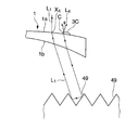
- the parallel light L 1 incident on and transmitted through the peripheral edge C of the mark 3C becomes a diffused light L 3 because the surface curvature of the peripheral edge C is completely different from the surface curvature of the non-marked part.
- the prism 49 When incident on the prism 49, it is totally reflected in the same direction as the incident direction. Then, the light passes through the non-marked portion of the lens 1 to be examined, exits from the exit point X 3 , becomes light parallel to the parallel light L 1, and returns to the original direction.
- the light beam has a larger divergence than the retroreflected light L 2 incident on the non-mark portion and emitted from the non-mark portion. Retroreflected light. Therefore, when the divergent retroreflected light L 3 passes through the aperture stop 37 as described above, the loss of light is large, and the illuminance on the CCD 40A is lower than that of the non-marked portion.
- FIG. 7 is a diagram showing the path of light when passing through the non-mark part and passing through the peripheral part of the mark 3C.
- the parallel light L 1 that is incident and transmitted from the point X 4 that is a non-mark portion of the convex surface 1 a but close to the mark 3 C is incident on the prism 49, and is totally reflected in the same direction as the incident direction, and the peripheral portion C of the mark 3 C.
- the light L 1 since the light L 1 has a surface curvature that is completely different from the surface curvature of the non-marked portion, the light L 1 becomes a divergent retroreflected light L 4 that diffuses and has a large light beam diameter. The light is emitted to the convex surface 1a side of the lens 1 to be examined. Then, the divergent retroreflected light L 4 has a large light loss when passing through the aperture stop 37 like the divergent retroreflected light L 3, and the illuminance on the CCD 40A is lower than that of the non-marked portion.
- FIG. 8 is a diagram showing a path of a light beam when entering the center portion of the mark 3C and exiting from a point close to the mark 3C of the non-mark portion.
- the parallel light L 1 incident on the central portion X 5 of the mark 3C and transmitted through the test lens 1 enters the prism 49 and is totally reflected in the same direction as the incident direction, and then passes through the non-mark portion of the test lens 1. transmitted, emitted from the emission point X 6. Since the central portion of the mark 3C has a surface curvature close to the surface curvature of the non-mark portion, the diffusion of the parallel light L 1 by the mark 3 is very slight.
- the light is emitted as retroreflected light L 5 having a small beam diameter from the exit point X 6 to the convex surface 1 a side of the test lens 1.
- the retroreflected light L 5 is not lost by the aperture stop 37, passes through the band-pass filter 38 and the re-imaging lens 39, and is condensed on the CCD 40 A of the image pickup device 40, whereby FIG. As with the retroreflected light L 2 shown in FIG. 5, a bright image is formed.
- FIG. 9 is a diagram showing the path of the light beam when it is incident and transmitted from a point near the mark 3C of the non-mark part and is emitted from the center part of the mark 3C at the time of re-transmission.
- the parallel light L 1 that has entered from the point X 7 near the mark 3C at the non-mark portion of the test lens 1 and transmitted through the test lens 1 enters the prism 49 and is totally reflected in the same direction as the incident direction. Then, the reflected light L 6 is emitted from the central portion X 5 marks 3C.
- the central portion X 5 of the mark 3C has a surface curvature close to the surface curvature of the non-marked portion of the convex surface 1a as described above, even if the reflected light L 6 passes through the central portion X 5 of the mark 3C.
- the light is emitted from the exit point X 5 to the convex surface 1 a side of the test lens 1 as retroreflected light having a small beam diameter. Therefore, the retroreflected light L 6, there is no loss of light due to the aperture stop 37 and is focused on CCD40A transmitted through the band-pass filter 38 and re-imaging lens 39, retroreflected light L 2, L A bright image is formed as in 5 .
- the lens image pickup device 30 uses the corner cube prism 49 to diffuse the light L 2 , L 5 , and L 6 that pass through only the non-marked portion of the convex surface 1a in the round trip.
- divergent retroreflected light having a large degree of diffusion, the light is returned to the convex surface 1a side of the lens 1 to be examined and condensed on the light receiving surface of the CCD 40A.
- the retroreflected light L 2 , L 5 , L 6 and divergent retroreflected light L 3 , L 4 When such retroreflected light L 2 , L 5 , L 6 and divergent retroreflected light L 3 , L 4 are guided to the aperture stop 37, the retroreflected light L 2 , L 5 , L 6 has a sufficiently small beam diameter. Therefore, no light is lost when passing through the aperture stop 37, and the illuminance on the light receiving surface of the CCD 40A can be increased.
- the divergent retroreflected lights L 3 and L 4 the light beam diameter is larger than the aperture diameter of the aperture stop 37, so that the light loss due to the aperture stop 37 is large, and the illuminance of the mark on the light receiving surface of the CCD 40 A decreases.
- the lens image pickup device 30 According to the lens image pickup device 30 according to the present invention, it is possible to obtain a clear mark image having a high contrast as compared with the case where the above-described conventional reflective screen is used. Therefore, image processing is easy, and the design of the image processing circuit can be facilitated.
- FIG. 10 is a view showing an image of the mark 3C obtained by the apparatus of the present invention.
- the image of the mark 3C formed on the CCD 40A of the imaging device 40 becomes a clear image with a dark peripheral edge and a bright central portion, and image processing by the image processing device 41 is easy. To.
- the present invention includes the transmission type rotary scattering plate 34, it is possible to suppress and prevent the generation of speckles and the like by the laser light source. Further, since the brightness of the surface of the corner cube prism sheet 48 serving as the background of the image is averaged by the rotating reflector 43, the image processing can be further facilitated.
- test lens 1 is a colored lens
- an image with clear contrast can be obtained if the mark shape is a shape that can obtain retroreflected light and divergent retroreflected light.
- the CCD40A of the imaging device 40 is set sufficiently smaller than the subject lens 1, a focal length of the focal length (f 1) and the re-imaging lens 39 of the collimator lens 36 (f 2 ) Ratio (horizontal magnification) is sufficiently large, and as a result, the vertical magnification can be sufficiently large, so that the depth of focus can be increased. As an effect of this, it is possible to minimize the blurring when observing the thick lens, and to reduce the shadow of the end surface portion of the minus lens.
- the sample lens from the collimator lens 36 1 is incident obliquely with respect to the end surface portion of the light source 1 and is reflected by the edge surface and reflected by the corner cube prism 49, it does not become effective retroreflected light, and is not condensed on the CCD 40A of the imaging device 40 and is clear.
- the corner cube prism 49 is refracted toward the center of the lens and does not hit the edge surface and passes through the lens. When reflected at, the light becomes retroreflected light, returns to the original direction, and is condensed on the CCD 40A, so that a clear image is obtained. If the conjugate optical system composed of the collimator lens 36 and the re-imaging lens 39 is configured as a double-sided telecentric optical system, even if the thickness fluctuation of the test lens 1 occurs and the blur occurs, the blur occurs. It is possible to obtain the same position of the center of gravity as the image in the case of not doing so.
- the image detection of the mark 3C formed in a convex shape has been described.
- the concave mark has a symmetrical shape with the convex mark, and the peripheral edge of the concave has a completely different surface curvature from the convex surface 1a of the lens 1 to be examined. Since the degree is large, it becomes divergent retroreflected light, and the light transmitted through the central part of the recess becomes retroreflected light because the degree of diffusion is small. For this reason, it is possible to obtain a mark image having a high contrast between the retroreflected light and the divergent retroreflected light and a clear contour shape.
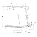
- FIG. 11 is a cross-sectional view of a corner cube prism sheet showing another embodiment of the present invention.
- the corner cube prism sheet 48 is curved in a concave shape on the light source side instead of being formed into a flat plate shape as in the above-described embodiment.
- Other configurations are the same as those of the embodiment shown in FIG.
- the corner cube prism sheet 48 When the corner cube prism sheet 48 is formed in a flat plate shape as indicated by a two-dot chain line, the incident angle ⁇ with respect to the surface of the corner cube prism 49 increases as the light L 1 is farther from the center of the lens 1 to be examined. For this reason, the reflection efficiency of the corner cube prism 49 is lowered. That is, the loss of light increases and the entire image becomes dark. Therefore, when a mark is displayed near the outer periphery of the lens 1 to be examined, it is difficult to obtain a clear image.
- the corner cube prism sheet 48 is curved in a concave shape when viewed from the light source side, the incident angle ⁇ incident on the surface of the corner cube prism 49 even if the light L 1 is far from the center of the lens 1 to be examined. It can be made smaller than in the case of a flat plate. Therefore, the reflection efficiency of the corner cube prism 49 is increased, and the loss of light can be reduced. Thereby, even if the mark is displayed near the outer periphery of the lens 1 to be examined, a clear image can be obtained.
- the light source is a monochromatic point light source.
- the corner cube prism sheet is curved in a concave shape when viewed from the light source side to reduce light loss.
- the corner cube prism sheet is flat, the light transmitted through the test lens is incident on the corner cube prism more obliquely as the light is farther from the center of the test lens. Loss occurs and the reflection efficiency (ratio of incident beam intensity to outgoing beam intensity) decreases. This phenomenon is unfavorable because it causes a decrease in image luminance especially at the outer peripheral portion of the lens to be divergent and lowers the detection sensitivity of marks arranged in the vicinity of the outer peripheral portion.
- the corner cube prism sheet is curved in a concave shape when viewed from the light source side, the light flux that passes through a position far from the center of the test lens having divergence Even so, the angle of incidence on the corner cube prism can be made smaller than in the case of a flat sheet. By doing so, the optical loss can be suppressed to be negligible, and therefore, even when the mark is displayed near the outer periphery of the lens to be examined, the mark can be captured as a clear image.
- the brightness decrease at the outer peripheral portion does not appear as markedly as in a divergent test lens, and the optical path from the test lens to the corner cube prism sheet is convergent. Therefore, even if the corner cube prism sheet is curved concavely, the effective range of light on the prism sheet is limited to the vicinity of the center of the prism sheet, and the inclination angle of the prism sheet in that region is small. Even when the prism sheet is configured as a flat surface, the reduction in reflection efficiency is kept small enough to be ignored.
- the corner cube prism sheet When the corner cube prism sheet is curved in a convex shape when viewed from the light source side, the incident angle of the light that has passed through the outer periphery of the test lens exhibiting a divergent refractive power is incident on the corner cube prism increases. Loss is large, the reflection efficiency is low, and the mark cannot be captured as a clear image.
- the optical device includes a condenser lens that collects the light emitted from the light source, a transmission-type rotational scattering plate that scatters the light transmitted through the condenser lens, and the transmission-type rotational scattering plate.
- a half mirror is provided that guides the transmitted light to the collimator lens, passes through the lens to be examined, reflects against the rotating reflector, retransmits the lens to be examined and the collimator lens, and guides the returning light to the aperture stop.
- the imaging apparatus is provided with a band-pass filter that transmits only the wavelength band of the light source light. Since the band pass filter transmits only the wavelength range of the light source light, it is less affected by disturbance light, and can capture an image with high contrast.
- a preferred embodiment of the present invention includes an image processing device that processes an image picked up by the image pickup device.
Landscapes
- Physics & Mathematics (AREA)
- General Physics & Mathematics (AREA)
- Chemical & Material Sciences (AREA)
- Analytical Chemistry (AREA)
- Life Sciences & Earth Sciences (AREA)
- Health & Medical Sciences (AREA)
- Geometry (AREA)
- Biochemistry (AREA)
- General Health & Medical Sciences (AREA)
- Immunology (AREA)
- Pathology (AREA)
- Testing Of Optical Devices Or Fibers (AREA)
- Investigating Materials By The Use Of Optical Means Adapted For Particular Applications (AREA)
Priority Applications (2)
| Application Number | Priority Date | Filing Date | Title |
|---|---|---|---|
| US12/810,144 US20100283999A1 (en) | 2007-12-26 | 2008-12-24 | Lens image sensing apparatus |
| EP08865745.7A EP2239552B1 (de) | 2007-12-26 | 2008-12-24 | Bildaufnahmevorrichtung für eine linse |
Applications Claiming Priority (2)
| Application Number | Priority Date | Filing Date | Title |
|---|---|---|---|
| JP2007-334895 | 2007-12-26 | ||
| JP2007334895A JP4906708B2 (ja) | 2007-12-26 | 2007-12-26 | レンズ用画像撮像装置 |
Publications (1)
| Publication Number | Publication Date |
|---|---|
| WO2009081928A1 true WO2009081928A1 (ja) | 2009-07-02 |
Family
ID=40801228
Family Applications (1)
| Application Number | Title | Priority Date | Filing Date |
|---|---|---|---|
| PCT/JP2008/073398 Ceased WO2009081928A1 (ja) | 2007-12-26 | 2008-12-24 | レンズ用画像撮像装置 |
Country Status (4)
| Country | Link |
|---|---|
| US (1) | US20100283999A1 (de) |
| EP (1) | EP2239552B1 (de) |
| JP (1) | JP4906708B2 (de) |
| WO (1) | WO2009081928A1 (de) |
Cited By (3)
| Publication number | Priority date | Publication date | Assignee | Title |
|---|---|---|---|---|
| JP2013104780A (ja) * | 2011-11-14 | 2013-05-30 | Shimadzu Corp | 試料支持治具 |
| CN110146257A (zh) * | 2019-05-17 | 2019-08-20 | 中国科学院上海技术物理研究所 | 一种快速测量空间激光载荷光轴变化的装置及方法 |
| CN116086776A (zh) * | 2023-01-19 | 2023-05-09 | 南京理工大学 | 一种准直光束发散角检测装置及发散角检测方法 |
Families Citing this family (15)
| Publication number | Priority date | Publication date | Assignee | Title |
|---|---|---|---|---|
| US10259607B2 (en) * | 2008-03-04 | 2019-04-16 | Vanrx Pharmasystems Inc. | Aseptic robotic filling system and method |
| EP2625508A2 (de) * | 2010-10-08 | 2013-08-14 | Dark Field Technologies, Inc. | Rückstrahlende bildgebung |
| US10976572B2 (en) | 2011-12-22 | 2021-04-13 | Carl Zeiss Vision International Gmbh | Method for storing information on a spectacles lens, spectacles lens blank or spectacles lens semi-finished product |
| DE102011089704B4 (de) * | 2011-12-22 | 2020-06-18 | Carl Zeiss Vision International Gmbh | Verfahren zum Speichern von Information auf einem Brillenglas, als Brillenglas-Rohling oder Brillenglas-Halbfabrikat ausgebildeter Glas- oder Kunststoffkörper, Vorrichtung für das Speichern von Information, Verfahren zum Auslesen sowie Lesegerät |
| FR3017964B1 (fr) * | 2014-02-27 | 2016-03-25 | Essilor Int | Instrument optique pour reperer au moins un point caracteristique d'une lentille ophtalmique |
| FR3017963B1 (fr) * | 2014-02-27 | 2016-03-25 | Essilor Int | Instrument optique pour identifier et localiser des microgravures presentes sur une lentille ophtalmique |
| CN104931238B (zh) | 2015-05-18 | 2018-03-30 | 京东方科技集团股份有限公司 | 一种测试透明显示基板透明效果的设备及方法 |
| DE102015115735B3 (de) * | 2015-09-17 | 2017-03-23 | Carl Zeiss Vision International Gmbh | Vorrichtung und Verfahren zum Sichtbarmachen eines Signierzeichens auf einem Brillenglas |
| EP3943909A1 (de) * | 2017-04-13 | 2022-01-26 | Carl Zeiss Vision International GmbH | Verfahren zur bereitstellung eines brillenglas-rohlings bzw. eines brillenglas-halbfabrikats für die herstellung eines brillenglases |
| CN113484322B (zh) * | 2021-07-13 | 2023-01-10 | 天津大学 | 可实时反馈轴向光阱位置的光镊超分辨成像方法和系统 |
| CN114139562B (zh) * | 2021-12-08 | 2025-07-01 | 深圳思谋信息科技有限公司 | 二维码检测装置 |
| KR20240127754A (ko) * | 2023-02-16 | 2024-08-23 | 삼성전자주식회사 | 광학 계측 설비 |
| CN118624183B (zh) * | 2024-08-09 | 2024-11-12 | 厦门捷能通光电科技有限公司 | 一种灯珠用透镜光损检测装置及方法 |
| EP4726373A1 (de) * | 2024-10-10 | 2026-04-15 | Carl Zeiss Jena GmbH | Inspektionsverfahren, herstellungsverfahren und inspektionssystem |
| KR102928061B1 (ko) | 2025-07-16 | 2026-02-19 | (주) 캔랩 | 렌즈 결함 검사 시스템 및 방법 |
Citations (10)
| Publication number | Priority date | Publication date | Assignee | Title |
|---|---|---|---|---|
| JPH085571A (ja) * | 1994-06-21 | 1996-01-12 | New Kurieishiyon:Kk | 検査装置 |
| JPH11118668A (ja) * | 1997-10-16 | 1999-04-30 | Sumitomo Chem Co Ltd | 物体の欠陥の検査方法および検査装置 |
| JP2001524663A (ja) * | 1997-11-20 | 2001-12-04 | トロペル コーポレーション | 透明な面平行プレートを測定するためのすれすれ入射の干渉測定 |
| JP2002162655A (ja) * | 2000-11-27 | 2002-06-07 | Sony Corp | 光学装置 |
| WO2005096074A1 (ja) * | 2004-03-31 | 2005-10-13 | Kabushiki Kaisha Topcon | 治具装着装置 |
| WO2005098521A1 (ja) * | 2004-03-31 | 2005-10-20 | Topcon Corporation | 眼鏡レンズの吸着治具取付装置、及び吸着治具取付位置決定方法 |
| JP2006118935A (ja) * | 2004-10-20 | 2006-05-11 | Hoya Corp | レンズ用撮像装置 |
| JP2006142356A (ja) * | 2004-11-22 | 2006-06-08 | Hoya Corp | マーキング装置及びマーキング方法 |
| JP2006247825A (ja) * | 2005-02-08 | 2006-09-21 | Topcon Corp | 眼鏡レンズの吸着治具取付装置 |
| JP2007526996A (ja) * | 2003-07-17 | 2007-09-20 | カール ツァイス ビジョン ゲーエムベーハー | 眼鏡レンズ上のマークを可視化する方法および装置 |
Family Cites Families (9)
| Publication number | Priority date | Publication date | Assignee | Title |
|---|---|---|---|---|
| US3375754A (en) * | 1964-09-29 | 1968-04-02 | Bausch & Lomb | Lens testing autocollimator |
| JPS604401B2 (ja) * | 1975-01-21 | 1985-02-04 | コニカ株式会社 | 干渉装置 |
| DE29901791U1 (de) * | 1999-02-02 | 2000-07-06 | Novartis Ag, Basel | Linsenmesseinrichtung |
| DE19942998B4 (de) * | 1999-09-09 | 2012-02-09 | Carl Zeiss Jena Gmbh | Mikroskop zur Auf- und Durchlichtmikroskopie |
| CA2413343A1 (en) * | 2002-12-02 | 2004-06-02 | Peter Vokhmin | Method and apparatus for testing optical components |
| FR2853734B1 (fr) * | 2003-04-14 | 2005-05-27 | Tecoptique | Systeme de visualisation de marquages optiques d'un verre ophtalmique, dispositif de tamponnage et procede d'orientation de verres utilisant un tel systeme |
| JP4822318B2 (ja) * | 2005-10-18 | 2011-11-24 | 株式会社トプコン | レンズ吸着治具装着装置に用いられるレンズの位置特定方法およびレンズ吸着治具装着装置 |
| JP2007252402A (ja) * | 2006-03-20 | 2007-10-04 | Topcon Corp | 眼科測定装置 |
| JP4970149B2 (ja) * | 2007-05-31 | 2012-07-04 | 株式会社ニデック | カップ取付け装置 |
-
2007
- 2007-12-26 JP JP2007334895A patent/JP4906708B2/ja not_active Expired - Fee Related
-
2008
- 2008-12-24 US US12/810,144 patent/US20100283999A1/en not_active Abandoned
- 2008-12-24 WO PCT/JP2008/073398 patent/WO2009081928A1/ja not_active Ceased
- 2008-12-24 EP EP08865745.7A patent/EP2239552B1/de not_active Not-in-force
Patent Citations (10)
| Publication number | Priority date | Publication date | Assignee | Title |
|---|---|---|---|---|
| JPH085571A (ja) * | 1994-06-21 | 1996-01-12 | New Kurieishiyon:Kk | 検査装置 |
| JPH11118668A (ja) * | 1997-10-16 | 1999-04-30 | Sumitomo Chem Co Ltd | 物体の欠陥の検査方法および検査装置 |
| JP2001524663A (ja) * | 1997-11-20 | 2001-12-04 | トロペル コーポレーション | 透明な面平行プレートを測定するためのすれすれ入射の干渉測定 |
| JP2002162655A (ja) * | 2000-11-27 | 2002-06-07 | Sony Corp | 光学装置 |
| JP2007526996A (ja) * | 2003-07-17 | 2007-09-20 | カール ツァイス ビジョン ゲーエムベーハー | 眼鏡レンズ上のマークを可視化する方法および装置 |
| WO2005096074A1 (ja) * | 2004-03-31 | 2005-10-13 | Kabushiki Kaisha Topcon | 治具装着装置 |
| WO2005098521A1 (ja) * | 2004-03-31 | 2005-10-20 | Topcon Corporation | 眼鏡レンズの吸着治具取付装置、及び吸着治具取付位置決定方法 |
| JP2006118935A (ja) * | 2004-10-20 | 2006-05-11 | Hoya Corp | レンズ用撮像装置 |
| JP2006142356A (ja) * | 2004-11-22 | 2006-06-08 | Hoya Corp | マーキング装置及びマーキング方法 |
| JP2006247825A (ja) * | 2005-02-08 | 2006-09-21 | Topcon Corp | 眼鏡レンズの吸着治具取付装置 |
Cited By (4)
| Publication number | Priority date | Publication date | Assignee | Title |
|---|---|---|---|---|
| JP2013104780A (ja) * | 2011-11-14 | 2013-05-30 | Shimadzu Corp | 試料支持治具 |
| CN110146257A (zh) * | 2019-05-17 | 2019-08-20 | 中国科学院上海技术物理研究所 | 一种快速测量空间激光载荷光轴变化的装置及方法 |
| CN110146257B (zh) * | 2019-05-17 | 2024-02-20 | 中国科学院上海技术物理研究所 | 一种快速测量空间激光载荷光轴变化的装置及方法 |
| CN116086776A (zh) * | 2023-01-19 | 2023-05-09 | 南京理工大学 | 一种准直光束发散角检测装置及发散角检测方法 |
Also Published As
| Publication number | Publication date |
|---|---|
| JP4906708B2 (ja) | 2012-03-28 |
| EP2239552A4 (de) | 2015-07-08 |
| JP2009156702A (ja) | 2009-07-16 |
| EP2239552A1 (de) | 2010-10-13 |
| US20100283999A1 (en) | 2010-11-11 |
| EP2239552B1 (de) | 2018-09-19 |
Similar Documents
| Publication | Publication Date | Title |
|---|---|---|
| JP4906708B2 (ja) | レンズ用画像撮像装置 | |
| TWI427286B (zh) | 用於檢測玻璃板之裝置及方法 | |
| JP5388543B2 (ja) | 外観検査装置 | |
| US20040004727A1 (en) | Three-dimensional shape measuring method, and three-dimensional shape measuring apparatus | |
| JP5636413B2 (ja) | 眼鏡レンズ上のシグネチャマークを可視化する方法及び装置 | |
| US20110317156A1 (en) | Inspection device for defect inspection | |
| CN103119420B (zh) | 折射率测定装置和折射率测定方法 | |
| JPS58219441A (ja) | 凸面体の表面欠陥検査装置 | |
| EP1035408A1 (de) | Vorrichtung zur messung der eigenschaften eines optischen winkels | |
| JP3617805B2 (ja) | 眼鏡レンズ用画像撮像処理装置 | |
| US6184977B1 (en) | Inspection method and inspection device | |
| JP2007171149A (ja) | 表面欠陥検査装置 | |
| JP6385974B2 (ja) | 全反射吸収スペクトル測定用光学器具、および、測定装置 | |
| TW200525142A (en) | Method and device for detecting defects of glass plate | |
| US7796276B2 (en) | Apparatus and method for examining a curved surface | |
| TWI250517B (en) | Appearance inspector | |
| JP3417736B2 (ja) | 光学部材検査装置 | |
| KR101447857B1 (ko) | 렌즈 모듈 이물 검사 시스템 | |
| JP3388285B2 (ja) | 検査装置 | |
| CN220039391U (zh) | 组装平行度检测装置及其系统 | |
| JP2005316436A (ja) | 眼鏡レンズへの自動装着装置 | |
| JP2821460B2 (ja) | 透明基板の傷検査装置 | |
| JP4563736B2 (ja) | 吸着治具の装着装置 | |
| JP3417737B2 (ja) | 光学部材検査装置 | |
| JP2000295639A (ja) | 固体撮像素子検査用照明装置及びそれに用いる調整工具 |
Legal Events
| Date | Code | Title | Description |
|---|---|---|---|
| 121 | Ep: the epo has been informed by wipo that ep was designated in this application |
Ref document number: 08865745 Country of ref document: EP Kind code of ref document: A1 |
|
| WWE | Wipo information: entry into national phase |
Ref document number: 2008865745 Country of ref document: EP |
|
| WWE | Wipo information: entry into national phase |
Ref document number: 12810144 Country of ref document: US |
|
| NENP | Non-entry into the national phase |
Ref country code: DE |