WO2009084453A1 - Elément de chauffage de gaine et bougie de préchauffage - Google Patents
Elément de chauffage de gaine et bougie de préchauffage Download PDFInfo
- Publication number
- WO2009084453A1 WO2009084453A1 PCT/JP2008/073086 JP2008073086W WO2009084453A1 WO 2009084453 A1 WO2009084453 A1 WO 2009084453A1 JP 2008073086 W JP2008073086 W JP 2008073086W WO 2009084453 A1 WO2009084453 A1 WO 2009084453A1
- Authority
- WO
- WIPO (PCT)
- Prior art keywords
- sheath
- coil
- heating coil
- heat generating
- sample
- Prior art date
- Legal status (The legal status is an assumption and is not a legal conclusion. Google has not performed a legal analysis and makes no representation as to the accuracy of the status listed.)
- Ceased
Links
Images








Classifications
-
- H—ELECTRICITY
- H05—ELECTRIC TECHNIQUES NOT OTHERWISE PROVIDED FOR
- H05B—ELECTRIC HEATING; ELECTRIC LIGHT SOURCES NOT OTHERWISE PROVIDED FOR; CIRCUIT ARRANGEMENTS FOR ELECTRIC LIGHT SOURCES, IN GENERAL
- H05B3/00—Ohmic-resistance heating
- H05B3/40—Heating elements having the shape of rods or tubes
- H05B3/42—Heating elements having the shape of rods or tubes non-flexible
- H05B3/44—Heating elements having the shape of rods or tubes non-flexible heating conductor arranged within rods or tubes of insulating material
-
- F—MECHANICAL ENGINEERING; LIGHTING; HEATING; WEAPONS; BLASTING
- F23—COMBUSTION APPARATUS; COMBUSTION PROCESSES
- F23Q—IGNITION; EXTINGUISHING-DEVICES
- F23Q7/00—Incandescent ignition; Igniters using electrically-produced heat, e.g. lighters for cigarettes; Electrically-heated glowing plugs
- F23Q7/001—Glowing plugs for internal-combustion engines
-
- H—ELECTRICITY
- H05—ELECTRIC TECHNIQUES NOT OTHERWISE PROVIDED FOR
- H05B—ELECTRIC HEATING; ELECTRIC LIGHT SOURCES NOT OTHERWISE PROVIDED FOR; CIRCUIT ARRANGEMENTS FOR ELECTRIC LIGHT SOURCES, IN GENERAL
- H05B3/00—Ohmic-resistance heating
- H05B3/10—Heating elements characterised by the composition or nature of the materials or by the arrangement of the conductor
- H05B3/12—Heating elements characterised by the composition or nature of the materials or by the arrangement of the conductor characterised by the composition or nature of the conductive material
- H05B3/14—Heating elements characterised by the composition or nature of the materials or by the arrangement of the conductor characterised by the composition or nature of the conductive material the material being non-metallic
- H05B3/141—Conductive ceramics, e.g. metal oxides, metal carbides, barium titanate, ferrites, zirconia, vitrous compounds
-
- H—ELECTRICITY
- H05—ELECTRIC TECHNIQUES NOT OTHERWISE PROVIDED FOR
- H05B—ELECTRIC HEATING; ELECTRIC LIGHT SOURCES NOT OTHERWISE PROVIDED FOR; CIRCUIT ARRANGEMENTS FOR ELECTRIC LIGHT SOURCES, IN GENERAL
- H05B2203/00—Aspects relating to Ohmic resistive heating covered by group H05B3/00
- H05B2203/027—Heaters specially adapted for glow plug igniters
Definitions
- the present invention relates to a heating sheath heater and a glow plug that uses the sheath heater and is also used to assist in starting a diesel engine.
- glow plugs are used to assist engine startup, stabilize combustion after startup, and purify exhaust gas.
- the glow plug is a so-called metal glow plug in which a heat generating resistor (simply referred to as a heat generating coil) or a control resistor (simply referred to as a control coil) is housed in a metal sheath to form a heater.
- Some heaters are called ceramic glow plugs composed mainly of a ceramic material.
- the operating temperature of the glow plug is high.
- the demand for ceramic glow plugs is increasing because ceramic glow plugs are superior to metal glow plugs in high-temperature durability.
- the current situation is that metal glow plugs are still in demand because they are easy to manufacture and easy to control in terms of construction.
- the metal glow plug exposes the sheath as a heater in the combustion chamber of the engine when in use. Since the combustion chamber has an extremely high temperature and an atmosphere in which unburned gas / combustion gas mixed with fuel drifts, heat resistance such as high temperature corrosion resistance and high temperature strength of the sheath is required. In order to respond to this, a material having excellent heat resistance and corrosion resistance, mainly composed of Ni (nickel) or Fe (iron), such as SUS 310 or Inconel 601 (trade name) is used for the sheath.
- the heat generating coil that functions as a heater more than the sheath exposed to the combustion chamber is regarded as important, and material development is being carried out.
- Fe (iron) -Cr (chromium) -Al (aluminum) -based material is used as the heat generating coil material of the metal glow plug.
- Patent Document 1 the composition of Fe-7.5Al-28Cr is used. A coil material is disclosed. This coil material is used for many glow plugs because of its excellent oxidation resistance.
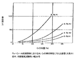
- Non-Patent Document 1 reports “Effects on Life Properties of Al and Cr in Fe—Cr—Al Heating Element (Resistor Alloy Material)” as shown in FIG. According to this, there may be a synergistic effect with Al, the degree of increase in the life value accompanying the increase in Cr content from the time when the Cr content exceeds 20% by weight, Cr is more than 20% by weight It seems desirable to include.
- the above coil material has excellent oxidation resistance, at extremely high temperatures such as 1100 ° C. or higher required by recent engines, it cannot endure actual use, and the heating coil may break. It is considered that the cause of this disconnection is that granular AlN (aluminum nitride) is generated inside the heating coil material with use. Considering a certain cross section of the heat generating coil, if the ratio of the metal portion (the ratio of the high conductivity portion) in the cross sectional area decreases due to the generation of AlN, the resistance value increases thereby, This is because a part that is abnormally heated is formed, and it is considered that the wire is disconnected there.
- Patent Document 2 discloses that the rear end portion of a sheath of a metal glow plug is sealed with an elastic body having a small N 2 (nitrogen) permeability.
- N 2 nitrogen
- this configuration can effectively prevent the entry of nitrogen from the outside of the sheath and suppress the generation of AlN, it still may not be sufficient as the durability of the heating coil. This is because, in the process of filling the sheath with insulating powder during the manufacturing process, oxygen and nitrogen contained in the atmosphere can be mixed in the sheath, so that a component that can affect the coil material is enclosed in the sheath. It is also thought to be because. It is difficult to solve this problem by using a conventional heating resistor material.
- Patent Document 3 In order to improve durability without using a heat generating resistor as a separate material, see Patent Document 3 in which TiO (titanium oxide) is mixed with MgO (magnesium oxide) powder, which is an insulating powder, to serve as an oxygen donor. It is disclosed that the surface layer of the heating resistor is positively oxidized by the above-described method, and that the oxide film prevents the penetration of nitrogen into the heating resistor. At first glance, this configuration seems to have solved the problem of durability of the heating resistor. However, mixing oxygen donors can cause the following problems. The metal (Ti), which plays a role as an oxygen donor and from which oxygen is dissociated, is feared to deteriorate the insulating function as an insulating powder.
- Ti titanium oxide
- the surface temperature of the sheath may not be as expected, and the original performance as a glow plug may not be exhibited.
- the basic configuration as a glow plug is equivalent to the conventional one, and it is preferable to use a technique that improves only the durability of the heating resistor.
- the conventionally known metal glow plug has been sufficiently studied for improving the durability of the heating resistor.
- the heating resistor materials disclosed in Patent Documents 1-3 and Non-Patent Document 1 described above are used as they are, the heat generation performance and durability as a glow plug are not necessarily sufficient.
- the present invention eliminates the problems of heat generation performance, rapid temperature rise performance and reliability, and improves the durability of the heating resistor, while maintaining the same basic structure as the conventional one, so that it has high durability as a sheath heater or glow plug.
- the purpose is to realize sex.
- a cylindrical metal sheath that extends in the axial direction and has a closed end mainly composed of nickel or iron, and is disposed in the sheath along the axial direction, and the distal end is electrically connected to the sheath.
- the connected heat generating coil, the lead member electrically connected to the heat generating coil and positioned in the sheath, the rear end projecting toward the rear end of the sheath, and the heat generating coil in the sheath are filled around An insulating powder and a sealing member that seals the rear end of the sheath, and the inner atmosphere of the sheath sealed by the sealing member is an internal atmosphere in which the partial pressure ratio is greater than the partial pressure of nitrogen than the partial pressure of oxygen
- the heating coil contains iron as a main component, chromium is contained in an amount of 5% by weight to 20% by weight, and aluminum is contained in an amount of more than 8% by weight and 15% by weight or less.
- a glow plug provided with the sheath heater having the above-described configuration is provided.
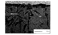
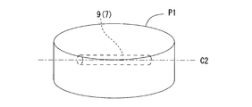
- 7 is a graph showing “effects on the life characteristics of Al and Cr in an Fe—Cr—Al-based heating element (in air)” extracted from Non-Patent Document 1. It is a cross-sectional observation figure of the sample (comparative example) after an evaluation test. It is a cross-sectional observation figure of the sample (Example) after an evaluation test. It is a schematic diagram which shows the state which embedded the measuring object in the resin block in order to observe the cross section of each sample in an evaluation test.
- the glow plug 1 includes a cylindrical housing 2 and a sheath heater 3 attached to the housing 2.
- the housing 2 has a shaft hole 4 penetrating in the direction of the axis C1, and the outer peripheral surface thereof has a hexagonal cross section for engaging a screw portion 5 for attachment to a diesel engine and a tool such as a torque wrench.
- a tool engaging portion 6 is formed.
- a sheath 7 As a lead member for transmitting electric power, a heating coil 9 (heating resistor), and a control coil (control resistor) 10 are integrated in the direction of the axis C1. It is configured.
- the sheath 7 is a cylindrical sheath made of metal having Ni or Fe as a main component (for example, made of SUS 310, Inconel 600, 601 or the like) whose tip is closed. Is fixed to the housing 2 in a protruding state. Inside the sheath 7, a heat generating coil 9 melt-bonded to the distal end of the sheath 7 and a control coil 10 connected in series to the rear end of the heat generating coil 9 are enclosed together with an insulating powder 11 such as MgO.
- the rear end of the sheath 7 is sealed with an annular rubber 17 made of fluororubber between the inner shaft 8 and the rear end.
- the heat generating coil 9 is electrically connected to the sheath 7 at the tip, but the outer peripheral surfaces of the heat generating coil 9 and the control coil 10 and the inner peripheral surface of the sheath 7 are insulated by the intervening insulating powder 11. It is in the state.
- the heating coil 9 is made of an Fe—Cr—Al alloy containing Fe as a main component and containing Cr and Al, and details will be described later. Further, the control coil 10 is made of a material having a temperature coefficient of electrical resistivity larger than that of the material of the heating coil 9, for example, a resistance heating wire mainly composed of Co or Ni typified by a Co (cobalt) -Ni-Fe alloy. It is configured. Thereby, the control coil 10 increases the electric resistance value by receiving its own heat generation and heat generation from the heat generation coil 9, and controls the power supply amount to the heat generation coil 9. Therefore, relatively large electric power is supplied to the heating coil 9 in the initial stage of energization, and the temperature of the heating coil 9 rises rapidly.
- the control coil 10 is heated by the heat generation, the electric resistance value increases, and the power supply to the heat generating coil 9 decreases.
- the temperature rise characteristic of the sheath heater 3 becomes a form in which the temperature is saturated after the temperature is rapidly raised in the initial stage of energization, and thereafter the power supply is suppressed by the action of the control coil 10. That is, the presence of the control coil 10 makes it possible to prevent the temperature of the heat generating coil 9 from excessively rising (overshoot) while improving the rapid temperature rise.
- the sheath 7 is formed with a small-diameter portion 7a that accommodates the heating coil 9 and the like on the distal end side thereof by swaging or the like, and a large-diameter portion 7b that is larger in diameter than the small-diameter portion 7a on the rear end side.
- the large diameter portion 7 b is press-fitted and joined to the small diameter portion 4 a formed in the shaft hole 4 of the housing 2, so that the sheath 7 is held in a state of protruding from the tip of the housing 2.
- the center shaft 8 has its tip inserted into the sheath 7 and is electrically connected to the rear end of the control coil 10 and is inserted through the shaft hole 4 of the housing 2.
- the rear end of the middle shaft 8 protrudes from the rear end of the housing 2, and the rear end of the housing 2 prevents the rubber-made O-ring 12, the resin-made insulating bush 13, and the insulating bush 13 from falling off. Therefore, the holding ring 14 and the nut 15 for connecting the current-carrying cable are fitted into the middle shaft 8 in this order.
- the Fe-7.5Al-28Cr material which is a conventional heating resistor material disclosed in Patent Document 1, is made of Al 2 O 3 (alumina) on its outer surface in an environment where oxygen is sufficiently present, such as in the atmosphere. It is formed and is effective as a protective oxide film. More specifically, a relatively thick Al 2 O 3 is formed on the outer surface of the heating resistor (heating coil), but a large amount of Cr component is very little directly under the Al 2 O 3. Oxygen oxidation suppresses oxygen migration into the alloy and produces dense Al 2 O 3 only on the surface.
- Al 2 O 3 alumina
- the inside of the sheath 7 is an atmosphere in which the partial pressure ratio is a nitrogen partial pressure larger than the oxygen partial pressure, and the Cr content in the heating coil 9 is 5 wt% or more and 20 wt% or less.
- the Al content is more than 8% by weight and 15% by weight or less.
- the lower limit of the Cr content in the heating coil 9 is preferably about 5% by weight.
- the Al content is more than 8% by weight and 15% by weight or less, a good Al 2 O 3 film can be formed, and an AlN film can be formed directly therebelow.
- the Al content is 8% by weight or less, a good film is not formed, and nitriding proceeds inside, which may cause early disconnection.
- the Al content exceeds 15% by weight, it becomes extremely difficult to form a coil shape. Further, even if the coil shape can be formed, in the swaging process for reducing the diameter of the sheath 7, there is a problem in that the heat generating coil 9 is not uniformly deformed, which may cause local heat generation during use.
- the ratio of Al content to Cr content (N Al / N Cr ) is 0.65 ⁇ N Al / N Cr ⁇ 1.4.
- the content ratio N Al / N Cr is less than 0.65, Cr 2 N tends to be generated in the film formed on the outer surface of the heating coil 9. Then, the film formed on the outer surface of the heat generating coil 9 is difficult to be uniform, and the progress of nitriding into the heat generating coil 9 cannot be effectively prevented, resulting in difficulty in terms of durability.
- the content ratio N Al / N Cr exceeds 1.4, it is difficult to raise a problem in terms of durability, but it is difficult to quickly raise the heater 3, and the coil 9 must have a thin wire diameter. For example, the initial resistance value may not be obtained, and as a result, the durability may decrease.
- the heat generating coil 9 contains at least one element having a smaller free energy for forming nitride at 1000 ° C. than the free energy for forming nitride of chromium at 1000 ° C., and its content is 0.001% by weight. It is desirable that the content be 5% by weight or less.
- nitrogen getter elements include rare earth elements such as yttrium (Y), cerium (Ce), hafnium (Hf), zirconium (Zr), and niobium (Nb). ), Molybdenum (Mo), silicon (Si), manganese (Mn), vanadium (V), boron (B), titanium (Ti), and the like. If the total content of the nitrogen getter is 0.001 wt% or more and 5 wt% or less, it is possible to prevent deterioration of workability and the like.
- Characteristic 4 is that the internal atmosphere of the sheath 7 is formed on the outer surface of the control coil 10 when the sheath heater 3 is energized and the surface temperature of the sheath 7 at the position where the control coil 10 is located is kept at 900 ° C. for 20 hours.
- the atmosphere be such that one of the oxide films is 5 ⁇ m or less.
- the characteristics 1 to 4 described above improve the performance of the heating coil 9 itself, including its durability and rapid temperature rise, but the underlying idea is that when the heating coil 9 and nitrogen try to cause some reaction, It can be said that it is a countermeasure. That is, if a configuration is adopted in which the heating coil 9 is less likely to react with nitrogen, it is possible to further improve its performance.
- the configuration in which the heating coil 9 is less likely to react with nitrogen means that the heating coil 9 melts the other adjacent components (sheath 7, control coil 10, middle shaft 8) and the metal components of each other.
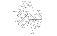
- the heating coil 9 and the other member Is within a range of 500 ⁇ m from the dividing line (for convenience, referred to as “predetermined section”), which is perpendicular to the straight line (dividing line) that virtually divides the line and passes through the center at the joining boundary from the dividing line.
- predetermined section a range of 500 ⁇ m from the dividing line (for convenience, referred to as “predetermined section”), which is perpendicular to the straight line (dividing line) that virtually divides the line and passes through the center at the joining boundary from the dividing line.
- a portion where the average Al concentration gradient is 0.1 wt% / ⁇ m or more means, for example, that the average Al concentration gradient is from the sheath 7 (control coil 10) side to the heating coil 9 side as shown in the graph of FIG.
- the Al concentration may vary over a section of 15 ⁇ m, and as shown in the graph of FIG. 11, the Al concentration varies in a curve from the sheath 7 (control coil 10) side to the heating coil 9 side. Also good. Also, as shown in the graph of FIG. 12, the Al concentration may change abruptly from the sheath 7 (control coil 10) side to the heating coil 9 side. In any case, it is intended that there should be a section in which the average Al concentration gradient is 0.1 wt% / ⁇ m or more in any of the gradient forming sections N1 and N2.
- the average Al concentration gradient varies depending on the welding method and welding conditions between the heat generating coil 9 and other adjacent members such as the sheath 7 and the control coil 10 when forming the joining region.
- a measure for providing a section in which the average Al concentration gradient in the joining region is 0.1 wt% / ⁇ m or more for example, resistance welding is employed, a relatively weak current is used, and a relatively short time is used.
- the amount of melting may be relatively reduced, such as by employing arc welding performed in step (b). However, since a decrease in the melting amount causes a decrease in the bonding strength, it is necessary to ensure a melting amount that can ensure a sufficient bonding strength.
- the tip of the heating coil 9 and the sheath 7 adjacent to the heating coil 9 are joined by melting and mixing each other's metal components, for example, by arc welding.
- a region (hereinafter referred to as a “tip-side joining portion”) 21 is formed, and the tip-side joining portion 21 has a predetermined direction from the sheath 7 (tip-side joining portion 21) side in the tip-side gradient forming section N1 toward the heat generating coil 9 side.
- a portion where the average Al concentration gradient in the section having a length of 15 ⁇ m along (A) is 0.1 wt% / ⁇ m or more can be provided.
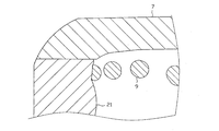
- the tip-side gradient forming section N1 is an outer shape of the tip-side joining portion 21 in a cross section passing through the axis C1 and the center of the tip of the heating coil 9 (that is, equal to the cross section of FIG. 8 in this embodiment).
- the vertical two of the boundary point connecting line segment R1 It refers to a section having a length of 500 ⁇ m along the equipartition line S ⁇ b> 1 on the side of the distal end side joining portion 21.
- the predetermined direction (A) refers to a direction in which the perpendicular bisector S1 of the boundary point connection line segment R1 extends.
- a metal tip member may be joined to the tip of the heating coil 9 and the tip member and the sheath 7 may be melted.
- the rear end of the heating coil 9 and the control coil 10 are melted and mixed with each other by, for example, arc welding, thereby joining the joining region (rear end side joining portion). ) 22 is formed, and the rear end side joining portion 22 is along a predetermined direction (B) from the control coil 10 (rear end side joining portion 22) side toward the heating coil 9 side in the rear end side gradient forming section N2.
- a portion having an average Al concentration gradient of 0.1 wt% / ⁇ m or more in a section having a length of 15 ⁇ m can be provided.
- the rear end side gradient forming section N2 is the outer shape of the heating coil 9 in a cross section passing through the axis C1 and the center of the rear end of the heating coil 9 (that is, in the present embodiment, equal to the cross section of FIG. 9).
- the rear end side perpendicular bisector S2 that is an equipartition line, from the center point X2 of the rear end side boundary point connecting line segment R2 to the heating coil 9 side and the control coil 10 (rear end side joining portion 22) side, respectively.
- both the coils 9, with the tip member interposed between the heating coil 9 and the control coil 10, similarly to the tip member that can be used to form the front end side joined portion 21. 10 and the chip member may be formed by melting.
- the heating coil 9 and the control coil 10 are joined by resistance welding, and the following is described from the control coil 10 side to the heating coil 9 side in the rear end side gradient forming section N3.
- a portion having an average Al concentration gradient of 0.1 wt% / ⁇ m or more in a section having a length of 15 ⁇ m along the direction in which the end-side vertical bisector S3 extends may be provided.
- the rear end side gradient forming section N3 is a rear end side joining portion of the virtual outline KG1 of the heating coil 9 before the rear end side joining portion is formed in a cross section passing through the axis C1 and the center of the rear end of the heating coil 9.
- the heating coil 9 is formed when the rear end side joined part is formed.
- Heat is generated from the center point X3 of the virtual intermediate line segment M along the rear-end-side vertical bisector S3 that is a vertical bisector of the virtual intermediate line segment M located in the middle of the virtual contact line segment KT2 that makes contact.
- Each of the sections has a length of 500 ⁇ m on the coil 9 side and the control coil 10 side.
- the two virtual contact line segments that overlap are set as the virtual intermediate line segment M.
- the rear end side joining portion 22 is formed so as to join the heating coil 9 and the control coil 10 apart from each other, but the form of the rear end side joining portion 22 is limited to this. is not.
- the form of the rear end side joining portion 22 may be a form in which both the heating coil 9 and the control coil 10 are joined together.
- the heating coil 9 and the control coil 10 are in contact between the rear end side second boundary point K4 and the contact end point K5 of the heating coil 9 and the control coil 10, but they are not welded. Is.
- sections having an average Al concentration gradient of 0.1 wt% / ⁇ m or more may be provided. In any one of them, a section in which the average Al concentration gradient is 0.1% by weight / ⁇ m or more may be provided.
- the heat generating coil 9 and nitrogen react directly without using a member connected to the heat generating coil 9.
- the division value x is relatively small such as “45 ⁇ x ⁇ 160”
- the volume of the heating coil 9 per unit surface area of the heating coil 9 is relatively small, so that it can be supplied per unit surface area of the heating coil 9.
- the amount of Al is small.
- the amount of Al is reduced to the extent that a continuous Al film cannot be formed even when used for a relatively short period of time due to repeated generation and peeling of the Al film on the surface layer of the heating coil 9.
- the area of the target coil region TK is sufficiently large, and the outer shape is close to a perfect circle, so that the necessary nitriding resistance can be obtained even if Al is not contained so much. Easy to realize.
- the heat generating coil 9 with “45 ⁇ x ⁇ 160” is more likely to infiltrate nitrogen and thus lowers the durability as compared with a heat generating coil having a relatively large cross-sectional area, a heat generating coil having a perfectly circular cross section, and the like. It can be said that it is effective when exhibiting a cross-sectional shape which is a further concern.
- y which is the Al content in the heating coil 9
- y is relatively large as “8 ⁇ y ⁇ 15”, so that it can be supplied per unit surface area of the heating coil 9.
- the amount of Al can be increased. Therefore, even if the generation and peeling of the Al film are repeated, a continuous Al film can be continuously formed over a relatively long period of time. As a result, the penetration of nitrogen into the heating coil 9 can be suppressed over a long period of time, and the life can be extended. Even if “45 ⁇ x ⁇ 160”, if “y ⁇ 8”, Al may be insufficient, and the above-described effects may not be sufficiently achieved. On the other hand, if “y> 15”, the workability may be reduced.
- the Al content is vital.
- the presence of the target coil region TK that satisfies 45 ⁇ x ⁇ 160 prevents nitrogen from entering the heating coil 9 for a long period of time. Can be prevented.
- a longer life is more easily achieved as a larger number of the plurality of coil regions K have a configuration as the target coil region TK.
- 70% or more of the plurality of coil regions K can be exemplified as the target coil region TK.
- the durability can be further improved and the service life can be dramatically extended.
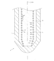
- the target coil region TK occupies 70% of the plurality of coil regions K, among the plurality of coil regions K, 10 is located on one side of the center axis X1 from the distal end of the sheath 7.
- the value x may be measured for each of the coil regions K1 to K10, and determination may be made based on whether or not the value x satisfies “45 ⁇ x ⁇ 160” in at least seven of the ten regions. It should be noted that the number x of regions for measuring the value x is sufficiently reliable even if it is about eight. However, a portion of the heating coil 9 that is joined to the sheath 7 is not handled as the coil region K.
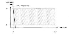
- the sheath heater 3 satisfies y ⁇ ( ⁇ 7/5) x + 78 as the feature 6 in addition to satisfying the condition of the feature 5.
- the x and y regions satisfying “45 ⁇ x ⁇ 160” and “8 ⁇ y ⁇ 15” in the feature 5 are regions with a dotted pattern in FIG.
- the x and y regions satisfying “y ⁇ ( ⁇ 7/5) x + 78” of the feature 6 are regions with a dotted pattern in FIG.
- the cross-sectional shape of the heating coil 9 may be deformed during manufacturing or the circumference of the heating coil 9 may be relatively large.
- the heating coil 9 may be reduced in diameter from the viewpoint of increasing the resistance value to achieve sufficient heat generation performance and keeping power consumption relatively low.
- the volume per unit surface area of the heat generating coil 9 decreases as the peripheral length of the heat generating coil 9 increases and the diameter of the heat generating coil 9 decreases.
- the value of x is relatively small (when x is less than 50)
- more Al is contained. Therefore, the intrusion of nitrogen into the heating coil 9 can be suppressed over a long period of time, and the effect of extending the life can be achieved more reliably.
- the relationship between x and y in the above-mentioned region is defined in the sense that the durability of the heat generating coil 9 having a relatively increased circumference while achieving a smaller diameter of the heat generating coil 9 is realized. It is more desirable to be within the range.
- the heating coil 9 includes manganese (Mn), silicon (Si), boron (B), vanadium (V), tantalum (Ta), titanium (Ti), zirconium. (Zr), hafnium (Hf), and at least one rare earth element such as cerium (Ce), and the total content thereof is 0.001 wt% or more and 5 wt% or less, and y ⁇ ( ⁇ / 20) x + 20 is preferably satisfied.
- Elements such as Mn and Si are elements that have less nitride formation free energy at 1000 ° C. than Cr nitride formation free energy at 1000 ° C., that is, elements that are more easily nitrided than Cr.
- an element such as Mn or Si functions as a nitrogen getter element to prevent nitridation of Cr, thereby further improving durability.
- rare earth elements such as Ti, Zr, Hf, and Ce are elements that are more easily nitrided than Al
- formation of AlN in the heating coil 9 can be effectively suppressed.
- lattice strain is generated in the metal structure such as Al forming the heating coil 9, so that a strain load is generated in the metal structure such as Al.
- Al is moved (supplied) to the surface layer of the heating coil 9 more quickly.
- the Al film is formed more reliably, the intrusion of nitrogen into the heat generating coil 9 can be more reliably suppressed.
- the total content of the nitrogen getter element and / or rare earth element is less than 0.001% by weight, the above-described effects may not be sufficiently achieved.
- the total content exceeds 5% by weight, the workability deteriorates and a relatively large nitride is generated inside the heating coil 9, and the corrosive gas enters from these as a starting point. There is a risk that.
- FIG. 3 the surface layer region 31 within 5 ⁇ m from the inner surface of the distal-side joining portion 21 between the distal end of the heating coil 9 and the sheath 7, and at least from the outer periphery of the distal end of the heating coil 9 to the distal-side joining portion 21. It is desirable that the aluminum content in the range of 100 ⁇ m along the inner surface is 3.5% by weight or more.
- the intrusion of nitrogen from the surface layer of the heat generating coil 9 and the intrusion of nitrogen from the tip side joining portion 21 in the vicinity of the heat generating coil 9 can be suppressed at a time, the generation of nitride inside the heat generating coil 9 is further improved. This can be surely prevented, and as a result, the durability can be dramatically improved and the life can be extended.
- the Al content in the sheath 7 is 3.5% by weight or more.
- the Al content in the tip-side joining portion 21 between the heating coil 9 and the sheath 7 can be reliably set to 3.5% by weight or more. Accordingly, an Al-based film can be formed over the entire surface layer of the distal-end-side bonded portion 21, and an Al-based film can also be formed in the sheath 7. As a result, the penetration of nitrogen into the heating coil 9 can be more effectively suppressed, and the durability can be further improved.
- the feature 9 when the feature 9 is satisfied, as the feature 11, at least in the surface layer region 31 of the distal end side bonded portion 21 within the range of 100 ⁇ m from the outer periphery of the distal end of the heating coil 9 to the inner surface of the distal side bonded portion 21 It is desirable that there is a region containing at least one element having a lower nitride formation free energy at 1000 ° C. than that of chromium (Cr) at 1000 ° C.
- the heating coil 9 contains Cr, the resistance value of the heating coil 9 can be increased sufficiently. For this reason, sufficient heat generation performance can be realized without excessively reducing the diameter of the heating coil 9. Further, since it is not necessary to reduce the diameter of the heating coil 9 excessively, the heating coil 9 can be made relatively thick, and as a result, the durability of the heating coil 9 can be improved. On the other hand, since Cr is an element that is relatively easily nitrided, there is a concern that the nitriding of Cr proceeds and the durability of the heat generating coil 9 is lowered.
- Cr can be melted in the tip-side joined portion 21 by forming the tip-side joined portion 21, but when the Cr is nitrided, Al-based in the surface layer of the tip-side joined portion 21 in the vicinity of the heating coil 9. There is a possibility that Cr nitride is scattered in the coating, and a discontinuous Al-based coating is formed. As a result, there is a concern that the penetration of nitrogen into the heating coil 9 cannot be sufficiently suppressed.
- nitride at 1000 ° C. is more than the free energy of formation of nitride of chromium (Cr) at 1000 ° C., at least within the range of 100 ⁇ m from the outer periphery of the tip of the heating coil 9 to the inner surface of the tip-side joining portion 21. If there is a region containing at least one element with low generation free energy, the element functions as a so-called nitrogen getter element in a high temperature environment (1000 ° C.) assuming that the sheath heater 3 is used, and the heating coil 9 Nitriding of Cr inside can be prevented.
- the nitrogen getter element include rare earth elements such as manganese, silicon, boron, vanadium, tantalum, magnesium, titanium, zirconium, hafnium, and cerium.
- the rear end of the heating coil 9 and the control coil 10 as shown in FIG. It is desirable that the aluminum content in the side joining portion 22 is 3.5% by weight or more.
- the heating coil 9 contains a sufficient amount of Al, an Al-based film can be formed on the surface layer of the heating coil 9 and nitrogen intrusion from the surface layer of the heating coil 9 can be prevented. Furthermore, if the Al content in the rear end side bonded portion 21 is 3.5% by weight or more, an Al-based film can be formed on the surface layer of the rear end side bonded portion 21. Thereby, the penetration
- the rear end side bonded portion 22 includes a region containing at least one element having a nitride free energy at 1000 ° C. lower than that at 1000 ° C. It is desirable to exist.
- the heating coil 9 contains Cr, the resistance value of the heating coil 9 can be sufficiently increased. For this reason, sufficient heat generation performance can be realized without excessively reducing the diameter of the heating coil 9. Further, since it is not necessary to reduce the diameter of the heating coil 9 excessively, the heating coil 9 can be made relatively thick, and as a result, the durability of the heating coil 9 can be improved. On the other hand, since Cr is an element that is relatively easily nitrided, there is a concern that the nitriding of Cr proceeds and the durability of the heat generating coil 9 is lowered.
- Cr can be melted in the rear end side joining portion 22 by forming the rear end side joining portion 22, but when the Cr is nitrided, the Al-based coating on the surface layer of the rear end side joining portion 22 is formed. There is a possibility that Cr nitride is scattered and the Al-based film becomes discontinuous.
- the sheath heater In a high temperature environment (1000 ° C.) that is assumed to be used, the element functions as a so-called nitrogen getter element, and nitriding of Cr inside the heating coil 9 can be prevented.
- a continuous Al-based film can be formed at the rear end side bonded portion 22, it is possible to more effectively prevent nitrogen from entering.
- the heating coil 9 contains Cr
- zirconium (Zr) is contained in an amount of 0.005 wt% to 2 wt%
- titanium (Ti) is contained in an amount of 0.005 wt% to 5 wt%.
- the heating coil 9 contains a predetermined amount of Zr or Ti that functions as a nitrogen getter element, nitriding of Cr can be more reliably suppressed.
- the content of Zr or Ti is less than 0.005% by weight, there is a possibility that Cr nitridation cannot be sufficiently suppressed.
- the content of Zr exceeds 2% by weight or when the content of Ti exceeds 5% by weight, it may be difficult to process the heating coil 9.
- the glow plug 1 having the above configuration can be manufactured by the following method.
- part which is not specified in particular it manufactures by a conventionally well-known method.
- a resistance heating wire of an Fe—Al alloy containing 5 wt% or more and 20 wt% or less of Cr and more than 8 wt% and 15 wt% or less of Al is processed into a coil shape to obtain a heating coil 9. .
- both the coils 9 and 10 are joined by forming the rear end side joining portion 22 in which the alloy components constituting both the coils 9 and 10 are melted by arc welding.
- predetermined welding conditions for example, 30 A for 100 ms
- Arc welding is performed, for example, by blowing an arc and performing welding.
- the tip of the middle shaft 8 and the heating coil 9 and the control coil integrated with the middle shaft 8 are formed in a cylindrical sheath 7 having a larger diameter than the final dimension by the machining allowance and the tip is not closed. 10 are arranged. Then, for example, the tip portion of the sheath 7 is closed by arc welding, and the metal constituting the sheath 7 and the heating coil 9 are configured to join the tip portion of the sheath 7 and the tip portion of the heating coil 9. Metals are melted together to form the tip-side joining portion 21.
- an arc for 300 ms at 90 A is used. Arc welding is performed, for example, by blowing an arc for 50 ms at 40 A and then welding.
- the sheath 7 is filled with the insulating powder 11, the sheath 7 is subjected to swaging. Thereby, the sheath 7 having the large diameter portion 7b is formed, and the sheath 7 is integrated with the middle shaft 8 to complete the sheath heater 3.
- the sheath heater 3 formed as described above is press-fitted and fixed in the shaft hole 4 of the housing 2, and the O-ring 12, the insulating bush 13, and the like are fitted into the middle shaft 8 at the rear end portion of the housing 2, The glow plug 1 is completed.
- Examples Samples Nos. 1, 3 to 5, 7, and 8, Comparative Examples: Samples Nos. 2, 6, and 9 were produced as follows. First, raw materials are weighed and mixed to produce a molten alloy. Next, a ⁇ 30 mm cylindrical ingot was formed by hot working, and a ⁇ 0.3 mm strand was produced by drawing. The produced wire was coiled by a conventionally known method to obtain a coil shape. Sample No. The compositions of 1 to 9 are shown in Table 1. Sample No. For 1 to 9, Cr was contained in stages, and the blending amount of Al was changed. The ratio of each composition shown in Table 1 is% by weight, and the total of each composition is 100% by weight. The composition was analyzed using EPMA for the prepared samples (conditions: beam diameter: 10 ⁇ m, voltage: 20 kV, current: 2.5 ⁇ 10 ⁇ 8 A).
- each sample was subjected to a thermal durability test.
- each sample was placed in an electric furnace capable of gas replacement and maintained at 1200 ° C. for 5 hours.
- the atmosphere inside the electric furnace has an initial oxygen partial pressure of 0.2 ⁇ 10 5 Pa, and after 3 minutes, 1.0 ⁇ 10 ⁇ 13 Pa.
- the test was performed using nitrogen gas containing a reducing gas such as CO (carbon monoxide) and H 2 (hydrogen) for adjusting the oxygen partial pressure.
- the sheath surface temperature is as high as 900 ° C. to 1000 ° C. during use.
- a temperature difference of about 100 ° C. at maximum occurs between the surface temperature of the sheath where the heating coil is located and the surface temperature of the sheath where the control coil is located.
- a temperature difference of 100 ° C. or more is also generated between the surface temperature and the heat generating coil and the control coil housed inside. Taking these and temperature errors into consideration, in order to evaluate the durability of the heat generating coil at high temperatures, if it is set to 1200 ° C., it is possible to perform a test assuming a use state.
- each sample was embedded in the resin block P1, and the resin block P1 and the sample were cut and polished along the longitudinal direction C2 of the sample (of course, only polishing without cutting) May be done).
- rough polishing was performed with SiC water-resistant polishing paper (# 1500), and then mirror finishing was performed with 1 ⁇ m of diamond paste.
- SiC water-resistant polishing paper # 1500
- mirror finishing was performed with 1 ⁇ m of diamond paste.
- the sample has a diameter of 0.3 mm, it is desirable to suppress polishing to the inside of the sample about 0.1 to 0.15 mm.
- the mirror-finished sample was degreased and washed with an organic solvent such as acetone, and the structure was observed with a metal microscope, SEM, or the like, and the thickness of the altered portion on the surface layer of the sample was measured.
- Samples 2 and 4 are shown in FIGS. 4 and 5 as representative examples of the observed images.
- the element mapping using EPMA X-ray microanalyzer
- the film was an oxide or nitride mainly composed of Al, and was an oxide or nitride mixed with “Al”, Al and Cr in the “surface layer product” column. The thing is indicated as “Al, Cr”.
- Table 1 shows the measurement and analysis results of the thickness of the surface layer portion including the film and the properties of the surface layer portion.
- Sample No. for 1 to 9 the altered surface layer portions were only Al or a mixed oxide film and nitride film of Al and Cr.
- Cr 2 N which is inferior in protective properties, was formed in a layer directly under the Al 2 O 3 film on the surface layer, and nitrogen entered the inside.
- Sample No. with a Cr content exceeding 20% by weight was used.
- a film in which Al 2 O 3 , AlN, and Cr 2 N were mixed was formed on the surface layer. For this reason, the film was not formed as a good film, and internal nitridation occurred.
- the Cr 2 N coating has a high nitrogen gas permeability and could not effectively prevent the penetration of nitrogen into the interior.
- a Cr 2 N film is formed, a dense Al 2 O 3 film is not continuously formed, and the Cr 2 N film and the Al 2 O 3 film are adjacent to each other in pieces. We infer that it has been closed.
- the nitrogen partial pressure is higher than the oxygen partial pressure in the partial pressure ratio as in the glow plug sheath, and the oxygen partial pressure gradually decreases (oxidation of the heating coil causes In an environment where oxygen is consumed, the heating coil has a composition of Cr 5 wt% or more and 20 wt% or less and Al more than 8 wt% and 15 wt% or less, thereby generating granular AlN and Cr. It was confirmed that it was possible to suppress the generation of 2 N to improve the durability of the heat generating coil, and to achieve high durability as a sheath heater and thus a glow plug. (Evaluation test 2)
- Sample No. 5 having a Cr content of 5 wt% to 20 wt% and an Al content of more than 8 wt% to 15 wt% or less.
- No. 7 although the durability was 6000 cycles or more, Cr 2 N was easily generated in the film formed on the outer surface, and in the above evaluation test 1, the mixture of Al 2 O 3 and Cr 2 N was oxidized. As a film and a nitride film have been formed, the durability tends to be difficult compared to other samples (for example, sample No.
- the control coil was made of Co-25 wt% Ni-4 wt% Fe, and the sheath was made of Inconel®601.
- each sheath heater was subjected to a thermal durability test using the same apparatus as in Evaluation Test 1. These five sheath heaters were completed as sheath heaters for testing, and then the portion including the sealing member at the rear end of the sheath was removed by cutting so that the inside and the outside of the sheath were not airtight. In the test, each sample was held at 1200 ° C. for 20 hours. Sample No. Two of 2-1 and 5-1 were equal to the air atmosphere, and the oxygen partial pressure was 0.2 ⁇ 10 5 Pa. On the other hand, sample no. For the three pieces of 2-2, 5-2 and 5-3, the oxygen partial pressure was set to 1.0 ⁇ 10 ⁇ 13 Pa assuming the atmosphere inside the sheath used as a glow plug.
- each sample After holding in an electric furnace for 20 hours, each sample is disassembled and cut, and cross sections of the heating coil, control coil, and sheath are observed.
- cross section each member to be observed is embedded in a resin block and observed in the same manner as in the evaluation test 1 (see FIG. 6). The observation results are shown in Table 3.
- Sample No. 2-1 and 5-1 compare the degree of nitridation due to the difference in the composition of the heating coil in an air atmosphere, that is, an environment where oxygen is sufficiently present and the atmosphere is not excessive with nitrogen. According to this, sample No. of the comparative example. No. 2-1, sample No. in the embodiment of the present invention. Even in the case of 5-1, the degree of nitridation of the heating coil does not progress to 0%, there is no particular difference between them, and it can be determined that both have excellent durability.
- the thickness of the oxide film on the control coil and the thickness of the oxide film on the inner peripheral surface of the sheath were determined as Sample No. In Sample No. 2-1, the thickness is 113 ⁇ m and 17 ⁇ m. In 5-1, it was 117 ⁇ m and 19 ⁇ m.
- sample No. 1 that assumed the inside of the sheath where oxygen was not sufficiently present and the atmosphere was excessive in nitrogen.
- Sample No. as a comparative example is shown.
- the nitriding degree of the heating coil proceeds to 82%
- sample No. As for 5-2 and 5-3 the degree of nitriding did not proceed as 0%, and it can be judged that the nitriding degree has excellent durability. Therefore, it was verified that the heating coil 9 achieves excellent durability in a sheath having an internal atmosphere in which the nitrogen partial pressure is larger than the oxygen partial pressure.
- the thickness of the oxide film of the control coil was determined as Sample No.
- Sample numbers of glow plugs with various changes in gradient. 1 to 28 were produced.
- the front end side joining portion of the heating coil was formed by arc welding or resistance welding
- the rear end side joining portion of the heating coil was formed by the same welding method and the same welding conditions for each sample. Further, the heating coil is subjected to a diameter reduction process as necessary so that the heating coil has a predetermined resistance value.
- Table 5 shows the contents of Al, Cr, etc.
- the composition ratio distribution of the heating coil in each sample when focusing on the contents of Al and Cr is shown in the triangular diagram of FIG.
- the left oblique side of the triangular diagram of FIG. 15 indicates the Cr content (% by weight)
- the right oblique side indicates the Al content (% by weight).
- the “average Al concentration gradient” in Table 5 is referred to as (reference), in addition to the samples subjected to the durability evaluation test, having the same composition as each sample, and the same welding method and This is because the average Al concentration gradient obtained by analyzing the gradient forming section is shown for the samples produced according to the welding conditions (that is, strictly different from each sample). Therefore, the “average Al concentration gradient” in the table may not be exactly equal to the “average Al concentration gradient” actually possessed by each sample, but is very close to the actual value. Is.
- the average Al concentration gradient was measured as follows. First, as shown in FIG. 13, after cutting the sample so as to pass through the sheath axis and the center of the heating coil tip, the cut surface is observed, and the outer contour line G1 of the distal end side joining portion 21 and the outer contour line G2 of the heating coil. (The left side portion in FIG. 13 is the tip side joining portion 21 and the right side portion is the heating coil 9).
- the 500 ⁇ m section is defined as a slope forming section N1, and EPMA is used at an arbitrary interval with respect to the slope forming section, and a section having a relatively large change in Al concentration (detail measurement target section) is specified (that is, Al concentration) I picked up a section with a relatively large change amount).
- the Al concentration is plotted with black square points, and the Al change rate is plotted with black triangle points. And among the Al change rates of each section, the maximum value was used as the average Al concentration gradient of the sample. That is, the average Al concentration gradient of the sample was 0.259% by weight / ⁇ m, which is the maximum value among the Al change rates.
- the portion where the change in Al concentration almost disappeared compared to the adjacent point is the boundary between the heating coil and the tip side joining portion (the boundary line in FIG. 13). )Met.
- each sample was subjected to a durability evaluation test.
- the durability evaluation test the number of cycles until the heating coil was disconnected (number of disconnection cycles) was measured by energizing at 11V for 6 seconds and then energizing at 14V for 180 seconds as one cycle.
- “B” is evaluated as having excellent durability
- samples having a disconnection cycle number of 7000 cycles or more durability is extremely excellent.
- A was evaluated.
- the sample having a number of disconnection cycles of less than 6000 cycles was evaluated as “C” because the durability was not good.
- Al is contained exceeding 15% by weight and when the total content of nitrogen getter elements is contained exceeding 5% by weight, the heating coil may be reduced to a predetermined diameter. Since it was difficult, the evaluation test was not performed.
- Table 5 The test results are shown in Table 5.
- the number of disconnection cycles was 6000 cycles or more, and excellent durability was confirmed. This is because when Al is contained, a coating such as AlN is formed on the surface of the heating coil, and when the heating coil contains more than 8 wt% and not more than 15 wt%, the average Al concentration gradient Is 0.1% by weight / ⁇ m or more, and AlN is formed one after another by nitrogen that has entered and Al that has been supplied without a shortage of Al, and a wide range of strong AlN layers are formed.
- the Al content exceeds 8% by weight and is 15% by weight or less
- the Cr content is 5% by weight or more and 20% by weight or less, that is, a region surrounded by a thick line in FIG.
- a sample No. 1 having an average Al concentration gradient of 0.1 wt% / ⁇ m or more is formed. 7 to 28 were found to have very excellent durability. This is probably because the heat generation coil could be made relatively thick due to the inclusion of Cr, and the durability could be further improved. Further, in this case, sample No. with a Cr content of 15 wt% or less was used. For 10 to 28, the number of disconnection cycles was 8000 cycles or more, and a further improvement in durability was observed.
- sample No. 1 containing nitrogen getter elements such as Hf, Zr, Ti, Si, Mn and the like in an amount of 0.001 wt% to 5 wt%.
- sample Nos. 22 to 28 sample Nos. 1 and 2 with the same Al and Cr content and average Al concentration gradient were used. Compared to 15, further improvement in durability was observed. This is because the nitridation of Cr is suppressed by the element and metal distortion is generated in the metal structure of the heat generating coil, so that Al moves more quickly, and thus the AlN layer is more reliably obtained. This is thought to be due to the fact that it was formed. (Evaluation Test 5)
- the rear end side first boundary that is the boundary point between the outer shape line of the heating coil and the outer shape line of the joined portion on the rear end side
- a section having a length of 500 ⁇ m on each of the heating coil side and the control coil side was defined as a gradient forming section.
- sample No. 1 containing Al in excess of 8 wt% and 15 wt% or less and having an average Al concentration gradient of 0.1 wt% / ⁇ m or more. It was revealed that 44 to 60 were excellent in durability. This is considered to be due to the fact that a strong AlN layer covering a wide range was formed at the rear end side joining portion, and nitrogen intrusion from the rear end side joining portion into the heating coil was more reliably suppressed.
- the number of disconnection cycles was 8000 or more, and a further improvement in durability was observed. However, the sample No. in which Cr exceeded 20% by weight.
- sample No. 44 the same amount of Al and no more than 20% by weight of Cr sample No. As a result, the number of disconnection cycles was slightly shorter than 45.
- Sample Nos. 56 to 60 Sample Nos. With the same Al and Cr content and average Al concentration gradient were used. It was confirmed that the durability was further improved as compared with 48.
- the heat generating coil contains Al exceeding 8% by weight and 15% by weight or less, and the section in which the average Al concentration gradient in the joining region is 0.1% by weight / ⁇ m or more is provided. It can be said that the nitriding of the steel can be effectively suppressed, and as a result, the durability can be sufficiently improved. Further, when Cr is contained in an amount of 5 wt% or more and 20 wt% or less, the number of disconnection cycles becomes 7000 cycles or more, and it can be said that very excellent durability can be realized. In this case, it can be said that the durability can be improved more effectively by setting the Cr content to 15% by weight or less. In addition, it can be said that the durability can be further improved by containing 0.001 wt% or more and 5 wt% or less of a nitrogen getter element such as Hf or Zr. (Evaluation Test 6)
- Sample No. is obtained by joining the heat generating coil and the sheath by variously changing the welding method (arc welding or resistance welding) and welding conditions (current value and discharge time). 1 to 18 were produced.
- the heating coil is composed of Fe as a main component, Cr containing 9.4% by weight, and Al more than 8% by weight and 15% by weight or less.
- a sheath made of Fe-25Cr-20Ni (SUS 310s) or Ni-23Cr-14.4Fe-1.4Al [Inconel 601 (registered trademark)] was used.
- arc welding after arcing at 90 A for 300 ms, welding was performed by blowing arc at 40 A for 50 ms.
- the average Al concentration gradient in the joining region between the heating coil and the sheath was measured.
- EPMA was used to irradiate a beam having a beam diameter of 3 ⁇ m every 3 ⁇ m to the gradient forming section, and the Al concentration of each part was measured.
- average Al concentration gradients were calculated for a plurality of sections having a length of 15 ⁇ m, and the maximum value among them was used as the average Al concentration gradient of each sample.
- Table 7 shows the average Al concentration gradient when the welding method is arc welding or resistance welding.
- sample No. welded by arc welding. 1 to 6 and sample No. 1 welded by resistance welding. 7 to 12 it was possible to form a section in which the average Al concentration gradient was 0.1 wt% / ⁇ m or more.
- Samples Nos. 7 to 12 were welded by arc welding. It was found that the average Al concentration gradient can be increased as compared with 1 to 6. This is because a steeper Al concentration gradient was formed because the amount of melting at the tip side joining portion formed by resistance welding was smaller than the amount of melting at the tip side joining portion formed by arc welding. It is believed that there is.
- Table 8 shows the average Al concentration gradient when the welding conditions (current value and discharge time) are variously changed in arc welding.
- Sample No. is obtained by joining the heat generating coil and the control coil by variously changing the welding method (arc welding or resistance welding) and welding conditions (current value and discharge time). 1 to 9 were produced. Here, the same heating coil as that described above was used.
- the control coil was composed of cobalt (Co) as a main component and Ni and Fe. In arc welding, welding is performed by blowing an arc at 30 A for 100 ms, while in resistance welding, welding is performed by energizing for 10 ms at 1.5 kA.
- the average Al concentration gradient in the junction region between the heating coil and the control coil was measured in the same manner as described above.
- Table 9 shows the average Al concentration gradient when the welding method is arc welding or resistance welding.
- Samples Nos. 5, 6, 7, and 8 were able to form sections with an average Al concentration gradient of 0.1 wt% / ⁇ m or more.
- Samples Nos. 5, 6, 7, and 8 were welded by arc welding. It was found that the average Al concentration gradient can be increased compared to 1, 2, 3, and 4. This is considered to be because the melting amount of the rear end side joining portion formed by resistance welding is relatively small as compared with the melting amount of the rear end side joining portion formed by arc welding.
- Table 10 shows the average Al concentration gradient when the welding conditions (current value, discharge time) are variously changed in arc welding.
- 9 is a sample No. 9 welded by blowing an arc at 30 A for 100 ms. It was found that the average Al concentration gradient was less than 0.1% by weight / ⁇ m even though the material of No. 1 and the heating coil and the like were the same. This is presumably because the Al concentration gradient became more gradual as a result of the amount of melting at the rear end side joining portion being too large.
- the circumference and area of the target coil area TK in each sample were measured as follows. That is, first, as in the above-described FIG. 6, the sheath 7 of each sample was embedded in the resin piece P ⁇ b> 1 and cut along the longitudinal direction of the sheath 7. More specifically, the sheath 7 (heat generating coil) was cut along the center axis C2 of the sheath 7 so as to include the center axis of the heat generating coil in the sheath 7, and the cut surface was imaged. And in calculating
- the circumference of the target coil region TK was calculated by multiplying the number of pixels by the actual length per pixel calculated in advance. Further, in obtaining the area of the target coil region TK, the image pickup data was converted into two gradations by a computer, thereby extracting the target coil region TK and measuring the number of pixels occupied by the target coil region TK. Then, the area of the target coil region TK was calculated by multiplying the measured number of pixels by the actual area per pixel calculated in advance.
- the Al content of the heating coil of each sample was measured by irradiating a predetermined part of the heating coil with a beam (voltage value 20 kV, current value 2.5 ⁇ 10 ⁇ 8 A) using EPMA.
- the content of additive elements in each sample was measured by ICP analysis.
- each sample was energized at 11V for 5 seconds, then energized at 14V for 100 seconds, and then air-cooled for 180 seconds, and the number of cycles until the heating coil was disconnected (number of disconnected cycles).
- “B” is evaluated as having excellent durability
- samples having a disconnection cycle number of 8000 cycles or more durability is extremely excellent.
- A was evaluated.
- the sample having a number of disconnection cycles of less than 7500 cycles was evaluated as “C” because the durability was not good.
- thermocouple Pt / Pt-Rh
- Table 11 shows the results of the durability evaluation test and the temperature rise characteristic evaluation test.
- Al is contained in an amount exceeding 15% by weight, and when the total content of nitrogen getter elements exceeds 5% by weight, it is difficult to process the heating coil. Did not do.
- the cross section of the fourth heating coil from the distal end side of the sheath was set as the target coil region TK, and the value x for the target coil region TK was calculated by the above calculation method.
- the sample No. configured to satisfy the expression “y ⁇ ( ⁇ 7/5) x + 78”.
- the number of disconnection cycles was 8000 cycles or more, and it was found that the samples had very excellent durability. This is considered to be due to the inclusion of a more appropriate amount of Al corresponding to the value of x that changes variously due to the increase in the peripheral length of the heat generating coil, the reduction in diameter, and the like.
- Nos. 19 to 23 are sample Nos. That do not contain a nitrogen getter element and have the same x and Al and Cr contents.
- a further improvement in durability was observed compared with 14-16. This is because the nitrogen getter element suppresses the nitridation of Cr and causes metal distortion in the metal structure of the heat generating coil, so that Al moves more quickly, and thus the Al film becomes more This is considered to be due to the more reliable formation.
- sample No. 1 containing a nitrogen getter element and configured to satisfy the expression “y ⁇ ( ⁇ 1/20) x + 20”.
- Samples Nos. 19 to 22 had a disconnection cycle number of 14,000 cycles or more, the values of x were the same, and sample Nos. Compared to 16, it was found to have comparable durability. That is, by containing the nitrogen getter element and satisfying the formula of “y ⁇ ( ⁇ 1/20) x + 20”, it is possible to suppress the Al content while realizing excellent durability. It can be said that workability can be improved.
- Sample No. with a Cr content of less than 5% by weight About 24 and 25, although it had the outstanding durability, it turned out that temperature rising performance is somewhat inadequate.
- Sample No. with a Cr content exceeding 20% by weight was used.
- sample No. 26 with a Cr content of 5 wt% or more and 20 wt% or less is used. Compared with 12, 27 to 30, it was recognized that the durability slightly decreased. Accordingly, it can be said that the Cr content is more preferably 5 wt% or more and 20 wt% or less in order to maintain a very excellent durability while realizing a sufficient temperature raising performance.
- sample no. 9 and sample no. The following facts became clear when 12 was compared in detail.
- the two samples have the same composition, but have a slight difference in the coil shape by different swaging methods for the sheath.
- the result of measuring and calculating the value x for each of the eight coil regions K1 to K8 from the coil region K1 located at the forefront to the eighth coil region K8 on the rear end side is shown as Sample No. 9 is shown in Table 12, and sample No. 12 is shown in Table 13.
- composition ratio of the heat generating coil, the composition ratio of the sheath, and the surface layer region 31 of the distal end side joining portion 21 (see FIG. 25; the surface layer region 31 of the distal end side joining portion 21 is the heating coil 9 side of the distal end side joining portion 21
- surface Al length The average length (referred to as “surface Al length”) from the outer periphery of the tip of the heating coil of the portion where the Al content is 3.5% by weight or more is represented. Changed glow plug sample No. 1 to 13 were produced.
- Fe-22Cr-5.3Al [Kantal (registered trademark)], Fe-26Cr-7.5Al [Pyromax (registered trademark)], or Kanthal as a nitrogen getter element An alloy containing Zr or Ti was used.
- the alloys constituting the sheath include Fe-25Cr-20Ni (SUS 310), Ni-23Cr-14.4Fe-1.4Al [Inconel 601 (registered trademark)], Ni-18.7Co-14.5Cr- 5Mo-4Al-3Ti (Udimet 700) or Ni-15Cr-14Co-5Al-4Ti [Nimonic 115 (registered trademark)] was used.
- the heat generating coil and the sheath are directly joined to form a tip side joining portion.
- the heating coil and sheath are joined via a tip member containing Fe as a main component and Al in an amount of 2% by weight, 3% by weight, or 10% by weight.
- a junction site was formed. Furthermore, sample no. In No. 4, after the end of the heating coil 2 mm was plated with 100 ⁇ m thick Al, In No. 7, the heating coil tip 2 mm was plated with Al having a thickness of 200 ⁇ m, and then the heating coil and the sheath were joined to form a tip side joining portion.
- the sample No. with a surface layer Al length of less than 100 ⁇ m is used.
- the number of disconnection cycles was less than 7000, and it was revealed that the durability was not very good. This is because even if an Al-based film is formed on the surface of the heating coil and nitrogen intrusion from the surface of the heating coil can be suppressed, a sufficient Al-based film is not formed at the tip-side joining site near the tip of the heating coil, As a result, it is considered that the entry of nitrogen could not be sufficiently prevented.
- the number of disconnection cycles was 7000 or more, and it was found that excellent durability could be exhibited.
- the Al-based coating is also applied to the tip side joining portion in the vicinity of the heating coil (in the range of at least 100 ⁇ m along the inner surface of the tip side joining portion 21 from the tip outer periphery GS in FIG. This is considered to be due to the fact that nitrogen intrusion could be effectively suppressed.
- Nos. 8, 11, and 12 had an Al content of 3.5% by weight or more in the entire region of the tip-side joining portion, and could achieve extremely excellent durability performance.
- sample No. 1 was formed by joining through a tip member containing 10% by weight of Al to form a tip side joining portion.
- the surface Al length was as long as 500 ⁇ m, and excellent durability performance could be realized.
- sample Nos. 1 and 2 containing Ti and Zr in the heating coil For Nos. 9 and 10, the number of disconnection cycles is 8000 cycles or more, and the composition ratio of the heating coil is substantially equal except for the presence or absence of Ti or Zr. Compared with 6, a further improvement in durability was observed. This is considered to be due to the following reason. That is, the heat generating coil containing Zr or Ti and the sheath are melt-bonded, so that at least from the outer periphery of the front end of the heat generating coil along the inner surface of the front end side joining portion of the surface layer region of the front end side joining portion. A region containing Ti or Zr exists in the range of 100 ⁇ m.
- As the control coil a Y—Ni alloy (an alloy based on Ni and containing Y (yttrium) in a minute amount) or a Y—Ni-3Al alloy was used.
- Fe-22Cr-5.3Al (Kantal) was used as the heating coil. In No. 24, Kanthal contained Zr. Sample No. 21, 22, and 24, the heating coil and the control coil are directly joined to form a rear end side joined portion.
- the heat generating coil and the control coil were joined via a chip member containing Fe as a main component and containing 10% by weight of Al, thereby forming a rear end side joining portion.
- the number of disconnection cycles was 7000 or more, and it was revealed that excellent durability performance could be realized. This is considered to be due to the fact that the penetration of nitrogen into the inside of the heating coil could be effectively suppressed by the formation of the Al-based film on the surface layer of the rear end side bonded portion in addition to the heating coil surface layer.
- sample No. with Zr contained in the heating coil For sample No. 24, the number of disconnection cycles was 8000 cycles or more, and the composition ratios of the heating coil and the control coil were substantially equal except for the presence or absence of nitrogen getter element. It was found that the durability could be further improved compared to 22. This is because the heat-generating coil containing Zr and the control coil are melt-bonded, so that there is a region containing Zr in the rear end side bonded portion, and the Zr functions as a nitrogen getter element, Cr This is considered to be because the nitriding of nitrogen was suppressed, and the continuous Al-based film was formed at the joining portion on the rear end side, so that intrusion of nitrogen could be prevented more effectively.
- sample No. 1 was formed after a chip member containing sufficient Al was interposed between the heating coil and the control coil.
- No. 23 was able to prevent nitrogen intrusion more effectively and was the most excellent number of disconnection cycles among the four samples.
- the said evaluation test performs a comparison within each evaluation test, and it is not necessarily effective to determine superiority or inferiority by simply comparing the results of samples in different evaluation tests. This is because the test conditions and criteria for each evaluation test are different.
- the glow plug 1 including the sheath heater 3 is described as a specific example, but the sheath heater 3 is used as a heating means for heating a liquid or gas in various fields other than the glow plug 1 for a diesel engine. May be.
Landscapes
- Engineering & Computer Science (AREA)
- Chemical & Material Sciences (AREA)
- Ceramic Engineering (AREA)
- Combustion & Propulsion (AREA)
- Mechanical Engineering (AREA)
- General Engineering & Computer Science (AREA)
- Resistance Heating (AREA)
Abstract
L'invention concerne un élément de chauffage de gaine comprenant une gaine métallique tubulaire composée principalement de nickel ou de fer, fermée sur l'extrémité avant et s'étendant dans la direction axiale, une bobine génératrice de chaleur ménagée dans la gaine le long de la direction axiale et dont l'extrémité avant est connectée électriquement à la gaine, un élément conducteur placé dans la gaine et dont l'extrémité avant est connectée électriquement avec la bobine génératrice de chaleur et dont l'extrémité arrière se projette vers l'extrémité arrière de la gaine, une poudre isolante remplissant la périphérie de la bobine génératrice de chaleur dans la gaine, et un élément d'étanchéité fermant l'extrémité arrière de la gaine. L'élément de chauffage de gaine est caractérisé en ce que l'atmosphère interne de la gaine fermée par l'élément d'étanchéité a une pression partielle d'azote supérieure à la pression partielle d'oxygène et en ce que la bobine génératrice de chaleur, principalement composée de fer, contient entre 5 et 20 % en poids de chrome, et entre 8 et 15 % en poids d'aluminium. Cet élément de chauffage de gaine peut s'utiliser de façon appropriée dans une lampe à décharge, et analogue.
Applications Claiming Priority (8)
| Application Number | Priority Date | Filing Date | Title |
|---|---|---|---|
| JP2007-338548 | 2007-12-28 | ||
| JP2007-338563 | 2007-12-28 | ||
| JP2007340655A JP2009162409A (ja) | 2007-12-28 | 2007-12-28 | グロープラグ |
| JP2007338563A JP2009158432A (ja) | 2007-12-28 | 2007-12-28 | シースヒータ及びグロープラグ |
| JP2007338552A JP2009158431A (ja) | 2007-12-28 | 2007-12-28 | シースヒータ及びグロープラグ |
| JP2007-340655 | 2007-12-28 | ||
| JP2007-338552 | 2007-12-28 | ||
| JP2007338548A JP2009156560A (ja) | 2007-12-28 | 2007-12-28 | シースヒータ及びグロープラグ |
Publications (1)
| Publication Number | Publication Date |
|---|---|
| WO2009084453A1 true WO2009084453A1 (fr) | 2009-07-09 |
Family
ID=40824173
Family Applications (1)
| Application Number | Title | Priority Date | Filing Date |
|---|---|---|---|
| PCT/JP2008/073086 Ceased WO2009084453A1 (fr) | 2007-12-28 | 2008-12-18 | Elément de chauffage de gaine et bougie de préchauffage |
Country Status (1)
| Country | Link |
|---|---|
| WO (1) | WO2009084453A1 (fr) |
Cited By (7)
| Publication number | Priority date | Publication date | Assignee | Title |
|---|---|---|---|---|
| WO2011162074A1 (fr) * | 2010-06-22 | 2011-12-29 | 日本特殊陶業株式会社 | Bougie de préchauffage, procédé de production associé et dispositif de chauffage |
| CN103361595A (zh) * | 2012-03-27 | 2013-10-23 | 香港生产力促进局 | 使用等离子体浸没离子注入(piii)对活塞环进行渗氮的装置 |
| WO2014206847A1 (fr) * | 2013-06-26 | 2014-12-31 | Robert Bosch Gmbh | Tube incandescent pour une bougie-crayon de prechauffage reglable |
| JP2015096786A (ja) * | 2013-11-15 | 2015-05-21 | 日本特殊陶業株式会社 | グロープラグ |
| JP2016508181A (ja) * | 2012-12-10 | 2016-03-17 | サエス・ゲッターズ・エッセ・ピ・ア | 反応性ガスへの暴露の後に再活性化可能な非蒸発性ゲッター合金 |
| EP3018414A1 (fr) * | 2014-11-05 | 2016-05-11 | NGK Spark Plug Co., Ltd. | Bougie de départ |
| JP2017083129A (ja) * | 2015-10-30 | 2017-05-18 | 日本特殊陶業株式会社 | グロープラグ |
Citations (4)
| Publication number | Priority date | Publication date | Assignee | Title |
|---|---|---|---|---|
| JPS62136758U (fr) * | 1986-02-15 | 1987-08-28 | ||
| JPH01167529A (ja) * | 1987-12-21 | 1989-07-03 | Nippon Denso Co Ltd | シーズ型グロープラグ |
| JPH032356A (ja) * | 1989-05-31 | 1991-01-08 | Nippon Yakin Kogyo Co Ltd | 電気比抵抗値の温度係数の小さいFe―Cr―Al系合金よりなる電熱体用材料 |
| JP2006038279A (ja) * | 2004-07-23 | 2006-02-09 | Ngk Spark Plug Co Ltd | グロープラグ及びその製造方法 |
-
2008
- 2008-12-18 WO PCT/JP2008/073086 patent/WO2009084453A1/fr not_active Ceased
Patent Citations (4)
| Publication number | Priority date | Publication date | Assignee | Title |
|---|---|---|---|---|
| JPS62136758U (fr) * | 1986-02-15 | 1987-08-28 | ||
| JPH01167529A (ja) * | 1987-12-21 | 1989-07-03 | Nippon Denso Co Ltd | シーズ型グロープラグ |
| JPH032356A (ja) * | 1989-05-31 | 1991-01-08 | Nippon Yakin Kogyo Co Ltd | 電気比抵抗値の温度係数の小さいFe―Cr―Al系合金よりなる電熱体用材料 |
| JP2006038279A (ja) * | 2004-07-23 | 2006-02-09 | Ngk Spark Plug Co Ltd | グロープラグ及びその製造方法 |
Cited By (9)
| Publication number | Priority date | Publication date | Assignee | Title |
|---|---|---|---|---|
| WO2011162074A1 (fr) * | 2010-06-22 | 2011-12-29 | 日本特殊陶業株式会社 | Bougie de préchauffage, procédé de production associé et dispositif de chauffage |
| JP5255706B2 (ja) * | 2010-06-22 | 2013-08-07 | 日本特殊陶業株式会社 | グロープラグ及びその製造方法、並びに、加熱装置 |
| CN103361595A (zh) * | 2012-03-27 | 2013-10-23 | 香港生产力促进局 | 使用等离子体浸没离子注入(piii)对活塞环进行渗氮的装置 |
| CN103361595B (zh) * | 2012-03-27 | 2015-12-16 | 香港生产力促进局 | 使用等离子体浸没离子注入(piii)对活塞环进行渗氮的装置 |
| JP2016508181A (ja) * | 2012-12-10 | 2016-03-17 | サエス・ゲッターズ・エッセ・ピ・ア | 反応性ガスへの暴露の後に再活性化可能な非蒸発性ゲッター合金 |
| WO2014206847A1 (fr) * | 2013-06-26 | 2014-12-31 | Robert Bosch Gmbh | Tube incandescent pour une bougie-crayon de prechauffage reglable |
| JP2015096786A (ja) * | 2013-11-15 | 2015-05-21 | 日本特殊陶業株式会社 | グロープラグ |
| EP3018414A1 (fr) * | 2014-11-05 | 2016-05-11 | NGK Spark Plug Co., Ltd. | Bougie de départ |
| JP2017083129A (ja) * | 2015-10-30 | 2017-05-18 | 日本特殊陶業株式会社 | グロープラグ |
Similar Documents
| Publication | Publication Date | Title |
|---|---|---|
| JP5255706B2 (ja) | グロープラグ及びその製造方法、並びに、加熱装置 | |
| WO2009084453A1 (fr) | Elément de chauffage de gaine et bougie de préchauffage | |
| JP5437304B2 (ja) | 温度センサ素子及びその製造方法、温度センサ | |
| JP5304822B2 (ja) | 温度センサ | |
| JP5680192B2 (ja) | ニッケル基合金 | |
| JP5819651B2 (ja) | グロープラグ | |
| EP1193446B1 (fr) | Bougie à incandescence | |
| JP5325947B2 (ja) | スパークプラグ | |
| JP2015078784A (ja) | グロープラグ | |
| EP2899286A2 (fr) | Chauffage gainé, bougie de préchauffage | |
| JP2017058366A (ja) | 温度センサ | |
| JP5301035B2 (ja) | スパークプラグ | |
| JP6661229B2 (ja) | グロープラグ | |
| JP6061307B2 (ja) | スパークプラグ | |
| JP6155575B2 (ja) | 電極材料及び点火プラグ用電極、並びに点火プラグ | |
| JP2009162409A (ja) | グロープラグ | |
| JP5172425B2 (ja) | スパークプラグ | |
| JP4834264B2 (ja) | スパークプラグ | |
| JP2009257666A (ja) | グロープラグ及びグロープラグの製造方法 | |
| JP6545627B2 (ja) | 温度センサ | |
| JP4854459B2 (ja) | グロープラグ | |
| JP3196286B2 (ja) | 内燃機関用スパークプラグ | |
| JP6946048B2 (ja) | グロープラグ | |
| JP6489754B2 (ja) | グロープラグ | |
| JP2008016304A (ja) | シースヒータ及びグロープラグ |
Legal Events
| Date | Code | Title | Description |
|---|---|---|---|
| 121 | Ep: the epo has been informed by wipo that ep was designated in this application |
Ref document number: 08868027 Country of ref document: EP Kind code of ref document: A1 |
|
| NENP | Non-entry into the national phase |
Ref country code: DE |
|
| 122 | Ep: pct application non-entry in european phase |
Ref document number: 08868027 Country of ref document: EP Kind code of ref document: A1 |