WO2009084505A1 - 衝撃吸収構造体、シェル型フレーム部材及び座席構造 - Google Patents
衝撃吸収構造体、シェル型フレーム部材及び座席構造 Download PDFInfo
- Publication number
- WO2009084505A1 WO2009084505A1 PCT/JP2008/073320 JP2008073320W WO2009084505A1 WO 2009084505 A1 WO2009084505 A1 WO 2009084505A1 JP 2008073320 W JP2008073320 W JP 2008073320W WO 2009084505 A1 WO2009084505 A1 WO 2009084505A1
- Authority
- WO
- WIPO (PCT)
- Prior art keywords
- laminate
- impact
- absorbing structure
- planar members
- planar
- Prior art date
- Legal status (The legal status is an assumption and is not a legal conclusion. Google has not performed a legal analysis and makes no representation as to the accuracy of the status listed.)
- Ceased
Links
Images





Classifications
-
- B—PERFORMING OPERATIONS; TRANSPORTING
- B60—VEHICLES IN GENERAL
- B60N—SEATS SPECIALLY ADAPTED FOR VEHICLES; VEHICLE PASSENGER ACCOMMODATION NOT OTHERWISE PROVIDED FOR
- B60N2/00—Seats specially adapted for vehicles; Arrangement or mounting of seats in vehicles
- B60N2/24—Seats specially adapted for vehicles; Arrangement or mounting of seats in vehicles for particular purposes or particular vehicles
- B60N2/42—Seats specially adapted for vehicles; Arrangement or mounting of seats in vehicles for particular purposes or particular vehicles the seat constructed to protect the occupant from the effect of abnormal g-forces, e.g. crash or safety seats
- B60N2/4249—Seats specially adapted for vehicles; Arrangement or mounting of seats in vehicles for particular purposes or particular vehicles the seat constructed to protect the occupant from the effect of abnormal g-forces, e.g. crash or safety seats fixed structures, i.e. where neither the seat nor a part thereof are displaced during a crash
-
- B—PERFORMING OPERATIONS; TRANSPORTING
- B32—LAYERED PRODUCTS
- B32B—LAYERED PRODUCTS, i.e. PRODUCTS BUILT-UP OF STRATA OF FLAT OR NON-FLAT, e.g. CELLULAR OR HONEYCOMB, FORM
- B32B27/00—Layered products comprising a layer of synthetic resin
- B32B27/12—Layered products comprising a layer of synthetic resin next to a fibrous or filamentary layer
-
- B—PERFORMING OPERATIONS; TRANSPORTING
- B32—LAYERED PRODUCTS
- B32B—LAYERED PRODUCTS, i.e. PRODUCTS BUILT-UP OF STRATA OF FLAT OR NON-FLAT, e.g. CELLULAR OR HONEYCOMB, FORM
- B32B27/00—Layered products comprising a layer of synthetic resin
- B32B27/18—Layered products comprising a layer of synthetic resin characterised by the use of special additives
-
- B—PERFORMING OPERATIONS; TRANSPORTING
- B32—LAYERED PRODUCTS
- B32B—LAYERED PRODUCTS, i.e. PRODUCTS BUILT-UP OF STRATA OF FLAT OR NON-FLAT, e.g. CELLULAR OR HONEYCOMB, FORM
- B32B27/00—Layered products comprising a layer of synthetic resin
- B32B27/36—Layered products comprising a layer of synthetic resin comprising polyesters
-
- B—PERFORMING OPERATIONS; TRANSPORTING
- B32—LAYERED PRODUCTS
- B32B—LAYERED PRODUCTS, i.e. PRODUCTS BUILT-UP OF STRATA OF FLAT OR NON-FLAT, e.g. CELLULAR OR HONEYCOMB, FORM
- B32B5/00—Layered products characterised by the non- homogeneity or physical structure, i.e. comprising a fibrous, filamentary, particulate or foam layer; Layered products characterised by having a layer differing constitutionally or physically in different parts
- B32B5/02—Layered products characterised by the non- homogeneity or physical structure, i.e. comprising a fibrous, filamentary, particulate or foam layer; Layered products characterised by having a layer differing constitutionally or physically in different parts characterised by structural features of a fibrous or filamentary layer
- B32B5/024—Woven fabric
-
- B—PERFORMING OPERATIONS; TRANSPORTING
- B32—LAYERED PRODUCTS
- B32B—LAYERED PRODUCTS, i.e. PRODUCTS BUILT-UP OF STRATA OF FLAT OR NON-FLAT, e.g. CELLULAR OR HONEYCOMB, FORM
- B32B5/00—Layered products characterised by the non- homogeneity or physical structure, i.e. comprising a fibrous, filamentary, particulate or foam layer; Layered products characterised by having a layer differing constitutionally or physically in different parts
- B32B5/02—Layered products characterised by the non- homogeneity or physical structure, i.e. comprising a fibrous, filamentary, particulate or foam layer; Layered products characterised by having a layer differing constitutionally or physically in different parts characterised by structural features of a fibrous or filamentary layer
- B32B5/026—Knitted fabric
-
- B—PERFORMING OPERATIONS; TRANSPORTING
- B32—LAYERED PRODUCTS
- B32B—LAYERED PRODUCTS, i.e. PRODUCTS BUILT-UP OF STRATA OF FLAT OR NON-FLAT, e.g. CELLULAR OR HONEYCOMB, FORM
- B32B5/00—Layered products characterised by the non- homogeneity or physical structure, i.e. comprising a fibrous, filamentary, particulate or foam layer; Layered products characterised by having a layer differing constitutionally or physically in different parts
- B32B5/22—Layered products characterised by the non- homogeneity or physical structure, i.e. comprising a fibrous, filamentary, particulate or foam layer; Layered products characterised by having a layer differing constitutionally or physically in different parts characterised by the presence of two or more layers which are next to each other and are fibrous, filamentary, formed of particles or foamed
-
- B—PERFORMING OPERATIONS; TRANSPORTING
- B32—LAYERED PRODUCTS
- B32B—LAYERED PRODUCTS, i.e. PRODUCTS BUILT-UP OF STRATA OF FLAT OR NON-FLAT, e.g. CELLULAR OR HONEYCOMB, FORM
- B32B5/00—Layered products characterised by the non- homogeneity or physical structure, i.e. comprising a fibrous, filamentary, particulate or foam layer; Layered products characterised by having a layer differing constitutionally or physically in different parts
- B32B5/22—Layered products characterised by the non- homogeneity or physical structure, i.e. comprising a fibrous, filamentary, particulate or foam layer; Layered products characterised by having a layer differing constitutionally or physically in different parts characterised by the presence of two or more layers which are next to each other and are fibrous, filamentary, formed of particles or foamed
- B32B5/24—Layered products characterised by the non- homogeneity or physical structure, i.e. comprising a fibrous, filamentary, particulate or foam layer; Layered products characterised by having a layer differing constitutionally or physically in different parts characterised by the presence of two or more layers which are next to each other and are fibrous, filamentary, formed of particles or foamed one layer being a fibrous or filamentary layer
- B32B5/26—Layered products characterised by the non- homogeneity or physical structure, i.e. comprising a fibrous, filamentary, particulate or foam layer; Layered products characterised by having a layer differing constitutionally or physically in different parts characterised by the presence of two or more layers which are next to each other and are fibrous, filamentary, formed of particles or foamed one layer being a fibrous or filamentary layer another layer next to it also being fibrous or filamentary
-
- B—PERFORMING OPERATIONS; TRANSPORTING
- B32—LAYERED PRODUCTS
- B32B—LAYERED PRODUCTS, i.e. PRODUCTS BUILT-UP OF STRATA OF FLAT OR NON-FLAT, e.g. CELLULAR OR HONEYCOMB, FORM
- B32B7/00—Layered products characterised by the relation between layers; Layered products characterised by the relative orientation of features between layers, or by the relative values of a measurable parameter between layers, i.e. products comprising layers having different physical, chemical or physicochemical properties; Layered products characterised by the interconnection of layers
- B32B7/04—Interconnection of layers
- B32B7/12—Interconnection of layers using interposed adhesives or interposed materials with bonding properties
-
- B—PERFORMING OPERATIONS; TRANSPORTING
- B60—VEHICLES IN GENERAL
- B60N—SEATS SPECIALLY ADAPTED FOR VEHICLES; VEHICLE PASSENGER ACCOMMODATION NOT OTHERWISE PROVIDED FOR
- B60N2/00—Seats specially adapted for vehicles; Arrangement or mounting of seats in vehicles
- B60N2/68—Seat frames
- B60N2/686—Panel like structures
-
- B—PERFORMING OPERATIONS; TRANSPORTING
- B32—LAYERED PRODUCTS
- B32B—LAYERED PRODUCTS, i.e. PRODUCTS BUILT-UP OF STRATA OF FLAT OR NON-FLAT, e.g. CELLULAR OR HONEYCOMB, FORM
- B32B2260/00—Layered product comprising an impregnated, embedded, or bonded layer wherein the layer comprises an impregnation, embedding, or binder material
- B32B2260/02—Composition of the impregnated, bonded or embedded layer
- B32B2260/021—Fibrous or filamentary layer
-
- B—PERFORMING OPERATIONS; TRANSPORTING
- B32—LAYERED PRODUCTS
- B32B—LAYERED PRODUCTS, i.e. PRODUCTS BUILT-UP OF STRATA OF FLAT OR NON-FLAT, e.g. CELLULAR OR HONEYCOMB, FORM
- B32B2260/00—Layered product comprising an impregnated, embedded, or bonded layer wherein the layer comprises an impregnation, embedding, or binder material
- B32B2260/04—Impregnation, embedding, or binder material
- B32B2260/046—Synthetic resin
-
- B—PERFORMING OPERATIONS; TRANSPORTING
- B32—LAYERED PRODUCTS
- B32B—LAYERED PRODUCTS, i.e. PRODUCTS BUILT-UP OF STRATA OF FLAT OR NON-FLAT, e.g. CELLULAR OR HONEYCOMB, FORM
- B32B2262/00—Composition or structural features of fibres which form a fibrous or filamentary layer or are present as additives
- B32B2262/10—Inorganic fibres
- B32B2262/101—Glass fibres
-
- B—PERFORMING OPERATIONS; TRANSPORTING
- B32—LAYERED PRODUCTS
- B32B—LAYERED PRODUCTS, i.e. PRODUCTS BUILT-UP OF STRATA OF FLAT OR NON-FLAT, e.g. CELLULAR OR HONEYCOMB, FORM
- B32B2307/00—Properties of the layers or laminate
- B32B2307/50—Properties of the layers or laminate having particular mechanical properties
- B32B2307/514—Oriented
- B32B2307/518—Oriented bi-axially
-
- B—PERFORMING OPERATIONS; TRANSPORTING
- B32—LAYERED PRODUCTS
- B32B—LAYERED PRODUCTS, i.e. PRODUCTS BUILT-UP OF STRATA OF FLAT OR NON-FLAT, e.g. CELLULAR OR HONEYCOMB, FORM
- B32B2307/00—Properties of the layers or laminate
- B32B2307/50—Properties of the layers or laminate having particular mechanical properties
- B32B2307/514—Oriented
- B32B2307/52—Oriented multi-axially
-
- B—PERFORMING OPERATIONS; TRANSPORTING
- B32—LAYERED PRODUCTS
- B32B—LAYERED PRODUCTS, i.e. PRODUCTS BUILT-UP OF STRATA OF FLAT OR NON-FLAT, e.g. CELLULAR OR HONEYCOMB, FORM
- B32B2307/00—Properties of the layers or laminate
- B32B2307/50—Properties of the layers or laminate having particular mechanical properties
- B32B2307/54—Yield strength; Tensile strength
-
- B—PERFORMING OPERATIONS; TRANSPORTING
- B32—LAYERED PRODUCTS
- B32B—LAYERED PRODUCTS, i.e. PRODUCTS BUILT-UP OF STRATA OF FLAT OR NON-FLAT, e.g. CELLULAR OR HONEYCOMB, FORM
- B32B2307/00—Properties of the layers or laminate
- B32B2307/50—Properties of the layers or laminate having particular mechanical properties
- B32B2307/558—Impact strength, toughness
-
- B—PERFORMING OPERATIONS; TRANSPORTING
- B32—LAYERED PRODUCTS
- B32B—LAYERED PRODUCTS, i.e. PRODUCTS BUILT-UP OF STRATA OF FLAT OR NON-FLAT, e.g. CELLULAR OR HONEYCOMB, FORM
- B32B2307/00—Properties of the layers or laminate
- B32B2307/50—Properties of the layers or laminate having particular mechanical properties
- B32B2307/56—Damping, energy absorption
-
- B—PERFORMING OPERATIONS; TRANSPORTING
- B32—LAYERED PRODUCTS
- B32B—LAYERED PRODUCTS, i.e. PRODUCTS BUILT-UP OF STRATA OF FLAT OR NON-FLAT, e.g. CELLULAR OR HONEYCOMB, FORM
- B32B2601/00—Upholstery
-
- B—PERFORMING OPERATIONS; TRANSPORTING
- B32—LAYERED PRODUCTS
- B32B—LAYERED PRODUCTS, i.e. PRODUCTS BUILT-UP OF STRATA OF FLAT OR NON-FLAT, e.g. CELLULAR OR HONEYCOMB, FORM
- B32B2605/00—Vehicles
- B32B2605/003—Interior finishings
-
- Y—GENERAL TAGGING OF NEW TECHNOLOGICAL DEVELOPMENTS; GENERAL TAGGING OF CROSS-SECTIONAL TECHNOLOGIES SPANNING OVER SEVERAL SECTIONS OF THE IPC; TECHNICAL SUBJECTS COVERED BY FORMER USPC CROSS-REFERENCE ART COLLECTIONS [XRACs] AND DIGESTS
- Y10—TECHNICAL SUBJECTS COVERED BY FORMER USPC
- Y10T—TECHNICAL SUBJECTS COVERED BY FORMER US CLASSIFICATION
- Y10T428/00—Stock material or miscellaneous articles
- Y10T428/249921—Web or sheet containing structurally defined element or component
-
- Y—GENERAL TAGGING OF NEW TECHNOLOGICAL DEVELOPMENTS; GENERAL TAGGING OF CROSS-SECTIONAL TECHNOLOGIES SPANNING OVER SEVERAL SECTIONS OF THE IPC; TECHNICAL SUBJECTS COVERED BY FORMER USPC CROSS-REFERENCE ART COLLECTIONS [XRACs] AND DIGESTS
- Y10—TECHNICAL SUBJECTS COVERED BY FORMER USPC
- Y10T—TECHNICAL SUBJECTS COVERED BY FORMER US CLASSIFICATION
- Y10T442/00—Fabric [woven, knitted, or nonwoven textile or cloth, etc.]
- Y10T442/30—Woven fabric [i.e., woven strand or strip material]
- Y10T442/3179—Woven fabric is characterized by a particular or differential weave other than fabric in which the strand denier or warp/weft pick count is specified
-
- Y—GENERAL TAGGING OF NEW TECHNOLOGICAL DEVELOPMENTS; GENERAL TAGGING OF CROSS-SECTIONAL TECHNOLOGIES SPANNING OVER SEVERAL SECTIONS OF THE IPC; TECHNICAL SUBJECTS COVERED BY FORMER USPC CROSS-REFERENCE ART COLLECTIONS [XRACs] AND DIGESTS
- Y10—TECHNICAL SUBJECTS COVERED BY FORMER USPC
- Y10T—TECHNICAL SUBJECTS COVERED BY FORMER US CLASSIFICATION
- Y10T442/00—Fabric [woven, knitted, or nonwoven textile or cloth, etc.]
- Y10T442/30—Woven fabric [i.e., woven strand or strip material]
- Y10T442/3179—Woven fabric is characterized by a particular or differential weave other than fabric in which the strand denier or warp/weft pick count is specified
- Y10T442/3187—Triaxially woven fabric
-
- Y—GENERAL TAGGING OF NEW TECHNOLOGICAL DEVELOPMENTS; GENERAL TAGGING OF CROSS-SECTIONAL TECHNOLOGIES SPANNING OVER SEVERAL SECTIONS OF THE IPC; TECHNICAL SUBJECTS COVERED BY FORMER USPC CROSS-REFERENCE ART COLLECTIONS [XRACs] AND DIGESTS
- Y10—TECHNICAL SUBJECTS COVERED BY FORMER USPC
- Y10T—TECHNICAL SUBJECTS COVERED BY FORMER US CLASSIFICATION
- Y10T442/00—Fabric [woven, knitted, or nonwoven textile or cloth, etc.]
- Y10T442/40—Knit fabric [i.e., knit strand or strip material]
- Y10T442/45—Knit fabric is characterized by a particular or differential knit pattern other than open knit fabric or a fabric in which the strand denier is specified
Definitions
- the present invention relates to an impact absorbing structure, a shell type frame member using at least a part of the shock absorbing structure, and a seat structure using at least a part of the shell type frame member.
- Patent Documents 1 to 5 disclose seat structures formed by suspending a cushion material such as a three-dimensional knitted fabric (three-dimensional net material) around a seat frame. As described above, when the cushion material is formed over the seat frame, a base net such as a three-dimensional knitted fabric or a two-dimensional fabric is attached to the cushion material in order to prevent bottoming and improve vibration absorption characteristics and shock absorption characteristics. It is provided below via an elastic member.
- each of Patent Documents 1 to 5 each includes a torsion bar, an arm connected to the torsion bar and rotatably supported by the torsion bar as a fulcrum, and a support frame supported by the arm.
- the torsion bar unit is disposed at the rear portion of the seat portion, and the base net is elastically supported by connecting the rear end of the base net to the support frame.
- the present invention has been made in view of the above, and an object thereof is to provide an impact absorbing structure that is suitable as a frame member of a seat structure and can contribute to further weight reduction and thickness reduction of the seat structure. Another object of the present invention is to provide a shell-type frame member and a seat structure using such an impact absorbing structure.
- the present inventors have obtained the following knowledge. That is, for example, the tensile stress and Izod impact strength of the same kind of laminated body in which two planar members of the same kind of material are joined are usually doubled as compared with the tensile stress and Izod impact strength of one planar member. It should be. However, if a three-layer structure in which different types of planar members are interposed between two same-type laminates, delamination occurs when impact is applied, and there is a strong connection between the planar members constituting the laminate.
- the tensile stress and Izod impact strength are both lower than those of the same type of laminate made by laminating two of the same type of material, that is, less than twice the tensile stress and Izod impact strength of one planar member. I got the knowledge that Therefore, the present invention has been completed based on the premise that a force corresponding to the reduced amount is consumed as a force causing delamination between the respective layers.
- the shock absorbing structure of the present invention is a shock absorbing structure composed of a laminate in which at least two layers of dissimilar material planar members are laminated, and the laminate is subjected to an impact.
- the vertical direction, the horizontal direction Both the tensile stress and the Izod impact strength are reduced in at least one of the oblique directions, and the reduction rate is 40% or less.
- the laminate is preferably composed of at least three planar members, one of which is made of a different material from the other planar members.
- the reduction rate is preferably 20% or more and 40% or less. It is preferable that the laminate has a reduced tensile strength and Izod impact strength in all of the tensile directions of the longitudinal direction, the transverse direction, and the oblique direction when compared with the same kind of laminated body.
- the laminate is preferably composed of a laminate of a synthetic resin planar member and a cloth planar member.
- the laminated body is preferably formed by sandwiching a cloth-made planar member between synthetic resin-made planar members. It is preferable that the planar members constituting the laminated body are bonded via an adhesive.
- the cloth-made planar member a biaxial woven fabric, a triaxial woven fabric, a four-axis woven fabric, or a three-dimensional solid knitted fabric can be used, and it is more preferable that the cloth-made planar member is a biaxial woven fabric. Moreover, it is preferable that an uneven portion is formed in the laminate, and further, the cloth-made planar member positioned in the uneven portion is longer than the circumference of the range where the uneven portion is formed. It is preferable that the layers have a length and are stacked in a state in which an extra portion is generated.
- the shell type frame member of the present invention is a shell type frame member in a seat structure using at least a part of the shock absorbing structure, and the shock absorbing structure includes at least two layers of dissimilar material planar members. It is composed of laminated laminates, and the laminate is made of the same kind of material on any planar member used in the laminate by the action of delamination that occurs between the layers when subjected to an impact.
- both the tensile stress and the Izod impact strength are reduced with respect to at least one of the longitudinal direction, the transverse direction, and the oblique direction, The reduction rate is 40% or less.
- the seat structure of the present invention is a seat structure in which an impact absorbing structure is used as at least a part of a shell-type frame member, and the impact absorbing structure is formed by laminating at least two layers of dissimilar planar members.
- a planar member made of the same material as any one of the planar members used in the laminate due to the delamination action that occurs between the layers when the laminate is subjected to an impact.
- both the tensile stress and the Izod impact strength are reduced in at least one of the longitudinal direction, the transverse direction, and the oblique direction, The reduction rate is 40% or less.
- This seat structure is preferably a transport equipment seat.
- the shock absorbing structure of the present invention is composed of a laminate in which planar members of at least two layers of different materials are joined, and when subjected to an impact, causes delamination between each layer constituting the laminate, It is a structure in which both the tensile stress and the Izod impact strength are reduced when compared with a homogeneous laminate formed by joining planar members of the same kind of material.
- the impact energy is likely to be concentrated locally at a connection part between parts, for example, in the case of a seat structure, at a connection part via a recliner. It is also consumed as a force for separating the planar members, thereby relaxing local concentration and dissipating impact energy over a wide surface.
- this shock absorbing structure as a shell type frame member, the shell type frame member itself can absorb the shock, so that the shell type frame member and the seat structure using the same are further reduced in weight and thickness. Can be achieved.
- the shell type frame member itself can absorb the shock, so that the shell type frame member and the seat structure using the same are further reduced in weight and thickness. Can be achieved.
- the present invention it is preferable to use a three-layer structure in which different types of planar members are interposed between two same-type laminates, because the phenomenon of impact energy dissipation due to delamination tends to occur.
- a concavo-convex part is formed on the laminate, delamination is likely to occur near the concavo-convex part when subjected to an impact. Therefore, a part that receives the above-described load and a part that absorbs energy due to delamination are arbitrary. Easy to set.
- a sheet-like member made of cloth a member having a length longer than the circumferential length in the range where the uneven portion is formed, and laminating in the state where the surplus portion is generated, the delamination near the uneven portion is caused. Further, it is preferable because it is easy to generate.
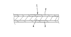
- FIG. 1 is a partial cross-sectional view showing an impact absorbing structure according to an embodiment of the present invention.
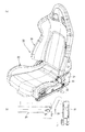
- FIG. 2 is a perspective view showing a seat structure for an automobile provided with a seat cushion portion and a seat back portion using the shock absorbing structure of the embodiment.
- FIG. 3 is a perspective view of the seat structure of FIG. 2 as viewed from the back.
- FIG. 4 is a cross-sectional view of the concavo-convex portion of the shell-type frame member employing the shock absorbing structure of the above embodiment.
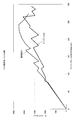
- 5 (a) to 5 (c) are graphs showing the results of the tensile stress of each test piece of Test Example 1
- FIG. 5 (d) is a graph showing the tensile stress of each test piece of Comparative Example 1. is there.
- FIGS. 5A to 6D are graphs showing only the average values of FIGS. 5A to 5D.
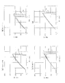
- FIG. 7 is a diagram showing the results of a tensile test in the roll direction of the biaxial woven fabric alone and the 4-axis woven fabric used in Test Example 1 and Test Example 2.
- FIG. 8 is a diagram showing the results of a tensile test in the bias direction of the biaxial woven fabric alone and the 4-axis woven fabric used in Test Example 1 and Test Example 2.
- FIG. 9 is a diagram showing the results of a tensile test in the width direction of the biaxial woven fabric alone and the 4-axis woven fabric used in Test Example 1 and Test Example 2.
- FIG. 7 is a diagram showing the results of a tensile test in the roll direction of the biaxial woven fabric alone and the 4-axis woven fabric used in Test Example 1 and Test Example 2.
- FIG. 8 is a diagram showing the results of a tensile test in the bias direction of the biaxial woven fabric alone
- FIG. 10 is a diagram illustrating a state in the vicinity of the left and right uneven portions of the shell-type frame member after the backward moment experiment is performed in Test Example 3.
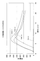
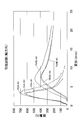
- FIG. 11 is a graph comparing the rear moment of the seat structure of Test Example 3 and the seat structure formed of the carbon shell.
- 12 (a) and 12 (b) show a side frame cover having a substantially L-shaped cross section manufactured by a laminate in which a biaxial woven fabric is sandwiched between two sheet members made of synthetic resin via an adhesive.
- FIG. 1 is a partial cross-sectional view showing an example of an impact absorbing structure 1 according to the present embodiment.
- the shock absorbing structure 1 of the present embodiment is composed of a laminated body in which a cloth-made planar member 4 is sandwiched between two synthetic resin-made planar members 2, 3. Has been. One planar member 2 and the cloth planar member 4, and the cloth planar member 4 and the other planar member 3 are joined to each other via an adhesive.
- the synthetic resin planar members 2 and 3 for example, those made of a thermosetting resin such as an unsaturated polyester resin can be used. Further, a fiber reinforced plastic in which glass fiber or the like is added to a thermosetting resin such as an unsaturated polyester resin can also be used.
- the cloth-made planar member 4 is preferably selected from a biaxial woven fabric, a triaxial woven fabric, a four-axial woven fabric, or a three-dimensional solid knitted fabric, and among these, it is more preferable to use a biaxial woven fabric. The point where the biaxial woven fabric is preferable will be described in detail in a test example described later.
- the three-dimensional solid knitted fabric is knitted by reciprocating a connecting yarn between a pair of ground knitted fabrics positioned at a predetermined interval, and is formed using a double raschel machine or the like. It is preferable to use the one in the range of 2 to 6 mm, and more preferably in the range of 2 to 4 mm.
- the impact-absorbing structure 1 is obtained by, for example, molding the planar members 2 and 3 made of synthetic resin in advance, one of the planar members 2, the fabric planar member 4, and the fabric planar member 4.
- the other planar member 3 can be manufactured by joining each via an adhesive. Moreover, it can also manufacture by sticking a fiber on both surfaces of the cloth-made planar member 4 via an adhesive and laminating a synthetic resin material on the fiber.
- an adhesive agent a synthetic rubber type adhesive agent and a thermosetting adhesive agent are used, for example.
- FIGS. 2 and 3 are views showing a vehicle seat structure 10 including a seat cushion portion 20 and a seat back portion 30.
- This is a bucket seat type seat structure
- the seat back portion 30 is formed by covering a shell type frame member 31 formed by curving a plate-like member with a skin material such as a three-dimensional knitted fabric.
- the configuration of the shock absorbing structure 1 shown in FIG. 1 is adopted as the shell type frame member 31.
- the shell-type frame member 31 of the present embodiment is composed of the planar members 2 and 3 made of synthetic resin, and the planar member 4 made of cloth made of a biaxial woven fabric sandwiched between both by an adhesive. Is done.
- the planar members 2 and 3 made of synthetic resin and a cloth-made frame member 31 are used.
- the laminate composed of the planar member 4 is preferably in the range of 1 to 4 mm in thickness.
- the shell frame member 31 is thin, as shown in FIGS. 2 and 3, as shown in FIG. 2 and FIG. Is preferred.
- the cloth-made planar member 4 is longer than the peripheral length L1, and the surplus portion (slack portion) 4a is generated. Is preferably laminated.
- Test Example 1 Polyethylene naphthalate (PEN) fiber made by Teijin Limited between fiber reinforced plastics based on unsaturated polyester resin for general lamination (made by Kyushu Paint Industry Co., Ltd., product name: “POLYKYUTO PC-420 TN”)
- PEN polyethylene naphthalate
- POLYKYUTO PC-420 TN unsaturated polyester resin for general lamination
- a laminate in which a biaxial woven fabric (length: 20 pieces / inch, width: 20 pieces / inch) formed from (1100 dtex) was sandwiched was produced.
- glass fiber which is a reinforcing material, is bonded to both sides of a biaxial woven fabric with a synthetic rubber adhesive (US, Airtech, spray synthetic rubber adhesive, trade name: AIRTAC 2).
- the above-mentioned general polyester unsaturated polyester resin was laminated and molded.
- a test piece was prepared from this laminate.
- the test pieces are those in which the direction along the winding direction (roll direction) of the biaxial fabric provided by the roll is the tensile direction, the diagonal direction (bias direction) is the tensile direction, and the width direction is tensile.
- Three pieces (n1, n2, n3) were prepared for each direction.
- the tensile stress and Izod impact strength were determined.
- the tensile stress was measured by a tensile test specified in JIS K7113.
- the test piece used in the tensile test was prepared according to JIS K7139 (cited standard ISO 527-2).
- the Izod impact strength was measured by an Izod impact test specified in JIS K7110.
- the test piece used in the Izod impact test was prepared in accordance with JIS K7139 (cited standard ISO 180).
- the tensile stress is as shown in Table 1.
- t is the thickness of each test piece (thickness as a laminate)
- Wc is the width of each test piece.
- Table 2 shows a laminated body in which planar members made of synthetic resin are laminated without using a biaxial woven fabric, specifically, glass fibers are joined together using the same adhesive as described above. It is the tensile stress of the laminated body (same kind laminated body (comparative example 1)) which laminated
- FIG. 5 is a graph showing the tensile stress in Table 2.
- the biaxial woven fabric is not interposed, and the cut out test piece has no directionality. Measurements were made on three cut specimens, and the average was obtained.
- FIG. 6 is a graph showing only the average values shown in FIG. Among these, FIGS. 6 (a) to 6 (c) also show the average values of the same type of laminated body of FIG. 6 (d).
- the tensile stress of the homogenous laminate of Comparative Example 1 is 75.9 MPa, whereas the laminate of Test Example 1 is the average of each test piece.
- the roll direction was 52.4 MPa
- the bias direction was 48.8 MPa
- the width direction was 57.4 MPa
- the reduction rates were 31.0%, 35.7%, and 24.4%, respectively.
- the fact that the tensile stress of a heterogeneous laminate laminated with an adhesive via a biaxial fabric is smaller than the tensile stress of the same type laminate means that between the biaxial fabric and each fiber reinforced plastic (glass fiber).
- the Izod impact strength was 46.9 kJ / m 2 for the homogenous laminate of Comparative Example 1, whereas the laminate of Test Example 1 was in the roll direction. : 33.7 kJ / m 2 , bias direction: 31.9 kJ / m 2 , width direction: 28.8 kJ / m 2 , and the decrease rates were 28.1%, 32.0%, and 38.6%, respectively. there were. Therefore, it can be seen that the laminate of Test Example 1 has a lower Izod impact strength than that of the same type of laminate of Comparative Example 1, and is useful for absorbing impact energy accordingly.
- Test Example 2 instead of the biaxial woven fabric of Test Example 1, a laminate (Test Example 2) in which a 4-axial woven fabric formed using aramid fibers (trademark “Technola” manufactured by Teijin Products Co., Ltd.) was manufactured. Also in Test Example 2, the direction along the winding direction (roll direction) of the roll of the 4-axis woven fabric becomes the tensile direction, the diagonal direction (bias direction) becomes the tensile direction, and the width direction becomes the tensile direction. Three pieces (n1, n2, n3) of each were prepared. For each specimen, the tensile stress and Izod impact strength were determined. In addition, the specification of the test piece and the method of each test are exactly the same as in the case of Test Example 1. Table 5 shows the results of the tensile stress obtained by the tensile test.
- the tensile stress of the same type laminate of Comparative Example 1 is 75.9 MPa (see Table 2), whereas from Table 5, the laminate of Test Example 1 is the average value of each test piece, in the roll direction: 70. 7 MPa, bias direction: 74.8 MPa, width direction: 62.8 MPa, and the reduction rates were 6.9%, 1.4%, and 17.3%, respectively.
- the tensile stress of the heterogeneous laminate obtained by laminating the 4-axis fabric using the adhesive is smaller than the tensile stress of the same-type laminate, and the 4-axis fabric and each fiber-reinforced plastic (glass fiber) It can be seen that delamination occurs between and the impact energy can be absorbed by the reduced tensile stress.
- the rate of decrease in tensile stress when compared with the same type laminate of Comparative Example 1 is biaxial.
- the woven fabric is larger, and it can be said that it is preferable to use a biaxial woven fabric in terms of absorption of impact energy.
- the tensile stress is lower than that of the same type of laminate in Comparative Example 1 in the case of the laminate of Test Example 2 in which a 4-axis fabric is interposed.
- the decrease rate of Test Example 1 is in the range of 24.4 to 35.7%, and the decrease rate of Test Example 2 is in the range of 1.4 to 17.3%.
- the reduction rate greatly exceeds 40%, it is considered that the strength is too low. Therefore, the reduction rate is 40% or less, preferably 20 to 40% including the range of the reduction rate of the biaxial woven fabric. Is desirable.
- the Izod impact strength of the laminate of Test Example 2 was as follows: roll direction: 44.1 kJ / m 2 , bias direction: 48.3 kJ / m 2 , lateral direction: 49.6 kJ / It was m 2.
- the roll direction was 6.0% lower than the Izod impact strength of the same laminate of Comparative Example 1: 46.9 kJ / m 2 (see Table 4), but the bias direction and the lateral direction were Comparative Example 1. It exceeded that of the same type of laminate.
- the laminate of Test Example 1 using the biaxial woven fabric having a value smaller than that of the same laminate of Comparative Example 1 is more reliably impacted by delamination. Absorption function can be demonstrated. In particular, human damage in the case of a rear collision can be reduced.
- the reduction rate of the Izod impact strength is too low to maintain the originally required strength. Therefore, the reduction rate is 40% or less, and preferably the reduction rate of the biaxial woven fabric (28.1 to 38.6%) and 20-40% are desirable.
- each test piece cut out in the roll direction, the bias direction, and the width direction is obtained for the biaxial woven fabric and the 4-axial woven fabric in the same manner as in Test Example 1.
- a tensile test was performed. The results are shown in FIGS. In FIGS. 7 to 9, “PEN” indicates a biaxial woven test piece, and “TNRB” indicates a 4-axial woven test piece.
- PEN indicates a biaxial woven test piece
- TNRB indicates a 4-axial woven test piece.
- Test Example 3 A shell-type frame member 31 was manufactured using a laminate (average thickness: 2.3 mm) having the same configuration as the test piece of Test Example 1. Then, the shell-type frame member 31 was employed in the seat back portion 30, and the seat structure 10 (see FIGS. 2 and 3) in which the seat back portion 30 was coupled to the seat cushion portion 20 via a reclining knuckle was manufactured.
- a rear moment experiment was conducted using this seat structure 10. This experiment is performed by applying a load to the seat back portion backward with a back pan simulating the shape of the back of a person in a state where the seat structure is assembled.
- FIG. 10 is a view showing a state in the vicinity of the left and right uneven portions 31a of the shell-type frame member 31 after the backward moment experiment.
- the synthetic resin on the surface was whitened, and the biaxial woven fabric was not torn and the surface layer and the lower layer were made of a synthetic resin planar member. I understand. Therefore, delamination occurs between the synthetic resin and the biaxial woven fabric, and the impact energy generated by the impact is absorbed by this delamination.
- FIG. 11 is a graph comparing the rear moments of the seat structure of Test Example 3 and the seat structure composed of the carbon shell.
- the seat structure of Test Example 3 has an increased absolute value of the rear moment and a reduced amount of frame deflection to the rear. .
- the difference between the two is the difference in energy absorption due to delamination.
- the phenomenon that the absolute value of the rear moment is increased, the impact load concentrated on the reclining knuckle is smaller than that of the seat structure made of carbon shell. This indicates that the difference between the two works as a force for delamination of each planar member of the laminate, and dissipates impact energy.
- Test Example 4 A side frame cover 21 having a substantially L-shaped cross section was produced from the same laminate as in Test Example 1. As shown in FIG. 12, the side frame cover 21 was connected to a substantially side-shaped metal side frame base 22 having a plate thickness of 1.2 mm. Then, a belt anchor 23 was attached to the side frame cover 21 so as to penetrate the side frame cover 21 in the thickness direction, and the base portion of the seat belt 24 was fixed to the belt anchor 23 with a bolt. In this state, a load was applied to the seat belt 24 so that the belt anchor 23 was pulled in a direction perpendicular to the axial direction (the direction of arrow A in FIG. 12).
- the side frame cover 21 was not cracked, and only a deformation such that the diameter of the through hole of the belt anchor 22 was increased. Therefore, it was found that the laminate obtained by sandwiching the biaxial woven fabric used in the above embodiment with the planar member made of synthetic resin can obtain high rigidity in addition to the impact absorbing action by the delamination action.
Landscapes
- Engineering & Computer Science (AREA)
- Textile Engineering (AREA)
- Aviation & Aerospace Engineering (AREA)
- Transportation (AREA)
- Mechanical Engineering (AREA)
- Laminated Bodies (AREA)
- Seats For Vehicles (AREA)
Abstract
座席構造のさらなる軽量化、薄型化を図る。
合成樹脂製の面状部材2,3間に布製の面状部材4をサンドイッチし、それらを接着剤を介して接合した積層体を、座席構造のシェル型フレーム部材に用いる。衝撃を受けた際には、積層体を構成する各層間で層間剥離が生じる。これにより、同種材質の面状部材同士を接合させてなる同種積層体と比較した場合に、引張応力及びアイゾット衝撃強さのいずれもが低下する。つまり、衝撃エネルギーを、積層体の面状部材同士を剥離させる力に転換して消費させ、それにより、該衝撃エネルギーを吸収する。シェル型フレーム部材そのもので衝撃を吸収できることになるため、該シェル型フレーム部材及びこれを用いた座席構造のさらなる軽量化、薄型化を図ることができる。
Description
本発明は、衝撃吸収構造体、該衝撃吸収構造体を少なくとも一部に用いたシェル型フレーム部材及び該シェル型フレーム部材を少なくとも一部に用いた座席構造に関する。
特許文献1~5には、座部フレームに、立体編物(三次元ネット材)などのクッション材を掛け渡して形成される座席構造が開示されている。このように、クッション材を座部フレームに掛け渡して形成する場合、底付き防止、振動吸収特性や衝撃吸収特性を上げるため、立体編物や二次元の布帛などのベースネットを、上記クッション材の下方に、弾性部材を介して設けている。特許文献1~5では、いずれも、トーションバーと、このトーションバーに連結され、該トーションバーを支点として回動可能に支持されるアームと、該アームに支持される支持フレームとを備えてなるトーションバーユニットを、座部の後部に配置し、ベースネットの後端を該支持フレームに連結することにより、ベースネットを弾性的に支持している。
特開2004-347577号公報
特開2003-182427号公報
特開2004-188164号公報
特開2004-141545号公報
WO2004/007238A1号公報
特許文献1~5に開示された技術によれば、立体編物、トーションバー等を用いることにより、ウレタン材を利用したものと比較して、軽量化、薄型化を図ることができる。また、立体編物及びトーションバー等のバネ系、ダンパ系が、振動吸収作用を担うと共に、衝撃吸収作用についてもこれらのバネ系、ダンパ系が主として機能する。その一方、座席構造のさらなる薄型化を図ろうとすると、座席構造の骨格系の剛性を上げていく必要がある。しかし、そうなると、車の後方衝突などによって発生する衝撃力を吸収するメカニズムが必要になる。衝撃力を吸収するメカニズムがないと、座席構造の中でのウイークポイントに力が集中する。このため、その部分の破壊を避けるための補強を行わなければならず、その結果として薄型化を図ったにも拘わらず重量アップにつながる。この重量アップを避けるには、薄型化された座席構造の中で衝撃力を吸収するクラッシャブルゾーンを設ける必要性がでてくる。また、立体編物を薄くしたり、トーションバーを廃止したりした場合にも、衝撃吸収作用をバネ系、ダンパ系以外に求める必要がある。
本発明は上記に鑑みなされたものであり、座席構造のフレーム部材として好適であり、座席構造のさらなる軽量化、薄型化に寄与できる衝撃吸収構造体を提供すること課題とする。また、かかる衝撃吸収構造体を用いたシェル型フレーム部材及び座席構造を提供することを課題とする。
本発明者らは上記課題を達成するため鋭意検討を重ねた結果、次のような知見を得た。すなわち、例えば、同種材質の面状部材同士を2枚接合させた同種積層体の引張り応力及びアイゾット衝撃強さは、面状部材1枚の引張応力及びアイゾット衝撃強さと比較すると通常2倍になるはずである。しかし、2枚の同種積層体に異種の面状部材を介在させた3層構造とすると、衝撃を受けた場合に層間剥離を生じ、積層体を構成する各面状部材の強度的なつながりが損なわれ、引張り応力及びアイゾット衝撃強さが共に、同種材質2枚を積層させてなる同種積層体よりも低下する、つまり、面状部材1枚の引張応力及びアイゾット衝撃強さの2倍未満になるという知見を得た。そこで、この低下した分に相当する力が各層間で層間剥離を起こさせる力として消費されるという前提に基づき、本発明を完成するに至った。
すなわち、本発明の衝撃吸収構造体は、少なくとも2層の異種材質の面状部材を積層させた積層体から構成される衝撃吸収構造体であって、前記積層体は、衝撃を受けた際に各層間で生じる層間剥離の作用により、前記積層体に用いられるいずれかの面状部材に同種材質の面状部材同士を積層させてなる同種積層体と比較した場合に、縦方向、横方向、斜め方向のうちの少なくとも一つの引張方向に関して引張応力及びアイゾット衝撃強さのいずれもが低下していると共に、その低下率が40%以下であることを特徴とする。
前記積層体は、少なくとも3層の面状部材からなり、そのうちの1層が他の層の面状部材と異なる材質からなるものであることが好ましい。前記低下率が、20%以上40%以下であることが好ましい。前記積層体は、前記同種積層体と比較した場合に、縦方向、横方向、斜め方向の全ての引張方向に関して引張強さ及びアイゾット衝撃強さのいずれもが低下していることが好ましい。前記積層体は、合成樹脂製の面状部材と布製の面状部材との積層体からなることが好ましい。前記積層体は、合成樹脂製の面状部材間に布製の面状部材がサンドイッチされてなることが好ましい。前記積層体を構成する面状部材同士が、接着剤を介して接合されていることが好ましい。前記布製の面状部材は、2軸織物、3軸織物、4軸織物又は三次元立体編物を用いることができ、前記布製の面状部材が、2軸織物であることがより好ましい。また、前記積層体には、凹凸部が形成されていることが好ましく、さらに、前記凹凸部に位置する前記布製の面状部材は、該凹凸部が形成されている範囲の周長よりも長い長さを有し、余肉部が生じた状態で積層されていることが好ましい。
本発明のシェル型フレーム部材は、衝撃吸収構造体を少なくとも一部に用いた、座席構造におけるシェル型フレーム部材であって、前記衝撃吸収構造体が、少なくとも2層の異種材質の面状部材を積層させた積層体から構成され、かつ、前記積層体が、衝撃を受けた際に各層間で生じる層間剥離の作用により、前記積層体に用いられるいずれかの面状部材に同種材質の面状部材同士を積層させてなる同種積層体と比較した場合に、縦方向、横方向、斜め方向のうちの少なくとも一つの引張方向に関して引張応力及びアイゾット衝撃強さのいずれもが低下していると共に、その低下率が40%以下であることを特徴とする。
本発明の座席構造は、衝撃吸収構造体がシェル型フレーム部材の少なくとも一部に用いられてなる座席構造であって、前記衝撃吸収構造体が、少なくとも2層の異種材質の面状部材を積層させた積層体から構成され、かつ、前記積層体が、衝撃を受けた際に各層間で生じる層間剥離の作用により、前記積層体に用いられるいずれかの面状部材に同種材質の面状部材同士を積層させてなる同種積層体と比較した場合に、縦方向、横方向、斜め方向のうちの少なくとも一つの引張方向に関して引張応力及びアイゾット衝撃強さのいずれもが低下していると共に、その低下率が40%以下であることを特徴とする。この座席構造は、輸送機器用シートであることが好ましい。
前記積層体は、少なくとも3層の面状部材からなり、そのうちの1層が他の層の面状部材と異なる材質からなるものであることが好ましい。前記低下率が、20%以上40%以下であることが好ましい。前記積層体は、前記同種積層体と比較した場合に、縦方向、横方向、斜め方向の全ての引張方向に関して引張強さ及びアイゾット衝撃強さのいずれもが低下していることが好ましい。前記積層体は、合成樹脂製の面状部材と布製の面状部材との積層体からなることが好ましい。前記積層体は、合成樹脂製の面状部材間に布製の面状部材がサンドイッチされてなることが好ましい。前記積層体を構成する面状部材同士が、接着剤を介して接合されていることが好ましい。前記布製の面状部材は、2軸織物、3軸織物、4軸織物又は三次元立体編物を用いることができ、前記布製の面状部材が、2軸織物であることがより好ましい。また、前記積層体には、凹凸部が形成されていることが好ましく、さらに、前記凹凸部に位置する前記布製の面状部材は、該凹凸部が形成されている範囲の周長よりも長い長さを有し、余肉部が生じた状態で積層されていることが好ましい。
本発明のシェル型フレーム部材は、衝撃吸収構造体を少なくとも一部に用いた、座席構造におけるシェル型フレーム部材であって、前記衝撃吸収構造体が、少なくとも2層の異種材質の面状部材を積層させた積層体から構成され、かつ、前記積層体が、衝撃を受けた際に各層間で生じる層間剥離の作用により、前記積層体に用いられるいずれかの面状部材に同種材質の面状部材同士を積層させてなる同種積層体と比較した場合に、縦方向、横方向、斜め方向のうちの少なくとも一つの引張方向に関して引張応力及びアイゾット衝撃強さのいずれもが低下していると共に、その低下率が40%以下であることを特徴とする。
本発明の座席構造は、衝撃吸収構造体がシェル型フレーム部材の少なくとも一部に用いられてなる座席構造であって、前記衝撃吸収構造体が、少なくとも2層の異種材質の面状部材を積層させた積層体から構成され、かつ、前記積層体が、衝撃を受けた際に各層間で生じる層間剥離の作用により、前記積層体に用いられるいずれかの面状部材に同種材質の面状部材同士を積層させてなる同種積層体と比較した場合に、縦方向、横方向、斜め方向のうちの少なくとも一つの引張方向に関して引張応力及びアイゾット衝撃強さのいずれもが低下していると共に、その低下率が40%以下であることを特徴とする。この座席構造は、輸送機器用シートであることが好ましい。
本発明の衝撃吸収構造体は、少なくとも2層の異種材質の面状部材を接合させた積層体から構成され、衝撃を受けた際に、積層体を構成する各層間で層間剥離を生じさせ、同種材質の面状部材同士を接合させてなる同種積層体と比較した場合に、引張応力及びアイゾット衝撃強さのいずれもが低下する構造である。つまり、衝撃エネルギーは、部品同士の連結部位、例えば、座席構造の場合には、リクライナを介してのつなぎ部位などにおいて局所的に集中しやすいが、本発明は、この衝撃エネルギーを、積層体の面状部材同士を剥離させる力としても消費させ、それにより、局所集中を緩和し、広い面で衝撃エネルギーの散逸を図るものである。従って、この衝撃吸収構造体を、シェル型フレーム部材として用いることにより、シェル型フレーム部材そのもので衝撃を吸収できることになるため、該シェル型フレーム部材及びこれを用いた座席構造のさらなる軽量化、薄型化を図ることができる。但し、層間剥離による衝撃エネルギーの散逸現象を起こさせる必要がある一方で、衝撃に伴う大きな荷重を受け止める部位も必要であるため、シェル型フレーム部材の中で、かかる層間剥離は部分的に生じる構造であることが好ましい。
なお、本発明は、2枚の同種積層体に異種の面状部材を介在させた3層構造の積層体とすると、層間剥離による衝撃エネルギーの散逸現象を生じさせやすいため好ましい。なかでも、合成樹脂製の面状部材間に布製の面状部材をサンドイッチした構成で、それらを接着剤を介して接合した構成とすることがより好ましい。また、積層体に、凹凸部を形成すると、衝撃を受けた際に、この凹凸部付近において層間剥離が生じやすくなるため、上記した荷重を受ける部位と層間剥離によるエネルギーを吸収する部位とを任意に設定しやすくなる。さらに、布製の面状部材として、該凹凸部が形成されている範囲の周長よりも長い長さのものを使用し、余肉部が生じた状態で積層すると、凹凸部付近における層間剥離をさらに生じさせやすくなるため好ましい。
1 衝撃吸収構造体
2,3 合成樹脂製の面状部材
4 布製の面状部材
10 座席構造
20 シートクッション部
21 サイドフレームカバー
30 シートバック部
31 シェル型フレーム部材
31a 凹凸部
2,3 合成樹脂製の面状部材
4 布製の面状部材
10 座席構造
20 シートクッション部
21 サイドフレームカバー
30 シートバック部
31 シェル型フレーム部材
31a 凹凸部
以下、図面に示した本発明の実施形態に基づき、さらに詳細に説明する。図1は、本実施形態に係る衝撃吸収構造体1の一例を示す一部断面図である。この図に示したように、本実施形態の衝撃吸収構造体1は、2枚の合成樹脂製の面状部材2,3間に、布製の面状部材4がサンドイッチされてなる積層体から構成されている。一方の面状部材2と布製の面状部材4、及び、布製の面状部材4と他方の面状部材3は、それぞれ接着剤を介して接合されている。
合成樹脂製の面状部材2,3は、例えば、不飽和ポリエステル樹脂等の熱硬化性樹脂からなるものを用いることができる。また、不飽和ポリエステル樹脂等の熱硬化性樹脂にガラス繊維等を入れた繊維強化プラスチックを用いることもできる。布製の面状部材4は、2軸織物、3軸織物、4軸織物又は三次元立体編物から選ばれることが好ましく、このうち、2軸織物を用いることがより好ましい。2軸織物が好ましい点については、後述の試験例で詳述する。なお、三次元立体編物は、所定間隔をおいて位置する一対のグランド編地間に連結糸を往復させて編成したもので、ダブルラッセル機等を用いて形成され、本実施形態の場合、厚さ2~6mmの範囲のものを用いることが好ましく、さらには、2~4mmの範囲のものを用いることがより好ましい。また、衝撃吸収構造体1は、例えば、合成樹脂製の面状部材2,3を予め成型しておき、一方の面状部材2と布製の面状部材4、及び、布製の面状部材4と他方の面状部材3は、それぞれ接着剤を介して接合することにより製造できる。また、布製の面状部材4の両面に、接着剤を介して繊維を貼着し、該繊維に対して合成樹脂材を積層して製造することもできる。なお、接着剤としては、例えば、合成ゴム系接着剤、熱硬化性接着剤が用いられる。
図2及び図3は、シートクッション部20とシートバック部30とを備えた自動車用の座席構造10を示した図である。これは、バケットシートタイプの座席構造であり、シートバック部30は、板状部材を湾曲させて形成したシェル型フレーム部材31に立体編物等の表皮材を被覆して形成されている。本実施形態では、このシェル型フレーム部材31として、図1に示した衝撃吸収構造体1の構成を採用している。すなわち、本実施形態のシェル型フレーム部材31は、合成樹脂製の面状部材2,3と、両者間に接着剤を介してサンドイッチされた2軸織物からなる布製の面状部材4とから構成される。なお、図2及び図3に示したような、座席構造10に用いられるシェル型フレーム部材31の場合には、所望の強度を得るために、合成樹脂製の面状部材2,3と布製の面状部材4からなる積層体は、厚さ1~4mmの範囲とすることが好ましい。
また、シェル型フレーム部材31は、薄型であるため、図2及び図3に示したように、適宜部位に凹凸部31aを形成し、断面係数を高めることによって、強度を確保する構成とすることが好ましい。また、図4に示したように、凹凸部31aを形成した範囲では、その周長L1よりも、布製の面状部材4の方が長く、余肉部(弛んだ部分)4aが生じた状態で積層されていることが好ましい。これにより、衝撃を受けて凹凸部31aがその厚み方向に押圧された場合、余肉部4aの部分が伸びようとするため、凹凸部31a付近において、布製の面状部材4が合成樹脂製の各面状部材2,3からより確実に剥離できる。
(試験例1)
一般積層用不飽和ポリエステル樹脂(九州塗料工業株式会社製、製品名:「POLYKYUTO PC-420 TN」)を母材とする繊維強化プラスチック間に、帝人(株)製のポリエチレンナフタレート(PEN)繊維(1100dtex)から形成した2軸織物(縦:20本/inch、横:20本/inch)をサンドイッチした積層体(試験例1)を製作した。具体的には、強化材であるガラス繊維を2軸織物の両面に、合成ゴム系接着剤(米国、Airtech社製、スプレー式合成ゴム系接着剤、商品名:AIRTAC 2)により接合し、これに、上記の一般積層用不飽和ポリエステル樹脂を積層して成型した。この積層体から試験片を準備した。試験片は、ロールで提供された2軸織物のロールの巻き取り方向(ロール方向)に沿った方向が引張り方向になるもの、斜め方向(バイアス方向)が引張り方向になるもの、幅方向が引張り方向となるものをそれぞれ3枚(n1,n2,n3)ずつ準備した。各試験片について、引張応力及びアイゾット衝撃強さを求めた。引張応力は、JIS K7113に規定された引張試験により測定した。引張試験で用いた試験片は、JIS K7139(引用規格ISO 527-2)に規定されたものを準備した。アイゾット衝撃強さは、JIS K7110に規定されたアイゾット衝撃試験により測定した。アイゾット衝撃試験で用いた試験片は、JIS K7139(引用規格ISO 180)に規定されたものを準備した。引張応力は、表1に示したとおりである。なお、表1中、tは各試験片の厚さ(積層体としての厚さ)、Wcは各試験片の幅である。また、表2は、2軸織物を介さずに、合成樹脂製の面状部材同士を積層した積層体、具体的には、ガラス繊維同士を上記と同じ接着剤を用いて接合し、一般積層用不飽和ポリエステル樹脂を積層して成型した積層体(同種積層体(比較例1))の引張応力である。
一般積層用不飽和ポリエステル樹脂(九州塗料工業株式会社製、製品名:「POLYKYUTO PC-420 TN」)を母材とする繊維強化プラスチック間に、帝人(株)製のポリエチレンナフタレート(PEN)繊維(1100dtex)から形成した2軸織物(縦:20本/inch、横:20本/inch)をサンドイッチした積層体(試験例1)を製作した。具体的には、強化材であるガラス繊維を2軸織物の両面に、合成ゴム系接着剤(米国、Airtech社製、スプレー式合成ゴム系接着剤、商品名:AIRTAC 2)により接合し、これに、上記の一般積層用不飽和ポリエステル樹脂を積層して成型した。この積層体から試験片を準備した。試験片は、ロールで提供された2軸織物のロールの巻き取り方向(ロール方向)に沿った方向が引張り方向になるもの、斜め方向(バイアス方向)が引張り方向になるもの、幅方向が引張り方向となるものをそれぞれ3枚(n1,n2,n3)ずつ準備した。各試験片について、引張応力及びアイゾット衝撃強さを求めた。引張応力は、JIS K7113に規定された引張試験により測定した。引張試験で用いた試験片は、JIS K7139(引用規格ISO 527-2)に規定されたものを準備した。アイゾット衝撃強さは、JIS K7110に規定されたアイゾット衝撃試験により測定した。アイゾット衝撃試験で用いた試験片は、JIS K7139(引用規格ISO 180)に規定されたものを準備した。引張応力は、表1に示したとおりである。なお、表1中、tは各試験片の厚さ(積層体としての厚さ)、Wcは各試験片の幅である。また、表2は、2軸織物を介さずに、合成樹脂製の面状部材同士を積層した積層体、具体的には、ガラス繊維同士を上記と同じ接着剤を用いて接合し、一般積層用不飽和ポリエステル樹脂を積層して成型した積層体(同種積層体(比較例1))の引張応力である。


図5の(a)~(c)は、表1の引張応力の結果をグラフ化したものであり、各方向とも、試験片3枚の平均の引張応力も求めている。図5(d)は、表2の引張応力をグラフ化したものである。なお、図5(d)の同種積層体の場合には、2軸織物を介しておらず、切り出した試験片に方向性はないため、切り出し方向は考慮せずに、上記と同じ大きさに切り出した3枚の試験片について測定し、その平均を求めている。
図6は、上記図5の各平均値のみを取り出して示したグラフである。このうち、図6(a)~(c)は、図6(d)の同種積層体の平均値を併せて表示している。
上記の結果、まず、表1及び表2から、ロール方向では、比較例1の同種積層体の引張応力が75.9MPaであるのに対し、試験例1の積層体は、各試験片の平均値で、ロール方向:52.4MPa、バイアス方向:48.8MPa、幅方向:57.4MPaであり、低下率は、それぞれ、31.0%、35.7%、24.4%であった。2軸織物を介して接着剤を用いて積層した異種積層体の引張応力が、同種積層体の引張応力よりも小さくなるということは、2軸織物と各繊維強化プラスチック(ガラス繊維)との間で層間剥離が生じたことを示すものであり、この低下した引張応力分が衝撃エネルギーの吸収分となる。図6から同種積層体と比較したときの試験例1の各試験片のエネルギー吸収量を求めると、図6(a)のロール方向は1220N・mm、図6(b)のバイアス方向は18433N・mm、図6(c)の幅方向は9257.9N・mmであった。
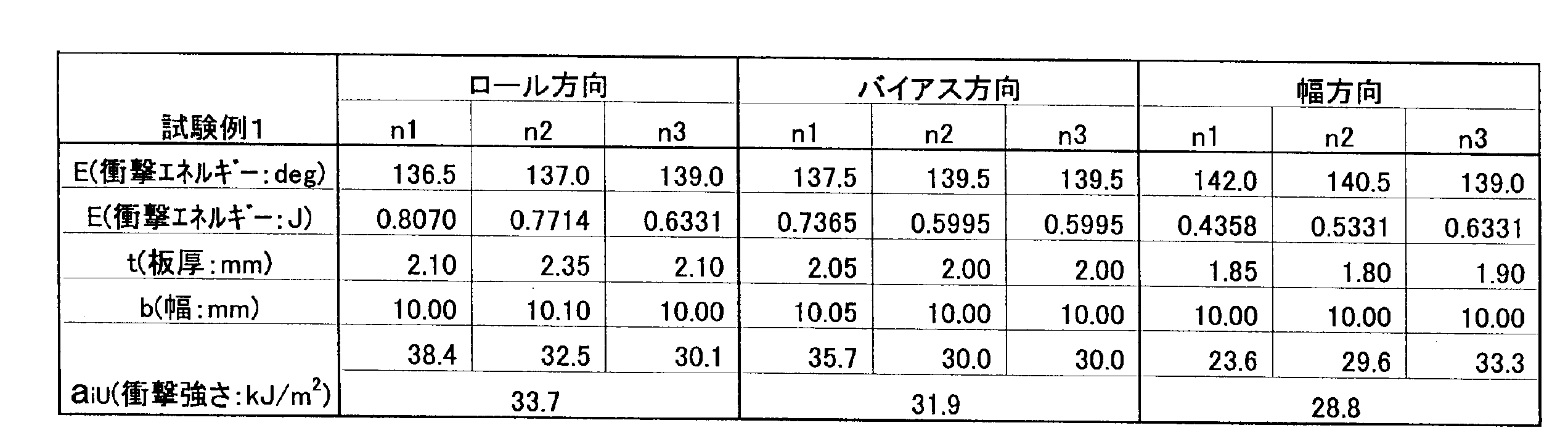
一方、アイゾット衝撃強さは、表3及び表4に示したように、比較例1の同種積層体が46.9kJ/m2であったのに対し、試験例1の積層体は、ロール方向:33.7kJ/m2、バイアス方向:31.9kJ/m2、幅方向:28.8kJ/m2であり、低下率は、それぞれ28.1%、32.0%、38.6%であった。従って、試験例1の積層体は、比較例1の同種積層体よりもアイゾット衝撃強さも低下しており、その分、衝撃エネルギーの吸収に役立つことがわかる。

(試験例2)
試験例1の2軸織物に代えて、アラミド繊維(帝人プロダクツ(株)製、商標「テクノーラ」)を用いて形成した4軸織物をサンドイッチした積層体(試験例2)を製作した。試験例2においても、4軸織物のロールの巻き取り方向(ロール方向)に沿った方向が引張り方向になるもの、斜め方向(バイアス方向)が引張り方向になるもの、幅方向が引張り方向になるものをそれぞれ3枚(n1,n2,n3)ずつ準備した。各試験片について、引張応力及びアイゾット衝撃強さを求めた。なお、試験片の規格及び各試験の方法は試験例1の場合と全く同じである。表5が、引張試験により求めた引張応力の結果である。
試験例1の2軸織物に代えて、アラミド繊維(帝人プロダクツ(株)製、商標「テクノーラ」)を用いて形成した4軸織物をサンドイッチした積層体(試験例2)を製作した。試験例2においても、4軸織物のロールの巻き取り方向(ロール方向)に沿った方向が引張り方向になるもの、斜め方向(バイアス方向)が引張り方向になるもの、幅方向が引張り方向になるものをそれぞれ3枚(n1,n2,n3)ずつ準備した。各試験片について、引張応力及びアイゾット衝撃強さを求めた。なお、試験片の規格及び各試験の方法は試験例1の場合と全く同じである。表5が、引張試験により求めた引張応力の結果である。
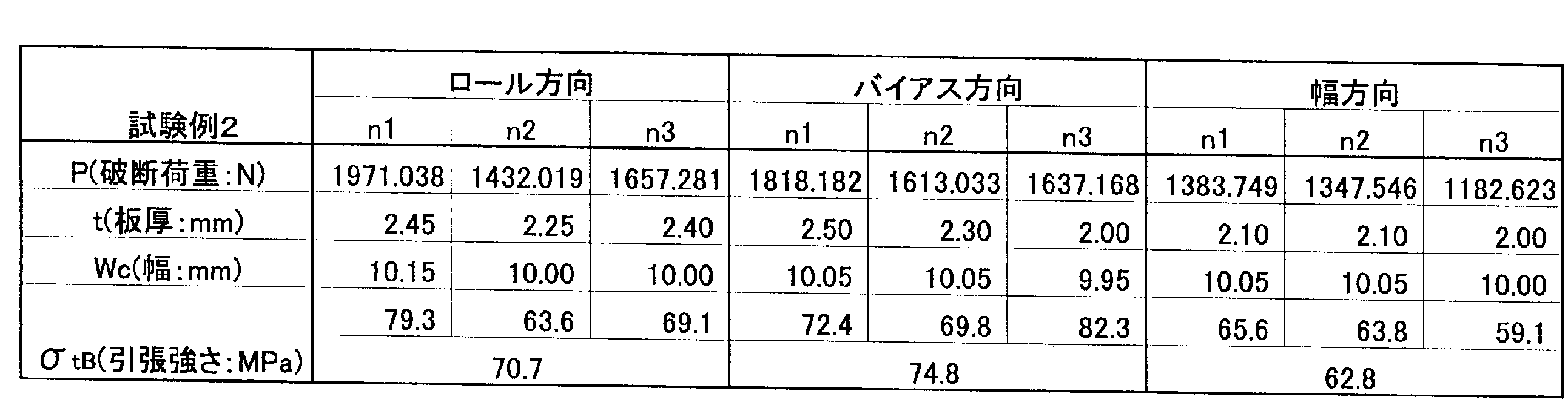
比較例1の同種積層体の引張応力が75.9MPa(表2参照)であるのに対し、表5から、試験例1の積層体は、各試験片の平均値で、ロール方向:70.7MPa、バイアス方向:74.8MPa、幅方向:62.8MPaであり、低下率は、それぞれ、6.9%、1.4%、17.3%であった。試験例2においても、4軸織物を接着剤を用いて積層した異種積層体の引張応力は、同種積層体の引張応力よりも小さくなっており、4軸織物と各繊維強化プラスチック(ガラス繊維)との間で層間剥離が生じ、低下した引張応力分、衝撃エネルギーを吸収できることがわかる。
しかしながら、試験例1の2軸織物を介在させた場合と試験例2の4軸織物を介在させた場合とでは、比較例1の同種積層体と比べた時の引張応力の低下率は2軸織物の方が大きく、衝撃エネルギーの吸収の点では2軸織物を用いた方が好ましいと言える。
但し、2軸織物を介在させた試験例1の積層体、4軸織物を介在させた試験例2の積層体のいずれの場合も、比較例1の同種積層体よりも引張応力が低下しており、試験例1の低下率は、24.4~35.7%の範囲、試験例2の低下率は、1.4~17.3%の範囲である。低下率が40%を大きく超えるような場合には、強度的に低すぎると考えられるため、低下率は40%以下、好ましくは2軸織物の低下率の範囲を含む20~40%となるものが望ましい。
一方、試験例2の積層体のアイゾット衝撃強さは、表6に示したように、ロール方向:44.1kJ/m2、バイアス方向:48.3kJ/m2、横方向:49.6kJ/m2であった。ロール方向については、比較例1の同種積層体のアイゾット衝撃強さ:46.9kJ/m2(表4参照)よりも6.0%低下していたが、バイアス方向及び横方向は比較例1の同種積層体を上回るものであった。このことから、引張応力、アイゾット衝撃強さのいずれの試験においても、比較例1の同種積層体より値が小さくなる2軸織物を用いた試験例1の積層体がより確実に層間剥離による衝撃吸収機能を発揮できる。特に、後方衝突事故の場合の人のダメージを軽減できる。なお、アイゾット衝撃強さの低下率も、低すぎては本来必要な強度を維持できない可能性があるため、低下率40%以下であって、好ましくは2軸織物の低下率(28.1~38.6%)を含む20~40%となるものが望ましい。

ここで、2軸織物と4軸織物との違いを調べるため、2軸織物単体及び4軸織物単体について、試験例1と同様に、ロール方向、バイアス方向、幅方向に切り出した各試験片について引張試験を行った。結果を図7~図9に示す。なお、図7~図9において「PEN」の付いた表示は2軸織物の試験片を示し、「TNRB」の付いた表示は4軸織物の試験片を示す。まず、2軸織物について比較すると、ロール方向と幅方向の引張応力に比べ、バイアス方向の引張応力が極めて低い。これに対し、4軸織物の場合には、バイアス方向の引張応力が最も高く、ロール方向と幅方向の引張応力が小さくなっている。
これらのことから、2軸織物及び4軸織物とも、引張方向によって、応力に差が存在することがわかる。従って、衝撃が加わった際には、各織物の繊維は、応力の弱い方に向かってねじれるようになり、このねじれが合成樹脂製の面状部材から剥がれようとする力として作用する。そして、2軸織物と4軸織物とを比較した場合には、引張方向による応力の差は、2軸織物の方が著しく大きい。従って、2軸織物は衝撃を受けた際のねじれが4軸織物より大きく、この点からも、2軸織物の方が層間剥離を生じやすいことがわかる。
(試験例3)
試験例1の試験片と同じ構成の積層体(平均厚さ:2.3mm)を用いたシェル型フレーム部材31を製作した。そして、該シェル型フレーム部材31をシートバック部30に採用し、このシートバック部30をリクライニングナックルを介してシートクッション部20と結合した座席構造10(図2及び図3参照)を製作した。
試験例1の試験片と同じ構成の積層体(平均厚さ:2.3mm)を用いたシェル型フレーム部材31を製作した。そして、該シェル型フレーム部材31をシートバック部30に採用し、このシートバック部30をリクライニングナックルを介してシートクッション部20と結合した座席構造10(図2及び図3参照)を製作した。
この座席構造10を用いて後方モーメント実験を行った。本実験は、座席構造に組み立てた状態で、人の背部形状を模擬したバックパンにより、シートバック部に後方へ荷重をかけて行う。
図10は、後方モーメント実験後のシェル型フレーム部材31の左右の凹凸部31a付近の様子を示す図である。この図に示したように、凹凸部31a付近において、表面の合成樹脂に白化が生じ、2軸織物が裂けずに表層、下層の合成樹脂製の面状部材との間で剥離が生じたことがわかる。従って、合成樹脂と2軸織物との間に層間剥離が生じ、この剥離により、衝撃によって生じる衝撃エネルギーが吸収される。
また、試験例3の座席構造(本発明のシェル型フレーム部材31を用いた座席構造)で採用したものと同じリクライニングナックルを使用してシートバック部とシートクッション部とを連結したカーボンシェルを用いた座席構造に、試験例3と同様の後方モーメント実験を行った。試験例3の座席構造及びカーボンシェルからなる座席構造の後方モーメントを比較したグラフが図11である。
図11から、リクライニングナックルが同一の強度を有するにも拘わらず、試験例3の座席構造の方が、後方モーメントの絶対値が上昇し、かつ、後方へのフレームのたわみ量も減少していた。両者の差が、層間剥離によるエネルギー吸収量の差である。換言すると、試験例3の座席構造の方が後方モーメントの絶対値が上昇している等の現象は、カーボンシェルからなる座席構造と比較して、リクライニングナックルに集中する衝撃荷重が小さくなっているということを示すものであり、両者の差分が、積層体の各面状部材を層間剥離させる力として働き、衝撃エネルギーを散逸させている。
(試験例4)
試験例1と同じ積層体により、断面略L字状のサイドフレームカバー21を製作した。このサイドフレームカバー21を図12に示したように、略コ字状の板厚1.2mmの金属製のサイドフレーム基体22に向かい合わせて連結した。そして、サイドフレームカバー21に、該サイドフレームカバー21の厚み方向に貫通するようにベルトアンカー23を取り付け、このベルトアンカー23にシートベルト24の基部をボルトを介して固定した。かかる状態で、ベルトアンカー23がその軸方向と直交する方向(図12の矢印A方向)に引っ張っられるようにシートベルト24に負荷をかけた。
試験例1と同じ積層体により、断面略L字状のサイドフレームカバー21を製作した。このサイドフレームカバー21を図12に示したように、略コ字状の板厚1.2mmの金属製のサイドフレーム基体22に向かい合わせて連結した。そして、サイドフレームカバー21に、該サイドフレームカバー21の厚み方向に貫通するようにベルトアンカー23を取り付け、このベルトアンカー23にシートベルト24の基部をボルトを介して固定した。かかる状態で、ベルトアンカー23がその軸方向と直交する方向(図12の矢印A方向)に引っ張っられるようにシートベルト24に負荷をかけた。
その結果、サイドフレームカバー21には割れが生じず、ベルトアンカー22の貫通穴が拡径するような変形が生じただけであった。従って、上記実施形態で用いた2軸織物を合成樹脂製の面状部材でサンドイッチした積層体は、層間剥離作用による衝撃吸収作用に加えて、高い剛性が得られることがわかった。
Claims (14)
- 少なくとも2層の異種材質の面状部材を積層させた積層体から構成される衝撃吸収構造体であって、
前記積層体は、衝撃を受けた際に各層間で生じる層間剥離の作用により、前記積層体に用いられるいずれかの面状部材に同種材質の面状部材同士を積層させてなる同種積層体と比較した場合に、縦方向、横方向、斜め方向のうちの少なくとも一つの引張方向に関して引張応力及びアイゾット衝撃強さのいずれもが低下していると共に、その低下率が40%以下であることを特徴とする衝撃吸収構造体。 - 前記積層体は、少なくとも3層の面状部材からなり、そのうちの1層が他の層の面状部材と異なる材質からなるものであることを特徴とする請求1記載の衝撃吸収構造体。
- 前記低下率が、20%以上40%以下であることを特徴とする請求項1記載の衝撃吸収構造体。
- 前記積層体は、前記同種積層体と比較した場合に、縦方向、横方向、斜め方向の全ての引張方向に関して引張強さ及びアイゾット衝撃強さのいずれもが低下していることを特徴とする請求項1記載の衝撃吸収構造体。
- 前記積層体が、合成樹脂製の面状部材と布製の面状部材との積層体からなることを特徴とする請求項1記載の衝撃吸収構造体。
- 前記積層体が、合成樹脂製の面状部材間に布製の面状部材がサンドイッチされてなることを特徴とする請求項5記載の衝撃吸収構造体。
- 前記積層体を構成する面状部材同士が、接着剤を介して接合されていることを特徴とする請求項1記載の衝撃吸収構造体。
- 前記布製の面状部材が、2軸織物、3軸織物、4軸織物又は三次元立体編物であることを特徴とする請求項5記載の衝撃吸収構造体。
- 前記布製の面状部材が、2軸織物であることを特徴とする請求項8記載の衝撃吸収構造体。
- 前記積層体には、凹凸部が形成されていることを特徴とする請求項1記載の衝撃吸収構造体。
- 前記凹凸部に位置する前記布製の面状部材は、該凹凸部が形成されている範囲の周長よりも長い長さを有し、余肉部が生じた状態で積層されていることを特徴とする請求項10記載の衝撃吸収構造体。
- 衝撃吸収構造体を少なくとも一部に用いた、座席構造におけるシェル型フレーム部材であって、
前記衝撃吸収構造体が、少なくとも2層の異種材質の面状部材を積層させた積層体から構成され、かつ、前記積層体が、衝撃を受けた際に各層間で生じる層間剥離の作用により、前記積層体に用いられるいずれかの面状部材に同種材質の面状部材同士を積層させてなる同種積層体と比較した場合に、縦方向、横方向、斜め方向のうちの少なくとも一つの引張方向に関して引張応力及びアイゾット衝撃強さのいずれもが低下していると共に、その低下率が40%以下であることを特徴とするシェル型フレーム部材。 - 衝撃吸収構造体がシェル型フレーム部材の少なくとも一部に用いられてなる座席構造であって、
前記衝撃吸収構造体が、少なくとも2層の異種材質の面状部材を積層させた積層体から構成され、かつ、前記積層体が、衝撃を受けた際に各層間で生じる層間剥離の作用により、前記積層体に用いられるいずれかの面状部材に同種材質の面状部材同士を積層させてなる同種積層体と比較した場合に、縦方向、横方向、斜め方向のうちの少なくとも一つの引張方向に関して引張応力及びアイゾット衝撃強さのいずれもが低下していると共に、その低下率が40%以下であることを特徴とする座席構造。 - 輸送機器用シートであることを特徴とする請求項13記載の座席構造。
Priority Applications (2)
| Application Number | Priority Date | Filing Date | Title |
|---|---|---|---|
| US12/810,556 US8376456B2 (en) | 2007-12-27 | 2008-12-22 | Impact absorbing structural body, shell type frame member and seat structure |
| EP20080867369 EP2236352B1 (en) | 2007-12-27 | 2008-12-22 | Impact absorbing structure, shell type frame member, and seat structure |
Applications Claiming Priority (2)
| Application Number | Priority Date | Filing Date | Title |
|---|---|---|---|
| JP2007338226A JP5255831B2 (ja) | 2007-12-27 | 2007-12-27 | 衝撃吸収構造体、シェル型フレーム部材及び座席構造 |
| JP2007-338226 | 2007-12-27 |
Publications (1)
| Publication Number | Publication Date |
|---|---|
| WO2009084505A1 true WO2009084505A1 (ja) | 2009-07-09 |
Family
ID=40824219
Family Applications (1)
| Application Number | Title | Priority Date | Filing Date |
|---|---|---|---|
| PCT/JP2008/073320 Ceased WO2009084505A1 (ja) | 2007-12-27 | 2008-12-22 | 衝撃吸収構造体、シェル型フレーム部材及び座席構造 |
Country Status (4)
| Country | Link |
|---|---|
| US (1) | US8376456B2 (ja) |
| EP (1) | EP2236352B1 (ja) |
| JP (1) | JP5255831B2 (ja) |
| WO (1) | WO2009084505A1 (ja) |
Families Citing this family (15)
| Publication number | Priority date | Publication date | Assignee | Title |
|---|---|---|---|---|
| US8733834B2 (en) * | 2011-04-29 | 2014-05-27 | Lear Corporation | Trim assembly |
| AU2012267260B2 (en) * | 2011-06-07 | 2017-03-30 | Innova Helicopters Technology Holdings Nz Limited | A helicopter |
| IN2014DN08535A (ja) | 2012-05-07 | 2015-05-15 | Johnson Controls Tech Co | |
| DE102012013208B4 (de) | 2012-05-07 | 2019-07-25 | Adient Luxembourg Holding S.À R.L. | Sitzteil eines Fahrzeugsitzes |
| US9580175B2 (en) * | 2013-04-04 | 2017-02-28 | Franklin Products, Inc. | Aircraft seat back assembly |
| GB2515576A (en) * | 2013-06-28 | 2014-12-31 | Gordon Murray Design Ltd | Vehicle Seat |
| JP2015098299A (ja) * | 2013-11-20 | 2015-05-28 | トヨタ紡織株式会社 | 乗物用シート |
| DE102013224927A1 (de) * | 2013-12-04 | 2015-06-11 | Bayerische Motoren Werke Aktiengesellschaft | Tragendes, flächiges Formteil aus einem Mehrschichtfaserverbundwerkstoff, insbesondere für eine Fahrzeugkarosserie |
| KR101560092B1 (ko) * | 2014-05-19 | 2015-10-13 | 김수열 | 충격 강도 향상을 위한 이중 구조의 합성수지재 곡물 포장지 |
| FR3024432B1 (fr) * | 2014-08-01 | 2018-02-02 | Epsilon Composite | Tube de structure de type hybride, notamment pour siege aeronautique |
| JP6527418B2 (ja) * | 2015-07-31 | 2019-06-05 | トヨタ紡織株式会社 | 乗物用シート |
| JP6783621B2 (ja) * | 2016-10-26 | 2020-11-11 | 株式会社タチエス | 車両用シート |
| JP6994840B2 (ja) | 2017-04-03 | 2022-01-14 | 株式会社ジャムコ | 背面シェル構造体及び座席ユニット |
| US10308203B2 (en) * | 2017-06-20 | 2019-06-04 | Ford Global Technologies, Llc | Stab proof back panel for law enforcement vehicle |
| US10494062B2 (en) | 2017-11-10 | 2019-12-03 | Robert Kohen | Marine seat with safety rollback |
Citations (11)
| Publication number | Priority date | Publication date | Assignee | Title |
|---|---|---|---|---|
| JPH0687185A (ja) * | 1992-07-22 | 1994-03-29 | Mitsui Toatsu Chem Inc | 積層成形品 |
| JP2000281803A (ja) * | 1999-04-01 | 2000-10-10 | Sekisui Chem Co Ltd | 損傷修復複合材及びその製造方法並びに修復方法 |
| JP2003182427A (ja) | 2001-12-20 | 2003-07-03 | Delta Tooling Co Ltd | 衝撃吸収構造及び座席構造 |
| JP2004001729A (ja) * | 2002-04-26 | 2004-01-08 | Toyota Central Res & Dev Lab Inc | 車両用シート |
| WO2004007238A1 (ja) | 2002-07-17 | 2004-01-22 | Delta Tooling Co., Ltd. | 座席構造 |
| JP2004141545A (ja) | 2002-10-28 | 2004-05-20 | Delta Tooling Co Ltd | 座席構造 |
| JP2004188164A (ja) | 2002-03-27 | 2004-07-08 | Delta Tooling Co Ltd | 座席構造 |
| JP2004347577A (ja) | 2003-05-21 | 2004-12-09 | Delta Tooling Co Ltd | 座席構造及び荷重検出装置 |
| JP2006077815A (ja) * | 2004-09-07 | 2006-03-23 | Nissan Motor Co Ltd | エネルギ吸収部材及びそれを用いた自動車用フード |
| JP2007283758A (ja) * | 2006-03-24 | 2007-11-01 | Du Pont Toray Co Ltd | 高機能コンポジット |
| JP2007313907A (ja) * | 2004-08-23 | 2007-12-06 | Delta Tooling Co Ltd | シートフレーム、シート構造及びシートフレームの製造方法 |
Family Cites Families (15)
| Publication number | Priority date | Publication date | Assignee | Title |
|---|---|---|---|---|
| JPS55150348A (en) * | 1979-05-11 | 1980-11-22 | Mitsui Petrochemical Ind | Seat |
| DE3049425C2 (de) * | 1980-12-30 | 1991-09-05 | Messerschmitt-Bölkow-Blohm GmbH, 8000 München | Aufprall-Schutz-Bauteil |
| US5514448A (en) | 1992-07-22 | 1996-05-07 | Mitsui Toatsu Chemicals, Inc. | Laminated molding |
| ATA20593A (de) * | 1993-02-05 | 1998-08-15 | Greiner & Soehne C A | Fahrzeugsitz, insbesondere für flugzeuge |
| US6739673B2 (en) * | 2001-08-15 | 2004-05-25 | Dow Global Technologies, Inc. | Seating system |
| US6854805B2 (en) | 2002-03-27 | 2005-02-15 | Delta Tooling Co., Ltd. | Seat structure |
| US6896324B1 (en) * | 2002-04-19 | 2005-05-24 | Adam Aircraft Industries | Hybrid composite-metal energy absorbing seat |
| US7134718B2 (en) | 2002-04-26 | 2006-11-14 | Kabushiki Kaisha Toyota Chuo Kenkyusho | Vehicle seat |
| US7128373B2 (en) * | 2002-09-27 | 2006-10-31 | Dow Global Technologies, Inc. | Seating system and method of forming same |
| US7070242B2 (en) * | 2002-10-02 | 2006-07-04 | Simula, Inc. | Armor system with monolithic ceramic shell |
| US7111888B1 (en) * | 2003-09-09 | 2006-09-26 | Motorsports Builders, Llc | Molded safety seat |
| FR2869565B1 (fr) * | 2004-04-28 | 2007-08-10 | Eurocopter France | Protection d'une structure composite aux impacts |
| US7717519B2 (en) * | 2006-12-22 | 2010-05-18 | The Boeing Company | Composite seat back structure for a lightweight aircraft seat assembly |
| US7716797B2 (en) * | 2006-12-22 | 2010-05-18 | The Boeing Company | Composite seat pan structure for a lightweight aircraft seat assembly |
| JP5470598B2 (ja) * | 2008-03-03 | 2014-04-16 | 株式会社デルタツーリング | 構造材及び輸送機器用座席構造 |
-
2007
- 2007-12-27 JP JP2007338226A patent/JP5255831B2/ja not_active Expired - Fee Related
-
2008
- 2008-12-22 WO PCT/JP2008/073320 patent/WO2009084505A1/ja not_active Ceased
- 2008-12-22 US US12/810,556 patent/US8376456B2/en not_active Expired - Fee Related
- 2008-12-22 EP EP20080867369 patent/EP2236352B1/en not_active Not-in-force
Patent Citations (11)
| Publication number | Priority date | Publication date | Assignee | Title |
|---|---|---|---|---|
| JPH0687185A (ja) * | 1992-07-22 | 1994-03-29 | Mitsui Toatsu Chem Inc | 積層成形品 |
| JP2000281803A (ja) * | 1999-04-01 | 2000-10-10 | Sekisui Chem Co Ltd | 損傷修復複合材及びその製造方法並びに修復方法 |
| JP2003182427A (ja) | 2001-12-20 | 2003-07-03 | Delta Tooling Co Ltd | 衝撃吸収構造及び座席構造 |
| JP2004188164A (ja) | 2002-03-27 | 2004-07-08 | Delta Tooling Co Ltd | 座席構造 |
| JP2004001729A (ja) * | 2002-04-26 | 2004-01-08 | Toyota Central Res & Dev Lab Inc | 車両用シート |
| WO2004007238A1 (ja) | 2002-07-17 | 2004-01-22 | Delta Tooling Co., Ltd. | 座席構造 |
| JP2004141545A (ja) | 2002-10-28 | 2004-05-20 | Delta Tooling Co Ltd | 座席構造 |
| JP2004347577A (ja) | 2003-05-21 | 2004-12-09 | Delta Tooling Co Ltd | 座席構造及び荷重検出装置 |
| JP2007313907A (ja) * | 2004-08-23 | 2007-12-06 | Delta Tooling Co Ltd | シートフレーム、シート構造及びシートフレームの製造方法 |
| JP2006077815A (ja) * | 2004-09-07 | 2006-03-23 | Nissan Motor Co Ltd | エネルギ吸収部材及びそれを用いた自動車用フード |
| JP2007283758A (ja) * | 2006-03-24 | 2007-11-01 | Du Pont Toray Co Ltd | 高機能コンポジット |
Non-Patent Citations (1)
| Title |
|---|
| See also references of EP2236352A4 * |
Also Published As
| Publication number | Publication date |
|---|---|
| EP2236352A1 (en) | 2010-10-06 |
| EP2236352B1 (en) | 2015-04-15 |
| JP2009154821A (ja) | 2009-07-16 |
| EP2236352A4 (en) | 2012-12-26 |
| JP5255831B2 (ja) | 2013-08-07 |
| US8376456B2 (en) | 2013-02-19 |
| US20110278901A1 (en) | 2011-11-17 |
Similar Documents
| Publication | Publication Date | Title |
|---|---|---|
| JP5255831B2 (ja) | 衝撃吸収構造体、シェル型フレーム部材及び座席構造 | |
| JP5470598B2 (ja) | 構造材及び輸送機器用座席構造 | |
| US8528982B2 (en) | Seat | |
| GB2477234A (en) | Aircraft seat leg fabrication method | |
| WO2004007238A1 (ja) | 座席構造 | |
| WO2011018930A1 (ja) | 乗物用シート | |
| JP4483409B2 (ja) | シート | |
| JP6358280B2 (ja) | 車体パネルの取付構造 | |
| JP5952990B2 (ja) | 金属樹脂複合体 | |
| JP6235384B2 (ja) | 自動車の車体構造 | |
| JP5669288B2 (ja) | シェル型フレーム部材及び座席構造 | |
| JP5771020B2 (ja) | 車両用シートバックフレーム構造 | |
| CN105793107B (zh) | 座椅框架 | |
| JP2006200702A (ja) | 衝撃吸収部材 | |
| JP6686700B2 (ja) | 繊維強化樹脂部品のフランジ製造方法及び繊維強化樹脂部品のフランジ構造 | |
| JP7537333B2 (ja) | 複合部材、自動車用シート、自動車用部品 | |
| JP2021059043A (ja) | 芯材及び複合部材 | |
| JP2025018197A (ja) | 車体ピラー構造 | |
| WO2018174037A1 (ja) | 傾斜車両 | |
| JP2015098282A (ja) | シートフレーム | |
| KR20120140352A (ko) | 컴포트가 향상된 복판형 시트 백 프레임 | |
| TW201838860A (zh) | 傾斜車輛 | |
| JP2004051030A (ja) | Frp製自動車ルーフ | |
| JP2017165255A (ja) | 車両用シート |
Legal Events
| Date | Code | Title | Description |
|---|---|---|---|
| 121 | Ep: the epo has been informed by wipo that ep was designated in this application |
Ref document number: 08867369 Country of ref document: EP Kind code of ref document: A1 |
|
| NENP | Non-entry into the national phase |
Ref country code: DE |
|
| WWE | Wipo information: entry into national phase |
Ref document number: 2008867369 Country of ref document: EP |
|
| WWE | Wipo information: entry into national phase |
Ref document number: 12810556 Country of ref document: US |