WO2009084505A1 - Structure d'absorption d'impact, élément de cadre de type coque et structure de siège - Google Patents
Structure d'absorption d'impact, élément de cadre de type coque et structure de siège Download PDFInfo
- Publication number
- WO2009084505A1 WO2009084505A1 PCT/JP2008/073320 JP2008073320W WO2009084505A1 WO 2009084505 A1 WO2009084505 A1 WO 2009084505A1 JP 2008073320 W JP2008073320 W JP 2008073320W WO 2009084505 A1 WO2009084505 A1 WO 2009084505A1
- Authority
- WO
- WIPO (PCT)
- Prior art keywords
- laminate
- impact
- absorbing structure
- planar members
- planar
- Prior art date
- Legal status (The legal status is an assumption and is not a legal conclusion. Google has not performed a legal analysis and makes no representation as to the accuracy of the status listed.)
- Ceased
Links
Images





Classifications
-
- B—PERFORMING OPERATIONS; TRANSPORTING
- B60—VEHICLES IN GENERAL
- B60N—SEATS SPECIALLY ADAPTED FOR VEHICLES; VEHICLE PASSENGER ACCOMMODATION NOT OTHERWISE PROVIDED FOR
- B60N2/00—Seats specially adapted for vehicles; Arrangement or mounting of seats in vehicles
- B60N2/24—Seats specially adapted for vehicles; Arrangement or mounting of seats in vehicles for particular purposes or particular vehicles
- B60N2/42—Seats specially adapted for vehicles; Arrangement or mounting of seats in vehicles for particular purposes or particular vehicles the seat constructed to protect the occupant from the effect of abnormal g-forces, e.g. crash or safety seats
- B60N2/4249—Seats specially adapted for vehicles; Arrangement or mounting of seats in vehicles for particular purposes or particular vehicles the seat constructed to protect the occupant from the effect of abnormal g-forces, e.g. crash or safety seats fixed structures, i.e. where neither the seat nor a part thereof are displaced during a crash
-
- B—PERFORMING OPERATIONS; TRANSPORTING
- B32—LAYERED PRODUCTS
- B32B—LAYERED PRODUCTS, i.e. PRODUCTS BUILT-UP OF STRATA OF FLAT OR NON-FLAT, e.g. CELLULAR OR HONEYCOMB, FORM
- B32B27/00—Layered products comprising a layer of synthetic resin
- B32B27/12—Layered products comprising a layer of synthetic resin next to a fibrous or filamentary layer
-
- B—PERFORMING OPERATIONS; TRANSPORTING
- B32—LAYERED PRODUCTS
- B32B—LAYERED PRODUCTS, i.e. PRODUCTS BUILT-UP OF STRATA OF FLAT OR NON-FLAT, e.g. CELLULAR OR HONEYCOMB, FORM
- B32B27/00—Layered products comprising a layer of synthetic resin
- B32B27/18—Layered products comprising a layer of synthetic resin characterised by the use of special additives
-
- B—PERFORMING OPERATIONS; TRANSPORTING
- B32—LAYERED PRODUCTS
- B32B—LAYERED PRODUCTS, i.e. PRODUCTS BUILT-UP OF STRATA OF FLAT OR NON-FLAT, e.g. CELLULAR OR HONEYCOMB, FORM
- B32B27/00—Layered products comprising a layer of synthetic resin
- B32B27/36—Layered products comprising a layer of synthetic resin comprising polyesters
-
- B—PERFORMING OPERATIONS; TRANSPORTING
- B32—LAYERED PRODUCTS
- B32B—LAYERED PRODUCTS, i.e. PRODUCTS BUILT-UP OF STRATA OF FLAT OR NON-FLAT, e.g. CELLULAR OR HONEYCOMB, FORM
- B32B5/00—Layered products characterised by the non- homogeneity or physical structure, i.e. comprising a fibrous, filamentary, particulate or foam layer; Layered products characterised by having a layer differing constitutionally or physically in different parts
- B32B5/02—Layered products characterised by the non- homogeneity or physical structure, i.e. comprising a fibrous, filamentary, particulate or foam layer; Layered products characterised by having a layer differing constitutionally or physically in different parts characterised by structural features of a fibrous or filamentary layer
- B32B5/024—Woven fabric
-
- B—PERFORMING OPERATIONS; TRANSPORTING
- B32—LAYERED PRODUCTS
- B32B—LAYERED PRODUCTS, i.e. PRODUCTS BUILT-UP OF STRATA OF FLAT OR NON-FLAT, e.g. CELLULAR OR HONEYCOMB, FORM
- B32B5/00—Layered products characterised by the non- homogeneity or physical structure, i.e. comprising a fibrous, filamentary, particulate or foam layer; Layered products characterised by having a layer differing constitutionally or physically in different parts
- B32B5/02—Layered products characterised by the non- homogeneity or physical structure, i.e. comprising a fibrous, filamentary, particulate or foam layer; Layered products characterised by having a layer differing constitutionally or physically in different parts characterised by structural features of a fibrous or filamentary layer
- B32B5/026—Knitted fabric
-
- B—PERFORMING OPERATIONS; TRANSPORTING
- B32—LAYERED PRODUCTS
- B32B—LAYERED PRODUCTS, i.e. PRODUCTS BUILT-UP OF STRATA OF FLAT OR NON-FLAT, e.g. CELLULAR OR HONEYCOMB, FORM
- B32B5/00—Layered products characterised by the non- homogeneity or physical structure, i.e. comprising a fibrous, filamentary, particulate or foam layer; Layered products characterised by having a layer differing constitutionally or physically in different parts
- B32B5/22—Layered products characterised by the non- homogeneity or physical structure, i.e. comprising a fibrous, filamentary, particulate or foam layer; Layered products characterised by having a layer differing constitutionally or physically in different parts characterised by the presence of two or more layers which are next to each other and are fibrous, filamentary, formed of particles or foamed
-
- B—PERFORMING OPERATIONS; TRANSPORTING
- B32—LAYERED PRODUCTS
- B32B—LAYERED PRODUCTS, i.e. PRODUCTS BUILT-UP OF STRATA OF FLAT OR NON-FLAT, e.g. CELLULAR OR HONEYCOMB, FORM
- B32B5/00—Layered products characterised by the non- homogeneity or physical structure, i.e. comprising a fibrous, filamentary, particulate or foam layer; Layered products characterised by having a layer differing constitutionally or physically in different parts
- B32B5/22—Layered products characterised by the non- homogeneity or physical structure, i.e. comprising a fibrous, filamentary, particulate or foam layer; Layered products characterised by having a layer differing constitutionally or physically in different parts characterised by the presence of two or more layers which are next to each other and are fibrous, filamentary, formed of particles or foamed
- B32B5/24—Layered products characterised by the non- homogeneity or physical structure, i.e. comprising a fibrous, filamentary, particulate or foam layer; Layered products characterised by having a layer differing constitutionally or physically in different parts characterised by the presence of two or more layers which are next to each other and are fibrous, filamentary, formed of particles or foamed one layer being a fibrous or filamentary layer
- B32B5/26—Layered products characterised by the non- homogeneity or physical structure, i.e. comprising a fibrous, filamentary, particulate or foam layer; Layered products characterised by having a layer differing constitutionally or physically in different parts characterised by the presence of two or more layers which are next to each other and are fibrous, filamentary, formed of particles or foamed one layer being a fibrous or filamentary layer another layer next to it also being fibrous or filamentary
-
- B—PERFORMING OPERATIONS; TRANSPORTING
- B32—LAYERED PRODUCTS
- B32B—LAYERED PRODUCTS, i.e. PRODUCTS BUILT-UP OF STRATA OF FLAT OR NON-FLAT, e.g. CELLULAR OR HONEYCOMB, FORM
- B32B7/00—Layered products characterised by the relation between layers; Layered products characterised by the relative orientation of features between layers, or by the relative values of a measurable parameter between layers, i.e. products comprising layers having different physical, chemical or physicochemical properties; Layered products characterised by the interconnection of layers
- B32B7/04—Interconnection of layers
- B32B7/12—Interconnection of layers using interposed adhesives or interposed materials with bonding properties
-
- B—PERFORMING OPERATIONS; TRANSPORTING
- B60—VEHICLES IN GENERAL
- B60N—SEATS SPECIALLY ADAPTED FOR VEHICLES; VEHICLE PASSENGER ACCOMMODATION NOT OTHERWISE PROVIDED FOR
- B60N2/00—Seats specially adapted for vehicles; Arrangement or mounting of seats in vehicles
- B60N2/68—Seat frames
- B60N2/686—Panel like structures
-
- B—PERFORMING OPERATIONS; TRANSPORTING
- B32—LAYERED PRODUCTS
- B32B—LAYERED PRODUCTS, i.e. PRODUCTS BUILT-UP OF STRATA OF FLAT OR NON-FLAT, e.g. CELLULAR OR HONEYCOMB, FORM
- B32B2260/00—Layered product comprising an impregnated, embedded, or bonded layer wherein the layer comprises an impregnation, embedding, or binder material
- B32B2260/02—Composition of the impregnated, bonded or embedded layer
- B32B2260/021—Fibrous or filamentary layer
-
- B—PERFORMING OPERATIONS; TRANSPORTING
- B32—LAYERED PRODUCTS
- B32B—LAYERED PRODUCTS, i.e. PRODUCTS BUILT-UP OF STRATA OF FLAT OR NON-FLAT, e.g. CELLULAR OR HONEYCOMB, FORM
- B32B2260/00—Layered product comprising an impregnated, embedded, or bonded layer wherein the layer comprises an impregnation, embedding, or binder material
- B32B2260/04—Impregnation, embedding, or binder material
- B32B2260/046—Synthetic resin
-
- B—PERFORMING OPERATIONS; TRANSPORTING
- B32—LAYERED PRODUCTS
- B32B—LAYERED PRODUCTS, i.e. PRODUCTS BUILT-UP OF STRATA OF FLAT OR NON-FLAT, e.g. CELLULAR OR HONEYCOMB, FORM
- B32B2262/00—Composition or structural features of fibres which form a fibrous or filamentary layer or are present as additives
- B32B2262/10—Inorganic fibres
- B32B2262/101—Glass fibres
-
- B—PERFORMING OPERATIONS; TRANSPORTING
- B32—LAYERED PRODUCTS
- B32B—LAYERED PRODUCTS, i.e. PRODUCTS BUILT-UP OF STRATA OF FLAT OR NON-FLAT, e.g. CELLULAR OR HONEYCOMB, FORM
- B32B2307/00—Properties of the layers or laminate
- B32B2307/50—Properties of the layers or laminate having particular mechanical properties
- B32B2307/514—Oriented
- B32B2307/518—Oriented bi-axially
-
- B—PERFORMING OPERATIONS; TRANSPORTING
- B32—LAYERED PRODUCTS
- B32B—LAYERED PRODUCTS, i.e. PRODUCTS BUILT-UP OF STRATA OF FLAT OR NON-FLAT, e.g. CELLULAR OR HONEYCOMB, FORM
- B32B2307/00—Properties of the layers or laminate
- B32B2307/50—Properties of the layers or laminate having particular mechanical properties
- B32B2307/514—Oriented
- B32B2307/52—Oriented multi-axially
-
- B—PERFORMING OPERATIONS; TRANSPORTING
- B32—LAYERED PRODUCTS
- B32B—LAYERED PRODUCTS, i.e. PRODUCTS BUILT-UP OF STRATA OF FLAT OR NON-FLAT, e.g. CELLULAR OR HONEYCOMB, FORM
- B32B2307/00—Properties of the layers or laminate
- B32B2307/50—Properties of the layers or laminate having particular mechanical properties
- B32B2307/54—Yield strength; Tensile strength
-
- B—PERFORMING OPERATIONS; TRANSPORTING
- B32—LAYERED PRODUCTS
- B32B—LAYERED PRODUCTS, i.e. PRODUCTS BUILT-UP OF STRATA OF FLAT OR NON-FLAT, e.g. CELLULAR OR HONEYCOMB, FORM
- B32B2307/00—Properties of the layers or laminate
- B32B2307/50—Properties of the layers or laminate having particular mechanical properties
- B32B2307/558—Impact strength, toughness
-
- B—PERFORMING OPERATIONS; TRANSPORTING
- B32—LAYERED PRODUCTS
- B32B—LAYERED PRODUCTS, i.e. PRODUCTS BUILT-UP OF STRATA OF FLAT OR NON-FLAT, e.g. CELLULAR OR HONEYCOMB, FORM
- B32B2307/00—Properties of the layers or laminate
- B32B2307/50—Properties of the layers or laminate having particular mechanical properties
- B32B2307/56—Damping, energy absorption
-
- B—PERFORMING OPERATIONS; TRANSPORTING
- B32—LAYERED PRODUCTS
- B32B—LAYERED PRODUCTS, i.e. PRODUCTS BUILT-UP OF STRATA OF FLAT OR NON-FLAT, e.g. CELLULAR OR HONEYCOMB, FORM
- B32B2601/00—Upholstery
-
- B—PERFORMING OPERATIONS; TRANSPORTING
- B32—LAYERED PRODUCTS
- B32B—LAYERED PRODUCTS, i.e. PRODUCTS BUILT-UP OF STRATA OF FLAT OR NON-FLAT, e.g. CELLULAR OR HONEYCOMB, FORM
- B32B2605/00—Vehicles
- B32B2605/003—Interior finishings
-
- Y—GENERAL TAGGING OF NEW TECHNOLOGICAL DEVELOPMENTS; GENERAL TAGGING OF CROSS-SECTIONAL TECHNOLOGIES SPANNING OVER SEVERAL SECTIONS OF THE IPC; TECHNICAL SUBJECTS COVERED BY FORMER USPC CROSS-REFERENCE ART COLLECTIONS [XRACs] AND DIGESTS
- Y10—TECHNICAL SUBJECTS COVERED BY FORMER USPC
- Y10T—TECHNICAL SUBJECTS COVERED BY FORMER US CLASSIFICATION
- Y10T428/00—Stock material or miscellaneous articles
- Y10T428/249921—Web or sheet containing structurally defined element or component
-
- Y—GENERAL TAGGING OF NEW TECHNOLOGICAL DEVELOPMENTS; GENERAL TAGGING OF CROSS-SECTIONAL TECHNOLOGIES SPANNING OVER SEVERAL SECTIONS OF THE IPC; TECHNICAL SUBJECTS COVERED BY FORMER USPC CROSS-REFERENCE ART COLLECTIONS [XRACs] AND DIGESTS
- Y10—TECHNICAL SUBJECTS COVERED BY FORMER USPC
- Y10T—TECHNICAL SUBJECTS COVERED BY FORMER US CLASSIFICATION
- Y10T442/00—Fabric [woven, knitted, or nonwoven textile or cloth, etc.]
- Y10T442/30—Woven fabric [i.e., woven strand or strip material]
- Y10T442/3179—Woven fabric is characterized by a particular or differential weave other than fabric in which the strand denier or warp/weft pick count is specified
-
- Y—GENERAL TAGGING OF NEW TECHNOLOGICAL DEVELOPMENTS; GENERAL TAGGING OF CROSS-SECTIONAL TECHNOLOGIES SPANNING OVER SEVERAL SECTIONS OF THE IPC; TECHNICAL SUBJECTS COVERED BY FORMER USPC CROSS-REFERENCE ART COLLECTIONS [XRACs] AND DIGESTS
- Y10—TECHNICAL SUBJECTS COVERED BY FORMER USPC
- Y10T—TECHNICAL SUBJECTS COVERED BY FORMER US CLASSIFICATION
- Y10T442/00—Fabric [woven, knitted, or nonwoven textile or cloth, etc.]
- Y10T442/30—Woven fabric [i.e., woven strand or strip material]
- Y10T442/3179—Woven fabric is characterized by a particular or differential weave other than fabric in which the strand denier or warp/weft pick count is specified
- Y10T442/3187—Triaxially woven fabric
-
- Y—GENERAL TAGGING OF NEW TECHNOLOGICAL DEVELOPMENTS; GENERAL TAGGING OF CROSS-SECTIONAL TECHNOLOGIES SPANNING OVER SEVERAL SECTIONS OF THE IPC; TECHNICAL SUBJECTS COVERED BY FORMER USPC CROSS-REFERENCE ART COLLECTIONS [XRACs] AND DIGESTS
- Y10—TECHNICAL SUBJECTS COVERED BY FORMER USPC
- Y10T—TECHNICAL SUBJECTS COVERED BY FORMER US CLASSIFICATION
- Y10T442/00—Fabric [woven, knitted, or nonwoven textile or cloth, etc.]
- Y10T442/40—Knit fabric [i.e., knit strand or strip material]
- Y10T442/45—Knit fabric is characterized by a particular or differential knit pattern other than open knit fabric or a fabric in which the strand denier is specified
Definitions
- the present invention relates to an impact absorbing structure, a shell type frame member using at least a part of the shock absorbing structure, and a seat structure using at least a part of the shell type frame member.
- Patent Documents 1 to 5 disclose seat structures formed by suspending a cushion material such as a three-dimensional knitted fabric (three-dimensional net material) around a seat frame. As described above, when the cushion material is formed over the seat frame, a base net such as a three-dimensional knitted fabric or a two-dimensional fabric is attached to the cushion material in order to prevent bottoming and improve vibration absorption characteristics and shock absorption characteristics. It is provided below via an elastic member.
- each of Patent Documents 1 to 5 each includes a torsion bar, an arm connected to the torsion bar and rotatably supported by the torsion bar as a fulcrum, and a support frame supported by the arm.
- the torsion bar unit is disposed at the rear portion of the seat portion, and the base net is elastically supported by connecting the rear end of the base net to the support frame.
- the present invention has been made in view of the above, and an object thereof is to provide an impact absorbing structure that is suitable as a frame member of a seat structure and can contribute to further weight reduction and thickness reduction of the seat structure. Another object of the present invention is to provide a shell-type frame member and a seat structure using such an impact absorbing structure.
- the present inventors have obtained the following knowledge. That is, for example, the tensile stress and Izod impact strength of the same kind of laminated body in which two planar members of the same kind of material are joined are usually doubled as compared with the tensile stress and Izod impact strength of one planar member. It should be. However, if a three-layer structure in which different types of planar members are interposed between two same-type laminates, delamination occurs when impact is applied, and there is a strong connection between the planar members constituting the laminate.
- the tensile stress and Izod impact strength are both lower than those of the same type of laminate made by laminating two of the same type of material, that is, less than twice the tensile stress and Izod impact strength of one planar member. I got the knowledge that Therefore, the present invention has been completed based on the premise that a force corresponding to the reduced amount is consumed as a force causing delamination between the respective layers.
- the shock absorbing structure of the present invention is a shock absorbing structure composed of a laminate in which at least two layers of dissimilar material planar members are laminated, and the laminate is subjected to an impact.
- the vertical direction, the horizontal direction Both the tensile stress and the Izod impact strength are reduced in at least one of the oblique directions, and the reduction rate is 40% or less.
- the laminate is preferably composed of at least three planar members, one of which is made of a different material from the other planar members.
- the reduction rate is preferably 20% or more and 40% or less. It is preferable that the laminate has a reduced tensile strength and Izod impact strength in all of the tensile directions of the longitudinal direction, the transverse direction, and the oblique direction when compared with the same kind of laminated body.
- the laminate is preferably composed of a laminate of a synthetic resin planar member and a cloth planar member.
- the laminated body is preferably formed by sandwiching a cloth-made planar member between synthetic resin-made planar members. It is preferable that the planar members constituting the laminated body are bonded via an adhesive.
- the cloth-made planar member a biaxial woven fabric, a triaxial woven fabric, a four-axis woven fabric, or a three-dimensional solid knitted fabric can be used, and it is more preferable that the cloth-made planar member is a biaxial woven fabric. Moreover, it is preferable that an uneven portion is formed in the laminate, and further, the cloth-made planar member positioned in the uneven portion is longer than the circumference of the range where the uneven portion is formed. It is preferable that the layers have a length and are stacked in a state in which an extra portion is generated.
- the shell type frame member of the present invention is a shell type frame member in a seat structure using at least a part of the shock absorbing structure, and the shock absorbing structure includes at least two layers of dissimilar material planar members. It is composed of laminated laminates, and the laminate is made of the same kind of material on any planar member used in the laminate by the action of delamination that occurs between the layers when subjected to an impact.
- both the tensile stress and the Izod impact strength are reduced with respect to at least one of the longitudinal direction, the transverse direction, and the oblique direction, The reduction rate is 40% or less.
- the seat structure of the present invention is a seat structure in which an impact absorbing structure is used as at least a part of a shell-type frame member, and the impact absorbing structure is formed by laminating at least two layers of dissimilar planar members.
- a planar member made of the same material as any one of the planar members used in the laminate due to the delamination action that occurs between the layers when the laminate is subjected to an impact.
- both the tensile stress and the Izod impact strength are reduced in at least one of the longitudinal direction, the transverse direction, and the oblique direction, The reduction rate is 40% or less.
- This seat structure is preferably a transport equipment seat.
- the shock absorbing structure of the present invention is composed of a laminate in which planar members of at least two layers of different materials are joined, and when subjected to an impact, causes delamination between each layer constituting the laminate, It is a structure in which both the tensile stress and the Izod impact strength are reduced when compared with a homogeneous laminate formed by joining planar members of the same kind of material.
- the impact energy is likely to be concentrated locally at a connection part between parts, for example, in the case of a seat structure, at a connection part via a recliner. It is also consumed as a force for separating the planar members, thereby relaxing local concentration and dissipating impact energy over a wide surface.
- this shock absorbing structure as a shell type frame member, the shell type frame member itself can absorb the shock, so that the shell type frame member and the seat structure using the same are further reduced in weight and thickness. Can be achieved.
- the shell type frame member itself can absorb the shock, so that the shell type frame member and the seat structure using the same are further reduced in weight and thickness. Can be achieved.
- the present invention it is preferable to use a three-layer structure in which different types of planar members are interposed between two same-type laminates, because the phenomenon of impact energy dissipation due to delamination tends to occur.
- a concavo-convex part is formed on the laminate, delamination is likely to occur near the concavo-convex part when subjected to an impact. Therefore, a part that receives the above-described load and a part that absorbs energy due to delamination are arbitrary. Easy to set.
- a sheet-like member made of cloth a member having a length longer than the circumferential length in the range where the uneven portion is formed, and laminating in the state where the surplus portion is generated, the delamination near the uneven portion is caused. Further, it is preferable because it is easy to generate.
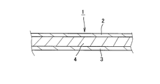
- FIG. 1 is a partial cross-sectional view showing an impact absorbing structure according to an embodiment of the present invention.
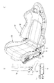
- FIG. 2 is a perspective view showing a seat structure for an automobile provided with a seat cushion portion and a seat back portion using the shock absorbing structure of the embodiment.
- FIG. 3 is a perspective view of the seat structure of FIG. 2 as viewed from the back.
- FIG. 4 is a cross-sectional view of the concavo-convex portion of the shell-type frame member employing the shock absorbing structure of the above embodiment.
- 5 (a) to 5 (c) are graphs showing the results of the tensile stress of each test piece of Test Example 1
- FIG. 5 (d) is a graph showing the tensile stress of each test piece of Comparative Example 1. is there.
- FIGS. 5A to 6D are graphs showing only the average values of FIGS. 5A to 5D.
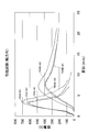
- FIG. 7 is a diagram showing the results of a tensile test in the roll direction of the biaxial woven fabric alone and the 4-axis woven fabric used in Test Example 1 and Test Example 2.
- FIG. 8 is a diagram showing the results of a tensile test in the bias direction of the biaxial woven fabric alone and the 4-axis woven fabric used in Test Example 1 and Test Example 2.
- FIG. 9 is a diagram showing the results of a tensile test in the width direction of the biaxial woven fabric alone and the 4-axis woven fabric used in Test Example 1 and Test Example 2.
- FIG. 7 is a diagram showing the results of a tensile test in the roll direction of the biaxial woven fabric alone and the 4-axis woven fabric used in Test Example 1 and Test Example 2.
- FIG. 8 is a diagram showing the results of a tensile test in the bias direction of the biaxial woven fabric alone
- FIG. 10 is a diagram illustrating a state in the vicinity of the left and right uneven portions of the shell-type frame member after the backward moment experiment is performed in Test Example 3.
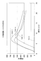
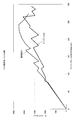
- FIG. 11 is a graph comparing the rear moment of the seat structure of Test Example 3 and the seat structure formed of the carbon shell.
- 12 (a) and 12 (b) show a side frame cover having a substantially L-shaped cross section manufactured by a laminate in which a biaxial woven fabric is sandwiched between two sheet members made of synthetic resin via an adhesive.
- FIG. 1 is a partial cross-sectional view showing an example of an impact absorbing structure 1 according to the present embodiment.
- the shock absorbing structure 1 of the present embodiment is composed of a laminated body in which a cloth-made planar member 4 is sandwiched between two synthetic resin-made planar members 2, 3. Has been. One planar member 2 and the cloth planar member 4, and the cloth planar member 4 and the other planar member 3 are joined to each other via an adhesive.
- the synthetic resin planar members 2 and 3 for example, those made of a thermosetting resin such as an unsaturated polyester resin can be used. Further, a fiber reinforced plastic in which glass fiber or the like is added to a thermosetting resin such as an unsaturated polyester resin can also be used.
- the cloth-made planar member 4 is preferably selected from a biaxial woven fabric, a triaxial woven fabric, a four-axial woven fabric, or a three-dimensional solid knitted fabric, and among these, it is more preferable to use a biaxial woven fabric. The point where the biaxial woven fabric is preferable will be described in detail in a test example described later.
- the three-dimensional solid knitted fabric is knitted by reciprocating a connecting yarn between a pair of ground knitted fabrics positioned at a predetermined interval, and is formed using a double raschel machine or the like. It is preferable to use the one in the range of 2 to 6 mm, and more preferably in the range of 2 to 4 mm.
- the impact-absorbing structure 1 is obtained by, for example, molding the planar members 2 and 3 made of synthetic resin in advance, one of the planar members 2, the fabric planar member 4, and the fabric planar member 4.
- the other planar member 3 can be manufactured by joining each via an adhesive. Moreover, it can also manufacture by sticking a fiber on both surfaces of the cloth-made planar member 4 via an adhesive and laminating a synthetic resin material on the fiber.
- an adhesive agent a synthetic rubber type adhesive agent and a thermosetting adhesive agent are used, for example.
- FIGS. 2 and 3 are views showing a vehicle seat structure 10 including a seat cushion portion 20 and a seat back portion 30.
- This is a bucket seat type seat structure
- the seat back portion 30 is formed by covering a shell type frame member 31 formed by curving a plate-like member with a skin material such as a three-dimensional knitted fabric.
- the configuration of the shock absorbing structure 1 shown in FIG. 1 is adopted as the shell type frame member 31.
- the shell-type frame member 31 of the present embodiment is composed of the planar members 2 and 3 made of synthetic resin, and the planar member 4 made of cloth made of a biaxial woven fabric sandwiched between both by an adhesive. Is done.
- the planar members 2 and 3 made of synthetic resin and a cloth-made frame member 31 are used.
- the laminate composed of the planar member 4 is preferably in the range of 1 to 4 mm in thickness.
- the shell frame member 31 is thin, as shown in FIGS. 2 and 3, as shown in FIG. 2 and FIG. Is preferred.
- the cloth-made planar member 4 is longer than the peripheral length L1, and the surplus portion (slack portion) 4a is generated. Is preferably laminated.
- Test Example 1 Polyethylene naphthalate (PEN) fiber made by Teijin Limited between fiber reinforced plastics based on unsaturated polyester resin for general lamination (made by Kyushu Paint Industry Co., Ltd., product name: “POLYKYUTO PC-420 TN”)
- PEN polyethylene naphthalate
- POLYKYUTO PC-420 TN unsaturated polyester resin for general lamination
- a laminate in which a biaxial woven fabric (length: 20 pieces / inch, width: 20 pieces / inch) formed from (1100 dtex) was sandwiched was produced.
- glass fiber which is a reinforcing material, is bonded to both sides of a biaxial woven fabric with a synthetic rubber adhesive (US, Airtech, spray synthetic rubber adhesive, trade name: AIRTAC 2).
- the above-mentioned general polyester unsaturated polyester resin was laminated and molded.
- a test piece was prepared from this laminate.
- the test pieces are those in which the direction along the winding direction (roll direction) of the biaxial fabric provided by the roll is the tensile direction, the diagonal direction (bias direction) is the tensile direction, and the width direction is tensile.
- Three pieces (n1, n2, n3) were prepared for each direction.
- the tensile stress and Izod impact strength were determined.
- the tensile stress was measured by a tensile test specified in JIS K7113.
- the test piece used in the tensile test was prepared according to JIS K7139 (cited standard ISO 527-2).
- the Izod impact strength was measured by an Izod impact test specified in JIS K7110.
- the test piece used in the Izod impact test was prepared in accordance with JIS K7139 (cited standard ISO 180).
- the tensile stress is as shown in Table 1.
- t is the thickness of each test piece (thickness as a laminate)
- Wc is the width of each test piece.
- Table 2 shows a laminated body in which planar members made of synthetic resin are laminated without using a biaxial woven fabric, specifically, glass fibers are joined together using the same adhesive as described above. It is the tensile stress of the laminated body (same kind laminated body (comparative example 1)) which laminated
- FIG. 5 is a graph showing the tensile stress in Table 2.
- the biaxial woven fabric is not interposed, and the cut out test piece has no directionality. Measurements were made on three cut specimens, and the average was obtained.
- FIG. 6 is a graph showing only the average values shown in FIG. Among these, FIGS. 6 (a) to 6 (c) also show the average values of the same type of laminated body of FIG. 6 (d).
- the tensile stress of the homogenous laminate of Comparative Example 1 is 75.9 MPa, whereas the laminate of Test Example 1 is the average of each test piece.
- the roll direction was 52.4 MPa
- the bias direction was 48.8 MPa
- the width direction was 57.4 MPa
- the reduction rates were 31.0%, 35.7%, and 24.4%, respectively.
- the fact that the tensile stress of a heterogeneous laminate laminated with an adhesive via a biaxial fabric is smaller than the tensile stress of the same type laminate means that between the biaxial fabric and each fiber reinforced plastic (glass fiber).
- the Izod impact strength was 46.9 kJ / m 2 for the homogenous laminate of Comparative Example 1, whereas the laminate of Test Example 1 was in the roll direction. : 33.7 kJ / m 2 , bias direction: 31.9 kJ / m 2 , width direction: 28.8 kJ / m 2 , and the decrease rates were 28.1%, 32.0%, and 38.6%, respectively. there were. Therefore, it can be seen that the laminate of Test Example 1 has a lower Izod impact strength than that of the same type of laminate of Comparative Example 1, and is useful for absorbing impact energy accordingly.
- Test Example 2 instead of the biaxial woven fabric of Test Example 1, a laminate (Test Example 2) in which a 4-axial woven fabric formed using aramid fibers (trademark “Technola” manufactured by Teijin Products Co., Ltd.) was manufactured. Also in Test Example 2, the direction along the winding direction (roll direction) of the roll of the 4-axis woven fabric becomes the tensile direction, the diagonal direction (bias direction) becomes the tensile direction, and the width direction becomes the tensile direction. Three pieces (n1, n2, n3) of each were prepared. For each specimen, the tensile stress and Izod impact strength were determined. In addition, the specification of the test piece and the method of each test are exactly the same as in the case of Test Example 1. Table 5 shows the results of the tensile stress obtained by the tensile test.
- the tensile stress of the same type laminate of Comparative Example 1 is 75.9 MPa (see Table 2), whereas from Table 5, the laminate of Test Example 1 is the average value of each test piece, in the roll direction: 70. 7 MPa, bias direction: 74.8 MPa, width direction: 62.8 MPa, and the reduction rates were 6.9%, 1.4%, and 17.3%, respectively.
- the tensile stress of the heterogeneous laminate obtained by laminating the 4-axis fabric using the adhesive is smaller than the tensile stress of the same-type laminate, and the 4-axis fabric and each fiber-reinforced plastic (glass fiber) It can be seen that delamination occurs between and the impact energy can be absorbed by the reduced tensile stress.
- the rate of decrease in tensile stress when compared with the same type laminate of Comparative Example 1 is biaxial.
- the woven fabric is larger, and it can be said that it is preferable to use a biaxial woven fabric in terms of absorption of impact energy.
- the tensile stress is lower than that of the same type of laminate in Comparative Example 1 in the case of the laminate of Test Example 2 in which a 4-axis fabric is interposed.
- the decrease rate of Test Example 1 is in the range of 24.4 to 35.7%, and the decrease rate of Test Example 2 is in the range of 1.4 to 17.3%.
- the reduction rate greatly exceeds 40%, it is considered that the strength is too low. Therefore, the reduction rate is 40% or less, preferably 20 to 40% including the range of the reduction rate of the biaxial woven fabric. Is desirable.
- the Izod impact strength of the laminate of Test Example 2 was as follows: roll direction: 44.1 kJ / m 2 , bias direction: 48.3 kJ / m 2 , lateral direction: 49.6 kJ / It was m 2.
- the roll direction was 6.0% lower than the Izod impact strength of the same laminate of Comparative Example 1: 46.9 kJ / m 2 (see Table 4), but the bias direction and the lateral direction were Comparative Example 1. It exceeded that of the same type of laminate.
- the laminate of Test Example 1 using the biaxial woven fabric having a value smaller than that of the same laminate of Comparative Example 1 is more reliably impacted by delamination. Absorption function can be demonstrated. In particular, human damage in the case of a rear collision can be reduced.
- the reduction rate of the Izod impact strength is too low to maintain the originally required strength. Therefore, the reduction rate is 40% or less, and preferably the reduction rate of the biaxial woven fabric (28.1 to 38.6%) and 20-40% are desirable.
- each test piece cut out in the roll direction, the bias direction, and the width direction is obtained for the biaxial woven fabric and the 4-axial woven fabric in the same manner as in Test Example 1.
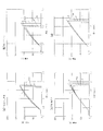
- a tensile test was performed. The results are shown in FIGS. In FIGS. 7 to 9, “PEN” indicates a biaxial woven test piece, and “TNRB” indicates a 4-axial woven test piece.
- PEN indicates a biaxial woven test piece
- TNRB indicates a 4-axial woven test piece.
- Test Example 3 A shell-type frame member 31 was manufactured using a laminate (average thickness: 2.3 mm) having the same configuration as the test piece of Test Example 1. Then, the shell-type frame member 31 was employed in the seat back portion 30, and the seat structure 10 (see FIGS. 2 and 3) in which the seat back portion 30 was coupled to the seat cushion portion 20 via a reclining knuckle was manufactured.
- a rear moment experiment was conducted using this seat structure 10. This experiment is performed by applying a load to the seat back portion backward with a back pan simulating the shape of the back of a person in a state where the seat structure is assembled.
- FIG. 10 is a view showing a state in the vicinity of the left and right uneven portions 31a of the shell-type frame member 31 after the backward moment experiment.
- the synthetic resin on the surface was whitened, and the biaxial woven fabric was not torn and the surface layer and the lower layer were made of a synthetic resin planar member. I understand. Therefore, delamination occurs between the synthetic resin and the biaxial woven fabric, and the impact energy generated by the impact is absorbed by this delamination.
- FIG. 11 is a graph comparing the rear moments of the seat structure of Test Example 3 and the seat structure composed of the carbon shell.
- the seat structure of Test Example 3 has an increased absolute value of the rear moment and a reduced amount of frame deflection to the rear. .
- the difference between the two is the difference in energy absorption due to delamination.
- the phenomenon that the absolute value of the rear moment is increased, the impact load concentrated on the reclining knuckle is smaller than that of the seat structure made of carbon shell. This indicates that the difference between the two works as a force for delamination of each planar member of the laminate, and dissipates impact energy.
- Test Example 4 A side frame cover 21 having a substantially L-shaped cross section was produced from the same laminate as in Test Example 1. As shown in FIG. 12, the side frame cover 21 was connected to a substantially side-shaped metal side frame base 22 having a plate thickness of 1.2 mm. Then, a belt anchor 23 was attached to the side frame cover 21 so as to penetrate the side frame cover 21 in the thickness direction, and the base portion of the seat belt 24 was fixed to the belt anchor 23 with a bolt. In this state, a load was applied to the seat belt 24 so that the belt anchor 23 was pulled in a direction perpendicular to the axial direction (the direction of arrow A in FIG. 12).
- the side frame cover 21 was not cracked, and only a deformation such that the diameter of the through hole of the belt anchor 22 was increased. Therefore, it was found that the laminate obtained by sandwiching the biaxial woven fabric used in the above embodiment with the planar member made of synthetic resin can obtain high rigidity in addition to the impact absorbing action by the delamination action.
Landscapes
- Engineering & Computer Science (AREA)
- Aviation & Aerospace Engineering (AREA)
- Transportation (AREA)
- Mechanical Engineering (AREA)
- Textile Engineering (AREA)
- Laminated Bodies (AREA)
- Seats For Vehicles (AREA)
Abstract
L'invention concerne une structure de siège ayant un poids et une épaisseur réduits. Un élément plat en tissu (4) est pris en sandwich entre les éléments plats de résine synthétique (2, 3) dans des éléments plats (2, 3) et les éléments (4, 2, 3) sont joints ensemble par un agent adhésif pour former un corps stratifié, qui est utilisé pour un élément de cadre de type coque de la structure de siège. Quand le corps stratifié reçoit un impact, une séparation intercouches survient entre les couches formant le corps stratifié. Par conséquent, le corps stratifié a une contrainte de traction et une résistance à l'impact Izod inférieures aux corps stratifiés du même type que ci-dessus qui sont formés en joignant ensemble des éléments plats du même type. En effet, l'énergie de l'impact est consommée lors de la conversion en force pour séparer les éléments plats du corps stratifié l'un de l'autre, et donc l'énergie de l'impact est absorbée. L'élément de cadre de type coque pouvant absorber lui-même un impact, l'élément de cadre et la structure de siège utilisant l'élément de cadre peuvent être encore réduits en poids et en épaisseur.
Priority Applications (2)
| Application Number | Priority Date | Filing Date | Title |
|---|---|---|---|
| EP20080867369 EP2236352B1 (fr) | 2007-12-27 | 2008-12-22 | Structure d'absorption d'impact, element de cadre de type coque et structure de siege |
| US12/810,556 US8376456B2 (en) | 2007-12-27 | 2008-12-22 | Impact absorbing structural body, shell type frame member and seat structure |
Applications Claiming Priority (2)
| Application Number | Priority Date | Filing Date | Title |
|---|---|---|---|
| JP2007-338226 | 2007-12-27 | ||
| JP2007338226A JP5255831B2 (ja) | 2007-12-27 | 2007-12-27 | 衝撃吸収構造体、シェル型フレーム部材及び座席構造 |
Publications (1)
| Publication Number | Publication Date |
|---|---|
| WO2009084505A1 true WO2009084505A1 (fr) | 2009-07-09 |
Family
ID=40824219
Family Applications (1)
| Application Number | Title | Priority Date | Filing Date |
|---|---|---|---|
| PCT/JP2008/073320 Ceased WO2009084505A1 (fr) | 2007-12-27 | 2008-12-22 | Structure d'absorption d'impact, élément de cadre de type coque et structure de siège |
Country Status (4)
| Country | Link |
|---|---|
| US (1) | US8376456B2 (fr) |
| EP (1) | EP2236352B1 (fr) |
| JP (1) | JP5255831B2 (fr) |
| WO (1) | WO2009084505A1 (fr) |
Families Citing this family (15)
| Publication number | Priority date | Publication date | Assignee | Title |
|---|---|---|---|---|
| US8733834B2 (en) * | 2011-04-29 | 2014-05-27 | Lear Corporation | Trim assembly |
| WO2012169906A1 (fr) * | 2011-06-07 | 2012-12-13 | Composite Helicopter Holdings Limited | Hélicoptère |
| JP5921767B2 (ja) | 2012-05-07 | 2016-05-24 | ジョンソン コントロールズ テクノロジー カンパニーJohnson Controls Technology Company | 車両座席の垂直調整用の座席調整装置 |
| DE102012013208B4 (de) | 2012-05-07 | 2019-07-25 | Adient Luxembourg Holding S.À R.L. | Sitzteil eines Fahrzeugsitzes |
| US9580175B2 (en) * | 2013-04-04 | 2017-02-28 | Franklin Products, Inc. | Aircraft seat back assembly |
| GB2515576A (en) * | 2013-06-28 | 2014-12-31 | Gordon Murray Design Ltd | Vehicle Seat |
| JP2015098299A (ja) * | 2013-11-20 | 2015-05-28 | トヨタ紡織株式会社 | 乗物用シート |
| DE102013224927A1 (de) * | 2013-12-04 | 2015-06-11 | Bayerische Motoren Werke Aktiengesellschaft | Tragendes, flächiges Formteil aus einem Mehrschichtfaserverbundwerkstoff, insbesondere für eine Fahrzeugkarosserie |
| KR101560092B1 (ko) * | 2014-05-19 | 2015-10-13 | 김수열 | 충격 강도 향상을 위한 이중 구조의 합성수지재 곡물 포장지 |
| FR3024432B1 (fr) * | 2014-08-01 | 2018-02-02 | Epsilon Composite | Tube de structure de type hybride, notamment pour siege aeronautique |
| JP6527418B2 (ja) * | 2015-07-31 | 2019-06-05 | トヨタ紡織株式会社 | 乗物用シート |
| JP6783621B2 (ja) * | 2016-10-26 | 2020-11-11 | 株式会社タチエス | 車両用シート |
| JP6994840B2 (ja) * | 2017-04-03 | 2022-01-14 | 株式会社ジャムコ | 背面シェル構造体及び座席ユニット |
| US10308203B2 (en) * | 2017-06-20 | 2019-06-04 | Ford Global Technologies, Llc | Stab proof back panel for law enforcement vehicle |
| US10494062B2 (en) | 2017-11-10 | 2019-12-03 | Robert Kohen | Marine seat with safety rollback |
Citations (11)
| Publication number | Priority date | Publication date | Assignee | Title |
|---|---|---|---|---|
| JPH0687185A (ja) * | 1992-07-22 | 1994-03-29 | Mitsui Toatsu Chem Inc | 積層成形品 |
| JP2000281803A (ja) * | 1999-04-01 | 2000-10-10 | Sekisui Chem Co Ltd | 損傷修復複合材及びその製造方法並びに修復方法 |
| JP2003182427A (ja) | 2001-12-20 | 2003-07-03 | Delta Tooling Co Ltd | 衝撃吸収構造及び座席構造 |
| JP2004001729A (ja) * | 2002-04-26 | 2004-01-08 | Toyota Central Res & Dev Lab Inc | 車両用シート |
| WO2004007238A1 (fr) | 2002-07-17 | 2004-01-22 | Delta Tooling Co., Ltd. | Structure de siege |
| JP2004141545A (ja) | 2002-10-28 | 2004-05-20 | Delta Tooling Co Ltd | 座席構造 |
| JP2004188164A (ja) | 2002-03-27 | 2004-07-08 | Delta Tooling Co Ltd | 座席構造 |
| JP2004347577A (ja) | 2003-05-21 | 2004-12-09 | Delta Tooling Co Ltd | 座席構造及び荷重検出装置 |
| JP2006077815A (ja) * | 2004-09-07 | 2006-03-23 | Nissan Motor Co Ltd | エネルギ吸収部材及びそれを用いた自動車用フード |
| JP2007283758A (ja) * | 2006-03-24 | 2007-11-01 | Du Pont Toray Co Ltd | 高機能コンポジット |
| JP2007313907A (ja) * | 2004-08-23 | 2007-12-06 | Delta Tooling Co Ltd | シートフレーム、シート構造及びシートフレームの製造方法 |
Family Cites Families (15)
| Publication number | Priority date | Publication date | Assignee | Title |
|---|---|---|---|---|
| JPS55150348A (en) * | 1979-05-11 | 1980-11-22 | Mitsui Petrochemical Ind | Seat |
| DE3049425C2 (de) * | 1980-12-30 | 1991-09-05 | Messerschmitt-Bölkow-Blohm GmbH, 8000 München | Aufprall-Schutz-Bauteil |
| US5514448A (en) | 1992-07-22 | 1996-05-07 | Mitsui Toatsu Chemicals, Inc. | Laminated molding |
| ATA20593A (de) * | 1993-02-05 | 1998-08-15 | Greiner & Soehne C A | Fahrzeugsitz, insbesondere für flugzeuge |
| KR100923359B1 (ko) * | 2001-08-15 | 2009-10-23 | 다우 글로벌 테크놀로지스 인크. | 개선된 시트 시스템 |
| US6854805B2 (en) | 2002-03-27 | 2005-02-15 | Delta Tooling Co., Ltd. | Seat structure |
| US6896324B1 (en) * | 2002-04-19 | 2005-05-24 | Adam Aircraft Industries | Hybrid composite-metal energy absorbing seat |
| US7134718B2 (en) | 2002-04-26 | 2006-11-14 | Kabushiki Kaisha Toyota Chuo Kenkyusho | Vehicle seat |
| US7128373B2 (en) * | 2002-09-27 | 2006-10-31 | Dow Global Technologies, Inc. | Seating system and method of forming same |
| US7070242B2 (en) * | 2002-10-02 | 2006-07-04 | Simula, Inc. | Armor system with monolithic ceramic shell |
| US7111888B1 (en) * | 2003-09-09 | 2006-09-26 | Motorsports Builders, Llc | Molded safety seat |
| FR2869565B1 (fr) * | 2004-04-28 | 2007-08-10 | Eurocopter France | Protection d'une structure composite aux impacts |
| US7716797B2 (en) * | 2006-12-22 | 2010-05-18 | The Boeing Company | Composite seat pan structure for a lightweight aircraft seat assembly |
| US7717519B2 (en) * | 2006-12-22 | 2010-05-18 | The Boeing Company | Composite seat back structure for a lightweight aircraft seat assembly |
| JP5470598B2 (ja) * | 2008-03-03 | 2014-04-16 | 株式会社デルタツーリング | 構造材及び輸送機器用座席構造 |
-
2007
- 2007-12-27 JP JP2007338226A patent/JP5255831B2/ja not_active Expired - Fee Related
-
2008
- 2008-12-22 WO PCT/JP2008/073320 patent/WO2009084505A1/fr not_active Ceased
- 2008-12-22 EP EP20080867369 patent/EP2236352B1/fr not_active Not-in-force
- 2008-12-22 US US12/810,556 patent/US8376456B2/en not_active Expired - Fee Related
Patent Citations (11)
| Publication number | Priority date | Publication date | Assignee | Title |
|---|---|---|---|---|
| JPH0687185A (ja) * | 1992-07-22 | 1994-03-29 | Mitsui Toatsu Chem Inc | 積層成形品 |
| JP2000281803A (ja) * | 1999-04-01 | 2000-10-10 | Sekisui Chem Co Ltd | 損傷修復複合材及びその製造方法並びに修復方法 |
| JP2003182427A (ja) | 2001-12-20 | 2003-07-03 | Delta Tooling Co Ltd | 衝撃吸収構造及び座席構造 |
| JP2004188164A (ja) | 2002-03-27 | 2004-07-08 | Delta Tooling Co Ltd | 座席構造 |
| JP2004001729A (ja) * | 2002-04-26 | 2004-01-08 | Toyota Central Res & Dev Lab Inc | 車両用シート |
| WO2004007238A1 (fr) | 2002-07-17 | 2004-01-22 | Delta Tooling Co., Ltd. | Structure de siege |
| JP2004141545A (ja) | 2002-10-28 | 2004-05-20 | Delta Tooling Co Ltd | 座席構造 |
| JP2004347577A (ja) | 2003-05-21 | 2004-12-09 | Delta Tooling Co Ltd | 座席構造及び荷重検出装置 |
| JP2007313907A (ja) * | 2004-08-23 | 2007-12-06 | Delta Tooling Co Ltd | シートフレーム、シート構造及びシートフレームの製造方法 |
| JP2006077815A (ja) * | 2004-09-07 | 2006-03-23 | Nissan Motor Co Ltd | エネルギ吸収部材及びそれを用いた自動車用フード |
| JP2007283758A (ja) * | 2006-03-24 | 2007-11-01 | Du Pont Toray Co Ltd | 高機能コンポジット |
Non-Patent Citations (1)
| Title |
|---|
| See also references of EP2236352A4 * |
Also Published As
| Publication number | Publication date |
|---|---|
| JP2009154821A (ja) | 2009-07-16 |
| EP2236352A1 (fr) | 2010-10-06 |
| EP2236352B1 (fr) | 2015-04-15 |
| US20110278901A1 (en) | 2011-11-17 |
| JP5255831B2 (ja) | 2013-08-07 |
| US8376456B2 (en) | 2013-02-19 |
| EP2236352A4 (fr) | 2012-12-26 |
Similar Documents
| Publication | Publication Date | Title |
|---|---|---|
| JP5255831B2 (ja) | 衝撃吸収構造体、シェル型フレーム部材及び座席構造 | |
| JP5470598B2 (ja) | 構造材及び輸送機器用座席構造 | |
| US8528982B2 (en) | Seat | |
| GB2477234A (en) | Aircraft seat leg fabrication method | |
| WO2004007238A1 (fr) | Structure de siege | |
| WO2011018930A1 (fr) | Siège de véhicule | |
| JP4483409B2 (ja) | シート | |
| JP6358280B2 (ja) | 車体パネルの取付構造 | |
| JP5952990B2 (ja) | 金属樹脂複合体 | |
| JP6235384B2 (ja) | 自動車の車体構造 | |
| JP5669288B2 (ja) | シェル型フレーム部材及び座席構造 | |
| JP5771020B2 (ja) | 車両用シートバックフレーム構造 | |
| CN105793107B (zh) | 座椅框架 | |
| JP6686700B2 (ja) | 繊維強化樹脂部品のフランジ製造方法及び繊維強化樹脂部品のフランジ構造 | |
| JP7537333B2 (ja) | 複合部材、自動車用シート、自動車用部品 | |
| WO2018061887A1 (fr) | Siège de véhicule | |
| JP2021059043A (ja) | 芯材及び複合部材 | |
| WO2015076265A1 (fr) | Armature de siège | |
| JP2017081189A (ja) | 車両の車体構造 | |
| WO2018174037A1 (fr) | Véhicule inclinable | |
| KR20120140352A (ko) | 컴포트가 향상된 복판형 시트 백 프레임 | |
| TW201838860A (zh) | 傾斜車輛 | |
| JP2004051030A (ja) | Frp製自動車ルーフ | |
| JP2017165255A (ja) | 車両用シート |
Legal Events
| Date | Code | Title | Description |
|---|---|---|---|
| 121 | Ep: the epo has been informed by wipo that ep was designated in this application |
Ref document number: 08867369 Country of ref document: EP Kind code of ref document: A1 |
|
| NENP | Non-entry into the national phase |
Ref country code: DE |
|
| WWE | Wipo information: entry into national phase |
Ref document number: 2008867369 Country of ref document: EP |
|
| WWE | Wipo information: entry into national phase |
Ref document number: 12810556 Country of ref document: US |