WO2009084552A1 - Elément lame, et appareil d'usinage de bord pour l'élément lame - Google Patents
Elément lame, et appareil d'usinage de bord pour l'élément lame Download PDFInfo
- Publication number
- WO2009084552A1 WO2009084552A1 PCT/JP2008/073494 JP2008073494W WO2009084552A1 WO 2009084552 A1 WO2009084552 A1 WO 2009084552A1 JP 2008073494 W JP2008073494 W JP 2008073494W WO 2009084552 A1 WO2009084552 A1 WO 2009084552A1
- Authority
- WO
- WIPO (PCT)
- Prior art keywords
- blade
- edge
- plasma ion
- gun
- plasma
- Prior art date
- Legal status (The legal status is an assumption and is not a legal conclusion. Google has not performed a legal analysis and makes no representation as to the accuracy of the status listed.)
- Ceased
Links
Images


Classifications
-
- B—PERFORMING OPERATIONS; TRANSPORTING
- B26—HAND CUTTING TOOLS; CUTTING; SEVERING
- B26B—HAND-HELD CUTTING TOOLS NOT OTHERWISE PROVIDED FOR
- B26B9/00—Blades for hand knives
-
- B—PERFORMING OPERATIONS; TRANSPORTING
- B26—HAND CUTTING TOOLS; CUTTING; SEVERING
- B26B—HAND-HELD CUTTING TOOLS NOT OTHERWISE PROVIDED FOR
- B26B21/00—Razors of the open or knife type; Safety razors or other shaving implements of the planing type; Hair-trimming devices involving a razor-blade; Equipment therefor
- B26B21/54—Razor-blades
-
- C—CHEMISTRY; METALLURGY
- C23—COATING METALLIC MATERIAL; COATING MATERIAL WITH METALLIC MATERIAL; CHEMICAL SURFACE TREATMENT; DIFFUSION TREATMENT OF METALLIC MATERIAL; COATING BY VACUUM EVAPORATION, BY SPUTTERING, BY ION IMPLANTATION OR BY CHEMICAL VAPOUR DEPOSITION, IN GENERAL; INHIBITING CORROSION OF METALLIC MATERIAL OR INCRUSTATION IN GENERAL
- C23F—NON-MECHANICAL REMOVAL OF METALLIC MATERIAL FROM SURFACE; INHIBITING CORROSION OF METALLIC MATERIAL OR INCRUSTATION IN GENERAL; MULTI-STEP PROCESSES FOR SURFACE TREATMENT OF METALLIC MATERIAL INVOLVING AT LEAST ONE PROCESS PROVIDED FOR IN CLASS C23 AND AT LEAST ONE PROCESS COVERED BY SUBCLASS C21D OR C22F OR CLASS C25
- C23F4/00—Processes for removing metallic material from surfaces, not provided for in group C23F1/00 or C23F3/00
-
- Y—GENERAL TAGGING OF NEW TECHNOLOGICAL DEVELOPMENTS; GENERAL TAGGING OF CROSS-SECTIONAL TECHNOLOGIES SPANNING OVER SEVERAL SECTIONS OF THE IPC; TECHNICAL SUBJECTS COVERED BY FORMER USPC CROSS-REFERENCE ART COLLECTIONS [XRACs] AND DIGESTS
- Y10—TECHNICAL SUBJECTS COVERED BY FORMER USPC
- Y10T—TECHNICAL SUBJECTS COVERED BY FORMER US CLASSIFICATION
- Y10T83/00—Cutting
- Y10T83/929—Tool or tool with support
Definitions
- the present invention relates to a blade member used for a razor or the like, and an apparatus for processing a blade edge of the blade member.
- the cutting blade is subjected to ion implantation to improve the hardness of the cutting blade.
- reactive ion etching is applied to the blade edge to increase the sharpness of the blade edge.
- the present invention improves a processing technique by ion beam processing or plasma ion implantation processing, and provides a blade member having a more excellent blade edge, and a processing apparatus capable of efficiently processing such a blade edge. It is intended to provide.
- a plasma ion gun is used with respect to the blade edge of the blade group within the vacuum chamber, and argon is used as a medium with an argon gas pressure of 0.1 to 1 Pa and the blade group.
- Ion beam processing was performed with a bias voltage of 0.1 to 1000 V and a processing time of 5 to 300 minutes. Thereby, the sharpness of a blade edge can be raised and sharpness can be improved.
- the blade edge of the blade group having a tip edge angle of 10 ° to 35 ° and a blade edge flash height of 0.1 to 10 ⁇ m.
- ion beam machining is continued after plasma ion implantation in the same vacuum chamber to efficiently process the blade edge, leaving a hardened layer on the blade edge to increase rigidity, and the blade edge. 11 can finish the whole blade line uniformly and can improve sharpness.
- This plasma ion implantation process and the subsequent ion beam process may be repeated.
- the depth from the tip of the blade edge is 0.1 to 1 using a plasma ion gun and using argon as a medium with respect to the blade edge of the blade group in the vacuum chamber. Ion beam processing was performed at a depth of 0.1 to 1.5 ⁇ m in a thickness direction of the blade edge of 0.5 ⁇ m. Thereby, the sharpness of the blade edge 11 can be raised and the sharpness can be enhanced.
- a plurality of blade body groups inserted in a skewer and stacked in the horizontal direction are rotated while revolving with each other, and the blades of each blade body group are rotated.
- the edge was subjected to ion beam processing using a plasma ion gun and argon as a medium.
- ion beam machining is performed on each blade group on average, and the sharpness is increased on the whole of the blade edge to increase sharpness. be able to.
- a plurality of blade body groups inserted in the vacuum chamber and stacked along the horizontal direction H are revolved and rotated in the vacuum chamber.
- a rotating body and a plasma ion gun arranged in parallel with the rotating body are provided, and ion beam processing is performed on the blade edge of each blade group using argon as a medium using the plasma ion gun.
- ion beam processing can be performed on the edge of each blade group on average.
- a blade pressure is applied to the blade edge of the blade body group in the vacuum chamber using a plasma ion implantation gun and nitrogen pressure of 0.5 to 5 Pa by nitrogen plasma.
- Plasma ion implantation was performed at a bias voltage of 0.1 to 1000 V, a filament current of 100 to 200 A, and a processing time of 10 to 1000 minutes.
- the rigidity of the blade edge can be increased to increase the rigidity.
- the blade edge of the blade group having a tip edge angle of 10 ° to 35 ° and a blade edge flash height of 0.1 to 10 ⁇ m in a vacuum chamber.
- plasma ion implantation processing was performed using nitrogen plasma using a plasma ion implantation gun.
- plasma ion implantation can be continued after ion beam processing in the same vacuum chamber to efficiently process the blade edge, and a sufficient hardened layer can be provided over the entire blade edge to increase rigidity. This ion beam processing and subsequent plasma ion implantation processing may be repeated.
- the depth from the tip of the blade edge to the edge of the blade edge is 0.1 by using a plasma ion implantation gun with respect to the blade edge of the blade group in the vacuum chamber and using nitrogen plasma.
- Plasma ion implantation was performed at a thickness of 0.1 to 1.5 ⁇ m and a depth of 0.1 to 1.5 ⁇ m in the thickness direction of the blade edge.
- the rigidity of the blade edge can be increased to increase the rigidity.
- a plurality of blade body groups inserted in a skewer and stacked along the horizontal direction H are rotated while revolving, and each blade body group is rotated.
- the edge of the blade was subjected to plasma ion implantation with nitrogen plasma using a plasma ion implantation gun.
- plasma ion implantation processing is performed on average, and the hardness of the entire blade edge can be increased to increase rigidity. .
- a processing apparatus for a blade edge of a blade member according to a tenth aspect of the present invention is a rotating body that revolves and rotates each of a plurality of blade body groups inserted in a vacuum chamber and stacked in a horizontal direction H in a vacuum chamber. And a plasma ion gun and a plasma ion implantation gun.
- the processing apparatus uses the plasma ion gun to perform ion beam processing on the blade edge of each blade group using argon as a medium, and applies nitrogen plasma to the blade edge of each blade group using the plasma ion implantation gun. Plasma ion implantation processing is performed.
- each blade group rotates while revolving with respect to the plasma ion gun and the plasma ion implantation gun, so that the ion beam machining can be performed on the edge of each blade group on average, and each blade group Plasma ion implantation processing can be performed on the blade edge on average.
- ion beam processing and plasma ion implantation processing can be performed in the same vacuum chamber, it is possible to perform processing of the blade edge by making these processing continuous with each other. For example, one of the ion beam processing and the plasma ion implantation processing is performed after the other processing, the plasma ion implantation processing and the subsequent ion beam processing are repeated, or the ion beam processing and the subsequent processing are performed.
- the plasma ion implantation process may be repeated.
- a blade body mounting base 3 is provided at the lower part in the vacuum chamber 2.
- a plasma ion gun 4 that performs ion beam processing using argon as a medium and a plasma ion implantation gun 5 that performs plasma ion implantation processing using nitrogen plasma are arranged in parallel in the upper portion of the vacuum chamber 2 with their positions fixed. Yes.
- a revolving base 6 is supported as a rotating body that rotates around a revolving shaft 6a.
- the revolving table 6 supports a plurality of rotating tables 7 as rotating bodies that rotate about the rotating shaft 7a.
- the stacking direction of the blade body 10 is orthogonal to the revolution axis 6a and the rotation axis 7a.
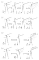
- each blade body group 9 revolves and revolves, and in that state, for example, according to the processing procedure shown in FIGS. 4 (a), (b), (c), and (d).
- Each blade group 9 is subjected to ion beam processing and plasma ion implantation processing.
- the revolving table 6 and the rotating table 7 may repeat not only rotation in the same direction (forward rotation) but also forward rotation and reverse rotation alternately.
- a band-shaped blade material in which a plurality of blade bodies 10 (10A) are connected along the longitudinal direction is generated at the blade edge 11 of each blade body 10.
- the burr 12 having a height of 0.1 to 10 ⁇ m is removed by leather grinding, and the edge 11 thereof is made slightly obtuse.
- belt-shaped blade body raw material is cut
- the blade edge 11 of each blade body 10 (10C1) is subjected to ion beam machining to sharpen the blade edge 11, and further, the blade edge 11 of each blade body 10 (10D1) is subjected to plasma ion implantation to obtain the blade edge.
- the edge 11 is cured.
- 0.05 mm or more is preferable.
- the ⁇ 10 ⁇ m burr 12 is removed by leather grinding, the edge 11 thereof is made slightly obtuse, and the blade body material is cut for each blade body 10 (10B).
- the blade edge 11 of each blade body 10 (10D2) is subjected to plasma ion implantation processing to cure the blade edge 11, and further, the edge 11 of each blade body 10 (10C2) is subjected to ion beam processing, The blade edge 11 is sharpened.
- the blade edge 11 of each blade body 10 is made of the same blade-shaped blade body material in which a plurality of blade bodies 10 (10A) are connected without performing the above-mentioned surface grinding.
- the blade body material is cut for each blade body 10 while leaving the generated flash 12.
- the edge 11 of each blade 10 (10C3) is subjected to ion beam processing to sharpen the edge 11 and remove the flash 12, and further plasma ions are applied to the edge 11 of each blade 10 (10D3).
- the blade edge 11 is cured by performing an injection process.
- the crests 13a and the troughs 13b are alternately continued, and the blade line 13 has a wave shape, and the crest 13a.
- the valley 13b have a height difference of 0.1 to 1 ⁇ m, and the crest 13a or the valley 13b is formed 5 to 30 times per 10 ⁇ m of the blade.
- the tip angle ⁇ of the blade edge 11 is preferably 20 degrees or less, and more preferably 16 degrees or less, particularly when no surface grinding is performed.
- the vacuum chamber 2 is cleaned after the ion beam processing or plasma ion implantation processing.
- the argon gas is introduced into each of the plasma ion guns 4 to form a plasma state in which argon ions (Ar + ) and electrons e ⁇ are ionized. Only the argon ions are extracted by a magnetic field (not shown) and irradiated onto the blade edge, and the blade edge is processed to sharpen the blade edge so that the argon ion repels the metal of the blade edge.
- the ionization voltage is set to 2 to 3 kV
- the bias voltage for the blade group 9 is set to 0.1 to 1000 V
- the argon pressure is set to 0.1 to 1 Pa
- the processing time is set to 5 to 300 minutes.
- the depth from the tip 11a of the blade edge 11 is 0.1 to 1.5 ⁇ m and the depth of the blade edge 11 in the thickness direction is 0.1 to 30 ⁇ m along the both blade surfaces 11b shown in FIG.
- the temperature of the blade edge 11 is 150 ° C. or higher.
- the nitrogen gas becomes a plasma state.
- nitrogen plasma (N + ) collides and is injected into the blade edge to generate Fe 4 N, and the blade edge is hardened.
- the filament current is 100 to 200 A
- the discharge current is 100 to 300 A
- the bias voltage for the blade group 9 is 0.1 to 1000 V
- the nitrogen pressure is 0.5 to 5 Pa
- the treatment time is 10 Set to ⁇ 1000 minutes.
- the discharge current is a current that flows between the ion gun and the blade group in order to cause nitrogen plasma (N + ) to collide and inject into the blade edge.
- the depth from the tip 11a of the blade edge 11 is 0.1 to 1.5 ⁇ m over the entire length of the blade edge 11 in the range of the length of 0.1 to 3 mm along the both blade surfaces 11b shown in FIG.
- the thickness of the blade edge 11 is 0.1 to 1.5 ⁇ m in depth
- the temperature of the blade edge 11 is 200 ° C. or higher
- the hardness of the blade edge 11 is 1200 to 2000 Hv.
- the blade edge 11 processed by the procedure shown in FIGS. 4A, 4B, 4C, and 4D is formed so that the two blade surfaces 11b intersect each other as shown in FIG.
- the thickness L between the two blade surfaces 11b at the distance L (depth) from the sharp tip 11a is T
- Table 1 shows the value of the thickness T at the distance L.
- the ideal shape of the blade edge 11 is as follows.
- the distance L from the tip 11a is 0.5 ⁇ m, 1 ⁇ m, 2 ⁇ m, 4 ⁇ m, 10 ⁇ m, 20 ⁇ m, 30 ⁇ m, and 50 ⁇ m.
- the maximum thickness Tmax (0.5 ⁇ m, 0.85 ⁇ m, 1.4 ⁇ m, 2.5 ⁇ m, 4.5 ⁇ m, 7.5 ⁇ m, 11.0 ⁇ m, 16.5 ⁇ m) is the minimum thickness between the 10 blade surfaces 11b. It is obtained when it is in the range between Tmin (0.4 ⁇ m, 0.65 ⁇ m, 1.1 ⁇ m, 2.1 ⁇ m, 4.0 ⁇ m, 6.5 ⁇ m, 9.0 ⁇ m, 14.0 ⁇ m).
- the blade edge 11 When the distance L from the tip 11a is up to 4 ⁇ m, the blade edge 11 is relatively thick and the durability can be improved. When the distance L from the tip 11a is 4 ⁇ m or later, the blade edge 11 is relatively thin and the cutting resistance is reduced. Can be reduced.
- the blade edge 11 is subjected to a film forming process such as DLC (Diamond Like Carbon) or TiCrAlN to improve the strength of the blade edge 11 and round the tip 11a of the blade edge 11 with a radius of curvature of 20 to 50 nm. It is attached to prevent biting into the skin, and the edge 11 thereof is subjected to a fluororesin coating treatment.
- a film forming process such as DLC (Diamond Like Carbon) or TiCrAlN to improve the strength of the blade edge 11 and round the tip 11a of the blade edge 11 with a radius of curvature of 20 to 50 nm. It is attached to prevent biting into the skin, and the edge 11 thereof is subjected to a fluororesin coating treatment.
Landscapes
- Engineering & Computer Science (AREA)
- Mechanical Engineering (AREA)
- Life Sciences & Earth Sciences (AREA)
- Forests & Forestry (AREA)
- Chemical & Material Sciences (AREA)
- Materials Engineering (AREA)
- Metallurgy (AREA)
- Organic Chemistry (AREA)
- Knives (AREA)
- Welding Or Cutting Using Electron Beams (AREA)
- Physical Vapour Deposition (AREA)
Abstract
Dans une enceinte sous vide, le bord de chaque groupe de lames est soumis à un traitement par faisceau d'électrons dans des conditions prédéterminées à l'aide d'un canon à ions plasma et d'argon comme milieu, et est soumis à un traitement d'injection d'ions plasma dans des conditions prédéterminées à l'aide d'un canon à injection d'ions plasma et à l'aide de plasma d'azote. En conséquence, il est possible de fournir un élément lame ayant un bord d'une qualité de coupe améliorée en rendant le tranchant plus important, un élément lame ayant un bord d'une rigidité améliorée en rendant la dureté plus importante, et un appareil d'usinage pouvant usiner efficacement ces bords.
Priority Applications (2)
| Application Number | Priority Date | Filing Date | Title |
|---|---|---|---|
| EP08867886.7A EP2233258B1 (fr) | 2007-12-27 | 2008-12-24 | Procédé d'usinage de bord pour un élément lame |
| US12/734,644 US8522645B2 (en) | 2007-12-27 | 2008-12-24 | Blade member, and edge working apparatus for the blade member |
Applications Claiming Priority (2)
| Application Number | Priority Date | Filing Date | Title |
|---|---|---|---|
| JP2007337779A JP5210627B2 (ja) | 2007-12-27 | 2007-12-27 | 刃部材及び刃部材の刃縁の加工装置 |
| JP2007-337779 | 2007-12-27 |
Publications (1)
| Publication Number | Publication Date |
|---|---|
| WO2009084552A1 true WO2009084552A1 (fr) | 2009-07-09 |
Family
ID=40824266
Family Applications (1)
| Application Number | Title | Priority Date | Filing Date |
|---|---|---|---|
| PCT/JP2008/073494 Ceased WO2009084552A1 (fr) | 2007-12-27 | 2008-12-24 | Elément lame, et appareil d'usinage de bord pour l'élément lame |
Country Status (4)
| Country | Link |
|---|---|
| US (1) | US8522645B2 (fr) |
| EP (1) | EP2233258B1 (fr) |
| JP (1) | JP5210627B2 (fr) |
| WO (1) | WO2009084552A1 (fr) |
Cited By (1)
| Publication number | Priority date | Publication date | Assignee | Title |
|---|---|---|---|---|
| JP2017514667A (ja) * | 2014-05-19 | 2017-06-08 | ザ ジレット カンパニー リミテッド ライアビリティ カンパニーThe Gillette Company Llc | カミソリの刃 |
Families Citing this family (3)
| Publication number | Priority date | Publication date | Assignee | Title |
|---|---|---|---|---|
| JP5924094B2 (ja) | 2012-04-18 | 2016-05-25 | 新明和工業株式会社 | 刃物、その製造方法およびそれを製造するためのプラズマ装置 |
| JP5956855B2 (ja) * | 2012-07-04 | 2016-07-27 | 日本航空電子工業株式会社 | 切れ刃エッジの加工方法及び器具の製造方法 |
| CN107107362B (zh) | 2014-12-22 | 2020-08-04 | 比克-维尔莱克 | 剃须刀片 |
Citations (7)
| Publication number | Priority date | Publication date | Assignee | Title |
|---|---|---|---|---|
| JPS5428379B1 (fr) | 1971-01-21 | 1979-09-17 | ||
| JPH01109648A (ja) * | 1987-10-21 | 1989-04-26 | Nec Corp | ビームプラズマ型イオン銃 |
| JPH03171630A (ja) * | 1989-11-29 | 1991-07-25 | Toshiba Corp | 半導体装置とその製造方法および配線膜形成装置 |
| JPH11191208A (ja) * | 1997-10-23 | 1999-07-13 | Yamaha Corp | 薄膜磁気ヘッドスライダの製造方法 |
| JP2007061212A (ja) | 2005-08-29 | 2007-03-15 | Kai R & D Center Co Ltd | 刃体の刃縁の成形方法 |
| WO2007116522A1 (fr) * | 2006-04-10 | 2007-10-18 | Osg Corporation | Procédé de retrait d'un revêtement diamant |
| JP2007307673A (ja) * | 2006-05-19 | 2007-11-29 | Osg Corp | ダイヤモンド被覆切削部材、およびその製造方法 |
Family Cites Families (11)
| Publication number | Priority date | Publication date | Assignee | Title |
|---|---|---|---|---|
| GB1350594A (en) * | 1970-02-05 | 1974-04-18 | Gillette Industries Ltd | Sharpening cutting edges |
| AU485283B2 (en) * | 1971-05-18 | 1974-10-03 | Warner-Lambert Company | Method of making a razorblade |
| JPH01109643A (ja) | 1987-10-23 | 1989-04-26 | Toshiba Corp | ランプの良否判定方法 |
| GB8821944D0 (en) | 1988-09-19 | 1988-10-19 | Gillette Co | Method & apparatus for forming surface of workpiece |
| JPH04321223A (ja) * | 1991-04-19 | 1992-11-11 | Nippon Telegr & Teleph Corp <Ntt> | イオン注入方法及びイオン注入装置 |
| US5958134A (en) * | 1995-06-07 | 1999-09-28 | Tokyo Electron Limited | Process equipment with simultaneous or sequential deposition and etching capabilities |
| US5724868A (en) * | 1996-01-11 | 1998-03-10 | Buck Knives, Inc. | Method of making knife with cutting performance |
| JP4741056B2 (ja) * | 2000-06-05 | 2011-08-03 | 株式会社貝印刃物開発センター | 刃部材及びその刃先の製造方法 |
| KR100466536B1 (ko) * | 2002-05-10 | 2005-01-15 | 한국원자력연구소 | 이온 조사에 의한 이용기 날의 표면처리 방법 |
| CN1822928A (zh) * | 2003-07-15 | 2006-08-23 | 皇家飞利浦电子股份有限公司 | 具有氮化硬化底板的带镀层的剃削件 |
| JP4321223B2 (ja) * | 2003-11-10 | 2009-08-26 | 株式会社明電舎 | 加熱加工施設の運転制御方法とそのシステム |
-
2007
- 2007-12-27 JP JP2007337779A patent/JP5210627B2/ja active Active
-
2008
- 2008-12-24 WO PCT/JP2008/073494 patent/WO2009084552A1/fr not_active Ceased
- 2008-12-24 US US12/734,644 patent/US8522645B2/en active Active
- 2008-12-24 EP EP08867886.7A patent/EP2233258B1/fr not_active Not-in-force
Patent Citations (7)
| Publication number | Priority date | Publication date | Assignee | Title |
|---|---|---|---|---|
| JPS5428379B1 (fr) | 1971-01-21 | 1979-09-17 | ||
| JPH01109648A (ja) * | 1987-10-21 | 1989-04-26 | Nec Corp | ビームプラズマ型イオン銃 |
| JPH03171630A (ja) * | 1989-11-29 | 1991-07-25 | Toshiba Corp | 半導体装置とその製造方法および配線膜形成装置 |
| JPH11191208A (ja) * | 1997-10-23 | 1999-07-13 | Yamaha Corp | 薄膜磁気ヘッドスライダの製造方法 |
| JP2007061212A (ja) | 2005-08-29 | 2007-03-15 | Kai R & D Center Co Ltd | 刃体の刃縁の成形方法 |
| WO2007116522A1 (fr) * | 2006-04-10 | 2007-10-18 | Osg Corporation | Procédé de retrait d'un revêtement diamant |
| JP2007307673A (ja) * | 2006-05-19 | 2007-11-29 | Osg Corp | ダイヤモンド被覆切削部材、およびその製造方法 |
Cited By (1)
| Publication number | Priority date | Publication date | Assignee | Title |
|---|---|---|---|---|
| JP2017514667A (ja) * | 2014-05-19 | 2017-06-08 | ザ ジレット カンパニー リミテッド ライアビリティ カンパニーThe Gillette Company Llc | カミソリの刃 |
Also Published As
| Publication number | Publication date |
|---|---|
| US8522645B2 (en) | 2013-09-03 |
| EP2233258B1 (fr) | 2019-04-10 |
| US20100288097A1 (en) | 2010-11-18 |
| JP2009153877A (ja) | 2009-07-16 |
| EP2233258A4 (fr) | 2016-05-18 |
| EP2233258A1 (fr) | 2010-09-29 |
| JP5210627B2 (ja) | 2013-06-12 |
Similar Documents
| Publication | Publication Date | Title |
|---|---|---|
| JP5924094B2 (ja) | 刃物、その製造方法およびそれを製造するためのプラズマ装置 | |
| CN1235549C (zh) | 具有高锐度和韧度的手术刀片 | |
| CN101657303B (zh) | 切割元件、装备有切割元件的电动剃须刀以及生产该元件的方法 | |
| WO2009084552A1 (fr) | Elément lame, et appareil d'usinage de bord pour l'élément lame | |
| CN1965768A (zh) | 医用刀 | |
| KR0149521B1 (ko) | 칼날 | |
| JP2012030010A (ja) | 穿刺針およびその製造方法 | |
| JP2012045279A (ja) | 医療用ナイフ | |
| US20170028571A1 (en) | Knife and blade finishing method | |
| WO2009100006A2 (fr) | Méthode et système pour améliorer des lames chirurgicales par l’application d’une technologie de faisceau ionique en grappes gazeuses et lames chirurgicales améliorées | |
| WO2018003272A9 (fr) | Outil de coupe | |
| CN105538348A (zh) | 刀具及该刀具的制造方法 | |
| WO1996030173A1 (fr) | Lames de couteaux | |
| CN113453856B (zh) | 刀和刀的制造方法 | |
| JP2004298562A (ja) | 刃物の表面処理方法とその刃物 | |
| JP2013220554A (ja) | スクライビングホイール及びその製造方法 | |
| KR20240005313A (ko) | 전자빔 표면처리를 이용한 탄소 코팅 접착력 향상 방법 | |
| US20030208912A1 (en) | Method for treating blade of hair clipper by ion irradiation | |
| JP2005152256A (ja) | 往復刃の製造方法及びこれを用いて製造した往復刃 | |
| CN107443592B (zh) | 划线轮及其制造方法 | |
| JP2016064133A (ja) | ストレートナイフの製造方法 | |
| JP6275821B2 (ja) | 鋼部品およびその製造方法 | |
| TWI602667B (zh) | Scoring wheel and its manufacturing method | |
| US20220347876A1 (en) | Metals for razor blade applications | |
| RU2680792C1 (ru) | Электрод-инструмент для комбинированной резки токопроводящих материалов |
Legal Events
| Date | Code | Title | Description |
|---|---|---|---|
| 121 | Ep: the epo has been informed by wipo that ep was designated in this application |
Ref document number: 08867886 Country of ref document: EP Kind code of ref document: A1 |
|
| WWE | Wipo information: entry into national phase |
Ref document number: 12734644 Country of ref document: US |
|
| WWE | Wipo information: entry into national phase |
Ref document number: 2008867886 Country of ref document: EP |
|
| NENP | Non-entry into the national phase |
Ref country code: DE |