WO2009084576A1 - Appareil diffuseur et procédé de fonctionnement de l'appareil diffuseur - Google Patents
Appareil diffuseur et procédé de fonctionnement de l'appareil diffuseur Download PDFInfo
- Publication number
- WO2009084576A1 WO2009084576A1 PCT/JP2008/073562 JP2008073562W WO2009084576A1 WO 2009084576 A1 WO2009084576 A1 WO 2009084576A1 JP 2008073562 W JP2008073562 W JP 2008073562W WO 2009084576 A1 WO2009084576 A1 WO 2009084576A1
- Authority
- WO
- WIPO (PCT)
- Prior art keywords
- air
- diffuser
- supply pipe
- water
- blow water
- Prior art date
- Legal status (The legal status is an assumption and is not a legal conclusion. Google has not performed a legal analysis and makes no representation as to the accuracy of the status listed.)
- Ceased
Links
Images




Classifications
-
- C—CHEMISTRY; METALLURGY
- C02—TREATMENT OF WATER, WASTE WATER, SEWAGE, OR SLUDGE
- C02F—TREATMENT OF WATER, WASTE WATER, SEWAGE, OR SLUDGE
- C02F3/00—Biological treatment of water, waste water, or sewage
- C02F3/02—Aerobic processes
- C02F3/12—Activated sludge processes
- C02F3/20—Activated sludge processes using diffusers
-
- B—PERFORMING OPERATIONS; TRANSPORTING
- B01—PHYSICAL OR CHEMICAL PROCESSES OR APPARATUS IN GENERAL
- B01F—MIXING, e.g. DISSOLVING, EMULSIFYING OR DISPERSING
- B01F23/00—Mixing according to the phases to be mixed, e.g. dispersing or emulsifying
- B01F23/20—Mixing gases with liquids
- B01F23/23—Mixing gases with liquids by introducing gases into liquid media, e.g. for producing aerated liquids
- B01F23/231—Mixing gases with liquids by introducing gases into liquid media, e.g. for producing aerated liquids by bubbling
- B01F23/23105—Arrangement or manipulation of the gas bubbling devices
- B01F23/2311—Mounting the bubbling devices or the diffusers
- B01F23/23114—Mounting the bubbling devices or the diffusers characterised by the way in which the different elements of the bubbling installation are mounted
- B01F23/231143—Mounting the bubbling elements or diffusors, e.g. on conduits, using connecting elements; Connections therefor
-
- B—PERFORMING OPERATIONS; TRANSPORTING
- B01—PHYSICAL OR CHEMICAL PROCESSES OR APPARATUS IN GENERAL
- B01F—MIXING, e.g. DISSOLVING, EMULSIFYING OR DISPERSING
- B01F23/00—Mixing according to the phases to be mixed, e.g. dispersing or emulsifying
- B01F23/20—Mixing gases with liquids
- B01F23/23—Mixing gases with liquids by introducing gases into liquid media, e.g. for producing aerated liquids
- B01F23/231—Mixing gases with liquids by introducing gases into liquid media, e.g. for producing aerated liquids by bubbling
- B01F23/23105—Arrangement or manipulation of the gas bubbling devices
- B01F23/2312—Diffusers
- B01F23/23124—Diffusers consisting of flexible porous or perforated material, e.g. fabric
-
- B—PERFORMING OPERATIONS; TRANSPORTING
- B01—PHYSICAL OR CHEMICAL PROCESSES OR APPARATUS IN GENERAL
- B01F—MIXING, e.g. DISSOLVING, EMULSIFYING OR DISPERSING
- B01F23/00—Mixing according to the phases to be mixed, e.g. dispersing or emulsifying
- B01F23/20—Mixing gases with liquids
- B01F23/23—Mixing gases with liquids by introducing gases into liquid media, e.g. for producing aerated liquids
- B01F23/231—Mixing gases with liquids by introducing gases into liquid media, e.g. for producing aerated liquids by bubbling
- B01F23/23105—Arrangement or manipulation of the gas bubbling devices
- B01F23/2312—Diffusers
- B01F23/23126—Diffusers characterised by the shape of the diffuser element
- B01F23/231262—Diffusers characterised by the shape of the diffuser element having disc shape
-
- B—PERFORMING OPERATIONS; TRANSPORTING
- B01—PHYSICAL OR CHEMICAL PROCESSES OR APPARATUS IN GENERAL
- B01F—MIXING, e.g. DISSOLVING, EMULSIFYING OR DISPERSING
- B01F23/00—Mixing according to the phases to be mixed, e.g. dispersing or emulsifying
- B01F23/20—Mixing gases with liquids
- B01F23/23—Mixing gases with liquids by introducing gases into liquid media, e.g. for producing aerated liquids
- B01F23/231—Mixing gases with liquids by introducing gases into liquid media, e.g. for producing aerated liquids by bubbling
- B01F23/23105—Arrangement or manipulation of the gas bubbling devices
- B01F23/2312—Diffusers
- B01F23/23123—Diffusers consisting of rigid porous or perforated material
- B01F23/231231—Diffusers consisting of rigid porous or perforated material the outlets being in the form of perforations
-
- Y—GENERAL TAGGING OF NEW TECHNOLOGICAL DEVELOPMENTS; GENERAL TAGGING OF CROSS-SECTIONAL TECHNOLOGIES SPANNING OVER SEVERAL SECTIONS OF THE IPC; TECHNICAL SUBJECTS COVERED BY FORMER USPC CROSS-REFERENCE ART COLLECTIONS [XRACs] AND DIGESTS
- Y02—TECHNOLOGIES OR APPLICATIONS FOR MITIGATION OR ADAPTATION AGAINST CLIMATE CHANGE
- Y02W—CLIMATE CHANGE MITIGATION TECHNOLOGIES RELATED TO WASTEWATER TREATMENT OR WASTE MANAGEMENT
- Y02W10/00—Technologies for wastewater treatment
- Y02W10/10—Biological treatment of water, waste water, or sewage
Definitions
- the present invention relates to an air diffuser for supplying a gas containing oxygen such as air to a mixed liquid of activated sludge and sewage from an air diffuser installed in an aeration tank such as a sewage treatment facility, and an operation method of the air diffuser. It is.
- the present invention relates to an air diffuser capable of removing dirt components adhering to an air diffuser surface of an air diffuser plate and supplying a gas containing oxygen such as air stably for a long period of time and an operation method of the air diffuser.
- the air diffuser is an apparatus that is installed at the bottom of an aeration tank of a sewage treatment facility and supplies oxygen into a mixed liquid of activated sludge and sewage.
- the diffuser there are a diffuser with a film-type diffuser for releasing bubbles (Patent Document 1) and a diffuser with a thin metal plate-type diffuser (Patent Document 2).
- An air diffuser with a diffused surface of a thin metal plate type has little pressure loss due to air diffused, and is excellent in durability and ease of maintenance and inspection.
- the main dirt component that causes clogging is a biofilm formed by microorganisms, which causes clogging by closing the micropores.
- the adhesion of this biofilm is strong, and the biofilm cannot be peeled off even if the gas pressure of air or the like supplied during the aeration operation is increased.
- biofilm derived from microorganisms attached to the inside and the surface of the micropores of the membrane by extending or shrinking the membrane by an air-feeding operation such as increasing or decreasing the amount of air flow in the diffuser A method for removing the film is disclosed (Patent Document 3).
- the air diffused surface is not stretchable, it is not possible to use the method applied to the above membrane type air diffuser. Therefore, when clogging occurs due to the growth of microorganisms in a thin metal plate type air diffuser, the current situation is that the air diffuser is lifted onto the water surface to clean the air diffuser. For this reason, a great deal of labor and cost are required to maintain and manage the diffuser.
- An object of the present invention is to provide an air diffuser that has micropores that can achieve high oxygen transfer efficiency, is less likely to be clogged, and can be operated stably for a long period of time.
- the inventor injects cleaning water such as water or chemicals into the air supply pipe for air diffusion, supplies this to the air diffuser plate side using pressure air for air diffusion, etc.
- the air diffused surface of the air plate was considered to be blown with washing water.
- the present invention has been made on the basis of such knowledge, and specifically has the following configuration.
- An air diffuser according to the present invention is disposed in an aeration tank, and discharges pressure air supplied from an air supply pipe for air diffused as fine bubbles from fine pores on the air diffuser surface; Blow water supply means for supplying blow water into the air supply pipe for air diffusion, and discharge means for discharging the blow water supplied into the air supply pipe for air diffusion from the air diffuser plate It is what.
- the discharge means is an intubation in which an upper end is communicated with the diffuser plate and a lower end is inserted into the air supply pipe for the diffuser. It is a feature.
- the lower end surface of the intubation tube is an inclined suction surface, and blow water is sucked from the inclined suction surface. It is what.
- the inner tube has a vent hole in a tube wall.
- the operation method of the air diffuser according to the present invention is a diffuser plate that is arranged in an aeration tank and discharges the pressure air supplied from the air supply pipe for the air diffused from the fine pores on the air diffuser surface as bubbles.
- a diffuser comprising: blow water supply means for supplying blow water into the diffuser air supply pipe; and discharge means for discharging the blow water supplied into the diffuser air supply pipe from the diffuser plate.
- the discharge means is an intubation in which an upper end is communicated with the diffuser plate and a lower end is inserted into the air supply pipe for the diffuser. It is a feature.
- the said blow water contains the component which has the effect which kills microorganisms, It is characterized by the above-mentioned.
- blow water is supplied into the air supply pipe for air diffusion, and the blow water supplied into the air supply pipe for air diffusion is discharged from the air diffuser plate. It is equipped with micropores that can achieve efficiency and is less likely to be clogged, and can be operated stably for a long time.
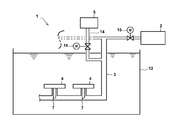
- FIG. 1 It is a schematic diagram of the air diffusion apparatus which concerns on Embodiment 1 of this invention. It is a partial cross section figure of the internal intubation which concerns on Embodiment 1 of this invention. It is a figure which shows the one aspect
- FIG. 9 is an end view in the longitudinal section of FIG. 8. It is an enlarged view which expands and shows a part of FIG.
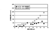
- FIG. 9 is a schematic diagram of the air diffusion apparatus which concerns on Embodiment 4 of this invention. It is explanatory drawing explaining the effect of the water blow in the Example of this invention, Comprising: It is a graph which shows a time-dependent change of the pressure loss increase amount.
- Air diffuser (Embodiment 1) DESCRIPTION OF SYMBOLS 2 Gas supply means 3 Air supply piping for aeration 4 Air diffuser plate 4a Air diffusion surface 5 Blow water supply means 7 Inner intubation 7a Valve seat 8 Suction surface 9 Air vent 10 Fixing member 11 Mounting bracket 12 Aeration tank 14 Blow water Supply pipe 15, 16 On-off valve 17 Slit 19 Check valve 21 Air diffuser (Embodiment 4) 23 Ventilation pipe 23a Ventilation opening 25 Open / close valve 27 Control means ⁇ Inclination angle
- FIG. 1 is a schematic diagram illustrating an air diffuser according to the first embodiment.
- a diffuser 1 according to Embodiment 1 includes a gas supply unit 2 that supplies a gas such as air, and an air supply pipe 3 (header) that guides air supplied from the gas supply unit 2 to a diffusion plate 4. Tube), an air diffuser plate 4 that receives supply of air from the air diffuser supply pipe 3 and discharges fine bubbles, and an upper end that is in communication with the air diffuser plate 4 and a lower end that is in the air diffuser air supply pipe 3.
- An internally inserted tube 7 and blow water supply means 5 for supplying blow water to the air supply pipe 3 for diffusion through a blow water supply tube 14 are provided.
- An open / close valve 15 is provided in the air supply pipe 3 for diffusion, and an open / close valve 16 is provided in the blow water supply pipe 14.
- the main configuration of the air diffuser 1 will be described in detail.
- the diffuser plate 4 may be any form of diffuser plate such as a membrane type or a thin metal plate type.
- a thin metal plate having slit-like fine holes formed by machining is used.
- the air supplied from the gas supply means 2 is supplied to the diffuser plate 4 from the diffuser air supply pipe 3 through the inner tube 7, and from a plurality of fine holes scattered on the diffuser surface 4 a of the diffuser plate 4. Released.
- the inner tube 7 has an upper end communicating with the diffuser plate 4, and a lower end inserted into the diffuser air supply pipe 3.
- the blow water supplied to the diffuser air supply pipe 3 is discharged from the diffuser plate 4. It is for making it happen. Therefore, the intubation tube 7 corresponds to the discharge means of the present invention.
- the air diffuser 1 according to the first embodiment since the inner intubation pipe 7 is provided, the water in the air diffuser air supply pipe 3 is diffused even if the air diffuser air supply pipe 3 is not filled with water. Can be supplied to the air diffusion surface 4a.
- the diffuser air supply pipe 3 As described above. After washing, a means for draining full water is required. If there is no means for draining water, water will remain in the air supply piping to which the air diffuser plate 4 is attached, and the passage through which air will be diffused will become narrower. Will not be able to perform a diffuse operation.
- the water supplied to the air supply pipe 3 is provided without providing a means for removing the water supplied to the air supply pipe 3. Can be discharged from the diffuser plate 4, which is convenient.
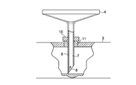
- FIG. 2 is a partial cross-sectional view showing an example of the internal intubation 7.
- the upper end of the inner intubation tube 7 communicates with the diffuser plate 4, and the lower end is inserted into the diffuser air supply pipe 3.
- the lower end part of the inner intubation 7 becomes the inclined suction surface 8, and has the vent hole 9 in the tube wall.
- the vent hole 9 provided in the tube wall of the inner tube 7 is not essential and the vent hole 9 may be omitted.
- the mode of pumping blow water to the intubation tube 7 differs depending on whether or not there are pores 9.
- the internal intubation 7 has a function as a supply path for supplying air for diffusing to the diffusing plate 4, and when supplying air to the diffusing plate 4, an air supply pipe for diffusing 3 has a function of discharging the water supplied to 3 from the diffuser plate 4.
- the internal intubation 7 may be formed integrally with the air supply pipe 3 for air diffusion or may be a separate member that can be attached to and detached from the air supply pipe 3 for air diffusion. When it is set as another member which can be attached or detached, the inner intubation 7 can be inserted and fixed to the insertion port previously provided in the air supply piping 3 for aeration.
- the fixing tightening member 10 is welded to the side surface of the inner intubation tube 7 in advance, and the attachment member 11 is previously welded to the side of the air supply piping for diffusion, thereby fixing the fastening member to be welded to the side surface of the inner tube 7.
- the member 10 can be screwed into the attachment member 11 and fixed to the air supply pipe 3 for diffusing.
- the diffuser plate 4 can be formed integrally with the inner intubation tube 7 or can be attached to and detached from the inner intubation tube 7.
- the lower end portion of the inner intubation 7 becomes a suction surface 8 for sucking water supplied to the air supply pipe 3 for aeration.
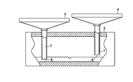
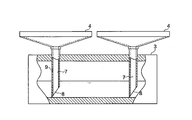
- a plurality of diffuser plates 4 are installed in the diffuser supply pipe 3, but the diffuser supply pipe 3 is not necessarily installed horizontally. Therefore, the lower end of each intubation 7 of the plurality of diffuser plates 4 is not necessarily arranged at the same height with respect to the water surface of the water supplied to the diffuser air supply pipe 3. In such a case, as shown in FIG. 3, when the suction surface 8 at the lower end of the intubation tube 7 is not inclined, the lower end is in contact with the water surface, or the water surface as shown in the left diagram of FIG.
- the vent hole 9 can have a circular shape with a diameter of 1 mm to 10 mm, preferably 2 mm to 7 mm.
- the position of the vent hole 9 is not particularly limited and can be set to an arbitrary position.
- an intubation tube having a total length of 200 mm and an inner diameter of 13 mm is mounted in an air supply pipe for air diffusion with an inner diameter of 80 mm, and the lower end of the inner tube is in contact with the inner bottom of the air supply pipe for air diffusion, It can be provided at a position of 10 mm to 75 mm, preferably 30 to 70 mm from the lower end of the intubation tube.
- the position of the vent hole 9 may be on the front side or the back side with respect to the direction of water blow and gas flow.
- the lower end of the inclined suction surface 8 is positioned in the vicinity of the inner bottom of the air supply pipe 3 for diffusing, so that even if the water level is low, the blow water can be surely sucked into the inner tube 7.
- the lower end of the inclined suction surface 8 is preferably 0 to 10 mm above the inner bottom of the air supply pipe 3 for air diffusion.
- the inclination angle ⁇ of the inclined suction surface 8 with respect to the tube axis direction of the inner tube 7 is not particularly limited. However, since the inner tube 7 is also an air supply path, air can be sufficiently supplied into the tube 7. It is preferable to set the tilt angle ⁇ to a certain value.
- the inclination angle ⁇ is, for example, 10 to 85 degrees, preferably 30 to 80 degrees.
- the blow water supply means 5 is a device for supplying blow water to the air supply pipe 3 for air diffusion via the blow water supply pipe 14, for overcoming the air pressure of the air supply pipe 3 for air diffusion.
- the air supply pipe 3 can be supplied.
- the blow water supply means 5 there is, for example, a water storage tank provided with a water pump.
- the blow water supplied from the blow water supply means 5 flows into the diffuser air supply pipe 3 through the blow water supply pipe 14, and enters the diffuser plate 4 from the diffuser air supply pipe 3 through the inner tube 7. Water is sent and discharged from a plurality of fine holes scattered on the air diffusion surface 4a of the air diffusion plate 4 in the same manner as air.
- a device for increasing the pressure in the air diffuser pipe is provided separately so that the pressure in the air diffuser air supply pipe 3 is increased after the blow water is supplied. It may be.
- a normal air diffuser is operated by opening the on-off valve 15 and closing the on-off valve 16. Further, at the time of the blow operation in which the air diffuser plate 4 is blown with water, the on-off valve 16 is opened and the blow water is supplied to the air diffuser supply pipe 3 so that the air diffused and the blow water are passed through the inner tube 7. And supply to the diffuser plate 4.
- the air diffuser 1 of the present invention periodically supplies blow water from the blow water supply means 5 to the air diffuser plate 4 so that the fine holes of the air diffuser plate 4 are not pulled up on the water surface.
- the biofilm attached to can be removed.
- blow water is supplied in the air supply piping 3 for aeration every several hours to several days.
- the air diffuser 1 includes the intubation tube 7 and regularly supplies blow water while supplying air for air diffusion, and adheres to the air diffuser holes of the air diffuser plate 4.
- the aeration apparatus 1 can be continuously operated while removing the biofilm with blow water.
- the quality of blow water is not particularly limited.
- the use of blow water containing a component having an effect of killing the microorganisms of the biofilm is effective for the growth of the biofilm microorganisms. Can be suppressed.
- the components of the biofilm that have the effect of killing microorganisms are contained.
- antibacterial substances or oxidizing substances more specifically, sodium hypochlorite, reverse soap, acids, alkalis, ozone, Or chlorine dioxide, an alkali metal carbonate, etc. are contained.
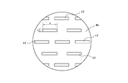
- FIG. 6 is a plan view of the diffuser plate 4 according to the second embodiment
- FIG. 7 is an enlarged view showing an A portion surrounded by a circle in FIG.
- the diffuser plate 4 is provided with a number of rectangular slits 17.
- a is 0.1 mm. -1.5 mm and b are set to be 0.03 mm to 0.15 mm.
- the reason why the lengths of the short side and the long side of the slit 17 are set in this way is as follows.
- the obstruction inhibiting effect of suppressing the obstruction of the slit 17 by removing the biofilm attached to the slit 17 with blow water is short of the slit 17. It is governed by the length of the side, and the longer the length of the short side, the higher the occlusion suppression effect.
- the length of the short side of the slit 17 is increased, the bubble diameter is increased and the oxygen transfer efficiency is lowered. Therefore, the length of the short side of the slit 17 provided on the air diffusing surface 4a of the air diffusing plate 4 is required to have a high blocking suppression effect and a high oxygen transfer efficiency.
- the length of the short side of the slit for obtaining a high oxygen transfer efficiency (25% or more) and suppressing the increase in pressure loss due to blockage (the amount of increase in pressure loss after 100 days of ventilation is 100 mmAq or less) will be described later.
- the length of the short side should be 0.03 mm to 0.15 mm.
- the length of the long side of the slit 17 is set to 0.1 mm to 1.5 mm as a range in which the oxygen transfer efficiency is adversely affected if it is too long.
- the minute holes formed in the diffuser plate 4 are rectangular slits 17 and the length of the short side is set to 0.03 mm to 0.15 mm. The effect of preventing clogging is high, and high oxygen transfer efficiency can be realized.
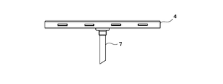
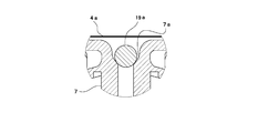
- FIG. 8 to 10 are explanatory views of the diffuser plate 4 according to the third embodiment, in which FIG. 8 is a front view, FIG. 9 is an end view of the longitudinal section of FIG. 8, and FIG. It is an enlarged view of the B section circled.
- a thin metal plate with slit-like fine holes is used as the air diffusion surface 4a having the fine holes used for the air diffusion plate 4.
- a check valve 19 is provided between the intubation tube 7 and the air diffusion surface 4 a of the air diffusion plate 4. It is what I did.
- the check valve 19 is configured such that a valve seat 7a is formed on the inner surface of the upper end of the inner tube 7 and a valve body 19a made of a spherical body is disposed on the valve seat 7a. With such a configuration, when air for blowing or blown water is supplied to the intubation tube 7, the valve body 19a moves upward and does not interfere with the supply of air or blown water. When the supply of water is stopped, the valve body 19a is seated on the valve seat 7a to prevent the backflow of sewage to the inner intubation 7 side.
- the open / close valve 15 is opened and the open / close valve 16 is closed.
- the valve body 19a does not float from the valve seat 7a and does not hinder the passage of air.
- the valve body 19a is seated on the valve seat 7a to prevent the backflow of sewage.
- the on-off valve 16 is opened and the blow water is supplied to the air diffuser supply pipe 3 so that the air diffused and the blow water are passed through the inner tube 7. And supply to the diffuser plate 4. Also in this case, the valve body 19a does not float from the valve seat 7a and obstruct the passage of the blow water as in the case of the air diffusion operation.
- the check valve 19 is provided in the present embodiment, even when the operation of the gas supply means 2 is stopped due to a power failure or management operation, sewage or activated sludge is scattered.
- the air diffuser 4 can be prevented from being clogged due to the backflowed sewage or the like without flowing backward to the inside of the air plate 4.
- valve body 19a of the check valve 19 an example in which a spherical body is used as an example of the valve body 19a of the check valve 19 is shown.
- the present invention is not limited to this, and for example, the valve body has a disk shape. It may be a thing.
- the valve body 19a since the gap between the air diffusion surface 4a and the valve seat 7a is set to be narrow, the valve body 19a can be provided without providing a frame that restricts the movement range of the valve body 19a. While moving up and down while maintaining a predetermined range, if the gap between the air diffusion surface 4a and the valve seat 7a is wide, a frame-like body that restricts the movement range of the valve body 19a may be provided. .
- FIG. 11 is a schematic diagram showing an air diffuser according to the fourth embodiment.
- the same parts as those in FIG. 1 are denoted by the same reference numerals.
- the injected blow water is close to If it is sucked up only in a certain intubation, or if the air supply pipe 3 for aeration to which the diffuser plate 4 is attached has a height, it flows to a low position and is sucked up only from the intubation 7 in a low position.
- the fourth embodiment an apparatus and a method are provided for cleaning all the diffuser plates 4 evenly while continuing to blow air to the diffuser supply pipe 3 in the diffused operation state. is there.
- one end side is connected to the aeration air supply pipe 3 and the other end side is immersed in the aeration tank 12 to diffuse.
- Opening / closing valve 25 for adjusting the pressure in the air supply pipe 3, the opening / closing valve 25 provided in the discharging pipe 23, and the opening / closing control of the opening / closing valve 16 provided in the opening / closing valve 25 and blow water supply pipe 14.
- a control means 27 for controlling the operation of the blow water supply means 5.
- the air discharge pipe 23 has one end connected to the air supply pipe 3 for aeration and the other end is immersed in the aeration tank 12 to adjust the pressure in the air supply pipe 3 for air diffusion.
- An opening / closing valve 25 is provided in the middle of the discharge pipe 23, and is opened / closed by a control signal from the control means 27.
- An air outlet 23a is provided at the end of the air discharge pipe 23 immersed in the aeration tank 12, and when the on-off valve 25 is opened, the pressure air in the air supply pipe 3 for aeration is released from the air outlet 23a. Is done. As shown in FIG. 11, the position of the air outlet 23 a is set to be a distance of H mm downward from the position of the diffuser plate 4.
- HmmAq is equal to or lower than the pumping pressure required to pump the water in the air supply pipe 3 to the inner intubation 7, even if blow water is supplied to the air supply pipe 3 for air diffusion, The supplied blow water is not sucked into the inner intubation 7 but is stored in the air supply piping 3 for aeration.
- the pumping pressure is in the range of 100 mm to 600 mmAq. Therefore, Hmm is set to be greater than 0 and in the range of 100 mm to 600 mm or less.
- the air diffuser 21 of the fourth embodiment configured as described above.
- the on-off valve 25 and the on-off valve 16 are closed for operation.
- the separately controlled gas supply device 2 is operated and the on-off valve 15 is opened, so that the pressurized air in the air supply piping 3 is sent to the air diffusion plate 4 and is diffused.
- the pressurized air in the air supply pipe 3 for air diffusion is released from the air outlet 23a of the air outlet pipe 23, and without changing the state of the separately controlled gas supply means 2 and the on-off valve 15,
- the pressure in the air supply pipe 3 becomes water pressure + HmmAq.
- the operation of the blow water supply means 5 is started, and the on-off valve 16 provided in the blow water supply pipe 14 is opened. Thereby, the blow water flows into the air supply pipe 3 for air diffusion through the blow water supply pipe 14.
- the pressure in the air supply pipe 3 for air diffusion is water pressure + HmmAq
- the blow water is not sucked into the inner intubation 7 and the air supply pipe for air diffusion to which the air diffusion plate 4 is attached. It is distributed in 3 and stored.
- the on-off valve 16 is closed to stop the supply of blow water.
- the on-off valve 25 is closed to stop the air discharge, the pressure in the air supply piping 3 increases, and when this pressure exceeds the water pressure + pumping pressure, the pressure is stored in the air supply piping 3.
- the blown water is sucked into the intubation tubes 7 of all the diffuser plates 4 and discharged from the diffuser holes of the diffuser plates 4, thereby cleaning the diffuser plates 4.
- the suction surface 8 of the inner intubation pipe 7 extends to the lower surface position of the air supply pipe 3 for air diffusion, almost all of the blow water stored in the air supply pipe 3 for air diffusion is discharged. Thereafter, normal aeration operation is continued. Even when the air supply pipe 3 for air diffusion is not installed horizontally and the lower end position of the intubation tube 7 varies with respect to the horizontal, the pumping during the supply of blow water is stopped as described above, and the variation is reduced.
- the blow water can be supplied to all the diffuser plates 4 without a predetermined amount or more.
- the discharge pipe 23 is used as a pressure adjusting means for adjusting the pressure in the air supply pipe 3 to a predetermined pressure.
- the pressure in the air supply pipe 3 can be adjusted to a predetermined pressure.
- the blow water can be stored in the air supply piping 3 for the aeration without backflow of the sewage in the aeration tank from the fine holes of the air diffusion surface 4a of the air diffusion plate 4, and all the air diffusion plates 4 can be stored. Can be washed evenly.
- the air discharge pipe 23 has been described as adjusting the pressure in the air supply pipe. However, it may be other than the air discharge pipe 23, for example, attached to the air supply pipe 3 for air diffusion. It may be a pressure adjusting valve for adjusting the pressure in the supply air pipe 3. As yet another method, pressure adjustment by adjusting the supply air amount of the gas supply device 2 and / or adjusting the opening of the on-off valve 15 may be used. The control of the gas supply device 2 and the on-off valve 15 in this case may be performed by the control means 27.
- Air diffuser material SUS316L Hole shape: length 1.45mm, short side (width) 0.04mm Opening ratio: about 0.5% Ventilation rate: 30m3 / m2 / hr
- Blow water Sodium hypochlorite solution (concentration: 100 ppm)
- Blow water volume 500 ml / time
- Water blow frequency 1 time / day An example in which no water blow was performed was used as a comparative example.
- the graph of FIG. 12 shows the change over time in the amount of increase in pressure loss (mmAq) in the example (Example) with and without water blow (Comparative Example).
- Air diffuser plate material SUS316L Long slit length: 0.5mm Ventilation rate: 30m 3 / m 2 / hr
- Blow water Sodium hypochlorite solution (concentration: 20 ppm)
- Blow water volume 500ml / time
- Water blow frequency 2 times / day
- Table 1 shows the oxygen transfer efficiency (the initial stage of the start of the diffuser) and the pressure loss increase after 100 days from the start of the diffuser.
- the length of the short side of the slit is set in the range of 0.08 mm to 0.12 mm, an extremely high oxygen transfer efficiency of 30% or more can be obtained, and the pressure loss increase after 100 days is 70 mmAq or less.
- the removal of the occlusive substance by the can be performed more effectively, which is preferable.
Landscapes
- Chemical & Material Sciences (AREA)
- Chemical Kinetics & Catalysis (AREA)
- Life Sciences & Earth Sciences (AREA)
- Biodiversity & Conservation Biology (AREA)
- Microbiology (AREA)
- Hydrology & Water Resources (AREA)
- Engineering & Computer Science (AREA)
- Environmental & Geological Engineering (AREA)
- Water Supply & Treatment (AREA)
- Organic Chemistry (AREA)
- Aeration Devices For Treatment Of Activated Polluted Sludge (AREA)
Abstract
Priority Applications (3)
| Application Number | Priority Date | Filing Date | Title |
|---|---|---|---|
| HK11101550.7A HK1147241B (en) | 2007-12-27 | 2008-12-25 | Diffuser apparatus, and diffuser apparatus running method |
| EP08867779.4A EP2226294B1 (fr) | 2007-12-27 | 2008-12-25 | Appareil diffuseur et procédé de fonctionnement de l'appareil diffuseur |
| US12/734,866 US8505882B2 (en) | 2007-12-27 | 2008-12-25 | Diffuser apparatus, and diffuser apparatus running method |
Applications Claiming Priority (4)
| Application Number | Priority Date | Filing Date | Title |
|---|---|---|---|
| JP2007-338380 | 2007-12-27 | ||
| JP2007338380 | 2007-12-27 | ||
| JP2008131043A JP5262287B2 (ja) | 2007-12-27 | 2008-05-19 | 散気装置および散気装置の運転方法 |
| JP2008-131043 | 2008-05-19 |
Publications (1)
| Publication Number | Publication Date |
|---|---|
| WO2009084576A1 true WO2009084576A1 (fr) | 2009-07-09 |
Family
ID=40824290
Family Applications (1)
| Application Number | Title | Priority Date | Filing Date |
|---|---|---|---|
| PCT/JP2008/073562 Ceased WO2009084576A1 (fr) | 2007-12-27 | 2008-12-25 | Appareil diffuseur et procédé de fonctionnement de l'appareil diffuseur |
Country Status (5)
| Country | Link |
|---|---|
| US (1) | US8505882B2 (fr) |
| EP (1) | EP2226294B1 (fr) |
| JP (1) | JP5262287B2 (fr) |
| MY (1) | MY155187A (fr) |
| WO (1) | WO2009084576A1 (fr) |
Cited By (1)
| Publication number | Priority date | Publication date | Assignee | Title |
|---|---|---|---|---|
| JP6201014B1 (ja) * | 2016-07-19 | 2017-09-20 | 月島機械株式会社 | 散気システム |
Families Citing this family (10)
| Publication number | Priority date | Publication date | Assignee | Title |
|---|---|---|---|---|
| US8657268B2 (en) * | 2007-02-28 | 2014-02-25 | Gregory P. Smiltneek | Methods and apparatus for wastewater treatment |
| JP5062138B2 (ja) * | 2007-12-27 | 2012-10-31 | Jfeエンジニアリング株式会社 | 散気装置の洗浄方法 |
| JP5551010B2 (ja) * | 2010-07-26 | 2014-07-16 | メタウォーター株式会社 | 散気システム |
| JP5535817B2 (ja) * | 2010-08-06 | 2014-07-02 | 三菱重工業株式会社 | エアレーション装置及びこれを備えた海水排煙脱硫装置、エアレーション装置の加湿方法 |
| JP5730377B2 (ja) * | 2013-11-13 | 2015-06-10 | 株式会社クボタ | 散気管及び散気管の洗浄方法 |
| EP3110538A2 (fr) * | 2014-02-28 | 2017-01-04 | Martin Stachowske | Dispositif fixe et mobile pour l'incorporation énergétiquement optimisée d'un fluide dans un fluide par une insertion contrôlée de bulles ou de gouttes individuelles d'un gaz, d'un mélange gazeux ou d'un fluide |
| US20190337827A1 (en) * | 2016-04-15 | 2019-11-07 | Somerset Environmental Solutions Inc. | Apparatus and Method for Aerating Wastewater |
| CN107606376B (zh) * | 2017-10-18 | 2018-05-11 | 河海大学 | 一种曝气管路冷凝水或泄漏水自动排水装置 |
| US11155482B2 (en) | 2018-04-04 | 2021-10-26 | Somerset Environmental Solutions Inc. | Apparatus and method for aerating wastewater |
| DE102021119249A1 (de) | 2021-07-26 | 2023-01-26 | Mann+Hummel Life Sciences & Environment Holding Singapore Pte. Ltd. | Belüftungsvorrichtung, Membranbioreaktor und Verfahren |
Citations (12)
| Publication number | Priority date | Publication date | Assignee | Title |
|---|---|---|---|---|
| JPS5758497U (fr) * | 1980-09-25 | 1982-04-06 | ||
| JPS58141796U (ja) * | 1982-03-17 | 1983-09-24 | 株式会社三井三池製作所 | ばつ気槽散気装置の目詰まり防止装置 |
| JPS6436099U (fr) * | 1987-08-25 | 1989-03-06 | ||
| JPH1099663A (ja) * | 1996-09-27 | 1998-04-21 | Mitsubishi Rayon Co Ltd | 膜処理装置 |
| JP2000051885A (ja) * | 1998-08-13 | 2000-02-22 | Mitsubishi Rayon Co Ltd | 活性汚泥処理装置 |
| JP2000343095A (ja) * | 1999-06-02 | 2000-12-12 | Mitsubishi Rayon Co Ltd | 活性汚泥処理装置 |
| JP2003320388A (ja) | 2002-05-07 | 2003-11-11 | Ngk Insulators Ltd | メンブレン散気装置 |
| JP2004033889A (ja) * | 2002-07-02 | 2004-02-05 | Sumitomo Heavy Ind Ltd | 散気方法及び散気システム |
| JP2004305886A (ja) * | 2003-04-07 | 2004-11-04 | Kubota Corp | 散気装置 |
| JP2004313938A (ja) | 2003-04-16 | 2004-11-11 | Kobelco Eco-Solutions Co Ltd | 散気装置の目詰まり防止運転方法 |
| JP2006061817A (ja) | 2004-08-26 | 2006-03-09 | Jfe Engineering Kk | 散気装置 |
| JP2006187728A (ja) * | 2005-01-06 | 2006-07-20 | Hitachi Kiden Kogyo Ltd | 散気装置 |
Family Cites Families (11)
| Publication number | Priority date | Publication date | Assignee | Title |
|---|---|---|---|---|
| US2689714A (en) * | 1950-08-11 | 1954-09-21 | Richard C French | Method and apparatus for preventing the clogging of diffuser media |
| US4639314A (en) * | 1985-01-18 | 1987-01-27 | Tyer Robert R | Fine bubble diffuser and diffuser system having filtered blow-down tube |
| US5051193A (en) * | 1986-03-06 | 1991-09-24 | Aeration Engineering Resources Corporation | Waste water treatment process |
| JPS62258729A (ja) * | 1986-05-02 | 1987-11-11 | Mitsubishi Heavy Ind Ltd | 通気タンク用気体吹込方法 |
| JPH0248025Y2 (fr) * | 1986-10-06 | 1990-12-17 | ||
| US5336230A (en) * | 1992-11-04 | 1994-08-09 | Charles S. Taylor | Endoscopic suture tying method |
| US5378355A (en) * | 1992-12-04 | 1995-01-03 | Water Pollution Control Corporation | Direct delivery in-situ diffuser cleaning |
| US8852438B2 (en) * | 1995-08-11 | 2014-10-07 | Zenon Technology Partnership | Membrane filtration module with adjustable header spacing |
| US6013120A (en) * | 1996-08-14 | 2000-01-11 | Mcdermott Technology, Inc. | Apparatus for air sparged slurry tanks |
| JP3853657B2 (ja) * | 2000-03-27 | 2006-12-06 | 株式会社荏原製作所 | 排水の処理方法及び装置 |
| AT411359B (de) * | 2002-01-17 | 2003-12-29 | Frey Wilhelm | Reinigungsverfahren und reinigungsflüssigkeit für belüfterkörper |
-
2008
- 2008-05-19 JP JP2008131043A patent/JP5262287B2/ja not_active Expired - Fee Related
- 2008-12-25 MY MYPI2010002767A patent/MY155187A/en unknown
- 2008-12-25 EP EP08867779.4A patent/EP2226294B1/fr not_active Not-in-force
- 2008-12-25 US US12/734,866 patent/US8505882B2/en not_active Expired - Fee Related
- 2008-12-25 WO PCT/JP2008/073562 patent/WO2009084576A1/fr not_active Ceased
Patent Citations (12)
| Publication number | Priority date | Publication date | Assignee | Title |
|---|---|---|---|---|
| JPS5758497U (fr) * | 1980-09-25 | 1982-04-06 | ||
| JPS58141796U (ja) * | 1982-03-17 | 1983-09-24 | 株式会社三井三池製作所 | ばつ気槽散気装置の目詰まり防止装置 |
| JPS6436099U (fr) * | 1987-08-25 | 1989-03-06 | ||
| JPH1099663A (ja) * | 1996-09-27 | 1998-04-21 | Mitsubishi Rayon Co Ltd | 膜処理装置 |
| JP2000051885A (ja) * | 1998-08-13 | 2000-02-22 | Mitsubishi Rayon Co Ltd | 活性汚泥処理装置 |
| JP2000343095A (ja) * | 1999-06-02 | 2000-12-12 | Mitsubishi Rayon Co Ltd | 活性汚泥処理装置 |
| JP2003320388A (ja) | 2002-05-07 | 2003-11-11 | Ngk Insulators Ltd | メンブレン散気装置 |
| JP2004033889A (ja) * | 2002-07-02 | 2004-02-05 | Sumitomo Heavy Ind Ltd | 散気方法及び散気システム |
| JP2004305886A (ja) * | 2003-04-07 | 2004-11-04 | Kubota Corp | 散気装置 |
| JP2004313938A (ja) | 2003-04-16 | 2004-11-11 | Kobelco Eco-Solutions Co Ltd | 散気装置の目詰まり防止運転方法 |
| JP2006061817A (ja) | 2004-08-26 | 2006-03-09 | Jfe Engineering Kk | 散気装置 |
| JP2006187728A (ja) * | 2005-01-06 | 2006-07-20 | Hitachi Kiden Kogyo Ltd | 散気装置 |
Non-Patent Citations (1)
| Title |
|---|
| See also references of EP2226294A4 |
Cited By (2)
| Publication number | Priority date | Publication date | Assignee | Title |
|---|---|---|---|---|
| JP6201014B1 (ja) * | 2016-07-19 | 2017-09-20 | 月島機械株式会社 | 散気システム |
| JP2018012051A (ja) * | 2016-07-19 | 2018-01-25 | 月島機械株式会社 | 散気システム |
Also Published As
| Publication number | Publication date |
|---|---|
| US20100300965A1 (en) | 2010-12-02 |
| EP2226294A1 (fr) | 2010-09-08 |
| US8505882B2 (en) | 2013-08-13 |
| JP2009172570A (ja) | 2009-08-06 |
| HK1147241A1 (en) | 2011-08-05 |
| EP2226294B1 (fr) | 2015-10-14 |
| JP5262287B2 (ja) | 2013-08-14 |
| MY155187A (en) | 2015-09-15 |
| EP2226294A4 (fr) | 2013-03-27 |
Similar Documents
| Publication | Publication Date | Title |
|---|---|---|
| JP5062140B2 (ja) | 散気装置の運転方法および散気装置 | |
| US8505882B2 (en) | Diffuser apparatus, and diffuser apparatus running method | |
| KR20150053981A (ko) | 산기 장치와 그 운전 방법, 및 수처리 장치 | |
| JP2018108585A (ja) | 散気装置、散気方法、及び水処理装置 | |
| JPH11244674A (ja) | 浸漬型膜分離装置 | |
| KR20110058989A (ko) | 하이브리드형 산기관 시스템 | |
| CN103459332B (zh) | 散气装置的运行方法 | |
| JP2014172014A (ja) | 膜分離装置および膜分離方法 | |
| JP5235632B2 (ja) | 曝気用散気装置および散気方法 | |
| JP2008253901A (ja) | 固液分離装置及びこの固液分離装置を有する水処理装置 | |
| JP2002273467A (ja) | 散気装置及びこれを用いた生物処理槽 | |
| JP2006205119A (ja) | 浸漬型膜分離装置の使用方法および浸漬型膜分離装置 | |
| HK1147241B (en) | Diffuser apparatus, and diffuser apparatus running method | |
| KR101162615B1 (ko) | 침지형 모듈의 산기관 구조 | |
| KR20110058977A (ko) | 산기관 | |
| JP3659672B2 (ja) | 循環水路型曝気槽におけるスカムの除去装置 | |
| JP2014195766A (ja) | 散気装置および水処理装置 | |
| JP2019098239A (ja) | 散気装置、散気方法、及び水処理装置 | |
| JP2019111461A (ja) | 散気装置、散気方法、及び水処理装置 | |
| JP2011218265A (ja) | 散気装置 | |
| KR20050113540A (ko) | 소포용 다단형 분사노즐 | |
| JP2017209626A (ja) | 散気方法および散気装置 | |
| JP2012187522A (ja) | 散気装置 |
Legal Events
| Date | Code | Title | Description |
|---|---|---|---|
| 121 | Ep: the epo has been informed by wipo that ep was designated in this application |
Ref document number: 08867779 Country of ref document: EP Kind code of ref document: A1 |
|
| WWE | Wipo information: entry into national phase |
Ref document number: 12010501113 Country of ref document: PH |
|
| WWE | Wipo information: entry into national phase |
Ref document number: 2008867779 Country of ref document: EP |
|
| WWE | Wipo information: entry into national phase |
Ref document number: 12734866 Country of ref document: US |
|
| NENP | Non-entry into the national phase |
Ref country code: DE |
|
| WWE | Wipo information: entry into national phase |
Ref document number: PI 2010002767 Country of ref document: MY |