WO2009087750A1 - フィルタ洗浄装置及びフィルタ洗浄方法 - Google Patents
フィルタ洗浄装置及びフィルタ洗浄方法 Download PDFInfo
- Publication number
- WO2009087750A1 WO2009087750A1 PCT/JP2008/050005 JP2008050005W WO2009087750A1 WO 2009087750 A1 WO2009087750 A1 WO 2009087750A1 JP 2008050005 W JP2008050005 W JP 2008050005W WO 2009087750 A1 WO2009087750 A1 WO 2009087750A1
- Authority
- WO
- WIPO (PCT)
- Prior art keywords
- filter
- cleaning
- processing container
- bubble flow
- liquid
- Prior art date
- Legal status (The legal status is an assumption and is not a legal conclusion. Google has not performed a legal analysis and makes no representation as to the accuracy of the status listed.)
- Ceased
Links
Images
Classifications
-
- B—PERFORMING OPERATIONS; TRANSPORTING
- B08—CLEANING
- B08B—CLEANING IN GENERAL; PREVENTION OF FOULING IN GENERAL
- B08B3/00—Cleaning by methods involving the use or presence of liquid or steam
- B08B3/04—Cleaning involving contact with liquid
- B08B3/10—Cleaning involving contact with liquid with additional treatment of the liquid or of the object being cleaned, e.g. by heat, by electricity or by vibration
- B08B3/102—Cleaning involving contact with liquid with additional treatment of the liquid or of the object being cleaned, e.g. by heat, by electricity or by vibration with means for agitating the liquid
-
- B—PERFORMING OPERATIONS; TRANSPORTING
- B01—PHYSICAL OR CHEMICAL PROCESSES OR APPARATUS IN GENERAL
- B01D—SEPARATION
- B01D41/00—Regeneration of the filtering material or filter elements outside the filter for liquid or gaseous fluids
- B01D41/04—Regeneration of the filtering material or filter elements outside the filter for liquid or gaseous fluids of rigid self-supporting filtering material
-
- B—PERFORMING OPERATIONS; TRANSPORTING
- B08—CLEANING
- B08B—CLEANING IN GENERAL; PREVENTION OF FOULING IN GENERAL
- B08B3/00—Cleaning by methods involving the use or presence of liquid or steam
- B08B3/04—Cleaning involving contact with liquid
-
- B—PERFORMING OPERATIONS; TRANSPORTING
- B08—CLEANING
- B08B—CLEANING IN GENERAL; PREVENTION OF FOULING IN GENERAL
- B08B3/00—Cleaning by methods involving the use or presence of liquid or steam
- B08B3/04—Cleaning involving contact with liquid
- B08B3/10—Cleaning involving contact with liquid with additional treatment of the liquid or of the object being cleaned, e.g. by heat, by electricity or by vibration
Definitions
- the present invention relates to a cleaning technique for a filter mounted on a powder processing apparatus, and more particularly, to a cleaning process for a cartridge filter having a pleated structure.
- a granular material processing apparatus such as a fluidized bed granulation coating apparatus that performs processing such as granulation by fluidizing a fine substance by a gas flow is used.
- a gas is supplied for fluidizing the granular material, and a filter for separating the granular material from the exhaust gas is provided.
- the granular material fluidized by the gas flow is filtered by this filter, and only the gas is separated and discharged to the outside of the granular material processing apparatus.
- a filter cloth formed in a pleated shape is often used in order to increase the filtration area.
- the gas flow is hindered, the fluidization of the granular material is hindered, and the processing efficiency is lowered.
- the fine powder adhering to the filter medium is appropriately removed. The fine powder is removed by supplying pulsed air in the direction opposite to the fluidized gas flow.
- the powder adhering to the filter cannot be completely removed even by such a removal process, and the powder gradually accumulates to increase the air flow resistance. For this reason, when granulation or the like is performed, it is necessary to separately perform a filter cleaning process when the process is performed for a predetermined time or more.
- the fine powder adhering to the back of the pleat tends to aggregate.
- backwash air is difficult to pass through the back of the pleat, it is difficult to sufficiently remove even the fine powder in the back of the pleat.
- Patent Document 1 a wet cleaning method as in Patent Document 1 in which a filter is rotationally cleaned has been proposed.
- a pleated filter is rotatably installed and a cleaning liquid is sprayed from an oblique direction to the outer periphery thereof.
- the filter that has received the cleaning liquid rotates in the cleaning device, and the cleaning liquid is intensively and efficiently sprayed on the entire surface of the filter.
- the fine powder adhering to the back of the pleat is also discharged out of the filter by centrifugal force, and an efficient cleaning process is performed.
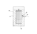
- a filter is placed vertically in a processing container (rotating shaft is arranged in a vertical direction), and a cleaning liquid or a bubble flow is jetted onto the filter from the lateral direction (horizontal direction).
- efficient cleaning processing may not be performed.
- FIG. 3 in the case of a system in which a filter 53 is placed vertically in a processing container 52 filled with a cleaning liquid 51 and a bubble flow etc. is jetted from the horizontal direction, a bubble flow etc. jetted from a nozzle 55 etc. rises in the atmospheric direction after injection. For this reason, the bubble flow 54 does not hit the filter 53 from the side, and the efficient cleaning process may not be performed only by the bubble flow.
- An object of the present invention is to provide a filter cleaning apparatus and a cleaning method capable of efficiently cleaning a cartridge filter used in a fluidized bed granulator or the like.
- the filter cleaning apparatus of the present invention is formed so as to be able to hold a cleaning liquid, and is capable of rotatably storing a filter used in a granular material processing apparatus in a state where the cleaning liquid is injected and held, and the processing container And a nozzle device that jets a bubble flow or a liquid containing bubbles to the filter immersed in the cleaning liquid and cleans the filter while rotating the filter in the cleaning liquid.
- the filter is disposed in the processing container so as to be rotatable about a substantially horizontal rotation axis, and the nozzle device is disposed below the filter.
- the filter is disposed so as to be rotatable about a substantially horizontal rotation axis, and the nozzle device is disposed below the filter, whereby the bubble flow ejected from the nozzle device or the liquid containing bubbles is obtained. Pressure that bubbles rise from water to the atmosphere is applied. For this reason, the filter is efficiently rotated by the synergistic effect of the jet pressure and the rising pressure of the bubble flow.
- a filter support member that rotatably supports a rotating shaft attached to the center of the filter, and a liquid containing bubble flow or bubbles from the lower side of the filter to the filter. You may provide the nozzle apparatus to inject.
- the filter may be a cartridge filter having a pleated structure, such as a cylindrical cartridge filter in which a filter cloth is formed into a pleated shape.
- the filter cleaning method of the present invention is a filter cleaning method for cleaning a filter used in a powder processing apparatus by storing it in a processing container storing a cleaning liquid, wherein the filter is substantially horizontal.
- a liquid containing a bubble flow or bubbles along a tangential direction with respect to the filter from a nozzle device installed rotatably around the axis of rotation in the processing vessel and below the filter in the processing vessel The filter is washed while rotating the filter with the bubble flow or the liquid containing bubbles.
- the filter may be a cartridge filter having a pleated structure.
- the filter is installed in the processing container so as to be rotatable about a substantially horizontal rotation axis, and a bubble flow or tangential direction from the nozzle device installed below the filter along the tangential direction to the filter.
- the filter is immersed in the processing container storing the cleaning liquid, and the cleaning process is performed while rotating the filter with the bubble flow or the liquid containing bubbles ejected from the nozzle device attached to the processing container.
- the filter cleaning device that implements the above, the filter is disposed so as to be rotatable about a substantially horizontal rotation axis, and the nozzle device is disposed below the filter.
- the pressure at which the bubbles rise into the atmosphere is applied, and the filter can be efficiently rotated by the synergistic effect of the jet pressure of the bubble flow and the rising pressure. For this reason, the energy which a bubble has can be used efficiently, and an efficient cleaning process is attained.
- the filter is immersed in the processing container storing the cleaning liquid, and the cleaning process is performed while the filter is rotated by the bubble flow or the liquid containing bubbles ejected from the nozzle device attached to the processing container.
- the filter is installed in the processing container so as to be rotatable about a substantially horizontal rotation axis, and bubbles are tangential to the filter from the nozzle device installed below the filter.
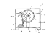
- FIG. 1 is an explanatory view showing the configuration of a filter cleaning apparatus according to an embodiment of the present invention, and is a cross-sectional view of the apparatus viewed from the side.
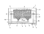
- FIG. 2 is a cross-sectional view of the filter cleaning device of FIG. 1 as viewed from the front.
- the filter cleaning apparatus 1 in FIG. 1 is a cartridge filter cleaning apparatus used in a powder processing apparatus such as a fluidized bed granulation coating apparatus, and is formed separately from the powder processing apparatus.
- the filter cleaning device 1 is a cleaning device dedicated to the cartridge filter, and the cartridge filter removed from the particle processing device is cleaned in the filter cleaning device 1.
- the filter cleaning device 1 includes a box-shaped processing container 2.
- the processing container 2 is filled with the cleaning liquid 10.
- the cartridge filter 3 (hereinafter abbreviated as “filter 3”) is immersed in the cleaning liquid 10, and cleaning is performed while being rotated by the bubble flow BF or the like.
- the processing container 2 is formed of acrylic resin so as to be transparent, and the inside state, that is, the filter cleaning state can be observed from the outside of the apparatus.
- a bottom plate 4 made of a metal such as stainless steel is attached to the lower portion of the processing container 2.
- Support legs 5 are attached to the bottom surface side of the bottom plate 4.
- the processing container 2 is installed on the floor surface by the support legs 5.
- the filter 3 is placed horizontally in a processing container 2 (a state where the rotation shaft is disposed in the horizontal direction).
- Filter support plates (filter support members) 6 a and 6 b are erected on the bottom plate 4 of the processing container 2.
- the filter 3 is rotatably attached to the upper ends of the filter support plates 6a and 6b.
- a rotary shaft 7 is attached to the filter 3 during the cleaning process.
- the rotary shaft 7 is rotatably supported by the filter support plates 6a and 6b. That is, the filter 3 is installed in the processing container 2 so as to be rotatable about a substantially horizontal rotation axis O.
- an air nozzle (nozzle device) 9 for supplying a bubble flow is disposed at the bottom of the processing vessel 2.
- An air supply pipe 9 is connected to the air nozzle 8. Compressed air is supplied to the air nozzle 8 from an external compressor (not shown) through the air supply pipe 9.
- two air nozzles 8 are arranged in the longitudinal direction of the apparatus.
- a drain 11 is attached to the lower surface side of the bottom plate 4. From the drain 11, the cleaning liquid 10 in the processing container 2 can be discharged out of the container.
- a bubble flow BF is jetted from the air nozzle 8 toward the upper filter 3.
- the bubble flow BF of the air nozzle 8 is jetted from the tangential direction to the filter 3, and the filter 3 rotates about the rotation shaft 7 by the bubble flow BF.
- the bubble flow BF ejected from the air nozzle 8 is subjected to pressure (buoyancy) that causes the bubbles to rise from the water to the atmosphere in addition to the ejection pressure.
- the filter 3 rotates efficiently by the synergistic effect of the ejection pressure + the rising pressure.
- the filter 3 is placed horizontally in the processing container 2, and the bubble flow BF is supplied to the filter 3 from below, so that the filter 3 is applied to the filter 3 while using the upward pressure increase of the bubbles.
- Rotational pressure can be applied from the side. For this reason, the energy which a bubble has can be utilized efficiently, and it becomes possible to rotate the filter 3 more favorably. Therefore, an efficient cleaning process is possible.
- the present invention is not limited to the above-described embodiments, and various modifications can be made without departing from the scope of the invention.
- an ultrasonic cleaner can be used in combination in order to further improve the cleaning effect.
- the number of air nozzles 8 is not limited to two, and can be changed as appropriate depending on the size of the filter 3.
- the liquid level S of the cleaning liquid 10 in the processing container 2 is lower than the upper end position of the filter 3, and the filter 3 is not completely submerged in the cleaning liquid 10. The position can be set as appropriate.
- the material of the processing container 2 is not limited to acrylic resin, and can be changed to metal such as stainless steel, FRP, or the like.
Landscapes
- Chemical & Material Sciences (AREA)
- Chemical Kinetics & Catalysis (AREA)
- Cleaning By Liquid Or Steam (AREA)
Abstract
Description
2 処理容器
3 カートリッジフィルタ
4 底板
5 支持脚
6a,6b フィルタ支持板(フィルタ支持部材)
7 回転軸
8 エアノズル(ノズル装置)
9 給気管
10 洗浄液
11 ドレイン
51 洗浄液
52 処理容器
53 フィルタ
54 気泡流等
55 ノズル
BF 気泡流
O 回転軸線
S 液面
例えば、図1のフィルタ洗浄装置1において、さらに洗浄効果を高めるため、超音波洗浄器を併用することも可能である。また、エアノズル8に代えて、バブリングジェットノズルを使用することも可能である。さらに、エアノズル8の個数は2個には限定されず、フィルタ3のサイズにより、適宜変更可能である。一方、図1,2では、処理容器2における洗浄液10の液面Sがフィルタ3の上端位置よりも低くなっており、フィルタ3が洗浄液10内に完全に没していないが、液面Sの位置は適宜設定可能である。加えて、処理容器2の材質もアクリル樹脂に限定されず、ステンレス等の金属やFRP等に変更することも可能である。
Claims (5)
- 洗浄液を保持可能に形成され、前記洗浄液が注入・保持された状態で、粉粒体処理装置に使用されるフィルタを回転自在に収容可能な処理容器と、
前記処理容器に取り付けられ、前記洗浄液中に浸漬された状態の前記フィルタに対し気泡流又は気泡を含む液体を噴射し、前記フィルタを前記洗浄液中にて回転させつつ洗浄するノズル装置とを有してなるフィルタ洗浄装置であって、
前記フィルタは、前記処理容器内に略水平な回転軸線を中心に回転自在に配置されると共に、前記ノズル装置は、前記フィルタの下方に配置されることを特徴とするフィルタ洗浄装置。 - 請求項1記載のフィルタ洗浄装置において、前記処理容器は、
前記処理容器内に設置され、前記フィルタの中心に取り付けられた回転軸を回転自在に支持するフィルタ支持部材と、
前記処理容器の底部に配置され、前記フィルタの下方から前記フィルタに対して気泡流又は気泡を含む液体を噴射するノズル装置とを有することを特徴とするフィルタ洗浄装置。 - 請求項1記載のフィルタ洗浄装置において、前記フィルタが、プリーツ状の構造を有するカートリッジフィルタであることを特徴とするフィルタ洗浄装置。
- 粉粒体処理装置にて使用されるフィルタを、洗浄液を貯留した処理容器内に収容して洗浄するフィルタ洗浄方法であって、
前記フィルタを、略水平な回転軸線を中心として、前記処理容器内に回転自在に設置し、
前記処理容器内の前記フィルタの下方に設置されたノズル装置から、前記フィルタに対し接線方向に沿って気泡流又は気泡を含む液体を噴射し、該気泡流又は気泡を含む液体によって前記フィルタを回転させつつ前記フィルタの洗浄を行うことを特徴とするフィルタ洗浄方法。 - 請求項4記載のフィルタ洗浄方法において、前記フィルタが、プリーツ状の構造を有するカートリッジフィルタであることを特徴とするフィルタ洗浄方法。
Priority Applications (3)
| Application Number | Priority Date | Filing Date | Title |
|---|---|---|---|
| PCT/JP2008/050005 WO2009087750A1 (ja) | 2008-01-04 | 2008-01-04 | フィルタ洗浄装置及びフィルタ洗浄方法 |
| US12/808,259 US20100258147A1 (en) | 2008-01-04 | 2008-01-04 | Filter cleaning apparatus and filter cleaning method |
| EP08702886.6A EP2233191A4 (en) | 2008-01-04 | 2008-01-04 | FILTER CLEANING DEVICE AND METHOD FOR CLEANING A FILTER |
Applications Claiming Priority (1)
| Application Number | Priority Date | Filing Date | Title |
|---|---|---|---|
| PCT/JP2008/050005 WO2009087750A1 (ja) | 2008-01-04 | 2008-01-04 | フィルタ洗浄装置及びフィルタ洗浄方法 |
Publications (1)
| Publication Number | Publication Date |
|---|---|
| WO2009087750A1 true WO2009087750A1 (ja) | 2009-07-16 |
Family
ID=40852875
Family Applications (1)
| Application Number | Title | Priority Date | Filing Date |
|---|---|---|---|
| PCT/JP2008/050005 Ceased WO2009087750A1 (ja) | 2008-01-04 | 2008-01-04 | フィルタ洗浄装置及びフィルタ洗浄方法 |
Country Status (3)
| Country | Link |
|---|---|
| US (1) | US20100258147A1 (ja) |
| EP (1) | EP2233191A4 (ja) |
| WO (1) | WO2009087750A1 (ja) |
Cited By (3)
| Publication number | Priority date | Publication date | Assignee | Title |
|---|---|---|---|---|
| CN102423763A (zh) * | 2011-10-20 | 2012-04-25 | 天脊煤化工集团股份有限公司 | 一种造粒机出料溜槽防结疤的方法及装置 |
| US20160198929A1 (en) * | 2008-10-23 | 2016-07-14 | Electrolux Home Products Corporation, N.V. | Dishwasher |
| CN116447858A (zh) * | 2023-03-16 | 2023-07-18 | 江苏赛隆环境工程有限公司 | 一种超大型环保高效节能烘干箱 |
Families Citing this family (10)
| Publication number | Priority date | Publication date | Assignee | Title |
|---|---|---|---|---|
| CA2735756A1 (en) * | 2011-03-31 | 2012-09-30 | Craig Hopf | Weed and trash screening apparatus for irrigation systems |
| CN102500566B (zh) * | 2011-09-22 | 2014-01-15 | 清华大学 | 适于危险环境使用的免维修泥浆洗涤器及其工作方法 |
| JP5589021B2 (ja) * | 2012-04-19 | 2014-09-10 | 株式会社栗本鐵工所 | フィルタ洗浄装置 |
| US9550139B2 (en) | 2014-03-04 | 2017-01-24 | Vincent James Madonia | Apparatus and system for cleaning a filter |
| US9808840B2 (en) * | 2014-10-15 | 2017-11-07 | Saudi Arabian Oil Company | Air filter ultrasonic cleaning systems and the methods of using the same |
| CN105617766B (zh) * | 2014-11-07 | 2017-09-01 | 中国石油天然气股份有限公司 | 一种篮式过滤网清洗机 |
| CN105999860A (zh) * | 2016-07-29 | 2016-10-12 | 江门市河正环保设备有限公司 | 一种水循环的滤芯清洗机 |
| CN105999861A (zh) * | 2016-07-29 | 2016-10-12 | 江门市河正环保设备有限公司 | 一种滤芯清洗机 |
| CN215585615U (zh) * | 2021-04-29 | 2022-01-21 | 宁德时代新能源科技股份有限公司 | 浆料过滤装置及涂布系统 |
| US12023615B1 (en) * | 2023-11-10 | 2024-07-02 | Filter Preaux, LLC | Cartridge filter cleaning system and method |
Citations (4)
| Publication number | Priority date | Publication date | Assignee | Title |
|---|---|---|---|---|
| JPH06262015A (ja) | 1992-05-26 | 1994-09-20 | Niro Aeromatic Ag | フィルタカートリッジの湿式洗浄法 |
| JPH10235168A (ja) | 1997-02-24 | 1998-09-08 | Mitsubishi Rayon Co Ltd | フィルターの洗浄方法 |
| JP2001232309A (ja) * | 2000-02-24 | 2001-08-28 | Kazuo Arai | 筒型エアフィルタの洗浄方法及び筒型エアフィルタ洗浄装置 |
| JP2004097936A (ja) | 2002-09-09 | 2004-04-02 | Me Technos Kk | フィルタ洗浄装置 |
Family Cites Families (5)
| Publication number | Priority date | Publication date | Assignee | Title |
|---|---|---|---|---|
| JPS57117305A (en) * | 1981-01-09 | 1982-07-21 | Hitachi Ltd | Regeneration of oil-separating element |
| JPS59195651A (ja) * | 1983-04-21 | 1984-11-06 | Nec Corp | ホトマスク洗浄装置 |
| JP3031402B2 (ja) * | 1993-11-29 | 2000-04-10 | 株式会社石垣 | 外圧式膜ろ過装置 |
| US20080006290A1 (en) * | 2006-07-10 | 2008-01-10 | Kuniaki Yamanaka | Fluidized bed apparatus and filter washing method for fluidized bed apparatus |
| JP5100358B2 (ja) * | 2007-04-13 | 2012-12-19 | フロイント産業株式会社 | フィルタ洗浄装置及びフィルタ洗浄方法 |
-
2008
- 2008-01-04 WO PCT/JP2008/050005 patent/WO2009087750A1/ja not_active Ceased
- 2008-01-04 US US12/808,259 patent/US20100258147A1/en not_active Abandoned
- 2008-01-04 EP EP08702886.6A patent/EP2233191A4/en not_active Withdrawn
Patent Citations (4)
| Publication number | Priority date | Publication date | Assignee | Title |
|---|---|---|---|---|
| JPH06262015A (ja) | 1992-05-26 | 1994-09-20 | Niro Aeromatic Ag | フィルタカートリッジの湿式洗浄法 |
| JPH10235168A (ja) | 1997-02-24 | 1998-09-08 | Mitsubishi Rayon Co Ltd | フィルターの洗浄方法 |
| JP2001232309A (ja) * | 2000-02-24 | 2001-08-28 | Kazuo Arai | 筒型エアフィルタの洗浄方法及び筒型エアフィルタ洗浄装置 |
| JP2004097936A (ja) | 2002-09-09 | 2004-04-02 | Me Technos Kk | フィルタ洗浄装置 |
Non-Patent Citations (1)
| Title |
|---|
| See also references of EP2233191A4 * |
Cited By (5)
| Publication number | Priority date | Publication date | Assignee | Title |
|---|---|---|---|---|
| US20160198929A1 (en) * | 2008-10-23 | 2016-07-14 | Electrolux Home Products Corporation, N.V. | Dishwasher |
| US9955847B2 (en) * | 2008-10-23 | 2018-05-01 | Electrolux Home Products Corporation, N.V. | Dishwasher |
| CN102423763A (zh) * | 2011-10-20 | 2012-04-25 | 天脊煤化工集团股份有限公司 | 一种造粒机出料溜槽防结疤的方法及装置 |
| CN116447858A (zh) * | 2023-03-16 | 2023-07-18 | 江苏赛隆环境工程有限公司 | 一种超大型环保高效节能烘干箱 |
| CN116447858B (zh) * | 2023-03-16 | 2024-01-30 | 江苏赛隆环境工程有限公司 | 一种超大型环保高效节能烘干箱 |
Also Published As
| Publication number | Publication date |
|---|---|
| EP2233191A1 (en) | 2010-09-29 |
| US20100258147A1 (en) | 2010-10-14 |
| EP2233191A4 (en) | 2013-09-04 |
Similar Documents
| Publication | Publication Date | Title |
|---|---|---|
| WO2009087750A1 (ja) | フィルタ洗浄装置及びフィルタ洗浄方法 | |
| JP5100358B2 (ja) | フィルタ洗浄装置及びフィルタ洗浄方法 | |
| ES2526450T3 (es) | Método y dispositivo para limpiar filtros de medios no fijados | |
| JP4414482B1 (ja) | 食品洗浄装置 | |
| KR101414128B1 (ko) | 미세기포를 이용한 오염가스 세정장치 | |
| JP2012034638A (ja) | 食品洗浄装置 | |
| JPH01317855A (ja) | 車輪洗浄装置 | |
| JP5300209B2 (ja) | フィルタ洗浄用ノズルを備えた懸濁物質濾過装置 | |
| JP2011051281A (ja) | インクジェットヘッド洗浄装置及びインクジェットプリンタ | |
| JP2013138971A (ja) | 濾過装置 | |
| JP5161437B2 (ja) | 流動層装置及び流動層装置におけるフィルタ洗浄方法 | |
| SE539074C2 (en) | A reactor comprising a nozzle for cleaning fluid, a kit and a method | |
| JP4442911B2 (ja) | 基板処理装置 | |
| JP6231451B2 (ja) | 浄化装置 | |
| KR101738268B1 (ko) | 표면세척장치가 구비된 압력식 여과기의 세척방법 | |
| JP4734077B2 (ja) | 粉粒体処理装置のフィルタ洗浄装置及びフィルタ洗浄方法 | |
| KR101849819B1 (ko) | 물의 스트림에서 정제 또는 과립물의 용해를 위한 시스템 | |
| JP5589021B2 (ja) | フィルタ洗浄装置 | |
| JP4994709B2 (ja) | 流動層装置 | |
| JP4655770B2 (ja) | 洗米方法及び装置 | |
| JP6598077B2 (ja) | 重金属汚染土処理システムおよび重金属汚染土処理方法 | |
| JP3133277U (ja) | 養殖網洗浄装置 | |
| JP2023130200A (ja) | 粉粒体処理装置洗浄システム | |
| KR101160011B1 (ko) | 압력 여과 장치 | |
| JP3543193B2 (ja) | ろ過・乾燥装置の洗浄装置 |
Legal Events
| Date | Code | Title | Description |
|---|---|---|---|
| 121 | Ep: the epo has been informed by wipo that ep was designated in this application |
Ref document number: 08702886 Country of ref document: EP Kind code of ref document: A1 |
|
| WWE | Wipo information: entry into national phase |
Ref document number: 12808259 Country of ref document: US |
|
| WWE | Wipo information: entry into national phase |
Ref document number: 3994/CHENP/2010 Country of ref document: IN |
|
| WWE | Wipo information: entry into national phase |
Ref document number: 2008702886 Country of ref document: EP |
|
| NENP | Non-entry into the national phase |
Ref country code: DE |
|
| NENP | Non-entry into the national phase |
Ref country code: JP |