WO2009087937A1 - Capteur magnétique et codeur magnétique - Google Patents
Capteur magnétique et codeur magnétique Download PDFInfo
- Publication number
- WO2009087937A1 WO2009087937A1 PCT/JP2008/073870 JP2008073870W WO2009087937A1 WO 2009087937 A1 WO2009087937 A1 WO 2009087937A1 JP 2008073870 W JP2008073870 W JP 2008073870W WO 2009087937 A1 WO2009087937 A1 WO 2009087937A1
- Authority
- WO
- WIPO (PCT)
- Prior art keywords
- magnetoresistive
- terminal
- magnetoresistive effect
- phase
- effect element
- Prior art date
- Legal status (The legal status is an assumption and is not a legal conclusion. Google has not performed a legal analysis and makes no representation as to the accuracy of the status listed.)
- Ceased
Links
Images





Classifications
-
- G—PHYSICS
- G01—MEASURING; TESTING
- G01D—MEASURING NOT SPECIALLY ADAPTED FOR A SPECIFIC VARIABLE; ARRANGEMENTS FOR MEASURING TWO OR MORE VARIABLES NOT COVERED IN A SINGLE OTHER SUBCLASS; TARIFF METERING APPARATUS; MEASURING OR TESTING NOT OTHERWISE PROVIDED FOR
- G01D5/00—Mechanical means for transferring the output of a sensing member; Means for converting the output of a sensing member to another variable where the form or nature of the sensing member does not constrain the means for converting; Transducers not specially adapted for a specific variable
- G01D5/12—Mechanical means for transferring the output of a sensing member; Means for converting the output of a sensing member to another variable where the form or nature of the sensing member does not constrain the means for converting; Transducers not specially adapted for a specific variable using electric or magnetic means
- G01D5/244—Mechanical means for transferring the output of a sensing member; Means for converting the output of a sensing member to another variable where the form or nature of the sensing member does not constrain the means for converting; Transducers not specially adapted for a specific variable using electric or magnetic means influencing characteristics of pulses or pulse trains; generating pulses or pulse trains
- G01D5/245—Mechanical means for transferring the output of a sensing member; Means for converting the output of a sensing member to another variable where the form or nature of the sensing member does not constrain the means for converting; Transducers not specially adapted for a specific variable using electric or magnetic means influencing characteristics of pulses or pulse trains; generating pulses or pulse trains using a variable number of pulses in a train
- G01D5/2451—Incremental encoders
-
- B—PERFORMING OPERATIONS; TRANSPORTING
- B82—NANOTECHNOLOGY
- B82Y—SPECIFIC USES OR APPLICATIONS OF NANOSTRUCTURES; MEASUREMENT OR ANALYSIS OF NANOSTRUCTURES; MANUFACTURE OR TREATMENT OF NANOSTRUCTURES
- B82Y25/00—Nanomagnetism, e.g. magnetoimpedance, anisotropic magnetoresistance, giant magnetoresistance or tunneling magnetoresistance
-
- G—PHYSICS
- G01—MEASURING; TESTING
- G01D—MEASURING NOT SPECIALLY ADAPTED FOR A SPECIFIC VARIABLE; ARRANGEMENTS FOR MEASURING TWO OR MORE VARIABLES NOT COVERED IN A SINGLE OTHER SUBCLASS; TARIFF METERING APPARATUS; MEASURING OR TESTING NOT OTHERWISE PROVIDED FOR
- G01D5/00—Mechanical means for transferring the output of a sensing member; Means for converting the output of a sensing member to another variable where the form or nature of the sensing member does not constrain the means for converting; Transducers not specially adapted for a specific variable
- G01D5/12—Mechanical means for transferring the output of a sensing member; Means for converting the output of a sensing member to another variable where the form or nature of the sensing member does not constrain the means for converting; Transducers not specially adapted for a specific variable using electric or magnetic means
- G01D5/14—Mechanical means for transferring the output of a sensing member; Means for converting the output of a sensing member to another variable where the form or nature of the sensing member does not constrain the means for converting; Transducers not specially adapted for a specific variable using electric or magnetic means influencing the magnitude of a current or voltage
- G01D5/142—Mechanical means for transferring the output of a sensing member; Means for converting the output of a sensing member to another variable where the form or nature of the sensing member does not constrain the means for converting; Transducers not specially adapted for a specific variable using electric or magnetic means influencing the magnitude of a current or voltage using Hall-effect devices
- G01D5/145—Mechanical means for transferring the output of a sensing member; Means for converting the output of a sensing member to another variable where the form or nature of the sensing member does not constrain the means for converting; Transducers not specially adapted for a specific variable using electric or magnetic means influencing the magnitude of a current or voltage using Hall-effect devices influenced by the relative movement between the Hall device and magnetic fields
-
- G—PHYSICS
- G01—MEASURING; TESTING
- G01R—MEASURING ELECTRIC VARIABLES; MEASURING MAGNETIC VARIABLES
- G01R33/00—Arrangements or instruments for measuring magnetic variables
- G01R33/02—Measuring direction or magnitude of magnetic fields or magnetic flux
- G01R33/06—Measuring direction or magnitude of magnetic fields or magnetic flux using galvano-magnetic devices
- G01R33/09—Magnetoresistive devices
- G01R33/091—Constructional adaptation of the sensor to specific applications
-
- G—PHYSICS
- G01—MEASURING; TESTING
- G01R—MEASURING ELECTRIC VARIABLES; MEASURING MAGNETIC VARIABLES
- G01R33/00—Arrangements or instruments for measuring magnetic variables
- G01R33/02—Measuring direction or magnitude of magnetic fields or magnetic flux
- G01R33/06—Measuring direction or magnitude of magnetic fields or magnetic flux using galvano-magnetic devices
- G01R33/09—Magnetoresistive devices
- G01R33/093—Magnetoresistive devices using multilayer structures, e.g. giant magnetoresistance sensors
-
- H—ELECTRICITY
- H10—SEMICONDUCTOR DEVICES; ELECTRIC SOLID-STATE DEVICES NOT OTHERWISE PROVIDED FOR
- H10N—ELECTRIC SOLID-STATE DEVICES NOT OTHERWISE PROVIDED FOR
- H10N50/00—Galvanomagnetic devices
- H10N50/10—Magnetoresistive devices
Definitions
- the present invention particularly relates to a magnetic sensor and a magnetic encoder capable of improving the arrangement of terminals electrically connected to a magnetoresistive effect element and realizing miniaturization.
- a magnetoresistive element (GMR element) using a giant magnetoresistive effect (GMR effect) can be used for a magnetic encoder.
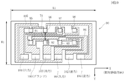
- FIG. 10 is a plan view of a magnetic sensor 90 constituting a conventional magnetic encoder. Eight magnetoresistive effect elements 91 to 98 are provided, and each of the four magnetoresistive effect elements is combined to constitute an A-phase bridge circuit and a B-phase bridge circuit.
- one input terminal 99 and one ground terminal 100 are provided.
- the input terminal 99 and the ground terminal 100 are common terminals for the A-phase bridge circuit and the B-phase bridge circuit.
- the input terminal 99, the ground terminal 100, and the output terminals 101 to 104 are in the vertical direction (Y direction) orthogonal to the relative movement direction (X direction) of the magnetic sensor 90 and are separated from the magnetoresistive effect elements 91 to 98. Further, they are arranged in a row on the one end side in the relative movement direction (X direction).
- the magnetoresistive elements 91 to 98 and the terminals 99 to 104 are electrically connected to each other through a wiring layer 105 formed of Al or the like to form an A-phase bridge circuit and a B-phase bridge circuit. is doing.
- the wiring layer 105 is indicated by oblique lines.
- each of the terminals 99 to 104 is provided at one end side away from the magnetoresistive effect elements 91 to 98 in the vertical direction (Y direction), the vertical dimension W1 of the magnetic sensor 90 is increased.
- the length dimension of the wiring layer 105 between the terminals 99 to 104 and the magnetoresistive elements 91 to 98 is greatly different due to the routing, so that each of the A-phase bridge circuit and the B-bridge circuit is provided. It is necessary to adjust the aspect ratio of the wiring layer 105 in order to obtain the midpoint potential from the output terminals 101 to 104 provided on the wiring layer 105. At this time, as shown in FIG. 10, the width dimension of the wiring layer 105 cannot be changed greatly in the region where the magnetoresistive effect elements 91 to 98 are formed. Unless a portion where the width of the wiring layer 105 is very wide and a resistance value of the wiring layer 105 is greatly lowered is not provided, it is difficult to adjust the resistance value.
- a wide wiring layer 105 is extended and formed on the outer side of the magnetoresistive elements 91, 94, 95, and 98 at both ends in the relative movement direction (X direction). Yes. As a result, not only the vertical dimension W1 of the magnetic sensor 90 but also the horizontal dimension L1 in the relative movement direction is increased.
- the miniaturization of the magnetic sensor 90 cannot be promoted, there is a problem in that the magnet disposed opposite to the magnetic sensor 90 with a space is also required to have a wide shape in the vertical direction, resulting in an increase in manufacturing cost.
- the present invention is to solve the above-described conventional problems, and in particular, to provide a magnetic sensor and a magnetic encoder capable of realizing downsizing by improving the arrangement of terminals electrically connected to the magnetoresistive effect element. With the goal.
- the magnetic sensor according to the present invention is disposed at a position away from the magnetized surface of the magnetic field generating member having a magnetized surface in which the N pole and the S pole are alternately magnetized in the relative movement direction.
- it has a plurality of magnetoresistive effect elements using the magnetoresistive effect whose electric resistance value changes
- a number of the magnetoresistive effect elements constituting a plurality of bridge circuits are provided on the substrate surface, and the magnetoresistive effect elements are arranged in a matrix in the relative movement direction and in the vertical direction perpendicular to the relative movement direction. Are located in Only one of the input terminal and the ground terminal is provided, and the other terminal is provided in plurality.
- the input terminal, the ground terminal, and the output terminal are respectively disposed in regions between the magnetoresistive elements arranged in parallel with an interval in the relative movement direction, and the terminals, the magnetoresistive elements, Are electrically connected by a wiring layer to form a plurality of the bridge circuits.
- each terminal is arranged in a region between the magnetoresistive elements arranged in parallel with a gap in the relative movement direction. Further, only one of the input terminal and the ground terminal is provided, and a plurality of the other terminals are provided.
- the vertical dimension of the magnetic sensor in the direction orthogonal to the relative movement direction can be effectively reduced as compared with the conventional case.
- the degree of freedom in routing the wiring layer between the terminal and the magnetoresistive effect element is increased, and the variation in the length of the wiring layer between the terminal and the magnetoresistive effect element can be reduced as compared with the prior art. Therefore, it is not necessary to change the width of the wiring layer extremely in order to match the midpoint potential.
- both the vertical dimension and the horizontal dimension of the magnetic sensor can be effectively reduced as compared with the prior art, and the magnetic sensor can be downsized.
- only one of the input terminal and the ground terminal is a central terminal disposed at a substantially central position of the magnetoresistive element forming region, and the other terminal is provided in plural.
- the output terminals are preferably provided at substantially point-symmetrical positions around the center terminal.
- the center terminal is an input terminal and the other terminal is a ground terminal.
- the wiring between the terminals of the external circuit electrically connected to each terminal of the magnetic sensor can be appropriately and easily performed.
- the first magnetoresistive effect element, the second magnetoresistive effect element, the third magnetoresistive effect element, and the fourth magnetoresistive effect element constitute an A-phase bridge circuit, and The magnetoresistive effect element and the second magnetoresistive effect element are connected in series via the A-phase first output terminal Va1, and the third magnetoresistive effect element and the fourth magnetoresistive effect element are provided.
- a phase second output terminal Va2 is connected in series, The first magnetoresistive element and the third magnetoresistive element are connected via the input terminal, and the second magnetoresistive element and the fourth magnetoresistive element are connected to the ground terminal.
- the first magnetoresistive element, the second magnetoresistive element, the third magnetoresistive element, and the fourth magnetoresistive element each have a predetermined center-to-center distance in the relative movement direction.
- the first magnetoresistive effect element and the fourth magnetoresistive effect element, and the second magnetoresistive effect element and the third magnetoresistive effect element are juxtaposed in a vertical direction perpendicular to the relative movement direction.
- the fifth magnetoresistive element, the sixth magnetoresistive element, the seventh magnetoresistive element, and the eighth magnetoresistive element constitute a B-phase bridge circuit, and the fifth magnetoresistive element and The sixth magnetoresistive element is connected in series via the B-phase first output terminal Vb1, and the seventh magnetoresistive element and the eighth magnetoresistive element are connected to the B-phase second output. Are connected in series via the terminal Vb2, The fifth magnetoresistive effect element and the seventh magnetoresistive effect element are connected via the input terminal, and the sixth magnetoresistive effect element and the eighth magnetoresistive effect element are connected to the ground terminal.
- the fifth magnetoresistive effect element, the sixth magnetoresistive effect element, the seventh magnetoresistive effect element, and the eighth magnetoresistive effect element are respectively arranged at a distance in the relative movement direction. And is arranged at a position shifted in the relative movement direction by half the center-to-center distance between the magnetoresistive elements constituting the A-phase bridge circuit,
- the fifth magnetoresistive effect element and the eighth magnetoresistive effect element, and the sixth magnetoresistive effect element and the seventh magnetoresistive effect element are arranged in parallel in a vertical direction perpendicular to the relative movement direction.
- the first terminal is a common terminal of one series circuit constituting the A-phase bridge circuit and one series circuit constituting the B-phase bridge circuit.
- the second terminal is preferably a common terminal of the other series circuit constituting the A-phase bridge circuit and the other series circuit constituting the B-phase bridge circuit.
- the magnetoresistive effect elements between the magnetoresistive effect elements are arranged in the direction of displacement of the magnetoresistive effect elements constituting the B phase bridge circuit with respect to the magnetoresistive effect elements constituting the A phase bridge circuit.
- the areas in the relative movement direction are arranged in the order of the first area, the second area, and the third area,
- the A-phase first output terminal Va1 and the A-phase second output terminal Va2 are both provided in the first region, and the B-phase first output terminal Vb1 and the B-phase second output terminal Vb2 are both the third. It is preferable to arrange in the region.
- the terminal provided with only one of the input terminal and the ground terminal is a center terminal disposed in the second region, and the A-phase first output terminal Va1;
- the B-phase first output terminal Vb1 is disposed at a substantially point-symmetrical position with the center terminal as the center, and the A-phase second output terminal Va2 and the B-phase second output terminal Vb2 are centered on the center terminal. It is preferable to arrange at a substantially point-symmetrical position. Thereby, the variation in the length of the wiring layer between the terminal and the magnetoresistive effect element can be more effectively reduced as compared with the conventional case, which can contribute to further miniaturization of the magnetic sensor.
- two or less wiring layers may be arranged between the magnetoresistive elements arranged in parallel in the vertical direction. Thereby, the width dimension of the magnetic sensor can be reduced more effectively.
- the magnetic encoder according to the present invention includes any one of the magnetic sensors described above and the magnetic field generating member.
- miniaturization of the magnetic encoder can be promoted. Further, since the width dimension of the magnetic field generating member can be reduced, the manufacturing cost can be reduced.
- the pair of magnetoresistive elements connected in series are arranged with a distance between the centers of ⁇ in the relative movement direction. It is preferable that
- the present invention can be effectively applied to a magnetic encoder in which the center distance between the N pole and the S pole is ⁇ .
- the size of the magnetic sensor and the magnetic encoder can be reduced as compared with the prior art.
- FIG. 1 is a perspective view of the magnetic encoder of the present embodiment
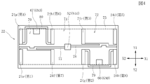
- FIG. 2 is a plan view of the magnetic sensor constituting the magnetic encoder of FIG. 1 (wiring layers are indicated by diagonal lines)
- FIG. FIG. 4 and FIG. 5 are plan views showing a part of the constituent members of the magnetic sensor shown in FIG. 2, and
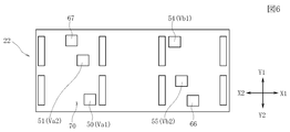
- FIG. 6 explains a terminal arrangement different from FIG.
- FIG. 7 is a cross-sectional view for explaining a laminated structure of magnetoresistive elements
- FIG. 8 is a circuit diagram of the magnetic sensor
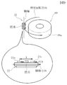
- FIG. 9 is a different embodiment from FIG. It is a schematic diagram of a magnetic encoder.
- the X1-X2 direction is a relative movement direction of the magnet 21 and the magnetic sensor 22.
- the “relative movement direction” refers to the relative movement direction of the magnetic sensor.
- the relative movement direction of the magnetic sensor 22 is the X1 direction. Therefore, when the magnet 21 is fixed and the magnetic sensor 22 moves, the magnetic sensor 22 moves in the X1 direction. When the magnetic sensor 22 is fixed and the magnet 21 moves, the magnet 21 moves in the X2 direction. Note that both the magnet 21 and the magnetic sensor 22 may move.
- the Y1-Y2 direction is the longitudinal direction of the magnetic sensor 22 orthogonal to the relative movement direction.
- the Z1-Z2 direction is a height direction in which the magnet 21 and the magnetic sensor 22 face each other with a predetermined interval.
- the magnetic encoder 20 includes a magnet (magnetic field generating member) 21 and a magnetic sensor 22.
- the magnet 21 has a rod shape extending in the X1-X2 direction shown in the figure, and the surface facing the magnetic sensor 22 is a magnetized surface in which N and S poles are alternately magnetized with a predetermined width in the X1-X2 direction shown in the figure. is there.
- the center-to-center distance (pitch) between the N pole and the S pole is ⁇ .
- ⁇ is 0.5 to 4.0 mm.
- the magnetic sensor 22 includes a substrate 23 and a plurality of magnetoresistive elements 24a to 24h provided on a surface 23a (a surface facing the magnet 21) of the common substrate 23.
- the eight magnetoresistive elements 24a to 24h are arranged in a matrix form, four in the X1-X2 direction and two in the Y1-Y2 direction. As shown in FIG. 1, the distance between the centers of adjacent magnetoresistive elements in the X1-X2 direction is ⁇ / 2.
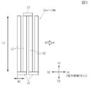
- each of the magnetoresistive effect elements 24a to 24h includes an elongated element portion 12 having an element length L2 longer than an element width W2.
- the element width W2 is 2 to 20 ⁇ m
- the element length L2 is 0.05 to 10 mm.
- the element section 12 has its element length direction in the Y1-Y2 direction shown in the figure, and a plurality of element sections 12 are arranged at predetermined intervals in the X1-X2 direction in the figure. Both end portions in the element length direction of the element portion 12 are connected by the connecting portion 13, and the magnetoresistive effect elements 24a to 24h are formed in a meander shape.
- the connection portion 13 may be an electrode formed of a good conductor such as nonmagnetic Al or a permanent magnet such as CoPt.
- the element portion 12 constituting each of the magnetoresistive effect elements 24a to 24h includes an antiferromagnetic layer 7, a fixed magnetic layer 8, a nonmagnetic layer 9, a free magnetic layer 10, and a protective layer 11 from the bottom. It is formed with a structure laminated in order.
- the stacked structure in FIG. 7 is an example.
- the antiferromagnetic layer 7 is made of IrMn
- the pinned magnetic layer 8 is made of CoFe
- the nonmagnetic layer 9 is made of Cu
- the free magnetic layer 10 is made of NiFe
- the protective layer 11 is made of Ta.
- the element unit 12 includes a laminated portion in which at least the pinned magnetic layer 8 and the free magnetic layer 10 are laminated via the nonmagnetic layer 9.
- An exchange coupling magnetic field (Hex) is generated between the antiferromagnetic layer 7 and the pinned magnetic layer 8, and the magnetization of the pinned magnetic layer 8 is pinned in one direction.
- the magnetization direction of the free magnetic layer 10 is not fixed and fluctuates due to the external magnetic field H.
- the interface between the free magnetic layer 10 and the nonmagnetic layer 9 constituting the element portion 12 faces the plane direction (XY plane direction) parallel to the magnetized surface 21a of the magnet 21. .
- the above configuration is a configuration of a giant magnetoresistive effect element (GMR element) in which the nonmagnetic layer 9 is formed of Cu.
- GMR element giant magnetoresistive effect element
- the nonmagnetic layer 9 is formed of an insulating material such as Al 2 O 3 or MgO.
- TMR element tunnel type magnetoresistive effect element
- the magnetoresistive elements 24a to 24h may be anisotropic magnetoresistive elements (AMR elements).
- the fixed magnetization direction (P direction) of the fixed magnetic layer 8 of each element unit 12 is the relative movement direction (X1 direction).
- the fixed magnetization direction (P direction) of the fixed magnetic layer 8 may be the X2 direction.
- the magnetoresistive effect element 24a is the fourth magnetoresistive effect element 24a
- the magnetoresistive effect element 24b is the sixth magnetoresistive effect element 24b
- the magnetoresistive effect element 24c is the third magnetoresistive effect element 24c
- the magnetoresistive effect element 24d is the fifth magnetoresistive effect element 24d
- the magnetoresistive effect element 24e is the first magnetoresistive effect element 24e
- the magnetoresistive effect element 24f is the seventh magnetoresistive effect element 24f
- the magnetoresistive effect element 24g are referred to as a second magnetoresistive element 24g
- the magnetoresistive element 24h is referred to as an eighth magnetoresistive element 24h.
- the first magnetoresistive element 24e, the second magnetoresistive element 24g, the third magnetoresistive element 24c, and the fourth magnetoresistive element 24a constitute an A-phase bridge circuit.
- the first magnetoresistive element 24 e and the second magnetoresistive element 24 g are connected in series via the A-phase first output terminal (Va1) 50.
- the third magnetoresistive element 24 c and the fourth magnetoresistive element 24 a are connected in series via the A-phase second output terminal (Va 2) 51.
- first magnetoresistive effect element 24e and the third magnetoresistive effect element 24c are connected via the input terminal 52, and the second magnetoresistive effect element 24g and the fourth magnetoresistive effect element 24a are respectively connected. They are connected via ground terminals 66 and 67.
- the A-phase first output terminal (Va1) 50 and the A-phase second output terminal (Va2) 51 are connected to the input section side of the first differential amplifier 58, and the first differential amplifier.
- a differential output can be obtained from 58.
- another B-phase bridge circuit includes the fifth magnetoresistive element 24d, the sixth magnetoresistive element 24b, the seventh magnetoresistive element 24f, and the eighth magnetoresistive element. 24h.
- the fifth magnetoresistive effect element 24d and the sixth magnetoresistive effect element 24b are connected in series via the B-phase first output terminal (Vb1) 54, and the seventh magnetoresistive effect element 24f and the eighth magnetoresistive effect element 24b.
- the resistive effect element 24h is connected in series via the B-phase second output terminal (Vb2) 55. Further, as shown in FIG.
- the fifth magnetoresistive effect element 24d and the seventh magnetoresistive effect element 24f are connected via the input terminal 52, and the sixth magnetoresistive effect element 24b and the eighth magnetoresistive effect element.
- the element 24h is connected via ground terminals 66 and 67, respectively.
- the B-phase first output terminal (Vb1) 54 and the B-phase second output terminal (Vb2) 55 are connected to the input section side of the second differential amplifier 60, and the second differential amplifier. A differential output is obtained from 60.
- the distance between the centers of magnetoresistive elements connected in series by the bridge circuit shown in FIG. 8 is ⁇ .
- the external magnetic fields H1 and H2 enter the magnetoresistive elements 24a to 24h from the magnetized surface 21a of the magnet 21.
- the directions of the external magnetic field H1 and the external magnetic field H2 are different, and when the magnetoresistive effect element is positioned on the magnetic pole, the perpendicular magnetic field is dominant in the magnetic field component with respect to the magnetoresistive effect element. Becomes zero (no magnetic field).
- the first magnetoresistive element 24e and the second magnetoresistive element 24g are separated from each other by ⁇ in the relative movement direction (X1 direction), when the external magnetic field H1 enters the first magnetoresistive element 24e, the second The external magnetic field H2 enters the magnetoresistive element 24g.
- the resistance value of the first magnetoresistive effect element 24e increases by the entry of the external magnetic field H1, while the entry of the external magnetic field H2 occurs.
- the resistance value of the second magnetoresistive element 24g decreases.
- an output waveform of a substantially triangular wave (or may be a substantially sin wave or a substantially rectangular wave) is obtained.
- an output waveform of a substantially triangular wave (or a substantially sin wave or a substantially rectangular wave) can be obtained from the B-phase bridge circuit, but the phase is shifted by ⁇ / 2.
- the moving speed and moving distance of the magnetic sensor 22 or the magnet 21 can be detected. Further, by using two systems of A phase and B phase, it is possible to detect which direction the phase shift direction of the output waveform from the B phase bridge circuit with respect to the output waveform from the A phase bridge circuit is. It becomes possible to know the moving direction.
- the arrangement of the magnetoresistive effect elements 24a to 24h will be described. This will be described with reference to FIG.
- the first magnetoresistive effect element 24e and the second magnetoresistive effect element 24g, the third magnetoresistive effect element 24c, and the fourth magnetoresistive effect element 24a connected in series are respectively Arranged at an interval of ⁇ in the relative movement direction (X1 direction).
- the first magnetoresistive effect element 24e and the fourth magnetoresistive effect element 24a, and the second magnetoresistive effect element 24g and the third magnetoresistive effect element 24c are aligned in the vertical direction (Y1-Y2 direction). It is installed.
- the first magnetoresistance effect element 24e is on the Y2 side in the X2 direction
- the second magnetoresistance effect element 24g is on the Y2 side in the X1 direction
- the third magnetoresistance effect element 24c is in the X1 direction.
- the fourth magnetoresistive effect element 24a is arranged on the Y1 side in the X2 direction on the Y1 side.
- the fifth magnetoresistive effect element 24d and the eighth magnetoresistive effect element 24h, and the sixth magnetoresistive effect element 24b and the seventh magnetoresistive effect element 24f are arranged in the vertical direction (Y1-Y2 direction). It is installed.
- the fifth magnetoresistive element 24d is closer to the X1 side than the third magnetoresistive element 24c
- the sixth magnetoresistive element 24b is connected to the third magnetoresistive element 24c and the third magnetoresistive element 24c.
- the second magnetoresistive effect element 24g is disposed on the X1 side.
- magnetoresistive element formation region first region
- second region second region
- third region third region
- the “magnetoresistive element forming region” is a region including all the magnetoresistive effect elements 24a to 24h, and is an outer edge portion of each magnetoresistive effect element (an edge portion that is not opposed to an adjacent magnetoresistive effect element). ) Is connected by a straight line.
- the “first region”, “second region”, and “third region” are regions between the magnetoresistive effect elements arranged in parallel with a gap in the relative movement direction (X1 direction in the drawing).
- the displacement direction of each magnetoresistive effect element constituting the B phase bridge circuit with respect to each magnetoresistive effect element constituting the A phase bridge circuit (in this embodiment, in the X1 direction shown in the figure, which is the same as the relative movement direction of the magnetic sensor)
- the first region 70, the second region 71, and the third region 72 are arranged in this order. That is, the first region 70 indicates a region surrounded by the first magnetoresistance effect element 24e, the fourth magnetoresistance effect element 24a, the sixth magnetoresistance effect element 24b, and the seventh magnetoresistance effect element 24f.
- the second region 71 is a region surrounded by the second magnetoresistive element 24g, the third magnetoresistive element 24c, the sixth magnetoresistive element 24b, and the seventh magnetoresistive element 24.
- the third region 72 indicates a region surrounded by the second magnetoresistive effect element 24g, the third magnetoresistive effect element 24c, the fifth magnetoresistive effect element 24d, and the eighth magnetoresistive effect element 24h. .
- the input terminal 52 is in the second region 71, and is substantially the horizontal direction (X1-X2 direction) and the vertical direction (Y1-Y2 direction) of the magnetoresistive effect element formation region 75. It is formed at the center position.
- the “substantially central position” is defined as including a deviation amount of about 0 to 20 ⁇ m from the central position.
- the center position includes manufacturing errors.
- Only one input terminal 52 is provided and functions as a common terminal for the A-phase bridge circuit and the B-phase bridge circuit.
- ground terminals 66 and 67 are provided.
- the ground terminal 66 is provided in the third region 72, and the ground terminal 67 is provided in the first region 70.
- the ground terminal 66 is formed at a substantially central position in the lateral direction (X1-X2 direction) of the third region 72, and is formed on the Y2 side when viewed from the input terminal 52.
- the ground terminal 67 is formed at a substantially central position in the lateral direction (X1-X2 direction) of the first region 70, and is formed on the Y1 side when viewed from the input terminal 52.
- the ground terminals 66 and 67 are formed at substantially point-symmetrical positions with the input terminal 52 as the center.
- the “substantially point symmetric position” is defined as including a deviation amount of about 0 to 20 ⁇ m from the point symmetric position.
- the ground terminal 66 is electrically connected to the second magnetoresistive element 24g constituting the A-phase bridge circuit and the eighth magnetoresistive element 24h constituting the B-phase bridge circuit.
- the fourth magnetoresistive element 24a constituting the A-phase bridge circuit and the sixth magnetoresistive element 24b constituting the B-phase bridge circuit are electrically connected to the ground terminal 67. .
- input wiring layers 77 and 78 are formed to extend from the input terminal 52 in the horizontal direction in the figure.
- the input wiring layer 77 extends in a straight line in the left direction (X2 direction) in the figure, and branches in the middle to form a first magnetoresistive effect element 24e constituting an A phase bridge circuit and a seventh phase constituting a B phase bridge circuit. It is connected to the magnetoresistive effect element 24f.
- the input wiring layer 78 linearly extends in the right direction (X1 direction) in the drawing, and branches in the middle to constitute the B-phase bridge circuit with the third magnetoresistive effect element 24c constituting the A-phase bridge circuit. It is connected to the fifth magnetoresistive element 24d.
- a ground wiring layer 79 extends from the ground terminal 66 and is electrically connected to the second magnetoresistive element 24g and the eighth magnetoresistive element 24h.
- a ground wiring layer 80 extends from the ground terminal 67 and is electrically connected to the fourth magnetoresistive element 24a and the sixth magnetoresistive element 24b.
- the routing shape of the ground wiring layers 79 and 80 is a substantially rectangular wave shape.
- both the A-phase first output terminal (Va1) 50 and the A-phase second output terminal (Va2) 51 are formed in the first region 70.
- the A-phase first output terminal (Va1) 50 and the A-phase second output terminal (Va2) 51 are formed at a substantially central position in the lateral direction (X1-X2 direction) of the first region 70.
- the B-phase first output terminal (Vb1) 54 and the B-phase second output terminal (Vb2) are both formed in the third region 72.
- the B-phase first output terminal (Vb1) 54 and the B-phase second output terminal (Vb2) are formed at a substantially central position in the horizontal direction (X1-X2 direction) of the third region 72.
- a first output wiring layer 81 is formed to extend from the A-phase first output terminal (Va1) 50, and the first magnetoresistive effect element 24e constituting the A-phase bridge circuit is formed. And the second magnetoresistance effect element 24g.
- a second output wiring layer 82 is formed to extend from the A-phase second output terminal (Va2) 51, and the third magnetoresistive element 24c and the fourth magnetoresistive element constituting the A-phase bridge circuit. It is electrically connected to the effect element 24a.
- the third output wiring layer 83 is formed to extend from the B-phase first output terminal (Vb1) 54, and the fifth magnetoresistive effect element 24d and the sixth magnetism constituting the B-phase bridge circuit are formed. It is electrically connected to the resistance effect element 24b.
- the fourth output wiring layer 84 is formed to extend from the B-phase second output terminal (Vb2) 55, and the seventh magnetoresistive element 24f and the eighth magnetoresistive constituting the B-phase bridge circuit. It is electrically connected to the effect element 24h.
- Each of the wiring layers 77 to 84 described above is formed in a plane on the surface 23a of the substrate 23 via an insulating layer (not shown). In other words, the wiring layers are not laminated with an insulating layer interposed therebetween.
- the formation surfaces of the wiring layers 77 to 84 may be different from the formation surfaces of the magnetoresistive elements 24a to 24h.
- the wiring layers 77 to 84 are made of a good conductor such as Al.
- the magnetic sensor 22 includes a plurality of magnetoresistance effect elements 24a to 24h constituting an A-phase bridge circuit and a B-phase bridge circuit (see FIGS. 1 and 8).
- the input terminal 52, the ground terminals 66 and 67, and the output terminals 50, 51, 54, and 55 are arranged between the magnetoresistive elements 24a to 24h arranged in parallel with a gap in the relative movement direction (X1 direction). (Refer to FIG. 2, FIG. 4, FIG. 5) of the first region 70, the second region 71, and the third region 72.
- the vertical dimension W3 of the magnetic sensor 22 can be effectively reduced as compared with the conventional case.
- the degree of freedom in routing the wiring layer can be improved by the above (3). That is, unlike the present embodiment, when the number of ground terminals is one as with the input terminal 52, the second magnetoresistive effect element 24g, the fourth magnetoresistive effect element 24a, and the sixth Since all of the magnetoresistive effect element 24b and the eighth magnetoresistive effect element 24h must be connected, the degree of freedom of routing of the wiring layer is reduced, and the length of the wiring layer between each magnetoresistive effect element and the ground terminal The dimensional variation becomes very large.
- the above-described conventional problems can be solved, the degree of freedom of routing of the wiring layer can be improved, and the variation in the length of the wiring layer between each terminal and each magnetoresistive effect element can be made smaller than before. Therefore, it is not necessary to change the width dimension of the wiring layer extremely as in the prior art in order to obtain the midpoint potential from each output terminal 50, 51, 54, 55, and as shown in FIG. 2, FIG. 4, and FIG.
- the layer can be accommodated almost in the magnetoresistive element formation region 75.
- the horizontal dimension L3 and the vertical dimension W3 of the magnetic sensor 22 can be made smaller than before, and the miniaturization of the magnetic sensor 22 can be promoted. Therefore, it is possible to promote downsizing of the magnetic encoder 20 and to reduce the vertical dimension of the magnet 21, thereby reducing the manufacturing cost.
- the horizontal dimension L3 of the magnetic sensor 22 can be in the range of 600 to 4000 ⁇ m, and the vertical dimension W3 of the magnetic sensor 22 can be in the range of 500 to 1000 ⁇ m.
- the reference resistance values of the magnetoresistive elements 24a to 24h are adjusted to be the same.
- the arrangement of the terminals electrically connected to the magnetoresistive effect elements 24a to 24h is further improved, and the magnetic sensor 22 and the magnetism are compared with the conventional one without deteriorating the output characteristics. Miniaturization of the encoder 20 can be realized.
- the input terminal 52 is a central terminal formed at a substantially central position (second region 71) of the magnetoresistive effect element forming region 75.
- the ground terminals 66 and 67 are formed in the first region 70 and the third region 72, respectively, and are formed at substantially point-symmetrical positions around the input terminal 52.
- the input terminal 52 is a common terminal for the A-phase bridge circuit and the B-phase bridge circuit.
- one ground terminal 66 is common to one series circuit constituting the A-phase bridge circuit and one series circuit constituting the B-phase bridge circuit.
- the other ground terminal 67 is a common terminal of the other series circuit constituting the A-phase bridge circuit and the other series circuit constituting the B-phase bridge circuit (FIGS. 2, 4 and 4). 8).
- the input terminal 52 is provided at a substantially central position of the magnetoresistive effect element forming region 75, the first magnetoresistive effect element 24e, the third magnetoresistive effect element 24c, the fifth The input wiring layers 77 and 78 up to the magnetoresistive effect element 24d and the seventh magnetoresistive effect element 24f can be easily adjusted so that the lengths thereof are substantially the same.
- the ground terminals 66 and 67 are provided in the first region 70 and the third region 72, respectively, and are close to the ground terminals 66 and 67 and need to be connected to the ground terminals.
- phase-side magnetoresistive effect element and the B-phase side magnetoresistive effect element are electrically connected to the ground terminals 66 and 67 via the ground wiring layers 79 and 80, respectively. Therefore, the lengths of the ground wiring layers 79 and 80 from the ground terminals 66 and 67 to the magnetoresistive elements can be easily adjusted so as to be substantially the same.
- the fifth magnetoresistive effect element 24d, the sixth magnetoresistive effect element 24b, the seventh magnetoresistive effect element 24f, and the eighth magnetoresistive effect element 24h constituting the B-phase bridge circuit are the A phase Are displaced by ⁇ / 2 in the X1 direction (see FIGS. 1 and 2).
- the regions in the relative movement direction between the magnetoresistive elements are defined as the first region 70, the second region 71, and the third region 72 in the direction of displacement (X1 direction)
- the A phase The first output terminal (Va1) 50 and the A-phase second output terminal (Va2) 51 are provided in the first region 70, and the B-phase first output terminal (Vb1) 54 and the B-phase second output terminal (Vb2) 55 are provided.
- the third region 72 see FIG. 5).
- A-phase first output terminal (Va1) 50 and B-phase first output terminal (Vb1) 54, and A-phase second output terminal (Va2) 51 and B-phase second output terminal (Vb2) 55 are input.
- the terminal 52 is arranged at a substantially point-symmetrical position (see FIG. 5).
- the lengths of the output wiring layers 81 to 84 between the output terminals and the magnetoresistive effect elements according to the above (5) and (6) are inferior to the arrangement of the input terminal 52 and the ground terminals 66 and 67 shown in FIG. 4, the lengths of the output wiring layers 81 to 84 between the output terminals and the magnetoresistive effect elements according to the above (5) and (6). Easy to adjust so that dimensional variation is small.
- both the A-phase first output terminal 50 and the A-phase second output terminal 51 are provided at the substantially central position in the lateral direction of the first region 70, but the variation in the length of the wiring layer is further reduced. As shown in FIG. 6, it is better to form the A-phase first output terminal 50 and the A-phase second output terminal 51 closer to X1 from the substantially central position in the lateral direction of the first region 70. Similarly, the B-phase first output terminal 54 and the B-phase second output terminal 55 are preferably formed closer to X2 from the substantially central position in the lateral direction of the third region 72.
- the ground terminals and the output terminals are arranged in a row in the vertical direction (Y1-Y2 direction) in each of the first region 70 and the third region 72.
- the external circuit pads are provided only on the Y2 side as viewed from the magnetic sensor 22, for example, when the magnetic circuit 22 is disposed slightly shifted in the lateral direction (X1-X2 direction), the ground terminal and the output terminal on the magnetic sensor 22 side There is also an effect that it is easy to wire bond between pads on the external circuit side.
- the length dimensions of the input wiring layers 77 and 78 between the input terminal 52 and each of the magnetoresistive effect elements are obtained by adopting the arrangement of the terminals and the wiring layer routing shown in FIGS.
- the variations in the length dimension of the ground wiring layers 79 and 80 between the ground terminals 66 and 67 and the magnetoresistive effect elements, and the length dimension of the output wiring layers 81 to 84 between the output terminal and the magnetoresistive effect elements are approximately. It can be less than ⁇ / 2, and the variation in the length dimension of the wiring layer between each magnetoresistive effect element and each terminal can be dramatically reduced as compared with the prior art. Therefore, as shown in FIGS. 2, 4, and 5, it is not necessary to provide a portion where the width dimension of the wiring layer is extremely increased, and further miniaturization of the magnetic sensor 22 can be promoted.
- Two or less wiring layers are arranged between the magnetoresistive elements arranged in parallel in the vertical direction (Y1-Y2 direction) (see FIG. 2). According to the arrangement of the terminals and the routing of the wiring layers in the present embodiment, two or less wiring layers are arranged between the magnetoresistive elements arranged in parallel in the vertical direction (Y1-Y2 direction). As a result, the vertical dimension W3 of the magnetic sensor 22 can be further reduced, and further downsizing of the magnetic sensor 22 can be promoted.
- the configuration in which the wiring layer and the terminal partially protrude from the magnetoresistive effect element formation region 75 is not excluded. Actually, in the embodiment of FIG. 2, a part of the wiring layer protrudes from the magnetoresistive element formation region 75. However, the amount of protrusion is sufficiently smaller than that of the prior art. In the present embodiment, it is also possible to arrange the wiring layer and the terminal so as to be all within the magnetoresistive element forming region 75.
- the magnetic sensor 22 linearly moves relative to the magnet 21 as shown in FIG. 1, but as shown in FIG.
- a rotary magnetic encoder having a rotating drum 89 and magnetic sensor 22 alternately magnetized with S poles, and capable of detecting the rotation speed, the number of rotations, and the direction of rotation based on the output obtained by the rotation of the rotating drum 89 It may be.
- FIG. 9 representatively shows a third magnetoresistive element 24c and a fourth magnetoresistive element 24a connected in series.
- the fixed magnetization direction (P direction) of the fixed magnetic layer 8 of each of the magnetoresistive effect elements 24 a to 24 h is the contact point on the center of the substrate 23 of the magnetic sensor 22 in the relative rotation direction of the magnetic sensor 22. Is fixed in a direction parallel to the tangential direction (relative movement direction of the magnetic sensor 22).
- FIG. 1 is a plan view of a magnetic sensor constituting the magnetic encoder of FIG. An enlarged plan view of a magnetoresistive effect element constituting a magnetic sensor
- FIG. 3 is a plan view showing an excerpt of some of the constituent members of the magnetic sensor shown in FIG.
- FIG. 3 is a plan view showing an excerpt of some of the constituent members of the magnetic sensor shown in FIG.
- the partial top view of the magnetic sensor for demonstrating terminal arrangement different from FIG. Sectional drawing for demonstrating the laminated structure of a magnetoresistive effect element, Circuit diagram of magnetic sensor
- FIG. 1 is a schematic diagram of a magnetic encoder of the present embodiment different from FIG.
- the top view of the magnetic sensor which comprises the conventional magnetic encoder
Landscapes
- Physics & Mathematics (AREA)
- General Physics & Mathematics (AREA)
- Condensed Matter Physics & Semiconductors (AREA)
- Chemical & Material Sciences (AREA)
- Engineering & Computer Science (AREA)
- Nanotechnology (AREA)
- Crystallography & Structural Chemistry (AREA)
- Transmission And Conversion Of Sensor Element Output (AREA)
Abstract
L'invention vise à proposer un capteur magnétique et un codeur magnétique, dans lesquels une réduction de dimension est réalisée par amélioration de la topologie des bornes connectées électriquement aux éléments à effet de magnétorésistance en particulier. A cet effet, l'invention porte sur des éléments à effet de magnétorésistance (24a à 24h) qui sont agencés en matrice dans une direction de mouvement relatif (direction X1) et dans une direction verticale (direction Y1-Y2) orthogonale à la direction de mouvement relatif. Une borne d'entrée (52) et deux bornes de masse (66, 67) sont prévues. La borne d'entrée (52), la borne de masse (66) et des bornes de sortie (50, 51, 54, 55) sont respectivement agencées en surfaces (70, 71, 72) parmi les éléments à effet de magnétorésistance respectifs agencés côte à côte et espacés dans la direction de mouvement relatif. Les bornes respectives et les éléments à effet de magnétorésistance respectifs sont connectés électriquement par des couches de câblage (montrées par ombrage) pour constituer deux circuits de pont de phase A et de phase B.
Priority Applications (1)
| Application Number | Priority Date | Filing Date | Title |
|---|---|---|---|
| JP2009548894A JP4914502B2 (ja) | 2008-01-08 | 2008-12-27 | 磁気センサ及び磁気エンコーダ |
Applications Claiming Priority (2)
| Application Number | Priority Date | Filing Date | Title |
|---|---|---|---|
| JP2008001298 | 2008-01-08 | ||
| JP2008-001298 | 2008-01-24 |
Publications (1)
| Publication Number | Publication Date |
|---|---|
| WO2009087937A1 true WO2009087937A1 (fr) | 2009-07-16 |
Family
ID=40853059
Family Applications (1)
| Application Number | Title | Priority Date | Filing Date |
|---|---|---|---|
| PCT/JP2008/073870 Ceased WO2009087937A1 (fr) | 2008-01-08 | 2008-12-27 | Capteur magnétique et codeur magnétique |
Country Status (2)
| Country | Link |
|---|---|
| JP (1) | JP4914502B2 (fr) |
| WO (1) | WO2009087937A1 (fr) |
Cited By (1)
| Publication number | Priority date | Publication date | Assignee | Title |
|---|---|---|---|---|
| JP2022021112A (ja) * | 2020-07-21 | 2022-02-02 | Tdk株式会社 | 磁気センサ |
Families Citing this family (1)
| Publication number | Priority date | Publication date | Assignee | Title |
|---|---|---|---|---|
| JP6500700B2 (ja) * | 2015-08-26 | 2019-04-17 | 株式会社村田製作所 | 抵抗素子用の集合基板 |
Citations (4)
| Publication number | Priority date | Publication date | Assignee | Title |
|---|---|---|---|---|
| JPH0336979U (fr) * | 1989-08-23 | 1991-04-10 | ||
| JP2001174286A (ja) * | 1999-12-16 | 2001-06-29 | Fdk Corp | 磁気エンコーダ |
| JP2003502876A (ja) * | 1999-06-18 | 2003-01-21 | コーニンクレッカ フィリップス エレクトロニクス エヌ ヴィ | 不可逆特性を持つ磁気システムおよびこの種システムを作成し修理し操作する方法 |
| JP2007516437A (ja) * | 2003-12-06 | 2007-06-21 | ローベルト ボツシユ ゲゼルシヤフト ミツト ベシユレンクテル ハフツング | マグネットセンサ装置 |
Family Cites Families (1)
| Publication number | Priority date | Publication date | Assignee | Title |
|---|---|---|---|---|
| JPH0336979A (ja) * | 1989-06-30 | 1991-02-18 | Fanuc Ltd | 可変リラクタンス型acサーボモータ制御方式 |
-
2008
- 2008-12-27 WO PCT/JP2008/073870 patent/WO2009087937A1/fr not_active Ceased
- 2008-12-27 JP JP2009548894A patent/JP4914502B2/ja active Active
Patent Citations (4)
| Publication number | Priority date | Publication date | Assignee | Title |
|---|---|---|---|---|
| JPH0336979U (fr) * | 1989-08-23 | 1991-04-10 | ||
| JP2003502876A (ja) * | 1999-06-18 | 2003-01-21 | コーニンクレッカ フィリップス エレクトロニクス エヌ ヴィ | 不可逆特性を持つ磁気システムおよびこの種システムを作成し修理し操作する方法 |
| JP2001174286A (ja) * | 1999-12-16 | 2001-06-29 | Fdk Corp | 磁気エンコーダ |
| JP2007516437A (ja) * | 2003-12-06 | 2007-06-21 | ローベルト ボツシユ ゲゼルシヤフト ミツト ベシユレンクテル ハフツング | マグネットセンサ装置 |
Cited By (2)
| Publication number | Priority date | Publication date | Assignee | Title |
|---|---|---|---|---|
| JP2022021112A (ja) * | 2020-07-21 | 2022-02-02 | Tdk株式会社 | 磁気センサ |
| JP7173104B2 (ja) | 2020-07-21 | 2022-11-16 | Tdk株式会社 | 磁気センサ |
Also Published As
| Publication number | Publication date |
|---|---|
| JPWO2009087937A1 (ja) | 2011-05-26 |
| JP4914502B2 (ja) | 2012-04-11 |
Similar Documents
| Publication | Publication Date | Title |
|---|---|---|
| JP4870227B2 (ja) | 磁気センサ及び磁気エンコーダ | |
| JP5297539B2 (ja) | 磁気センサ | |
| JP6525335B2 (ja) | シングルチップ・ブリッジ型磁場センサ | |
| JP5066579B2 (ja) | 磁気センサ及び磁気センサモジュール | |
| JP4837749B2 (ja) | 磁気センサ及びそれを用いた磁気エンコーダ | |
| US9182458B2 (en) | Magnetoresistive sensing device | |
| CN107533113B (zh) | 具有增加的snr的磁场传感器 | |
| WO2013001789A1 (fr) | Capteur de courant | |
| JP2009175120A (ja) | 磁気センサ及び磁気センサモジュール | |
| WO2009151023A1 (fr) | Capteur magnétique et module capteur magnétique | |
| WO2009151024A1 (fr) | Capteur magnétique et module capteur magnétique | |
| TWI638140B (zh) | 磁場感測裝置 | |
| CN108072850A (zh) | 磁场感测装置 | |
| JP5171933B2 (ja) | 磁気センサ | |
| JPWO2008081797A1 (ja) | 磁気検出装置 | |
| JP5237943B2 (ja) | 磁気検出装置及びその製造方法、ならびに前記磁気検出装置を用いた角度検出装置、位置検出装置及び磁気スイッチ | |
| WO2011074488A1 (fr) | Capteur magnétique | |
| US12061247B2 (en) | Magnetic sensor | |
| JP4914502B2 (ja) | 磁気センサ及び磁気エンコーダ | |
| JP6506604B2 (ja) | 磁気センサ | |
| JP5453198B2 (ja) | 磁気センサ | |
| JP4874781B2 (ja) | 磁気センサ及びそれを用いた磁気エンコーダ | |
| JP2023046271A (ja) | 磁気センサ | |
| KR20230089608A (ko) | 3축 자기저항 센서 | |
| JP4984962B2 (ja) | 磁気式角度センサ |
Legal Events
| Date | Code | Title | Description |
|---|---|---|---|
| 121 | Ep: the epo has been informed by wipo that ep was designated in this application |
Ref document number: 08869810 Country of ref document: EP Kind code of ref document: A1 |
|
| ENP | Entry into the national phase |
Ref document number: 2009548894 Country of ref document: JP Kind code of ref document: A |
|
| NENP | Non-entry into the national phase |
Ref country code: DE |
|
| 122 | Ep: pct application non-entry in european phase |
Ref document number: 08869810 Country of ref document: EP Kind code of ref document: A1 |