WO2009088002A1 - Plaque vibrante, haut-parleur, système acoustique et procédé permettant de fabriquer une plaque vibrante - Google Patents
Plaque vibrante, haut-parleur, système acoustique et procédé permettant de fabriquer une plaque vibrante Download PDFInfo
- Publication number
- WO2009088002A1 WO2009088002A1 PCT/JP2009/050052 JP2009050052W WO2009088002A1 WO 2009088002 A1 WO2009088002 A1 WO 2009088002A1 JP 2009050052 W JP2009050052 W JP 2009050052W WO 2009088002 A1 WO2009088002 A1 WO 2009088002A1
- Authority
- WO
- WIPO (PCT)
- Prior art keywords
- speaker
- reinforcing
- region portion
- cap
- vibration member
- Prior art date
- Legal status (The legal status is an assumption and is not a legal conclusion. Google has not performed a legal analysis and makes no representation as to the accuracy of the status listed.)
- Ceased
Links
Images






Classifications
-
- H—ELECTRICITY
- H04—ELECTRIC COMMUNICATION TECHNIQUE
- H04R—LOUDSPEAKERS, MICROPHONES, GRAMOPHONE PICK-UPS OR LIKE ACOUSTIC ELECTROMECHANICAL TRANSDUCERS; ELECTRIC HEARING AIDS; PUBLIC ADDRESS SYSTEMS
- H04R1/00—Details of transducers, loudspeakers or microphones
- H04R1/20—Arrangements for obtaining desired frequency or directional characteristics
- H04R1/32—Arrangements for obtaining desired frequency or directional characteristics for obtaining desired directional characteristic only
- H04R1/40—Arrangements for obtaining desired frequency or directional characteristics for obtaining desired directional characteristic only by combining a number of identical transducers
- H04R1/403—Arrangements for obtaining desired frequency or directional characteristics for obtaining desired directional characteristic only by combining a number of identical transducers loud-speakers
-
- H—ELECTRICITY
- H04—ELECTRIC COMMUNICATION TECHNIQUE
- H04R—LOUDSPEAKERS, MICROPHONES, GRAMOPHONE PICK-UPS OR LIKE ACOUSTIC ELECTROMECHANICAL TRANSDUCERS; ELECTRIC HEARING AIDS; PUBLIC ADDRESS SYSTEMS
- H04R5/00—Stereophonic arrangements
- H04R5/02—Spatial or constructional arrangements of loudspeakers
-
- H—ELECTRICITY
- H04—ELECTRIC COMMUNICATION TECHNIQUE
- H04R—LOUDSPEAKERS, MICROPHONES, GRAMOPHONE PICK-UPS OR LIKE ACOUSTIC ELECTROMECHANICAL TRANSDUCERS; ELECTRIC HEARING AIDS; PUBLIC ADDRESS SYSTEMS
- H04R2205/00—Details of stereophonic arrangements covered by H04R5/00 but not provided for in any of its subgroups
- H04R2205/022—Plurality of transducers corresponding to a plurality of sound channels in each earpiece of headphones or in a single enclosure
-
- H—ELECTRICITY
- H04—ELECTRIC COMMUNICATION TECHNIQUE
- H04R—LOUDSPEAKERS, MICROPHONES, GRAMOPHONE PICK-UPS OR LIKE ACOUSTIC ELECTROMECHANICAL TRANSDUCERS; ELECTRIC HEARING AIDS; PUBLIC ADDRESS SYSTEMS
- H04R2231/00—Details of apparatus or processes specially adapted for the manufacture of transducers or diaphragms therefor covered by H04R31/00, not provided for in its subgroups
- H04R2231/001—Moulding aspects of diaphragm or surround
-
- H—ELECTRICITY
- H04—ELECTRIC COMMUNICATION TECHNIQUE
- H04R—LOUDSPEAKERS, MICROPHONES, GRAMOPHONE PICK-UPS OR LIKE ACOUSTIC ELECTROMECHANICAL TRANSDUCERS; ELECTRIC HEARING AIDS; PUBLIC ADDRESS SYSTEMS
- H04R31/00—Apparatus or processes specially adapted for the manufacture of transducers or diaphragms therefor
- H04R31/003—Apparatus or processes specially adapted for the manufacture of transducers or diaphragms therefor for diaphragms or their outer suspension
-
- H—ELECTRICITY
- H04—ELECTRIC COMMUNICATION TECHNIQUE
- H04R—LOUDSPEAKERS, MICROPHONES, GRAMOPHONE PICK-UPS OR LIKE ACOUSTIC ELECTROMECHANICAL TRANSDUCERS; ELECTRIC HEARING AIDS; PUBLIC ADDRESS SYSTEMS
- H04R7/00—Diaphragms for electromechanical transducers; Cones
- H04R7/02—Diaphragms for electromechanical transducers; Cones characterised by the construction
- H04R7/12—Non-planar diaphragms or cones
- H04R7/14—Non-planar diaphragms or cones corrugated, pleated or ribbed
-
- H—ELECTRICITY
- H04—ELECTRIC COMMUNICATION TECHNIQUE
- H04R—LOUDSPEAKERS, MICROPHONES, GRAMOPHONE PICK-UPS OR LIKE ACOUSTIC ELECTROMECHANICAL TRANSDUCERS; ELECTRIC HEARING AIDS; PUBLIC ADDRESS SYSTEMS
- H04R7/00—Diaphragms for electromechanical transducers; Cones
- H04R7/16—Mounting or tensioning of diaphragms or cones
- H04R7/18—Mounting or tensioning of diaphragms or cones at the periphery
- H04R7/20—Securing diaphragm or cone resiliently to support by flexible material, springs, cords, or strands
Definitions
- the present invention relates to a diaphragm, a speaker, an acoustic system, and a method for manufacturing the diaphragm.
- a wood cone diaphragm that uses wood with different propagation speeds in the fiber direction and the non-fiber direction is known.
- An obricone type diaphragm having an asymmetric cross-sectional shape by shifting the position of the voice coil from the center of the diaphragm is also known.
- the manufacturing method of the wood cone type diaphragm may be complicated and the manufacturing cost may be high. Since the Oburicorn type diaphragm has a biased directivity, sound is hardly emitted forward, and in some cases, high-density sound field expression may not be enjoyed.
- the present invention provides a diaphragm, a speaker, an acoustic system, and a diaphragm manufacturing method that are easy to manufacture, have a high product yield, can suppress the occurrence of standing waves, and are excellent in sound field expression. .
- an aspect of the present invention is a vibration member including a first region portion and a second region portion that are integrally formed with each other using an isotropic material. It is provided with a vibration member having a reinforcing portion in the first region portion, which is obtained by press molding in which the pressure applied to the first region portion is stronger than the region portion, and has a higher Young's modulus than the second region portion. A diaphragm having the characteristics is provided.
- a vibration member including a first region portion and a second region portion that are integrally formed with each other using an isotropic material, and is a first member that is more than the second region portion.
- a speaker including a vibrating member having a first region portion having a reinforcing portion having a higher Young's modulus than that of a second region portion, obtained by press molding in which a pressure applied to the region portion is increased.
- a speaker including a first speaker unit and a second speaker unit arranged side by side on the front surface of the cabinet, wherein each of the first and second speaker units is isotropic.
- a vibration member comprising a first region portion and a second region portion that are formed integrally with each other using a material, wherein a band-shaped reinforcing portion having a Young's modulus higher than that of the second region portion is provided in the first region.
- the first speaker unit and the second speaker unit so that at least a part of the reinforcing portions and at least a part of the second speaker unit are oriented in the same direction.
- a speaker in which a speaker unit is arranged.
- Another aspect of the present invention includes a first region portion and a second region portion that are disposed on the front surface of the cabinet, have a substantially conical shape, and are formed integrally with each other using an isotropic material.
- a first speaker unit having a first vibration member having a first reinforcing portion having a higher Young's modulus than that of the second region portion in one region portion; and the first speaker unit arranged in front of the cabinet alongside the first speaker unit.
- a third region portion and a fourth region portion having a substantially conical shape and formed integrally with each other using an isotropic material, wherein the third region portion is more young than the fourth region portion.
- a second speaker unit including a second vibration member having a second reinforcing portion having a high rate, wherein at least a portion of the first reinforcing portion and at least a portion of the second reinforcement are provided. The first and the second so that each part faces the same direction. Providing a loudspeaker formed by placing the speaker units.
- Another aspect of the present invention includes an amplifying unit that amplifies an audio signal, and first and second speakers to which the audio signal is supplied from the amplifying unit, and the first speaker is connected to the first speaker unit.
- the left channel surround audio signal and the center channel audio signal are supplied from the amplifying unit, and the left channel front audio signal is supplied from the amplifying unit to the second speaker unit.
- the right channel surround sound signal and the center channel sound signal are supplied from the amplifying means to the first speaker unit, and the right channel front sound signal is supplied from the amplifying means to the second speaker unit.
- Another aspect of the present invention includes an amplifying unit that amplifies an audio signal, and the first and second speakers according to any one of claims 15 to 30 to which the audio signal is supplied from the amplifying unit,
- the first speaker is a speaker to which the same left channel audio signal is supplied from the amplifying means to the first and second speaker units, and the second speaker is connected to the first and second speaker units.
- an acoustic system is provided which is a speaker to which the same right channel audio signal is supplied from an amplifying means.
- Another aspect of the present invention provides a peripheral portion at a specific position by press molding in which a pressure applied to a specific position of a workpiece formed of an isotropic material is stronger than a pressure applied to the peripheral portion of the specific position.
- a method for manufacturing a diaphragm is provided in which a reinforcing portion having a higher Young's modulus is formed and a diaphragm is formed.
- a diaphragm, a speaker, an acoustic system, and a diaphragm manufacturing method that are easy to manufacture, have a high product yield, can suppress the occurrence of standing waves, and are excellent in sound field expression.
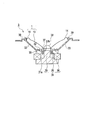
- FIG. 1 is a cross-sectional view showing a speaker unit according to an embodiment of the present invention.
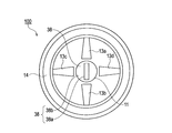
- 2A is a plan view showing the diaphragm according to the embodiment of the present invention
- FIG. 2B is a cross-sectional view when viewed from the AA direction of FIG. 2A.
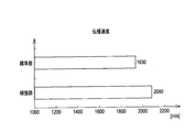
- FIG. 3 is a graph showing the propagation speeds of the reinforcing portion and the standard portion according to the embodiment of the present invention.
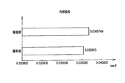
- FIG. 4 is a graph showing the internal loss of the reinforcing portion and the standard portion according to the embodiment of the present invention.
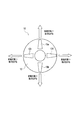
- FIGS. 5 (a) to 5 (d) are plan views showing examples of arrangement of reinforcing portions according to the embodiment of the present invention.
- FIG. 6 (a) to 6 (f) are plan views showing examples of the shape of the reinforcing portion according to the embodiment of the present invention.
- FIG. 7 is an explanatory diagram illustrating characteristics of the vibration member according to the embodiment of the present invention.
- 8A is a graph showing the measurement result of the 8 kHz directivity
- FIG. 8B is a graph showing the measurement result of the 10 kHz directivity.
- FIG. 9A is a graph showing the frequency characteristics of the comparative example
- FIG. 9B is a graph showing the frequency characteristics of the speaker according to the embodiment of the present invention.
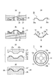
- FIG. 10A to FIG. 10G are process cross-sectional views or plan views showing a method for manufacturing a diaphragm according to an embodiment of the present invention.
- FIG. 10A to FIG. 10G are process cross-sectional views or plan views showing a method for manufacturing a diaphragm according to an embodiment of the present invention.
- FIG. 10A to FIG. 10G are process cross-sectional views
- FIG. 11 is a plan view showing a diaphragm according to a first modification of the present invention.
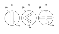
- 12 (a) to 12 (c) are plan views showing examples of the shape of the cap reinforcement region.
- FIG. 13 is an explanatory diagram of a speaker according to a second modification of the present invention.
- FIG. 14 is a diagram showing an audio system according to a third modification of the present invention.
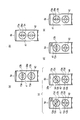
- FIG. 15 is a diagram showing another arrangement example of the speaker units in the speaker shown in FIG.
- FIG. 16 is a cross-sectional view showing a speaker unit according to a fourth modification of the present invention.
- FIG. 17A is a plan view of a diaphragm according to a fourth modification
- FIG. 17B is a cross-sectional view of FIG. 17A viewed from the BB direction.
- a speaker unit (electroacoustic transducer) 3 includes a magnetic circuit 34, a frame 33 disposed on the magnetic circuit 34, and vibrations fixed to the frame 33.
- a plate 1 is provided.
- the magnetic circuit 34 includes a donut-shaped plate 35, a donut-shaped magnet 36 provided under the plate 35, and a pole piece 30.
- a voice coil 31 a is loosely inserted in the magnetic gap 37 between the plate 35 and the pole piece 30.
- the damper 32 is bonded to the voice coil bobbin 31 b and the frame 33.
- the diaphragm 1 has a vibrating member 10 having a cone shape in cross section, and a rubber edge 14 attached over the entire circumference of the outer peripheral portion (edge) of the vibrating member 10.
- the rubber edge 14 is fixed to the frame 33 via a gasket 39.
- the diaphragm 1 has an opening 11 at the center.
- a cap 38 (see FIG. 1) for preventing foreign matter from entering the voice coil 31a is attached to the opening 11.
- the vibrating member 10 is made of an isotropic material (uniform material).
- “isotropic material (homogeneous material)” is different from wood or the like in which the sound propagation speed differs depending on the fiber direction and non-fiber direction, and the sound propagation speed is almost equal in all directions in the diaphragm (etc. Means material).
- the “isotropic material” includes paper such as pulp, plastic such as polypropylene, metal such as aluminum, and the like, but is not limited thereto.
- the vibration member 10 is integrated with the standard portion 12 and the standard portion 12, and has a belt-like shape arranged radially from the opening portion 11 toward the outer peripheral side. Reinforcing portions 13a to 13d are provided.
- the reinforcing portions 13a to 13d are regions (first region portions) that are pressed more strongly than the standard portion 12 (second region portion) in the manufacturing process of the vibration member 10 described later. Therefore, the reinforcing portions 13a to 13d are approximately 10 to 100% higher in material density than the standard portion 12.
- the material density varies depending on the material used. For example, when paper is used as the vibration member 10, the standard portion 12 has a material density of about 0.4 to 0.7 g / cm 3 , and the reinforcing portions 13a to 13d have a material density of about 0.5 to 1. 0 g / cm 3 .
- the reinforcing portions 13 a to 13 d are regions formed so as to have higher rigidity than the standard portion 12 by being pressed stronger than the standard portion 12 in the manufacturing process of the vibration member 10.
- the reinforcing portions 13a to 13d are controlled so that the Young's modulus is about 5 to 15% higher than that of the standard portion 12.
- the Young's modulus varies depending on the material used. For example, when paper is used as the vibration member 10, the Young's modulus of the standard portion 12 is about 1.2 to 2.0 Pa, and the Young's modulus of the reinforcing portions 13a to 13d. Is about 1.3 to 2.5 Pa.
- the reinforcing portions 13a to 13d are pressed to be stronger than the standard portion 12 in the manufacturing process of the vibration member 10, so that the thickness differs from the standard portion 12 by about 10 to 75%.
- the thickness varies depending on the material used. For example, in the vibrating member 10 shown in FIG. 2B, the thickness T1 of the standard portion 12 is about 0.3 mm to 0.35 mm, and the thickness T2 of the reinforcing portions 13a to 13d is about 0.2 mm to 0.00. 25 mm.
- FIG. 3 shows a comparison of propagation speeds of the standard part 12 and the reinforcing parts 13a to 13d when paper is used as the material of the vibration member 10.
- the propagation speed (m / s) of the reinforcing portions 13a to 13d is formed to be about 5 to 10% higher than the propagation speed of the standard portion 12.
- FIG. 4 shows internal losses of the standard part 12 and the reinforcing parts 13a to 13d when paper is used as the material of the vibration member 10.
- the internal loss (tan ⁇ ) of the reinforcing portions 13a to 13d is formed to be 3 to 10% higher than the propagation speed of the standard portion 12.
- the reinforcing portions (first direction reinforcing portions) 13a and 13b are arranged side by side in a first direction (vertical direction in the drawing) passing through the center of the vibration member 10.
- the reinforcing portions (second direction reinforcing portions) 13c and 13d pass through the center of the vibration member 10 and are arranged side by side in a second direction (left and right direction on the paper surface) different from the first direction.
- the first direction and the second direction are set so as to intersect substantially perpendicularly at the center of the vibration member 10, but the present invention is not limited to this.
- the number of reinforcing portions 13a to 13d can be variously changed according to the characteristics of the speaker system on which the vibration member 10 is mounted.
- the two reinforcing portions 13a and 13b may be simply arranged in the vertical direction of the paper surface, or as shown in FIG. 5 (b), four reinforcing portions 13a and 13b are arranged along the diagonal direction of the paper surface.
- the reinforcing portions 13a to 13d may be arranged.
- half-moon shaped reinforcing portions 13a to 13d may be arranged, or as shown in FIG. 5 (d), three pieces extending radially from the opening 11 toward the outer periphery. Reinforcing portions 13a to 13c may be arranged.
- shapes as shown in FIGS. 6A to 6F can be adopted.
- reinforcement is achieved by adopting a shape in which the width in the longitudinal direction becomes gradually narrower from the opening 11 side toward the outer peripheral side (not shown). A change is added to the propagation speed of the vibration (sound) transmitted through the portions 13a and 13b. As a result, it becomes possible to feel the spread due to the reproduced sound in terms of hearing.
- reinforcing members 13a to 13d having a higher Young's modulus and internal loss and a higher propagation speed are arranged on vibrating member 10 as compared with standard portion 12.
- the reinforcing portions 13a to 13d are formed integrally with the standard portion 12 in press molding described later. For this reason, the reinforcing portions 13a to 13d are not peeled off from the vibration member 10, and a part of the vibration member 10 is not damaged as in the case of surface processing with laser light.
- an isotropic material such as paper, plastic, or metal as the material of the vibration member 10
- the size (area) of the reinforcing portions 13a to 13d may not be the same.
- the surface area of the reinforcing portions 13a and 13b is formed larger than the surface area of the reinforcing portions 13c and 13d, so that the surface is perpendicular to the mounting surface. Since the speed of sound becomes faster, it is possible to obtain a sense of hearing that the sound comes out further forward.
- the areas of the reinforcing portions 13a and 13b are made smaller than the areas of the reinforcing portions 13c and 13d, a sense of hearing that the sound spreads in the horizontal direction with respect to the placement surface is obtained.
- FIGS. 8A and 8B show the evaluation results of the directional sensitivity characteristic test of the speaker using the diaphragm according to the present embodiment.
- a speaker using a diaphragm having no reinforcing portion is used as a “comparative example”.
- the speaker according to the comparative example and this embodiment is placed on a turntable, and a microphone is placed at a radius of 1 m from the center of the turntable. Evaluation is performed by rotating the turntable 360 degrees clockwise with the front of the speaker being 0 degrees.
- FIG. 8A when the measurement frequency is 8 kHz, it is understood that the sound level in the speaker according to the present embodiment is increased in all directions compared to the comparative example.
- FIG. 8B when the measurement frequency is 10 kHz, the sound range level output from the front side of the speaker using the diaphragm according to this embodiment is greatly increased compared to the comparative example. I understand that.
- FIG. 9A shows the frequency characteristics of the diaphragm (comparative example) when the reinforcing portions 13a to 13d are not provided
- FIG. 9B shows an example of the frequency characteristics of the diaphragm according to the present embodiment.
- the sound pressure of the speaker according to the present embodiment is higher than that of the comparative example (see FIG. 9A). It can be seen that it is about 1 dB higher.
- a dip is formed in the band of 2 to 3 kHz in FIG. 9A as a comparative example.
- FIG. 9B shows the case shown in FIG. 9B as the present embodiment, it can be seen that the curve is flatter than in FIG. 9A and the occurrence of peaks (dips) is suppressed.
- the diaphragm 1 As described above, according to the diaphragm 1 according to the present embodiment, by arranging the reinforcing portions 13a to 13d, it is possible to increase the output level of the mid range including a lot of vocal components. Moreover, since generation
- FIGS. 10 (a) to 10 (g) a method for manufacturing the diaphragm 1 according to the present embodiment will be described with reference to FIGS. 10 (a) to 10 (g).
- the manufacturing method shown below is an example and it cannot be overemphasized that it can manufacture by various methods besides this.
- a paper machine 21 is placed in the pulp solution 20.
- a net 22 having a central portion formed in a cone shape (conical frustum shape) in advance is placed on the upper surface of the papermaking apparatus 21, a net 22 having a central portion formed in a cone shape (conical frustum shape) in advance is placed.
- the net 22 can be formed of a metal such as Shinchu, but is not limited to this, and can be used as long as it is a strong material having heat resistance.
- pulp solution for example, linter (cotton fiber) 10 wt% + NBKP pulp (coniferous fiber was pulped by kraft method and pulped fiber was bleached) 90 wt% mixed fiber was dispersed in water. Pulp solution is available.
- the paper making apparatus 21 is provided with an opening 23 for discharging excess liquid from the lower side of the net 22 during paper making.
- the papermaking apparatus 21 is gradually pulled up onto the pulp solution 20 to deposit the papermaking material 24 on the net 22. Thereafter, hot air or the like may be blown onto the paper product 24 in order to remove moisture from the paper product 24 on the mesh 22. After the paper product 24 is dried, the paper product 24 is removed from the net 22.
- the paper product 24 removed from the net 22 is sandwiched between a press machine 28 composed of a heated male mold 27 and a female mold 26, and the male mold 27 Press at a predetermined pressure from above.
- a press machine 28 composed of a heated male mold 27 and a female mold 26, and the male mold 27 Press at a predetermined pressure from above.
- the protrusions 27a and 27b are selectively formed on a part of the male mold 27, a part of the papermaking product 24 in contact with the protrusions 27a and 27b is a peripheral area other than that. Pressed more strongly than If the press pressure is too high, the paper product 24 may be damaged, or various physical characteristics such as the sound propagation speed of the paper product 24 may be affected.
- the press pressure is preferably about 3 to 5 kPa.
- the outer peripheral portion 25a of the workpiece 25 formed into a predetermined shape is cut out by cutting. Subsequently, as shown in FIG. 10 (f), the rubber edge 14 is attached over the entire outer periphery of the workpiece 25, and the inner peripheral portion 15 is punched out. As shown in FIG. 10 (g), the diaphragm 1 in which the opening 11 is attached to the center of the vibration member 10 and the rubber edge 14 is attached to the outer periphery is produced.
- the diaphragm 1 according to the present embodiment, by the press molding process shown in FIG. 10C and FIG. 12 and the vibration member 10 having the reinforcing portions 13a to 13d are manufactured. Therefore, it is possible to manufacture a diaphragm that is easy to manufacture and has a high product yield as compared with a case where the diaphragm is processed by laser light or the like.
- the diaphragm 100 according to the first modification differs from the diaphragm 1 shown in FIGS. 2A and 2B in that a cap 38 is attached to the opening 11. .
- the rest of the configuration is substantially the same as that of the diaphragm 1 shown in FIGS.
- the cap 38 includes a belt-shaped reinforcing region (cap reinforcing portion) 38a having a longitudinal direction in the same direction as the reinforcing portions 13a and 13b, and a standard region 38b around the reinforcing region 38a.
- the material of the cap 38 is preferably an isotropic material such as paper, plastic, or metal.
- the reinforcing region 38a and the standard region 38b are formed so as to be integrated with each other by press molding.
- the reinforcing region 38a is a region (first cap region portion) pressed more strongly than the standard region 38b, and has a material density of about 10 to 100% compared to the standard region 38b (second cap region portion). high.
- the material density of the standard region 38b is about 0.4 to 0.7 g / cm 3
- the material density of the reinforcing region 38a is about 0.5 to 1.0 g. / Cm 3 .
- the Young's modulus of the reinforcing region 38a is about 5 to 15% higher than that of the standard region 38b.
- the Young's modulus of the standard region 38b is about 1.2 to 2.0 Pa
- the Young's modulus of the reinforcing region 38a is about 1.3 to 2.5 Pa.
- the reinforcing region 38a has a thickness different from that of the standard region 38b by being pressed more strongly than the standard region 38b in the press working process at the time of manufacture.
- the standard region 38b has a thickness of about 0.3 mm to 0.35 mm
- the reinforcing region 38a has a thickness of about 0.2 mm to 0.25 mm.
- the shape of the reinforcing region 38a is not particularly limited.
- the reinforcing region 38 a may be formed in a strip shape extending in the first direction passing through the center of the cap 38.
- a V-shaped reinforcing region 38a may be formed as shown in FIG. 12B, or a cross-shaped reinforcing region 38a may be formed as shown in FIG. 12C.
- the reinforcing region 38a and the standard region 38b are arranged for the cap 38 in addition to the vibrating member 10.
- the sound speed of the sound transmitted through the cap 38 can be changed depending on the position, so that the generation of standing waves seen when an isotropic member is employed can be suppressed, and a richer sound field expression can be realized.
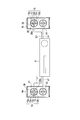
- FIG. 13 shows an example of a speaker 4a, 4b of a type in which two diaphragms shown in FIG.
- the reinforcing portions 13a and 13b are arranged side by side in a substantially vertical direction with respect to the placement surface.
- the reinforcing portions 13c and 13d are arranged side by side in a substantially horizontal direction with respect to the placement surface.
- the reinforcing region 38a provided in the cap 38 is arranged along the same direction as the reinforcing portions 13a and 13b.
- the reinforcing portions 13a and 13b and the reinforcing region 38a by having the reinforcing portions 13a and 13b and the reinforcing region 38a, the standing wave is prevented and the output in the middle range is further strengthened so that the sound comes out forward. Can be given to users. Further, by arranging the reinforcing portions 13c and 13d, it is possible to provide a feeling of sound spread in the horizontal direction on the mounting surface, so that it is possible to provide a speaker capable of realizing a more dense sound field expression.
- FIG. 14 shows an example of an audio system including the speakers 4a and 4b shown in FIG. 13 and the amplifier 6 connected to the speakers 4a and 4b.
- Two speaker units 41 and 42 are arranged on the front surface of the cabinet of the speaker 4a on the left side of the drawing.
- Two speaker units 43 and 44 are arranged on the front surface of the cabinet of the speaker 4b on the right side of the drawing.
- Each of the speaker units 41 to 44 is disposed in the diaphragm 10 having the standard portion 12 and the reinforcing portions (the first direction reinforcing portions 13a and 13b and the second direction reinforcing portions 13c and 13d), and the opening of the diaphragm 10. And a cap 38.
- 1st direction reinforcement part 13a, 13b is arrange
- the 2nd direction reinforcement parts 13c and 13d are arrange
- the second direction reinforcing portions 13c and 13d provide a sense of sound spread in the horizontal direction.
- the sense of spread of the sound in the vertical direction becomes stronger. It is suitable for a speaker for music appreciation.
- the width in the short direction of the second direction reinforcing portions 13c and 13d is larger than the width in the short direction of the first direction reinforcing portions 13a and 13b, the feeling of sound spread in the horizontal direction becomes stronger. For example, it is suitable for use as a home theater speaker that requires a sense of reality. In the speakers 4a and 4b shown in FIG.
- the width in the short direction of the first direction reinforcing portions 13a and 13b is about 5 to 20 compared to the width in the short direction of the second direction reinforcing portions 13c and 13d. It is formed so as to increase by about%. As a result, a high-quality speaker can be provided as a music appreciation speaker, and it can also be sufficiently used as a real home theater speaker.
- the cap 38 is provided with a reinforcing region 38a having a longitudinal direction substantially perpendicular to the mounting surface.
- a reinforcing region 38a having a longitudinal direction substantially perpendicular to the mounting surface.
- the direction of the reinforcing region 38a is rotated by 90 ° counterclockwise with respect to the upper speaker unit 41 to be “V-shaped”.
- the cap of FIG. 12B can be rotated 90 ° clockwise to be arranged in a “mountain shape (inverted V shape)”.
- the direction of the cross of the reinforcing region 38a is more realistic by aligning the direction of the first direction reinforcing portions 13a and 13b and the second direction reinforcing portions 13c and 13d. Sound can be reproduced.
- the speaker unit 41 is connected to the amplifier 6 via a line L1.
- the speaker unit 42 is connected to the amplifier 6 via a line L2.
- the speaker unit 43 is connected to the amplifier 6 via a line L3.
- the speaker unit 44 is connected to the amplifier 6 via a line L4.
- the same left channel audio signal (Lch) is sent to the speaker units 41 and 42 from the amplifier 6 via lines L1 and L2. Entered.
- the same right channel audio signal (Rch) is input to the speakers 43 and 44 from the amplifier 6 via lines L3 and L4.
- the first direction reinforcing portions 13a and 13b and the reinforcing region 38a are arranged so that their orientations are aligned with the mounting surface in the vertical direction. It is desirable.
- the upper and lower speaker units 41 and 42 align the directions of the first direction reinforcing portions 13a and 13b and the speaker units 41 and 42 align the directions of the second direction reinforcing portions 13c and 13d. It is desirable to reproduce the image with a sense of unity when used as.
- the speaker unit 41 sends a left channel surround signal (surroundsurLsurch) and a center channel signal (center) from the amplifier 6 via the line L1.
- ch is input.
- a left channel front signal (front L ch) is input to the speaker unit 42 from the amplifier 6 via a line L2.
- the right channel surround signal (surround R ch) and the center channel signal (center ch) are input from the amplifier 6 to the speaker unit 43 via the line L3.
- a right channel front signal (front R ch) is input to the speaker unit 42 from the amplifier 6 via a line L4.
- the first direction reinforcing portions 13a and 13b and the reinforcing region 38a are arranged so that their directions are aligned with the mounting surface in the vertical direction. Is desirable.
- a portion (reinforcing portion) having a high sound velocity in the direction perpendicular to the placement surface is positively provided.
- the example in which the two speakers 4a and 4b are arranged is shown.
- a plurality of speakers equivalent to the speakers 4a and 4b are connected to the amplifier 6, or a woofer and a tweeter are added.
- three or more speaker units 41 to 44 may be arranged side by side with respect to one speaker 4a.
- the longitudinal directions of the first direction reinforcing portions 13a and 13b and the reinforcing region 38a of the upper and lower speaker units 41 and 42 are substantially horizontal to the mounting surface of the speaker 4a.
- the speed of sound in the horizontal direction becomes faster than in other areas.
- the first direction reinforcing portions 13a and 13b and the reinforcing region 38a of the upper and lower speaker units 41 and 42 are arranged so that the directions thereof are substantially perpendicular to the mounting surface of the speaker 4a.
- the speed of sound in the vertical direction becomes faster than in other areas.
- the speaker unit 41 of FIG. 15B when the left channel surround signal of the 5ch surround signal reproduction system, for example, is input to the speaker unit 41 of FIG. 15B, the user feels audible as the sound squeezes out to the front of the speaker 4a. Can be given to.
- the speaker 4a shown in FIG. 15B is used as a 2ch stereo playback speaker, the same sound signal is input to the speaker units 41 and 42, whereby the reproduced sound emitted from the speaker units 41 and 42 is obtained. Can have a sense of unity.
- the speaker units 42 and 44 on the lower side of the speakers 4a and 4b have the same configuration as that shown in FIG. 14, and the first direction reinforcing portions 13a and 13b of the upper speaker units 41 and 43 are used.
- region 38a is arrange
- the configuration of the lower speaker unit 42 is the same as the configuration of FIG. 14, and the orientations of the first direction reinforcing portions 13a and 13b and the reinforcing region 38a of the upper speaker unit 41 are placed.
- the orientations of the first direction reinforcing portions 13a and 13b and the reinforcing region 38a of the upper speaker unit 41 are placed.
- the configuration of the lower speaker unit 42 is the same as the configuration of FIG. 14, and the orientations of the first direction reinforcing portions 13a and 13b and the reinforcing region 38a of the upper speaker unit 41 are placed. By directing it perpendicular to the surface, it is possible to create a sound field that emphasizes the spread of sound in the vertical direction.
- the conical (cone-shaped) vibration member 10 has been described as an example in FIGS. 1 to 15, but as shown in FIGS. 16 and 17, the vibration member 50 having a dome-shaped cross section is used.
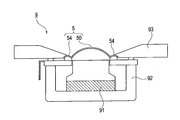
- the speaker unit 9 shown in FIG. 16 includes a magnetic circuit 91, a storage portion 92 that stores the magnetic circuit 91, the diaphragm 5 disposed on the magnetic circuit 91, and a frame 93 that fixes the diaphragm 5.
- FIG. 16 is a cross-sectional view showing a speaker unit according to a fourth modification.
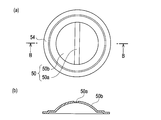
- FIG. 17A is a plan view of a diaphragm according to the fourth modification, and FIG. ) Is a cross-sectional view when viewed from the BB direction.
- the diaphragm 5 has a vibrating member 50 having a dome-shaped cross section, and an edge 54 formed on the entire outer periphery of the vibrating member 50.
- the vibration member 50 the above-mentioned isotropic material, silk, cotton, hemp, chemical fiber, resin film, or the like can be used.
- the vibration member 50 includes a standard portion 50b and a reinforcing portion 50a provided in a band shape at the center.
- the reinforcing portion 50a is a region pressed more strongly than the standard portion 50b in the manufacturing process, and has a higher material density than the standard portion 50b.
- the material density of the standard portion 50b is about 0.4 to 0.7 g / cm 3
- the material density of the reinforcing portion 50a is about 0.5 to 1.0 g / cm 3. cm 3 .
- the Young's modulus of the reinforcing portion 50a is about 5 to 15% higher than that of the standard portion 50b.
- the Young's modulus of the standard part 50b is about 1.2 to 2.0 Pa, and the Young's modulus of the reinforcing part 50a is about 1.3 to 2.5 Pa.
- the standard portion 50b has a thickness of about 0.04 mm to 0.3 mm, and the reinforcing portion 50a has a thickness of about 0.020 mm to 0.25 mm.
- the shape of the reinforcing portion 50a is not particularly limited.
- a shape substantially the same as that of the reinforcing region 38a shown in FIGS. 12 (a) to 12 (c) can be employed.
- the curvature of the dome portion of the vibration member 50 is relatively large, for example, when a material having a higher sound speed than the vibration plate material is pasted on the surface of a general vibration plate, peeling is likely to occur.
- the reinforcing portion 50a and the standard portion 50b are integrated by press molding, so that the reinforcing portion 50a is not peeled off from the surface of the vibrating member 50. Further, by forming by pressing, the vibration member 50 does not hurt as compared with the case where the surface of the vibration member 50 is processed by a chemical solution or a laser. Therefore, the diaphragm 5 that maintains stable quality for a long time can be obtained.
- the present invention can be applied to diaphragms, speakers, acoustic systems, and diaphragm manufacturing methods that can suppress the occurrence of standing waves, have excellent sound field expression, are easy to manufacture, and have a high product yield.
Landscapes
- Health & Medical Sciences (AREA)
- Otolaryngology (AREA)
- Physics & Mathematics (AREA)
- Engineering & Computer Science (AREA)
- Acoustics & Sound (AREA)
- Signal Processing (AREA)
- Diaphragms For Electromechanical Transducers (AREA)
- Audible-Bandwidth Dynamoelectric Transducers Other Than Pickups (AREA)
Abstract
Priority Applications (3)
| Application Number | Priority Date | Filing Date | Title |
|---|---|---|---|
| EP09700720A EP2239959B1 (fr) | 2008-01-07 | 2009-01-07 | Plaque vibrante, haut-parleur, système acoustique et procédé permettant de fabriquer une plaque vibrante |
| CN200980101723.8A CN101919269B (zh) | 2008-01-07 | 2009-01-07 | 扬声器及音响系统 |
| JP2009548931A JP5088377B2 (ja) | 2008-01-07 | 2009-01-07 | スピーカおよび音響システム |
Applications Claiming Priority (10)
| Application Number | Priority Date | Filing Date | Title |
|---|---|---|---|
| JP2008000345 | 2008-01-07 | ||
| JP2008-000345 | 2008-01-07 | ||
| JP2008042113 | 2008-02-22 | ||
| JP2008-042122 | 2008-02-22 | ||
| JP2008-042113 | 2008-02-22 | ||
| JP2008-042115 | 2008-02-22 | ||
| JP2008042118 | 2008-02-22 | ||
| JP2008042122 | 2008-02-22 | ||
| JP2008-042118 | 2008-02-22 | ||
| JP2008042115 | 2008-02-22 |
Publications (1)
| Publication Number | Publication Date |
|---|---|
| WO2009088002A1 true WO2009088002A1 (fr) | 2009-07-16 |
Family
ID=40853115
Family Applications (1)
| Application Number | Title | Priority Date | Filing Date |
|---|---|---|---|
| PCT/JP2009/050052 Ceased WO2009088002A1 (fr) | 2008-01-07 | 2009-01-07 | Plaque vibrante, haut-parleur, système acoustique et procédé permettant de fabriquer une plaque vibrante |
Country Status (4)
| Country | Link |
|---|---|
| EP (1) | EP2239959B1 (fr) |
| JP (1) | JP5088377B2 (fr) |
| CN (1) | CN101919269B (fr) |
| WO (1) | WO2009088002A1 (fr) |
Cited By (1)
| Publication number | Priority date | Publication date | Assignee | Title |
|---|---|---|---|---|
| CN110612726A (zh) * | 2017-05-09 | 2019-12-24 | 搜诺思公司 | 形成音频换能器膜片的系统和方法 |
Families Citing this family (3)
| Publication number | Priority date | Publication date | Assignee | Title |
|---|---|---|---|---|
| JP6048469B2 (ja) * | 2013-10-22 | 2016-12-21 | ヤマハ株式会社 | 電気音響変換器 |
| WO2017054751A1 (fr) * | 2015-09-29 | 2017-04-06 | Sound Solutions International Co., Ltd. | Plaque de renfort pour membrane acoustique et son procédé de fabrication |
| CN206596211U (zh) * | 2016-12-05 | 2017-10-27 | 歌尔丹拿音响有限公司 | 锥盆式的扬声器膜片和扬声器 |
Citations (8)
| Publication number | Priority date | Publication date | Assignee | Title |
|---|---|---|---|---|
| JPS51145312A (en) * | 1975-06-09 | 1976-12-14 | Mitsubishi Electric Corp | Vibration plate for a speaker and its manufacturing method |
| JPS53119023A (en) * | 1977-03-26 | 1978-10-18 | Kenzou Inoue | Moving coil type sound converting vibration plate |
| JPS6147479B2 (fr) * | 1979-05-08 | 1986-10-20 | Mitsubishi Electric Corp | |
| JPS62269599A (ja) * | 1986-05-19 | 1987-11-24 | Mitsubishi Electric Corp | スピ−カ装置 |
| JPH0369999U (fr) * | 1989-11-02 | 1991-07-12 | ||
| JP2001258091A (ja) | 2000-03-13 | 2001-09-21 | Minebea Co Ltd | スピーカ用振動板及びその製造方法 |
| JP2005223807A (ja) * | 2004-02-09 | 2005-08-18 | Pioneer Electronic Corp | 振動板、その製造方法、および、スピーカ装置 |
| JP2005286828A (ja) * | 2004-03-30 | 2005-10-13 | Victor Co Of Japan Ltd | オーディオ再生装置 |
Family Cites Families (5)
| Publication number | Priority date | Publication date | Assignee | Title |
|---|---|---|---|---|
| US6655495B2 (en) * | 2001-10-16 | 2003-12-02 | Matsushita Electric Industrial Co., Ltd. | Loudspeaker damper and loudspeaker |
| US6918461B2 (en) * | 2002-02-22 | 2005-07-19 | Cary L. Christie | Dual mono center channel |
| CA2538292A1 (fr) * | 2003-09-08 | 2005-04-21 | John M. Norton | Haut-parleur audio |
| CN1764327A (zh) * | 2004-10-21 | 2006-04-26 | 程光 | 扬声器振膜 |
| US7606377B2 (en) * | 2006-05-12 | 2009-10-20 | Cirrus Logic, Inc. | Method and system for surround sound beam-forming using vertically displaced drivers |
-
2009
- 2009-01-07 EP EP09700720A patent/EP2239959B1/fr active Active
- 2009-01-07 JP JP2009548931A patent/JP5088377B2/ja active Active
- 2009-01-07 WO PCT/JP2009/050052 patent/WO2009088002A1/fr not_active Ceased
- 2009-01-07 CN CN200980101723.8A patent/CN101919269B/zh active Active
Patent Citations (8)
| Publication number | Priority date | Publication date | Assignee | Title |
|---|---|---|---|---|
| JPS51145312A (en) * | 1975-06-09 | 1976-12-14 | Mitsubishi Electric Corp | Vibration plate for a speaker and its manufacturing method |
| JPS53119023A (en) * | 1977-03-26 | 1978-10-18 | Kenzou Inoue | Moving coil type sound converting vibration plate |
| JPS6147479B2 (fr) * | 1979-05-08 | 1986-10-20 | Mitsubishi Electric Corp | |
| JPS62269599A (ja) * | 1986-05-19 | 1987-11-24 | Mitsubishi Electric Corp | スピ−カ装置 |
| JPH0369999U (fr) * | 1989-11-02 | 1991-07-12 | ||
| JP2001258091A (ja) | 2000-03-13 | 2001-09-21 | Minebea Co Ltd | スピーカ用振動板及びその製造方法 |
| JP2005223807A (ja) * | 2004-02-09 | 2005-08-18 | Pioneer Electronic Corp | 振動板、その製造方法、および、スピーカ装置 |
| JP2005286828A (ja) * | 2004-03-30 | 2005-10-13 | Victor Co Of Japan Ltd | オーディオ再生装置 |
Non-Patent Citations (1)
| Title |
|---|
| See also references of EP2239959A4 * |
Cited By (1)
| Publication number | Priority date | Publication date | Assignee | Title |
|---|---|---|---|---|
| CN110612726A (zh) * | 2017-05-09 | 2019-12-24 | 搜诺思公司 | 形成音频换能器膜片的系统和方法 |
Also Published As
| Publication number | Publication date |
|---|---|
| CN101919269B (zh) | 2014-09-03 |
| JPWO2009088002A1 (ja) | 2011-05-26 |
| EP2239959A4 (fr) | 2011-01-19 |
| JP5088377B2 (ja) | 2012-12-05 |
| EP2239959A1 (fr) | 2010-10-13 |
| EP2239959B1 (fr) | 2013-01-02 |
| CN101919269A (zh) | 2010-12-15 |
Similar Documents
| Publication | Publication Date | Title |
|---|---|---|
| CN101378604B (zh) | 音圈及扬声器 | |
| US7845461B2 (en) | Acoustic diaphragm and speaker | |
| JP5088377B2 (ja) | スピーカおよび音響システム | |
| JP5273174B2 (ja) | 音響振動板 | |
| KR101011996B1 (ko) | 음향 진동판 및 스피커 | |
| JP2010016765A (ja) | スピーカ装置 | |
| JP2010016766A (ja) | 音響システム | |
| JPS58131895A (ja) | スピ−カ−用振動板 | |
| KR20260001301A (ko) | 저음역을 강화한 2웨이 라우드스피커 | |
| TWM578918U (zh) | Speaker diaphragm material and its structure | |
| JP2023142382A (ja) | スピーカ用振動板、およびスピーカ | |
| JP5262998B2 (ja) | スピーカユニット | |
| JP2008160640A (ja) | スピーカ用振動板およびこれを用いたスピーカならびにこのスピーカを用いた電子機器および装置 |
Legal Events
| Date | Code | Title | Description |
|---|---|---|---|
| WWE | Wipo information: entry into national phase |
Ref document number: 200980101723.8 Country of ref document: CN |
|
| 121 | Ep: the epo has been informed by wipo that ep was designated in this application |
Ref document number: 09700720 Country of ref document: EP Kind code of ref document: A1 |
|
| DPE1 | Request for preliminary examination filed after expiration of 19th month from priority date (pct application filed from 20040101) | ||
| ENP | Entry into the national phase |
Ref document number: 2009548931 Country of ref document: JP Kind code of ref document: A |
|
| WWE | Wipo information: entry into national phase |
Ref document number: 2009700720 Country of ref document: EP |
|
| NENP | Non-entry into the national phase |
Ref country code: DE |