WO2009090766A1 - Structure de montage de planche supérieure et bureau - Google Patents
Structure de montage de planche supérieure et bureau Download PDFInfo
- Publication number
- WO2009090766A1 WO2009090766A1 PCT/JP2008/061234 JP2008061234W WO2009090766A1 WO 2009090766 A1 WO2009090766 A1 WO 2009090766A1 JP 2008061234 W JP2008061234 W JP 2008061234W WO 2009090766 A1 WO2009090766 A1 WO 2009090766A1
- Authority
- WO
- WIPO (PCT)
- Prior art keywords
- top plate
- edge
- support
- mounting structure
- engaging
- Prior art date
- Legal status (The legal status is an assumption and is not a legal conclusion. Google has not performed a legal analysis and makes no representation as to the accuracy of the status listed.)
- Ceased
Links
Images




Classifications
-
- A—HUMAN NECESSITIES
- A47—FURNITURE; DOMESTIC ARTICLES OR APPLIANCES; COFFEE MILLS; SPICE MILLS; SUCTION CLEANERS IN GENERAL
- A47B—TABLES; DESKS; OFFICE FURNITURE; CABINETS; DRAWERS; GENERAL DETAILS OF FURNITURE
- A47B21/00—Tables or desks for office equipment, e.g. typewriters, keyboards
- A47B21/03—Tables or desks for office equipment, e.g. typewriters, keyboards with substantially horizontally extensible or adjustable parts other than drawers, e.g. leaves
Definitions
- the present invention relates to a top plate mounting structure that is suitably used when the top plate is inverted and mounted to a support, and to a desk using the top plate mounting structure.
- the present invention has been made paying attention to such a problem, and can make use of the decorative surface of the top plate as it is, and easily and appropriately adopts the use of the front and back reversed or the use of a changed mounting orientation.
- An object of the present invention is to provide a top plate mounting structure and a desk using the top plate mounting structure.
- the top plate mounting structure of the present invention is provided with an engaging portion on a support that supports the top plate, and the engaging portion is detachably engaged with an edge of the top plate so that the top plate is supported by the support. It is characterized by being attached to.
- the engaging portion is slidably provided on the support, and the engaging portion is provided on the edge of the top plate and the uneven portion between the end surface of the edge. It is desirable to engage with each other.
- a pair of engaging portions are provided at a separated position of the support body, and one engaging portion can slide,
- the engaging portion is fixed, the other engaging portion is engaged with the other opposing edge of the top plate, and an unevenness-related portion is formed between the opposing edges and the one engaging relationship.
- the concave / convex related portion is formed between the opposite edge portion of the top plate by sliding the portion.
- the uneven portion there is a relationship in which the tapered concave portion provided on one of the edge of the top plate or the engaging portion in the longitudinal section and the tapered convex portion provided on the other side are engaged.
- the upper surface of the engaging portion and the upper surface of the top plate are configured to be flush with each other.
- the relationship is such that the convex portion provided on the other side is accommodated in the concave portion provided on one of the edge portion of the top plate or the end portion of the engaging portion. In the engaged state, it is apparent that the concave and convex portions are continuously integrated to form a part of the top plate.
- the top plate In order to make it possible to effectively use the front and back surfaces of the top plate, when the top plate is turned upside down, a similar uneven portion is formed between the engaging portion of the support and the common edge of the top plate. It is desirable to be configured. Further, in order to enable the mounting direction of the top plate to be changed effectively, when the top plate is horizontally swung, the unevenness-related portions are respectively provided between the engaging portion of the support and the plurality of edges of the top plate. It is desirable to be configured.
- the top plate mounting structure of the present invention has the configuration described above, using this, the support is mounted on the main top plate of the desk, and the top plate is arranged at a position continuous with the front edge of the main top plate. If the desk is made, the top board can be effectively used as the extended main top board.
- the support body is variable in the mounting position on the main top plate along the width direction of the main top plate, and the top plate is irregular, and the front and back are reversed at least at two places in the width direction.
- the desk form can be variously modified to pursue good usability according to the purpose and application.
- the decorative surface of the top plate can be used as it is, and the top plate is attached so that it can be used easily and appropriately, such as the use of reversed front and back or the use of a changed mounting orientation. It is possible to provide a structure and a desk with the top mounted on the main top using the structure.
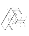
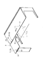
- FIG. 1 shows a desk in which a top plate 3 is attached via a support 2 to a position where the main top plate 1 is expanded using the attachment structure of this embodiment.
- the support 2 is integrally connected to an upright portion 21 having an adjuster 21 a serving as a grounding portion to the floor and the upper end side of the upright portion 21.
- the upright portion 21 and the face plate portion 22 have a rectangular plate shape, and the upper surface of the face plate portion 22 is set as the top plate receiver 2x.
- a pair of engaging portions 23 and 24 are arranged along the opposite sides of the face plate portion 22 so as to be parallel in a state of protruding upward.
- One engaging portion 23 positioned on the side opposite to the main top plate 1 is a movable portion having a protruding portion 23a that is a convex portion, and the other engaging portion 24 positioned on the main top plate 1 side is the protruding portion. It is a fixed thing which has the same protrusion part 24a as the part 23a, Comprising: As for the movable operation
- an appropriate guide mechanism (not shown) is provided between the support piece 23 b and the face plate portion 22.
- the protrusions 23a and 24a of the engaging portions 23 and 24 are formed with tapered (trapezoidal) convex portions 23ax and 24ax that gradually narrow in the direction facing each other as shown in FIG.
- a mounting piece 25 is integrally extended from the face plate portion 22 in a direction away from the standing portion 21, and is substantially parallel to a pedestal 25 a provided on the mounting piece 25.
- a pair of four-sided backing tools 25b are attached. These backing tools 25b have a short side as shown by an imaginary line in the figure with respect to the downward opening width direction of the rail R provided in the lower wall thickness of the main top plate 1 as shown in FIG. Is entered into the rail R in a substantially matched state, and by tightening the bolt v screwed into the backing tool 25b from below at that position, the backing tool 25b is turned horizontally to the position indicated by the solid line in the figure.
- the end 25bx in the long side direction hits the standing wall in the rail R, and then the bolt v is further tightened so that the opening edge r of the rail R is sandwiched between the backing tool 25b and the mounting piece 25 and attached. is there. At this time, the base 25a is closely positioned between the opening edges r of the rail R.
- the face plate portion 22 is kept horizontal and at the same time the attachment piece 25 is brought into close contact with the lower surface 1b of the main top plate 1.
- the protruding portion 24 a of the other engaging portion 24 is arranged in close contact with the front edge 1 c of the main top plate 1 in the attached state of the support 2.
- the top plate 3 of the present embodiment supported by the support 2 is of a different shape having a curved edge 3R in part.
- the trailing edge 32 is longer than the leading edge 31, the outer edge 33 is orthogonal to the leading edge 31 and the trailing edge 32, and the inner edge 34 is orthogonal to the leading edge 31, but the trailing edge. 32 is connected via a curved edge 3R that curves smoothly.
- notches 35 and 36 into which the engaging portions 23 and 24 are fitted are provided in a part of the front edge portion 31 and the rear edge portion 32 of the top plate 3.
- the cutouts 35 and 36 have tapered recesses 35ax and 36ax that fit into the tapered protrusions 23ax and 24ax of the protrusions 23a and 24a as shown in FIG.
- the recesses 35a, 36a for receiving the entire protrusions 23, 24 are formed inside the notches 35, 36.
- the tapered convex portions 23ax, 24ax of the ridges 23, 24 and the tapered concave portions 35ax, 36ax of the notches 35, 36 are symmetrical with respect to the thickness direction and the width direction of the top plate 3.
- the clearance 23a and the protrusion 23a have the same clearance.
- the dimensions are set so that the top plate 3 can be arranged.
- One engaging portion 23 is slidable from this position to a position shown in FIG. 5C where the top plate 3 is tightly sandwiched between at least the other engaging portion 24.
- a concave-convex related portion S2 is formed between the tapered concave portion 36a formed in the notch 36 and the tapered convex portion 24ax of the ridge 24, thereby positioning the top plate 3 in the vertical direction.
- FIG.4 (c) FIG. 1 the protrusion part 23 of the front edge part 31 side of the top plate 3 is made. Fit into the notch 35.
- an unevenness-related portion T1 is formed between the concave portion 35a of the notch 35 and the ridge portion 23 in plan view, whereby the front edge portion 31 of the top plate 3 is positioned in the top plate width direction, and the longitudinal section
- a concave / convex related portion T2 is formed between the tapered concave portion 35a formed in the notch 35 and the tapered convex portion 23ax of the ridge portion 23, thereby positioning the top plate 3 in the vertical direction.
- the slide mechanism has a function of clicking and stopping at the operating end of one of the engaging portions 23.
- the top plate is arranged at a position where the main top plate is extended as shown in FIG. 1, and the upper load is supported by the main top plate 1 on the rear end portion 32 side via the attachment piece 25, and the front end portion 31 side. Is supported by an upright portion 21 that stands on the floor.
- the upper surface 24az and the upper surface 1a of the main top plate 1 are set to be flush with each other.
- the engaging portions 23 and 24 are provided on the support 2 that supports the top plate 3, and these engaging portions 2 and 3 are connected to the edges of the top plate 3.
- the top plate 3 is attached to the support 2 in a state of being fixed in the surface direction and the vertical direction by being detachably engaged with 31 and 32.
- the engaging portion 23 is slidably provided on the support 2, and the engaging portion 23 is provided between the front edge portion 31 of the top plate 3 and the end surface of the front edge portion 31.
- T2 are configured so that the top plate 3 can be reliably positioned and fixed in the direction regulated by the projections and depressions by simply sliding the engagement portion 23.
- the engaging portions 23 and 24 are provided in a pair at a separated position of the support 2, one engaging portion 23 is slidable, the other engaging portion 24 is fixed, and the other engaging portion is provided. 24 is engaged with the rear edge portion 32 which is the other opposing edge portion of the top plate 3, and the concave and convex portions S1 and S2 are formed between the rear edge portion and the end surface of the rear edge portion, and one engagement portion 23 is slid.
- the concave and convex portions T1 and T2 are formed between the top plate 3 and the front edge portion 31 which is one opposing edge portion, the engagement portion 23 provided in a pair on the support body 2, 24, the top plate 3 can be attached so as to be sandwiched from both edges, so that when the main top plate 1 is attached, the processing of the front edge portion 1c of the main top plate 1 is not required. Effective with support 2 with plate 3 attached to main top plate 1 Ri can be attached.
- the concave and convex portions S2 and T2 are tapered convex portions provided in the engaging portions 23a and 24a and tapered concave portions 35a and 36a provided in the edge portions 31 and 32 of the top plate 3 in the longitudinal section.
- 23ax and 24ax are in a relationship of engagement, and the upper surfaces 23az and 24az of the engagement portions 23a and 24a and the upper surface 3a of the top plate 3 are configured to be flush with each other in the engaged state.
- the top surfaces of the concave and convex portions S2 and T2 can be made flush with each other after mounting, so that the top plate 3 can be reliably prevented from being lifted.
- the projections 23a and 24a which are projections provided on the engaging portions 23 and 24 are provided in the recesses 35 and 36 provided on the edges 31 and 32 of the top plate 3 in the plan view. Since it is in a relationship of being engaged so that it can be accommodated, and apparently the recessed portions 35 and 36 and the ridges 23a and 24a are continuously integrated to form a part of the top plate 3, Later, the unevenness related portions S1 and T1 can be apparently assimilated to the top plate 3 to reliably prevent the top plate 3 from being displaced in the planar direction.
- the support 2 is attached to the main top plate 1 of the desk, and the top plate 3 is arranged at a position continuous with the front edge 1c of the main top plate 1. It can be used effectively as a board.
- the mounting position of the support body 2 on the main top plate 1 is variable along the width direction of the main top plate 1, and the top plate 3 is also deformed, for example, as shown in FIG. Therefore, it is possible to change the form of the desk in various ways and pursue good usability according to the purpose and application.
- the support 102 can be attached to the main top 1 in the same manner as described above, and the position of the top 103 can be varied along the width direction of the main top 1. And it can also comprise so that it can arrange
- T1, T2 may be configured.
- a pair of engaging portions 223 and 224 are provided on a support body 202 such as a wagon, and the top plate 203 can be attached so as to be sandwiched from both edge portions by these 223 and 224. Even when there is no place where the edge of the top plate 203 is abutted or hooked, the top plate 3 can be effectively attached to the support 2.
- the decorative surface of the top plate can be used as it is, and the top plate mounting structure can be used easily and appropriately such that the front and back are reversed and the mounting orientation is changed. And it becomes possible to provide the desk which attached the top plate to the main top plate using this.
Landscapes
- Tables And Desks Characterized By Structural Shape (AREA)
Abstract
Il est possible d'employer aisément et de façon appropriée une structure de montage de planche supérieure dans laquelle la surface décorative d'une planche supérieure peut elle-même être utilisée et d'utiliser aisément et de façon appropriée la planche supérieure de sorte qu'elle soit inversée et que sa direction de montage soit modifiée. Un élément de support (2) pour supporter la planche de dessus (3) est prévu avec des parties de mise en prise (23, 24). Les parties de mise en prise (23, 24) sont mises en prise de manière amovible avec les parties de bord (31, 32) de la planche de dessus (3), la planche de dessus (3) pouvant être montée sur l'élément de support (2) dans l'état fixé, à la fois dans la direction du plan et dans la direction verticale.
Applications Claiming Priority (2)
| Application Number | Priority Date | Filing Date | Title |
|---|---|---|---|
| JP2008-007373 | 2008-01-16 | ||
| JP2008007373A JP5207234B2 (ja) | 2008-01-16 | 2008-01-16 | 天板取付構造及びデスク |
Publications (1)
| Publication Number | Publication Date |
|---|---|
| WO2009090766A1 true WO2009090766A1 (fr) | 2009-07-23 |
Family
ID=40885174
Family Applications (1)
| Application Number | Title | Priority Date | Filing Date |
|---|---|---|---|
| PCT/JP2008/061234 Ceased WO2009090766A1 (fr) | 2008-01-16 | 2008-06-19 | Structure de montage de planche supérieure et bureau |
Country Status (2)
| Country | Link |
|---|---|
| JP (1) | JP5207234B2 (fr) |
| WO (1) | WO2009090766A1 (fr) |
Families Citing this family (1)
| Publication number | Priority date | Publication date | Assignee | Title |
|---|---|---|---|---|
| JP6986657B1 (ja) * | 2020-12-14 | 2021-12-22 | Preducts株式会社 | 収納機構 |
Citations (8)
| Publication number | Priority date | Publication date | Assignee | Title |
|---|---|---|---|---|
| JPS5915930Y2 (ja) * | 1981-06-08 | 1984-05-11 | 豊田産業株式会社 | 折畳み机 |
| JPH0335737U (fr) * | 1989-08-17 | 1991-04-08 | ||
| JPH0624533U (ja) * | 1992-09-01 | 1994-04-05 | 小泉産業株式会社 | テーブル |
| JPH07275047A (ja) * | 1994-04-15 | 1995-10-24 | Kokuyo Co Ltd | デスク |
| JPH1057153A (ja) * | 1996-08-23 | 1998-03-03 | Kokuyo Co Ltd | 補助天板 |
| US20020117091A1 (en) * | 2001-02-27 | 2002-08-29 | Seth Stem | Convertable table with reversible leaves |
| JP2003009956A (ja) * | 2001-06-27 | 2003-01-14 | Itoki Crebio Corp | Oa機器用机 |
| JP2006087448A (ja) * | 2004-09-21 | 2006-04-06 | Fuontaajiyu:Kk | 物品載置天板 |
-
2008
- 2008-01-16 JP JP2008007373A patent/JP5207234B2/ja not_active Expired - Fee Related
- 2008-06-19 WO PCT/JP2008/061234 patent/WO2009090766A1/fr not_active Ceased
Patent Citations (8)
| Publication number | Priority date | Publication date | Assignee | Title |
|---|---|---|---|---|
| JPS5915930Y2 (ja) * | 1981-06-08 | 1984-05-11 | 豊田産業株式会社 | 折畳み机 |
| JPH0335737U (fr) * | 1989-08-17 | 1991-04-08 | ||
| JPH0624533U (ja) * | 1992-09-01 | 1994-04-05 | 小泉産業株式会社 | テーブル |
| JPH07275047A (ja) * | 1994-04-15 | 1995-10-24 | Kokuyo Co Ltd | デスク |
| JPH1057153A (ja) * | 1996-08-23 | 1998-03-03 | Kokuyo Co Ltd | 補助天板 |
| US20020117091A1 (en) * | 2001-02-27 | 2002-08-29 | Seth Stem | Convertable table with reversible leaves |
| JP2003009956A (ja) * | 2001-06-27 | 2003-01-14 | Itoki Crebio Corp | Oa機器用机 |
| JP2006087448A (ja) * | 2004-09-21 | 2006-04-06 | Fuontaajiyu:Kk | 物品載置天板 |
Also Published As
| Publication number | Publication date |
|---|---|
| JP2009165657A (ja) | 2009-07-30 |
| JP5207234B2 (ja) | 2013-06-12 |
Similar Documents
| Publication | Publication Date | Title |
|---|---|---|
| JP2017206833A (ja) | 床材の固定構造 | |
| JP5207234B2 (ja) | 天板取付構造及びデスク | |
| JP4330675B2 (ja) | 機器支持用アームのデスク天板への取付装置 | |
| KR102090314B1 (ko) | 책상패널용 멀티탭 보관장치 | |
| JP4168914B2 (ja) | スクリーン | |
| JP5329897B2 (ja) | パネルの支持構造 | |
| JP2014228095A (ja) | クランプ機構 | |
| WO2017047577A1 (fr) | Structure de pied et article de mobilier | |
| JP2003135179A (ja) | 物品収納什器 | |
| JP5536321B2 (ja) | カバーの取付構造 | |
| JP5358288B2 (ja) | スクリーンパネル | |
| TWI550383B (zh) | 一體式電腦 | |
| US6398177B1 (en) | Bracket structure of computer desk | |
| JP6206812B2 (ja) | 床配線装置用のプレート部材及びそれを用いた床配線装置 | |
| JP5027609B2 (ja) | 天板の高さ調節装置 | |
| JP2016108724A (ja) | 木質系手摺およびその組付構造 | |
| JP2007002463A (ja) | 床 | |
| JP2001236142A (ja) | 脇机等におけるパソコン本体支持装置 | |
| JP3202821B2 (ja) | 取付け枠の設置構造 | |
| JP5599302B2 (ja) | 機器保持装置 | |
| JP2012192147A (ja) | 棚受装置 | |
| JP2017176519A (ja) | キャビネット | |
| JP5355885B2 (ja) | 家具 | |
| JP2007289317A (ja) | 棚装置 | |
| CA2616482A1 (fr) | Dispositif de retenue |
Legal Events
| Date | Code | Title | Description |
|---|---|---|---|
| 121 | Ep: the epo has been informed by wipo that ep was designated in this application |
Ref document number: 08777395 Country of ref document: EP Kind code of ref document: A1 |
|
| NENP | Non-entry into the national phase |
Ref country code: DE |
|
| 122 | Ep: pct application non-entry in european phase |
Ref document number: 08777395 Country of ref document: EP Kind code of ref document: A1 |