WO2009090881A1 - Dispositif de rétro-éclairage et d'éclairage - Google Patents
Dispositif de rétro-éclairage et d'éclairage Download PDFInfo
- Publication number
- WO2009090881A1 WO2009090881A1 PCT/JP2009/000144 JP2009000144W WO2009090881A1 WO 2009090881 A1 WO2009090881 A1 WO 2009090881A1 JP 2009000144 W JP2009000144 W JP 2009000144W WO 2009090881 A1 WO2009090881 A1 WO 2009090881A1
- Authority
- WO
- WIPO (PCT)
- Prior art keywords
- cathode fluorescent
- fluorescent lamp
- hot cathode
- bulb
- backlight
- Prior art date
- Legal status (The legal status is an assumption and is not a legal conclusion. Google has not performed a legal analysis and makes no representation as to the accuracy of the status listed.)
- Ceased
Links
Images









Classifications
-
- H—ELECTRICITY
- H01—ELECTRIC ELEMENTS
- H01J—ELECTRIC DISCHARGE TUBES OR DISCHARGE LAMPS
- H01J61/00—Gas-discharge or vapour-discharge lamps
- H01J61/02—Details
- H01J61/12—Selection of substances for gas fillings; Specified operating pressure or temperature
- H01J61/16—Selection of substances for gas fillings; Specified operating pressure or temperature having helium, argon, neon, krypton, or xenon as the principle constituent
-
- G—PHYSICS
- G02—OPTICS
- G02F—OPTICAL DEVICES OR ARRANGEMENTS FOR THE CONTROL OF LIGHT BY MODIFICATION OF THE OPTICAL PROPERTIES OF THE MEDIA OF THE ELEMENTS INVOLVED THEREIN; NON-LINEAR OPTICS; FREQUENCY-CHANGING OF LIGHT; OPTICAL LOGIC ELEMENTS; OPTICAL ANALOGUE/DIGITAL CONVERTERS
- G02F1/00—Devices or arrangements for the control of the intensity, colour, phase, polarisation or direction of light arriving from an independent light source, e.g. switching, gating or modulating; Non-linear optics
- G02F1/01—Devices or arrangements for the control of the intensity, colour, phase, polarisation or direction of light arriving from an independent light source, e.g. switching, gating or modulating; Non-linear optics for the control of the intensity, phase, polarisation or colour
- G02F1/13—Devices or arrangements for the control of the intensity, colour, phase, polarisation or direction of light arriving from an independent light source, e.g. switching, gating or modulating; Non-linear optics for the control of the intensity, phase, polarisation or colour based on liquid crystals, e.g. single liquid crystal display cells
- G02F1/133—Constructional arrangements; Operation of liquid crystal cells; Circuit arrangements
- G02F1/1333—Constructional arrangements; Manufacturing methods
- G02F1/1335—Structural association of cells with optical devices, e.g. polarisers or reflectors
- G02F1/1336—Illuminating devices
- G02F1/133602—Direct backlight
- G02F1/133604—Direct backlight with lamps
-
- H—ELECTRICITY
- H01—ELECTRIC ELEMENTS
- H01J—ELECTRIC DISCHARGE TUBES OR DISCHARGE LAMPS
- H01J61/00—Gas-discharge or vapour-discharge lamps
- H01J61/70—Lamps with low-pressure unconstricted discharge having a cold pressure < 400 Torr
Definitions
- the present invention relates to a backlight and a lighting device, and more particularly to a backlight and a lighting device for a direct-type liquid crystal display provided with a hot cathode fluorescent lamp.
- a cold cathode fluorescent lamp is mainly adopted as a light source of a backlight of a liquid crystal display. Since a cold cathode fluorescent lamp is suitable for reduction in diameter, it is used as a light source of a backlight for which reduction in thickness is required (see, for example, Patent Document 1). Japanese Patent Application Laid-Open No. 2002-116704
- the screen size of the liquid crystal display has been increased, and the backlight has also been enlarged accordingly.
- the cold cathode fluorescent lamp is used as a light source due to the enlargement of the backlight, the lighting circuit becomes complicated, and it is feared that the power consumption increases due to the increase in the number of lamps used.
- the cold cathode fluorescent lamp needs to use a high voltage power supply, since the voltage (driving voltage) required for driving is larger than that of other lamps.
- the voltage (driving voltage) required for driving is larger than that of other lamps.
- the lamp length becomes longer, and the driving voltage tends to be further increased accordingly.
- the cold cathode fluorescent lamp requires a small amount of power to be supplied per lamp, it is necessary to increase the number in order to secure the screen brightness. Therefore, the parts cost is increased and the assembly man-hour is required. There is a high possibility that the problem will come to the surface.
- the inventor of the present invention solves the problem of back light that is becoming more and more apparent as the screen of liquid crystal displays becomes larger, by using a hot cathode fluorescent lamp instead of solving the current mainstream cold cathode fluorescent lamp. I'm trying to
- the present invention has been made in view of the foregoing, and a main object thereof is to provide an image display backlight and illumination device provided with a hot cathode fluorescent lamp with further enhanced efficiency.
- the backlight according to the present invention is a backlight comprising a hot cathode fluorescent lamp and a case for housing the hot cathode fluorescent lamp, and the hot cathode fluorescent lamp comprises a bulb having a fluorescent material formed on the inner surface thereof And a filament provided in the valve and emitting thermoelectrons, wherein the valve contains a sealed noble gas containing krypton gas, and a total pressure of the sealed noble gas is 600 [Pa] or more, and a ratio of krypton gas in the enclosed rare gas is 80 [mol%] or more.
- the proportion of krypton gas is 90 [mol%] or more.
- the total pressure of the enclosed noble gas is 1000 [Pa] or less.
- the cross section of the valve is substantially elliptical.
- the backlight is an image display backlight used for an image display apparatus having a screen size of 32 inches or more.
- a lighting device is a lighting device including a hot cathode fluorescent lamp and a case for housing the hot cathode fluorescent lamp, and the hot cathode fluorescent lamp includes a bulb having a fluorescent material formed on an inner surface thereof. And a filament provided in the valve and emitting thermoelectrons, wherein the valve contains a sealed noble gas containing krypton gas, and a total pressure of the sealed noble gas is 600 [Pa] or more, and a ratio of krypton gas in the enclosed rare gas is 80 [mol%] or more.
- the lighting device further includes a lighting unit for lighting the hot cathode fluorescent lamp
- the housing contains a holding member for holding the hot cathode fluorescent lamp and the lighting unit. It is an illuminating device provided with the case attached to the said holding member, and the glove by which the opening part adheres to the said holding member or the said case so that the said hot cathode fluorescent lamp may be accommodated in an inside.
- the base further includes a lighting unit for lighting the hot cathode fluorescent lamp
- the housing includes a housing portion having a housing space for housing the lighting unit therein;
- the hot cathode fluorescent lamp has a ring-shaped tube axis of the bulb and the housing portion is disposed in the ring of the bulb so that the hot cathode fluorescent lamp It is an illuminating device accommodated in the space formed with the said shade.
- the bulb has two pivoting portions for pivoting about an imaginary axis from the middle portion of the glass tube to both ends or in front of the both ends, and the glass tube in the two pivoting portions
- the axis of the light source is shaped so as to be separated from the virtual axis in a plane orthogonal to the virtual axis as the center moves from the middle portion to the end side.
- the total pressure of the enclosed noble gas in the valve is 600 [Pa] or more, and the proportion of krypton gas in the enclosed noble gas is 80 [mol%] or more.
- the efficiency can be increased compared to a backlight or illumination device provided with a cathode fluorescent lamp.
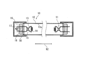
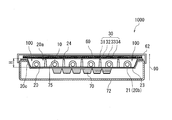
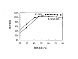
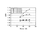
- a plan view showing the configuration of the backlight according to the first embodiment Graph showing the relationship between lamp power (Wla) and lamp efficiency ( ⁇ ) Graph showing relationship between tube surface temperature (° C) and relative efficiency Graph showing the relationship between lamp power and efficiency when the ratio of Kr is changed Graph showing the relationship between lamp power and efficiency when changing the Kr filling pressure
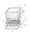
- An exploded perspective view of an image display apparatus including a modified example of a backlight Sectional drawing of the illuminating device which concerns on 2nd Embodiment Schematic of a hot cathode fluorescent lamp according to the second embodiment Schematic of the auxiliary light bulb according to the second embodiment Configuration diagram of the lighting unit according to the second embodiment The circuit diagram of the bulb lighting controller according to the second embodiment
- FIG. 18 is an enlarged cross-sectional view of the end face taken along the line AA of FIG.
- Cross-sectional side view showing a lighting apparatus according to a fifth embodiment Front view showing the inside of the lamp Top view of spiral hot cathode fluorescent lamp Front view of a spiral hot cathode fluorescent lamp
- Cross-sectional front view showing a lighting device according to a sixth embodiment Sectional view of AA position in FIG. 24
- a suitable backlight for a liquid crystal display which is increasingly accelerated in screen size, does not use the currently mainstream cold cathode fluorescent lamp (CCFL), but has one in comparison with the cold cathode fluorescent lamp.
- CCFL cold cathode fluorescent lamp
- HCFL hot cathode fluorescent lamp
- the reason for thinking about such transition is that the contrast ratio in a liquid crystal television can be increased by making use of the "high output" feature of the hot cathode fluorescent lamp, and it is possible to achieve high image quality including moving pictures.
- the number of lamps used as backlights can be significantly reduced, and cost reduction is possible.
- the inventor of the present invention has conducted various studies, and when the ratio of krypton (Kr) of the enclosed gas sealed in the bulb of the hot cathode fluorescent lamp is changed, it operates as a light source for backlight It has been found that the lamp's efficiency improves. In fact, it has been found that the efficiency at room temperature is different from the efficiency at the operating temperature in the temperature environment inside the backlight, and the hot cathode fluorescent lamp exerts higher efficiency at the operating temperature as a light source for backlighting The present invention has been developed.
- Kr krypton
- the backlight 100 according to the first embodiment will be described with reference to FIGS. 1 to 4.
- FIG. 1 is an exploded perspective view schematically showing a configuration of an image display apparatus (liquid crystal display) 1000 including the backlight 100 according to the first embodiment.
- FIG. 2 is a backlight 100 according to the first embodiment.
- the cross-sectional structure of the hot cathode fluorescent lamp 10 which comprises these is shown typically.
- 3 and 4 are a cross-sectional view and a top view showing the configuration of the backlight 100 and the image display apparatus 1000 according to the first embodiment, respectively.
- the backlight 100 includes a plurality of hot cathode fluorescent lamps 10 and a housing 20 for housing the plurality of hot cathode fluorescent lamps 10.
- the bottom surface 20 b of the case 20 of the present embodiment is a reflecting plate 21.
- the backlight 100 is used in an image display (liquid crystal display) having a screen size of 32 inches or more in order to exhibit the characteristics of the hot cathode fluorescent lamp 10.
- the hot cathode fluorescent lamp according to the present embodiment is constituted of a bulb 12 having a phosphor (not shown) formed on the inner surface, and a bulb 14 for emitting thermoelectrons is provided in the bulb 12.
- a sealed rare gas or simply referred to as a "sealed gas" containing argon and krypton gas is sealed.
- the total pressure of the enclosed rare gas is 600 [Pa] or more, and the proportion [mol%] of krypton gas in the enclosed gas is 80 [mol%] or more. The conditions (pressure, proportion) of this krypton gas and its technical significance will be described later.
- FIG. 2 schematically shows a cross-sectional configuration of the hot cathode fluorescent lamp 10 used for the backlight 100 of the present embodiment.
- the hot cathode fluorescent lamp 10 of the present embodiment is used for backlighting, a lamp having a long life is used.
- the hot cathode fluorescent lamp 10 is a lamp having a nominal life of 12,000 hours or more, more preferably a lamp having a nominal life of 20,000 hours or more, or 30,000 hours or more. It should be noted that since the life of a CRT (cathode ray tube) conventionally widely used as a display is about 20000 hours, it is desirable that the lamp has a life longer than that.
- CRT cathode ray tube
- the illustrated hot cathode fluorescent lamp 10 is composed of a straight tubular glass bulb 12 and a pair of electrodes 11 disposed at both ends of the glass bulb 12.
- the glass bulb 12 is made of soda lime glass, or made of barium strontium silicate (soft glass having a softening point of 675 ° C.).
- the outer diameter 12 [mm] of the valve 12 is 12 mm
- the wall thickness is 1.0 mm
- the length is 1010 mm.
- the outer diameter of the valve 12 is 25.5 mm
- the wall thickness is 1.0 mm
- the length is 1550 mm.
- the outer diameter of the valve 12 is 38 mm
- the thickness is 0.9 mm
- the length is 2500 mm.
- the thickness of the valve may be 1.2 [mm].
- a phosphor (not shown) is applied to the inner surface of the glass bulb 12. More specifically, a protective film made of alumina is formed on the inner surface 12 a of the glass bulb 12, and a phosphor layer is laminated on the protective film.
- the phosphor constituting the phosphor layer emits, for example, each color of red (Y 2 O 3 : Eu), green (LaPO 4 : Ce, Tb) and blue (BaMg 2 Al 16 O 27 : Eu, Mn)
- a mixture of rare earth phosphors can be used.
- another rare earth fluorescent substance can be used for fluorescent substance.
- Mercury and a rare gas are enclosed in the glass bulb 12.
- about 5 [mg] of mercury (not shown) and a buffer noble gas (enclosed gas) are enclosed in the glass bulb 12 at a pressure of 600 [Pa] or more at normal temperature.
- the proportion of krypton gas in the buffer noble gas is 80 [mol%] or more (preferably 90 [mol%] or more).
- the total pressure of the buffer noble gas is preferably set to 1000 [Pa] or less.
- the mercury sealed in the bulb 12 may be sealed in the form of an amalgam such as zinc mercury, tin mercury, bismuth, indium mercury and the like in addition to mercury alone.
- the hot cathode fluorescent lamp 10 is a lamp to which a low pressure mercury vapor discharge is applied.
- the principle of light emission is that the electrons are supplied from the electrode to which the electron emitting material is applied by maintaining the temperature at which the thermionic electron is emitted by the discharge (and the other means for heating the electrode). Can be maintained (this is a very different point from the cold cathode).
- mainly ultraviolet light of 254 [nm] is converted into visible light by utilizing it as the excitation source of the phosphor.
- the hot cathode fluorescent lamp 10 is not limited to the one in which the cross section of the bulb 12 is circular, but may be substantially elliptical (in the shape of an ellipse, an oval, a flat shape, etc.).
- One example of the substantially elliptical valve 12 has a major axis / minor axis (outside diameter) of 1.6, but typically, it is in the range of 1.2 ⁇ (L1 / L2) ⁇ 1.8. Can be used. In order to produce the substantially elliptical valve 12, the following procedure may be employed.
- a bulb (glass bulb) having a circular cross section is prepared, and the bulb is heated to be disposed between substantially oval hollow molds (molds), and the mold is sandwiched and deformed by the mold. Can be obtained.
- the alumina and the phosphor to be applied to the inner surface of the bulb 12 may be formed at suitable stages.
- a circular lamp may be made and then heat may be applied to soften and press the glass of the lamp to produce the substantially elliptical valve 12.
- the electrode 11 in the present embodiment is composed of a filament 14, a pair of lead wires 13 for holding the filament 14, and a bead glass 15 for holding the pair of lead wires 13.
- the bead glass 15 is also referred to as bead mount.
- the illustrated electrode 11 is of the so-called glass bead mounting type.
- the filament 14 is made of tungsten, and in an example of the configuration of the present embodiment, has a complex coil shape so as to increase the emitter coating amount to obtain a long life lamp. That is, a thin tungsten wire is wound around a thick tungsten wire so as to cover it loosely to form a long bowl-like structure, and the spirally wound structure is called a double coil.
- the filament 14 is one in which the double coil is spirally wound into a triple coil, or the triple coil is further spirally wound into a quadruple coil.
- the third coil is an electrode coil of 5 to 7 turns.
- the filament 14 is a quadruple coil, it is an electrode coil of 2 to 4 turns.
- the emitters applied to the filament 14 are, for example, oxides of strontium, calcium and barium.
- the amount of emitter applied to the filament 14 is increased, and in the present embodiment, one of the pair of electrodes per one hot cathode fluorescent lamp 10 is used.
- One filament 14 is coated with an emitter of 5.0 mg or more. Note that if the composition of the rare gas is mixed with krypton having a larger atomic weight than argon [100%] instead of argon [100], the emitter hardly scatters from the filament 14, and the lamp life is extended in the technical sense. can do.
- the illustrated electrode 11 is pinch sealed at the sealing portion 16 of the glass bulb 12. Further, an exhaust pipe 17 is sealed at at least one end of the glass bulb 12.
- the exhaust pipe 17 is used for evacuating the inside of the valve 12 or sealing a noble gas, and sealed after the exhaust and sealing. If the exhaust pipe 17 is provided not at one end of the valve 12 but at both ends, there is an advantage that gas exhaust / entrapment can be performed efficiently. Also, thereby, the proportion of impurities inside the valve 12 can be reduced.
- a base 50 is provided at the end of the glass bulb 12 so as to cover the sealing portion 16 and the exhaust pipe 17.
- the connection method between the base portion 50 and the extension portion 18 of the lead wire (13) extended from the sealing portion 16 may be appropriately determined in accordance with the specification of the lamp 10. Specifically, an external terminal (for example, a pin) formed on the base 50 and the extension 18 of the lead wire 13 are electrically connected.
- the backlight 100 including the hot cathode fluorescent lamp 10 is incorporated in the liquid crystal display device 1000, and the backlight 100 in the present embodiment displays a direct-type image. It is a backlight for the device.
- the backlight 100 is used as a planar light source for liquid crystal displays of, for example, 26 inches or more (preferably 32 inches or more, for example, 32 inches, 40 inches, 42 inches, 46 inches, 65 inches, etc.) Ru.
- FIG. 1 does not show the liquid crystal panel 60
- FIG. 3 shows a liquid crystal panel.
- hot cathode fluorescent lamps 10 are arranged.
- the number of hot cathode fluorescent lamps 10 is not limited to this number.
- four to six hot cathode fluorescent lamps 10 can be arranged and operated to operate on a liquid crystal display panel having a screen size of 32 to 46 inches. It is.
- the reflecting plate 21 which is a part of the housing which accommodates the backlight 100 of the present embodiment is made of a metal plate (for example, made of plated iron or aluminum) and has a thickness of 1. It is 5 [mm].
- the reflection sheet 23 is formed on the upper surface (the main surface 20 b of the housing) of the reflection plate 21.
- the reflective sheet 23 is composed of a resin layer of polyethylene terephthalate (PET) in which white titanium oxide (or calcium carbonate) is dispersed, and the thickness thereof is 2.0 [mm].
- PET polyethylene terephthalate
- a pillar 24 for supporting the lower surface of the optical sheet 30 is formed on a part of the upper surface of the reflection plate 21.
- the support 24 is made of white resin.
- the height H of the backlight 100 shown in FIG. 3 (the height from the upper surface of the reflection plate 21 to the surface on which the optical sheet 30 is positioned) is typically 40 mm or less.
- a lighting circuit (a ballast circuit or a ballast) 70 can be disposed below the reflection plate 21 of the backlight 100.
- each lamp 10 is provided with one lighting circuit 70, and thus, six lamps 10 use six lighting circuits 70.
- the number of lighting circuits 70 and the number of lamps 10 can be different.
- the lighting circuit 70 is electrically connected to the lamp 10 through the base 50, and also has a light control function.
- a lower cover 72 is provided under the reflecting plate 21 so as to accommodate the lighting circuit 70.
- the lower cover 72 is made of a metal plate having a thickness of 1.5 mm. In the space between the lower cover 72 and the reflecting plate 21, for example, a wire is disposed.
- the lower cover 72 may not be provided in the backlight 100.
- the lighting circuit 70 can be disposed in the case of a liquid crystal display (for example, a liquid crystal television).
- a lamp holder 75 for holding the lamp 10 is provided at the end of the reflection plate 21.
- the lamp holder 75 is made of, for example, high brightness silicon rubber.
- the optical sheet 30 is disposed in the opening 20 a of the casing of the backlight 100.
- the optical sheet 30 includes, in order from the top, a polarizing sheet 31 (Dual Brightness Enhancement Film (DBEF manufactured by Sumitomo 3M, thickness 0.440 [mm]), a lens sheet 32 (thickness mm], diffusion sheet 33 (thickness 0.113 [mm]), and diffusion plate 34 (thickness 2.0 [mm]). It is also possible to further provide a lens sheet on the lower surface of the diffusion plate 34.
- DBEF Direct Brightness Enhancement Film
- a liquid crystal panel (for example, about 2 mm in thickness) 60 is disposed, and an upper cover 62 is disposed to cover the liquid crystal panel 60 and the optical sheet 30.
- the upper cover 62 is made of, for example, a metal plate having a thickness of 1.5 mm.
- the image display area 65 (see FIG. 4) in this example is 1018 [mm] ⁇ 573 [mm] in the 46-inch size, it is of course not limited to that size, and may be another size.
- the periphery of the sealing portion 16 of the lamp 10 is covered as a frame area in order to hide the non-lighting portion of the lamp 10, and the non-lighting portion is not visible to the outside.
- the direction in which the liquid crystal panel 60 is positioned as viewed from the backlight 100 is taken as a screen direction 90.
- FIG. 5 is a graph showing the relationship between lamp power (Wla) and lamp efficiency ( ⁇ ).
- the ambient temperature is not room temperature but 60 [.degree. C.] corresponding to the temperature in the backlight.
- the filling gas is Ar 50 [mol%] / Kr 50 [mol%]
- the lamp efficiency ( ⁇ ) is deteriorated when the filling gas pressure is increased from 450 [Pa] to 600 [Pa].
- the filling gas is Kr 100 [mol%] at an ambient temperature of 60 [° C.]
- raising the filling gas pressure from 450 [Pa] to 600 [Pa] unexpectedly improves the lamp efficiency ( ⁇ ) It was found to do.
- the tube surface temperature is a temperature substantially at the center of the bulb, and is often the coldest point of the fluorescent lamp in which the mercury vapor pressure in the bulb is determined.
- the results are shown in FIG. That is, the tube surface temperature is about 40 [° C.] in the room temperature region used in general illumination lamps, and the relative efficiency is higher at Ar 50 [mol%] / Kr 50 [mol%], but the ambient temperature is 60 [60 In the region of [° C.] or higher, the tube surface temperature is 70 ° C. or higher, and in this case, the case of Kr 100 [mol%] is high.
- the general illumination lamp has a temperature higher than the atmospheric temperature normally used, specifically 60 [° C.] or more .
- the ambient temperature is high (for example, 60 ° C. or more) in the operating environment of the backlight 100 It can not but become).
- the ambient temperature is high (for example, 60 ° C. or more) in the operating environment of the backlight 100 It can not but become).
- the higher the ratio of Kr and the higher the pressure of Kr the higher the lamp efficiency. It is derived that is preferable.
- FIG. 7 is a graph showing the relationship between the sum (Wtotal) of the lamp power and the power for preheating the filament and the luminous efficiency of the lamp when the ratio of Kr is changed at the enclosed gas pressure of 600 [Pa].
- the ambient temperature here is 60 [.degree. C.], and the efficiency is based on Ar50 [mol%] Kr50 [mol%] at 600 [Pa] (1.00).
- FIG. 8 is a graph which shows the relationship between lamp electric power (Wtotal) at the time of changing enclosed pressure by Kr100 [mol%], and lamp efficiency. Also here, the ambient temperature is 60 ° C., and the efficiency is based on the case (1.00) where Ar 50 [mol%] Kr 50 [mol%] is 600 [Pa].
- the filling pressure of Kr100 [mol%] is 300 [Pa], 450 [Pa], 600 [Pa], 900 [Pa] compared to the standard of Ar 50 [mol%] Kr 50 [mol%]. ] And the efficiency is improving in order.
- the sealing pressure is preferably 600 [Pa] or more from the viewpoint of obtaining an improvement in efficiency as a merit compared to the standard. However, if the filling pressure exceeds 1000 [Pa], the starting voltage becomes too high, so it is preferable to set the filling pressure to 1000 [Pa] or less at that point.
- a light shielding material for example, a lens sheet
- an auxiliary reflection plate can be introduced to the reflection plate 21.
- FIG. 9 shows a configuration example of the backlight 100 in which the auxiliary reflecting plate 22 is provided on a part of the reflecting plate 21.
- a part of the reflection plate 21 is bent in a convex shape (triangular shape) to constitute the auxiliary reflection plate 22.
- a reflective sheet is formed on the upper surface (main surface 20 b of the housing) of the reflective plate 21 including the auxiliary reflective plate 22.
- a pillar 24 for supporting the lower surface of the optical sheet 30 is formed at a part of the apex (or ridge line) of the auxiliary reflection plate 22.
- Japanese Patent Application Laid-Open No. 52-146072 discloses a non-circular cross-sectional annular fluorescent lamp.
- Kr65 [mol%] / Ar 35 [mol%] is described in the same publication, when Kr is 80 [mol%] or more, the lamp current becomes a predetermined value or more and it is inconvenient to exceed the JIS standard value.
- the fluorescent lamp disclosed in the same publication is a lamp for general illumination used at room temperature, which is different from the backlight of the present embodiment.
- FIG. 10 is a cross-sectional view of the illumination device according to the second embodiment.
- a hot cathode fluorescent lamp 203 includes a hot cathode fluorescent lamp 203, an auxiliary light bulb (corresponding to “light emitter” in the present invention) 204, a hot cathode fluorescent lamp 203 and
- the holding member 205 for holding the auxiliary light bulb 204, the hot cathode fluorescent lamp 203 and the auxiliary light bulb 204 in the holding member 205 are mounted on the side opposite to the side where the heat cathode fluorescent lamp 203 and the auxiliary light bulb 204 are lit (lit)
- a lighting unit 207 for holding the case, a case 209 attached to the holding member 205 for housing the lighting unit 207 inside, and an opening portion for housing the hot cathode fluorescent lamp 203 and the auxiliary light bulb 204 inside.
- FIG. 11 is a schematic view of a hot-cathode fluorescent lamp according to the second embodiment. Note that a part of the glass tube 213 is cut away so that the inside of the hot cathode fluorescent lamp 203 can be seen.
- the hot cathode fluorescent lamp 203 includes a bulb 231 formed by bending the glass tube 213, and an electrode 233 sealed to the end portions 203a and 203b of the bulb 231. Although only the electrode 233 at one end 203a of the hot cathode fluorescent lamp 203 appears in FIG. 11, an electrode of the same configuration is sealed at the other end 203b of the hot cathode fluorescent lamp 203. . Further, the end of the bulb 231 and the end of the glass tube 213 are also the ends 203a and 203b of the hot cathode fluorescent lamp 203, and "203a" and "203b" are used as the reference numerals of these ends.
- the central portion of the glass tube 213 (this central portion is also referred to as “the tip of the bulb” and “203 c” is used) is located on the imaginary pivot axis A, and both side portions of the central portion are It has a double spiral shape in which the circumference of the pivot axis A is pivoted in a fixed direction (in FIG. 11, "B") at a fixed pivot radius.
- valve 231 is a first pivoting around the pivot axis A while moving in a constant direction (for example, downward in FIG. 11) along the pivot axis A at a constant pivot radius. It has the turning part 231a, the 2nd turning part 231b, and the continuous part 231c which follows two turning parts 231a and 231b. In addition, you may comprise a valve by one glass tube, and may comprise them by multiple pieces.
- the first pivoting portion 231a and the second pivoting portion 231b have the same pivoting pitch (the amount of movement on the pivoting axis A during one rotation around the pivoting axis A, which is "P1" in the figure. ) And the distance between the axis of the glass tube 213 constituting the first turning part 231a and the axis of the glass tube 213 constituting the second turning part 231b ().
- "P2" in the figure is substantially constant except for the vicinity of the end portions 203a and 203b of the valve 231 (for example, the portion inserted into the holding member 205 in the valve 231).
- the dimension line of P1, P2 in FIG. 11 passes the center (axial center) of the glass tube 213 in each turning part 231a, 31b.
- the turning pitch may be constant or may be changed, or may be changed with a constant regularity.
- the number of turns to turn around the turning axis A is determined by the specifications (rated power etc.) of the lighting device, and the glass tube 213 near the end portions 203a and 203b of the bulb 231 extends in the direction in which the turning axis A extends.
- the turning of the turning axis A is made so as to widen the gap with the adjacent glass tube 213.
- a phosphor layer 235 is formed on the inner surface of the bulb 231 (glass tube 213).
- This phosphor layer 235 contains one or more types of phosphors, for example, phosphors of rare earths.
- mercury which is a light-emitting substance and a rare gas as a buffer gas are enclosed.
- the rare gas contains krypton gas, the total pressure of the rare gas is 600 [Pa] or more, and the ratio of krypton gas in the rare gas is 80 [mol%] or more (preferably 90). [Mol%] or more). Further, the total pressure of the rare gas is preferably set to 1000 [Pa] or less.
- the electrode 233 as shown in FIG. 11, includes a filament coil 241 and a pair of lead wires 243 and 245 for supporting the filament coil 241.
- a filament coil 241 and a pair of lead wires 243 and 245 for supporting the filament coil 241.
- bead glass 247 bead glass type.
- the bead glass 247 When the bead glass 247 is located outside the valve 231, it may be removed after the electrode 233 is sealed to the valve 231, or may be left as it is. Of course, it may exist in the valve 231.
- the filament coil 241 is made of, for example, double-turned (coiled) strands made of tungsten, and is filled with an electron-emitting substance. Further, the lead wires 243 and 245 may be integrated by connecting a plurality of metal wires, or may use one metal wire as it is.
- the end portion 203 a of the valve 231 is pinch sealed (crush sealed) at a portion of the pair of lead wires 243 and 245 located between the bead glass 247 and the filament coil 241 of the electrode 233. Is sealed to the valve 231.
- FIG. 12 is a schematic view of the auxiliary light bulb according to the second embodiment.
- the auxiliary light bulb 204 is lighted in accordance with the start time (so-called “lighting start time”) when the lighting device 200 is lighted, and is, for example, a filament light bulb having a filament coil 251, It has better characteristics than the luminous flux rising characteristics of the hot cathode fluorescent lamp 203.
- the auxiliary light bulb 204 includes a glass bulb 250 and a stem 252 holding the filament coil 251, and the stem 252 is sealed to the glass bulb 250.
- the glass bulb 250 has a cylindrical shape (the cross-sectional shape is a circular shape). Further, in FIG. 12, since the glass bulb 250 is transparent, the members such as the stem 252 inside are shown by solid lines.
- the stem 252 includes a filament coil 251, a pair of lead wires 253 and 254 for supplying power to the filament coil 251 and holding the filament coil 251, and the glass bulb 250 after the stem 252 is stem sealed to the glass bulb 250.
- a thin tube 255 for exhausting the inside and the like, and a flare 256 for holding the thin tube 255 and the pair of lead wires 253 and 254 are provided.
- the filament coil 251 is, for example, a double-turned (coiled) wire made of a tungsten material, and as shown in FIG. 12, the central portion 251c (the center in the coil axial direction) is used. It bends and as a whole, it has a reverse "V" shape expanding to the opening side of the glass bulb 250, and its end portions 251a and 251b are attached to the pair of lead wires 253 and 254.
- a hanger 257 for suspending the filament coil 251 by locking the central portion 251c of the filament coil 251 is provided at an end of the thin tube 255 located in the glass bulb 250. There is.
- the lead wires 253 and 254 may be integrated by connecting a plurality of metal wires, or may use one metal wire as it is.
- a silica light bulb is used as a light emitter (auxiliary light bulb), but another light emitter may be used.
- Other light emitters include LED elements, light bulbs other than silica light bulbs (for example, krypton light bulbs) and the like. In order to raise the temperature of the bulb immediately after the start of lighting and improve the luminous flux rising characteristics, it is necessary for the luminous body to reach the temperature of the bulb or more at the time of light emission.
- FIG. 13 is a configuration diagram of a lighting unit according to the second embodiment.
- the lighting unit 207 mainly includes a rectifier 261, a smoother 262, a switching + ballast 263, a bulb lighting controller 264, and the like.
- a switching + ballast for lighting the hot cathode fluorescent lamp 203 for example, a series inverter type circuit is used.
- an example of the lighting unit 207 will be described.
- the rectifier 261 rectifies commercial low frequency alternating current and converts it into direct current, and is constituted of, for example, four diode bridge elements and the like.
- the smoothing unit 262 smoothes the direct current output from the rectifier 261, and includes, for example, electrolytic capacitors C1 and C2 (so-called voltage doubler rectifiers).
- the lighting unit 207 is connected to a commercial low frequency AC power supply via the base 223.
- diodes D1 and D2 for preventing a backflow of current from the smoother 262 to the rectifier 261 are connected.
- the switching + ballast 263 supplies high frequency power to the hot cathode fluorescent lamp 203 using the output from the smoother 262 and stabilizes the current change generated in the hot cathode fluorescent lamp 203 during lighting.
- the switching action is achieved by, for example, a pair of switching elements (for example, a transistor or the like), a coupling capacitor, and the like, and the stabilizing action is achieved by a choke coil, a resonance capacitor, and the like.
- an IC chip is used, and for example, the above-described pair of switching elements and the like are integrated.
- the choke coil for the ballast and the resonant capacitor also constitute a resonant circuit for lighting the hot cathode fluorescent lamp 203 (breakdown).
- the auxiliary light bulb 204 is turned on via the wires (feed paths) L1 and L2 connected to the output side of the rectifier 261, and control of lighting and extinguishing is performed by the light bulb lighting controller 264.
- the bulb lighting controller 264 is connected to the output side of the smoother 262 via the wires L3 and L4, and when a predetermined condition (for example, after 60 [sec] has elapsed since the start of lighting), the auxiliary bulb Turn off the power supply to 204 and turn it off.
- a thermal fuse 266 is connected between the rectifier 261 and the base 223.
- the power supply to the rectifier 261 side is stopped. It is like that.
- the auxiliary light bulb 204 which should normally be turned off is kept on without turning off after a predetermined time has passed since the lighting start, or the electrode 233 in the hot cathode fluorescent lamp 203 is at the end of its life There are cases such as approaching.
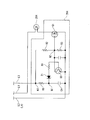
- FIG. 14 is a circuit diagram of a bulb lighting controller according to a second embodiment.
- the bulb lighting controller 264 includes, for example, two transistors Q1 and Q2, a resistor R1, a capacitor C4 and the like, and the auxiliary bulb 204 is turned on / off in the on / off state of the transistor Q1.
- the transistor Q1 connected to the auxiliary light bulb 204 is turned on to turn on the auxiliary light bulb 204, and when the auxiliary light bulb 204 is turned on and a predetermined time elapses, the partial pressure of the connection node N1 becomes a predetermined value.
- the transistor Q1 (which is a switching element) is turned off, and the auxiliary light bulb 204 is turned off.
- One lead of the auxiliary light bulb 204 is connected to the wiring L1, and the other lead is connected to the drain of the transistor Q1.
- the source of the transistor Q1 is connected to the wiring L4 (L2), and the gate is connected to the collector of the transistor Q2.
- the base of the transistor Q2 is connected to the connection node N1 via the resistor R4 and the Zener diode Z1, and the emitter of the transistor Q2 is connected to the wiring L2.
- the connection node N1 is connected to the wiring L3 via the resistor R1 and the connection node N3, and is connected to the wiring L4 (L2) via the capacitor C4.
- connection node N2 between the collector of the transistor Q2 and the gate of the transistor Q1 is connected to the connection node N3 on the input side of the resistor R1 connected to the wiring L3 via the resistor R2 and to the wiring L2 via the resistor R3. , Each connected.
- the resistors R2 and R3 are for voltage adjustment of the connection node N2.
- the auxiliary light bulb 204 is supplied with power from the wiring L1 and turned on, and in accordance with this, electric charge is gradually accumulated in the capacitor C4. At this time, the transistor Q1 is in the on state.
- the Zener diode Z1 is broken down and the transistor Q2 is turned on. As a result, the transistor Q1 is turned off, and the auxiliary light bulb 204 is turned off.
- the bulb lighting controller 264 utilizes the charging time of the capacitor C4, and the time from the lighting start to the turning off of the auxiliary bulb 204 can be set by the capacitance of the capacitor C4 or the resistance value of the resistor R1. .
- FIG. 15 is a perspective view of the lighting unit according to the second embodiment.
- a choke coil CH is mounted on a central portion of the substrate 221, and an IC chip IC is placed at a predetermined interval (for example, about 4 mm) with respect to the choke coil CH.
- the IC chip IC has a plurality of leads ICa and ICb, and the leads ICa and ICb penetrate the substrate 221, and the back surface side thereof (the side of the substrate 221 on which the choke coil CH is mounted is the front surface). Are fixed by solder or the like.
- the two electrolytic capacitors C1 and C2 are mounted on the substrate 221 through the lead wires so that the main portions C1a and C2a are located above the choke coil CH.
- a thermal fuse 266 is disposed between the IC chip IC and the choke coil CH, and the thermal fuse 266 is extended from the IC chip IC to a plurality of leads (not shown in FIG. 15). In contact with This can transfer the heat of the auxiliary light bulb 204 side to the thermal fuse 266 from the lead, for example, when the auxiliary light bulb 204 is on even after a predetermined time has elapsed.
- the choke coil CH becomes saturated and the temperature rises.
- the thermal fuse 266 described above is disposed in the vicinity of the choke coil CH, so that this heat (temperature) is also detected. When the temperature reaches a predetermined value or more, the thermal fuse 266 is melted and the power supply to the rectifier 261 is stopped.
- the attachment of the substrate 221 to the holding member 205 is, for example, from the opening edge of the peripheral wall 215 of the holding member 205 as shown in the partial enlarged view of FIG. And the axis of the holding member 205 from the opening edge of the peripheral wall 215 in a state where the plurality of projecting portions 215 b extending in the direction parallel to the extending direction of the rotation axis A abuts the substrate 221.
- a plurality of locking arms 215 a extending in parallel directions are engaged with the periphery of the substrate 221.
- the case 209 has, for example, a cone shape, and has a large diameter cylindrical portion 209a, a small diameter cylindrical portion 209b smaller in diameter than the large diameter cylindrical portion 209a, and a large diameter cylinder. It includes an inclined cylindrical portion 209c connecting the portion 209a and the small diameter cylindrical portion 209b.
- an engaging protrusion 215c formed on the outer surface of the peripheral wall 215 of the holding member 205 is formed on the inner circumferential surface of the case 209. This is done by engaging the locking recess 209d.
- the engaging projection 215c is formed in a bowl shape over the entire periphery of the holding member 205, but the plurality of engaging projections may be formed at equal intervals in the circumferential direction. Further, a plurality of, for example, four locking recesses 209 d are formed at equal intervals in the circumferential direction of the case 209. Furthermore, the engaging protrusion and the locking recess may be engaged with each other, and may be provided in either the case or the holding member.
- the glove 211 here is, for example, an A-shaped one, and in the state where the opening end side 211 a of the glove 211 is inserted into the gap between the case 209 and the holding member 205, It is fixed to the case 209 and the holding member 205 by an adhesive 225 filled in the gap, for example, silicone.
- the bottom portion of the globe 211 (the upper end portion in FIG. 10, which is the end portion far from the base 223) 211b has a convex portion 203d formed on the tip portion 203c of the hot cathode fluorescent lamp 203 (this convex portion
- the part is a part which becomes the coldest spot part at the time of lighting.
- the thermal connection member 227 is for transmitting the heat of the hot cathode fluorescent lamp 203 to the globe 211 when the hot cathode fluorescent lamp 203 is turned on to lower the temperature of the hot cathode fluorescent lamp 203.
- a diffusion film 228 containing, for example, calcium carbonate as a main component is applied to the inner surface of the globe 211.
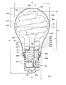
- FIG. 16 is a cross-sectional view of a lighting device according to a third embodiment.
- the illumination device 300 has a case 303 provided with a base 302 at one end (lower end in FIG. 16) in the height direction (tube axis direction), and the other end (upper end in FIG.
- the hot cathode fluorescent lamp 304 supported, the holding member 305 attached to the case 303 supporting one end side of the hot cathode fluorescent lamp 304, the hot cathode fluorescent lamp 304 and the periphery of the holding member 305 at the lower end side
- the bulb-type fluorescent lamp is provided with a globe 306 attached to the case 303, a base 302, and a lighting unit 307 housed inside the case 303.
- the rated power is formed in a size and appearance close to a general lighting light bulb such as a 40 [W] type, 60 [W] type, 100 [W] type incandescent light bulb, for example.
- the general lighting bulb is defined in JIS C 7501.
- the case 303, the holding member 305, and the glove 306 constitute a housing.
- the base 302 is, for example, an Edison type E26 type, and the upper end thereof is covered with one end of the case 303 and fixed by an adhesive or caulking.
- Case 303 is a cover integrally coupled with an inverted truncated conical portion whose diameter gradually decreases downward in FIG. 16 and a cylindrical portion hanging downward from the same, for example, with a heat resistant synthetic resin such as polybutylene terephthalate (PBT). It has a main body 303a, a base 302 is attached to one end (lower end in FIG. 16) of the cover main body 303a, and a cylinder which is an attachment end on the other end side (upper end in FIG. 16) of the cover main body 303a. An open mounting end 303b is formed. The lower cylindrical opening end of the holding member 305 is placed and fixed in the opening attachment end portion 303b.
- PBT polybutylene terephthalate
- the holding member 305 is formed of a heat-resistant synthetic resin such as PBT, for example, in a cylindrical shape with a lower end opening, and one end (lower end in FIG. 16) of the lower surface peripheral portion in the figure of the disk-shaped substrate portion 305a forming the lid.
- a cylindrical holder main body with an opening on the lower surface is formed by integrally linking a cylindrical cylindrical portion 305b projecting to the side).
- the lower end of the opening of the cylindrical portion 305b in FIG. 16 is placed on the cover body 303a and fixed by an adhesive or the like.
- the holding member 305 is a support recess for supporting the pair of electrode sealing end portions 304a and 304b of the hot cathode fluorescent lamp 304 on the substrate portion 305a, and a gap between the electrode sealing end portions 304a and 304b.
- a cylindrical projection 305c is provided so as to project inward and to restrict the radial displacement.
- the base plate portion 305a forms insertion holes 305d and 305e on the outer side of the cylindrical protrusion 305c, respectively, and a pair of electrode sealing end portions 304a of the hot cathode fluorescent lamp 304 are formed in these insertion holes 305d and 305e.
- Outer wires (not shown) of a short capillary and a long capillary projecting outward from 304 b are respectively inserted.
- the globe 306 is made of a transparent or light-diffusing synthetic resin (for example, polycarbonate, acrylic, polyethylene, etc.) having a thickness of, for example, 1 to 2 mm, for general lighting such as incandescent bulbs. It is formed in the shape of a smooth curved surface close to the shape of the glass bulb of a light bulb. That is, the globe 306 has a substantially spherically shaped spherical portion 306a and a substantially cylindrical diameter-reduced gradually smaller diameter than the diameter of the spherical portion 306a at the lower end of the spherical portion 306a in FIG.
- the portion 306 b is integrally coupled.
- the spherical portion 306 a has a maximum diameter portion 306 c indicating the maximum diameter of the globe 306.
- a reduced diameter opening end 306 d is formed at one end (lower end in FIG. 16) of the glove 306, and the edge of the opening end 306 d fits inside the opening attachment end 303 b of the case 303.
- they are bonded and fixed by an adhesive such as silicone resin or epoxy resin.
- the globe 306 is divided in two in the direction orthogonal to the central axis O of the hot cathode fluorescent lamp 304 and the illumination device 300, that is, the globe 306 is in the lateral direction (horizontal direction). That is, the globe 306 is divided into two in the vertical direction in FIG. 16 with the horizontal center line Oa of the largest outer diameter portion 304k of the hot cathode fluorescent lamp 304 as a horizontal dividing line, and a top glove 306e on the top end 306a side; It is divided into an underglobe 306f on the side of the reduced diameter portion 306b.
- the outer diameter of the maximum outer diameter portion 304 k of the hot cathode fluorescent lamp 304 is larger than the diameter reduction opening end 306 d of the globe 306. Therefore, the hot cathode fluorescent lamp 304 can not be inserted into the globe 306 from the open end portion 306 d.
- the heat cathode fluorescent lamp 304 is erected on the holding member 305,
- the outside of the cathode fluorescent lamp 304 is covered with the underglobe 306f and the topglobe 306e from above and below, respectively, and the butt surfaces of the open ends of both the gloves 306X1 and 6X2 are integrally fixed by ultrasonic welding. it can.
- the entire hot cathode fluorescent lamp 304 is formed by the pair of underglobes 306f and top gloves 306e. Can be coated.
- the entire outer surface of the glove 306 is similarly soluble in an organic solvent, and has a hydroxyl value of more than 5 [mg KOH / g], and a hydroxyl value and an acid value.
- Those containing a hydroxyl group-containing fluorocopolymer having a total amount exceeding 30 [mg KOH / g], and a curable fluorine-containing composition containing an acrylic resin further mixed therein are conventionally known methods such as brush, roller, air
- a glossy and translucent resin film (not shown) may be applied by coating and drying by a film forming method such as spray coating, airless spray, dip coating or the like and immersion coating.
- an organic solvent for diluting the composition that is the base material of the resin film it is possible to use mineral spirit, turpentine oil, petroleum naphtha, petroleum ether, petroleum benzine, petroleum benzine, etc.
- the degree of gloss of the resin film is preferably 60 degrees or more according to the test method based on JIS K-5600.
- the above-mentioned resin composition contains acrylic. It can be realized by appropriately selecting the amount.
- the thickness of the resin film after drying is preferably in the range of 10 [ ⁇ m] to 200 [ ⁇ m], and the deposition range is formed so as to overlap with the gap between the case 303 and the globe 306 It is preferable to do.
- the resin film also has an advantage of being able to significantly reduce an accidental drop accident of the glove 306.
- the hot cathode fluorescent lamp 304 has a spiral portion 304e as a bulging portion in the upper portion in FIG. 16 and a straight portion 304f in the lower portion, and these are integrally connected.
- the spiral portion 304e is formed by bending a straight circular tubular valve 304g having an outer diameter of, for example, 10 [mm] into two approximately equally divided portions, and using the folded portion 304h at the equally divided position as a top end It is formed by winding and molding into a double spiral shape.
- the bulb 304g is formed on its inner surface with a phosphor film of rare earth or the like over almost the entire length, and at both axial ends, a pair of electrodes 304i and 304j are respectively sealed to make the electrode sealing end 304a and 304b. Each is formed.
- the spiral portion 304 e extends from one of the electrode sealing ends of the bulb 304 g, for example, around the pivot axis O from 304 a to the folded back portion 304 h which is the top end in FIG.
- a double spiral shape having a pivoting portion of 1 and a second pivoting portion leading to the other electrode sealing end portion, eg, 304b while pivoting from the other end of the folded back portion 304h around the pivoting axis O, which is required
- a number for example, approximately three turns (number of turns). Therefore, the spiral portion 304 e is formed in a dense pitch portion where the spiral pitch is dense, and is formed in a long discharge path portion where the discharge path length is long.
- the folded portion 304h which is the top end of the helical portion 304e, is formed in a bulging portion whose valve diameter is larger than the diameters of the first and second pivoting portions, and the coldest portion is formed on this bulging portion. May be formed to form
- a coil electrode made of tungsten is used as the pair of electrodes 304i and 304j, and sealed in both ends of the bulb 304g in a state of being temporarily fixed by, for example, bead glass.
- a rare gas containing krypton gas as a buffer gas is enclosed in the glass bulb 304g, the total pressure of the rare gas is 600 [Pa] or more, and the proportion of krypton gas in the noble gas is 80 [Mol%] or more (preferably, 90 [mol%] or more). Further, the total pressure of the rare gas is preferably set to 1000 [Pa] or less.
- the helical portion 304 e as the bulging portion is accommodated in the spherical portion 306 a on the top end side having the largest diameter portion 306 c of the glove 306, and the helical diameter corresponds to the inner surface shape of the spherical portion 306 a of the glove 306.
- the diameter gradually increases from the folded back portion 304h toward the maximum diameter portion 306c, the spiral diameter is maximized at the maximum diameter portion 306c of the glove 306, and the diameter of the lower half portion of the spherical portion 306a of the glove 306 is reduced.
- the diameter of the spiral is gradually reduced to be integrally coupled to the upper end portion of the straight portion 304 f in FIG.
- the straight portion 304 f is the lower portion of the bulb 304 g on the side of the pair of electrode sealing end portions 304 a and 304 b in FIG.
- a pair of straight electrode sealing ends 304a and 304b are inserted in the supporting recess of the holding member 305, which are bent substantially at right angles to each other.
- the valve outer diameter C of the straight portion 304f is, for example, 7 [mm] to 9 [mm], and is smaller than the valve diameter D (for example, 8 [mm] to 10 [mm]) of the helical portion 304e. It is done.
- the straight portion 304f may be formed in a spiral shape by slightly curving the glass bulb 304g so as to align the turning direction of the spiral portion 304e.
- the vertical substrate 307a on which the lighting circuit pattern is formed is fitted and fixed in a pair of vertical grooves (not shown) on the inner surface of the holding member 305. That is, the holding member 305 has a pair of vertical grooves (not shown) opposed in the diameter direction formed in the axial direction of the holding member 305 on the inner surface of the cylindrical portion 305b. The width direction side edge part is inserted and fixed.
- the vertical substrate 307a is configured as a single-sided or double-sided substrate, and a plurality of electronic components 307b, which are lighting circuit components such as lead components such as electrolytic capacitors and chip components such as transistors, are mounted on the mounting surface.
- the bulb maximum outer diameter (helical outer diameter) of the hot cathode fluorescent lamp 304 is 54 [mm]
- the total height h1 of the lighting apparatus 300 is 109 [mm]
- the height h2 of the hot cathode fluorescent lamp 304 is 64 ⁇ 1 [mm] ]
- the height h3 of the maximum outer diameter portion 304k to the horizontal center line Oa is 38 mm
- the diameter r1 of the maximum diameter portion 306c of the globe 306 from the electrode sealing end of the hot cathode fluorescent lamp 304 is 60 mm
- the upper end outer diameter r2 is 32 [mm].
- the discharge path length between the pair of electrodes 304i and 304j is 360 [mm] to 610 [mm], which differs depending on the diameter of the valve 304g.
- the discharge path length is 476 mm
- the discharge path length is 374 mm.
- the outer diameter of the base 302 is 26 [mm], which is about 1.17 times the maximum outer diameter (30.5 [mm]) of the hot cathode fluorescent lamp.
- the lighting device 300 it is possible to obtain an appearance similar to a general lighting bulb.
- the helical portion 304e of the hot cathode fluorescent lamp 304 is accommodated in the relatively large-capacity spherical portion 306a including the largest diameter portion 306c of the globe 306, both the bulb diameter and the helical diameter are enlarged. be able to. For this reason, since the discharge path length of the helical portion 304 e can be extended, both the increase of the luminous flux in the helical portion 304 e and the improvement of the luminous efficiency can be achieved.
- the straight portion 304 f of the hot cathode fluorescent lamp 304 housed inside the narrow diameter-reduced portion 306 b of the glove 306 has a bulb outer diameter C smaller than the bulb outer diameter D of the spiral portion 304 e, the glove The gap around the straight portion 304f in the reduced diameter portion 306b can be increased. For this reason, it is possible to reduce the amount of light shielding in which light emitted from the spiral portion 304e and the straight portion 304f is blocked by the straight portion 304f itself. Thereby, the light emission efficiency can be improved.
- both the valve diameter and the helical diameter can be increased, so that the ease of forming the valve 304g into a helical shape can be improved by molding using a mold.
- the crack and distortion at the time of spiral molding can be reduced.
- both the mass productivity and the yield of the valve 304g having the spiral portion 304e can be improved.
- the bulb diameter of the spiral portion 304e that shares much of the discharge path length as the hot cathode fluorescent lamp 304 is large, the starting voltage and lamp voltage of the hot cathode fluorescent lamp 304 can be reduced. For this reason, it is not necessary to increase the output voltage of the lighting unit 307, and it is possible to lower the withstand voltage of the used parts, so cost reduction can be achieved, and further, enlargement of the lighting unit 307 is prevented. Or can be suppressed.
- the spiral portion 304e of the hot cathode fluorescent lamp 304 forms the bulb 304g in a spiral shape, light emitted inside the spiral portion 304e is shielded by the inner surface of the spiral bulb 304g itself.
- the straight portion 304f extends approximately parallel in the axial direction within the reduced diameter portion 306b of the globe 306, and the bulb outer diameter C is also reduced. Since it is thin, there are few portions shielded by the straight portion 304 f.
- the globe 306 is divided by the horizontal dividing line Oa along the direction perpendicular to the central axis (vertical axis) O. Therefore, when viewed from the top end side, The joint line of the dividing line joint can not be seen, and the appearance on the appearance can be improved, and the joint line shadow is hardly projected, and the appearance during lighting can also be improved.
- the dividing line joint When the joint surface of the horizontal dividing line Oa is fixed by ultrasonic welding or vibration welding, the dividing line joint is formed in the direction orthogonal to the axis of the globe 306, ie, in the horizontal direction (horizontal direction).
- the curvature on the line Oa is substantially constant all around.
- the distance between the ultrasonic or vibration applying position and the horizontal dividing line joint can be set to the entire circumference by simply rotating the lighting device 300 relative to the ultrasonic or vibration applying position about its central axis. Because the amount of irradiation (addition) of ultrasonic waves or vibrations applied to the horizontal dividing line joint can be made substantially uniform over the entire circumference. It is possible to reduce the variation in welding of the horizontal division line joint.
- both axial ends of the lighting device 300 that is, the base end of the lighting device 300 and the top end of the spherical portion 306a of the globe 306
- the pressure can be held so as to press inward in the direction, and the support thereof is facilitated, and in addition, the axial pressure distribution in the horizontal division line joint surface can be distributed substantially equally in the circumferential direction. For this reason, the dispersion
- this spiral type hot cathode fluorescent lamp 304 Even if the discharge path length is extended by forming the maximum outer diameter portion 304k of the bulging portion whose helical diameter is larger than the diameter of the diameter reduction opening end portion 306d of the globe 306, this hot cathode fluorescent lamp 304 can be used. It can be easily housed within the glove 306. For this reason, the efficiency of assembly workability of the lighting device 300 can be increased.
- the globe 306 is formed of resin
- the present invention is not limited to this, and may be made of, for example, glass.
- an inner surface of the glass glove 306 may be coated with an acrylic resin or a silicone resin containing an ultraviolet absorbing material.
- an ultraviolet absorber the combination of any one or more of titanium oxide (Ti), zinc oxide (Zn), iron oxide (Fe), and cerium oxide (Ce) is desirable.
- an ultraviolet absorbing material may be mixed with the light diffusing material and applied. According to this, it is possible to prevent or reduce discoloration or deterioration of the resin due to ultraviolet light, and to provide light diffusion.
- an ultraviolet absorber may be applied to the inner surface or the outer surface of the bulb 304g.
- a first protective film such as silica or alumina oxide is formed on the inner surface of the bulb of the hot cathode fluorescent lamp 304
- a second protective film is formed on the inner surface of the first protective film.
- a protective film may be formed, and a phosphor film may be further formed on the inner surface of the second protective film.
- the impurity that has reached the second protective film through the first protective film can suppress deposition on the phosphor film also by the second protective film, and the luminous efficiency and the luminous flux maintenance rate can be reduced. It can be improved.
- the first protective film preferably contains silica fine particles as a main component.
- the high density can suppress the precipitation of the impurities.
- the second protective film should contain at least one kind of fine particles of alumina (Al 2 O 3 ), calcium phosphate (Ca 2 P 2 O 7 ) or strontium phosphate (Sr 2 P 2 O 7 ) as a main component. Is preferred.
- the second protective film has a light reflection function, and the light emitted from the phosphor film can be reflected again to the phosphor film to cause the light to be emitted again, and the light emission efficiency can be improved.
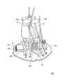
- FIG. 17 is a cross-sectional view showing a lighting device.
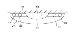
- a lighting device 400 according to the fourth embodiment includes a housing 410 and hot cathode fluorescent lamps 420 and 430 housed inside the housing 410.
- the housing 410 has a base portion 411 and a shield 412 covering the base portion 411.
- the base portion 411 is formed in a circular and thin appearance.
- a storage portion 413 having a storage space inside is formed at the center of the base portion 411.
- a high frequency lighting unit 414 including an inverter lighting circuit is disposed in the storage portion 413.
- the hot cathode fluorescent lamps 420 and 430 having a ring-shaped tube axis are arranged concentrically.
- the base portion 411 is provided with a socket holder (not shown) for feeding and holding the two annular hot cathode fluorescent lamps 420 and 430.
- the seed 412 is attached to cover the lower side and the side of the base 411.
- the sword 412 is a translucent white milk material, and is formed in a thin shape in which a large circular arc surface gradually protrudes downward, and an attachment portion (not shown) attached to the base portion 411 is formed in the peripheral portion. There is.
- FIG. 18 is a front view (main light emitting portion (opening) side) of the hot cathode fluorescent lamp having an annular tube axis
- FIG. 19 is an end face cut along the line AA in FIG. Is an enlarged cross-sectional view of FIG.
- the film thickness of each film or the like, the form of deposition, etc. are simplified and described for the sake of explanation, and a part is exaggerated and shown. Are different.
- the bulb 431 has an outer dimension substantially equal to that of “FCL 30” defined by JIS in which a cylindrical glass tube of soda lime glass is bent, and has an annular shape. That is, the present embodiment is a fluorescent lamp in which power saving is achieved by setting the reference lamp as the FCL 30.
- the tube outer diameter of the valve 431 is about 27 mm, and in the case of the FCL 30, 29 mm is a standard size, and the diameter is reduced by about 2 mm.
- Reference numeral 432 denotes a pair of mounts
- reference numeral 433 denotes a pair of sealing portions with the mounts 432 formed at the end of the valve 431, and the valve 431 and the mounts 432 constitute an airtight container.
- Each mount 432 crushes and seals a pair of lead wires 434 and an exhaust pipe (not shown) to a flared stem glass tube 433 and also has a tungsten wire wound between the lead wires 434.
- An electrode 435 formed of a coiled filament is connected.
- the mount 432 is a flare stem. Not limited to, a button stem or a bead stem may be used.
- the protective film 436 is coated on almost the entire inner surface of the bulb 431 to prevent blackening due to mercury or ultraviolet light and to prevent the fluorescent substance from being embedded in the glass.
- the protective film 436 is omitted.
- the protective film 436 is an aluminum oxide having an average particle diameter in the range of 0.01 ⁇ m to 0.1 ⁇ m, preferably in the range of 0.02 ⁇ m to 0.08 ⁇ m.
- at least one material selected from titanium oxide, zinc oxide, zirconium oxide, cerium oxide or yttrium oxide is in the range of 0.2 ⁇ m to 5.0 ⁇ m, preferably 0.
- the film thickness is in the range of 5 [ ⁇ m] to 3.0 [ ⁇ m] or less.
- the light reflection film 437 is translucent, is formed on the protective film 436, and reflects visible light.
- the main component is at least one material selected from aluminum oxide, titanium oxide, calcium pyrophosphate and strontium pyrophosphate and is within the range of 1 ⁇ m to 40 ⁇ m, preferably 3 ⁇ m to 30 ⁇ m.
- the film thickness is in the range of A light reflection film non-formed portion is formed at the opening on the lower side (FIG. 19) where the light reflection film substantially opposite to the semitransparent light reflection film 437 is not formed.
- titanium oxide, calcium pyrophosphate or strontium pyrophosphate or a mixture thereof is used as the main material of the light reflecting film 437, oxides of magnesium, calcium, strontium, barium and lead are formed on the surface of these main materials.
- oxides of magnesium, calcium, strontium, barium and lead are formed on the surface of these main materials.
- the average particle diameter of titanium oxide, calcium pyrophosphate or strontium pyrophosphate constituting the light reflection film 437 is in the range of 1.0 ⁇ m or more and 8.0 ⁇ m or less, preferably 3.0 ⁇ m or more. .0 [ ⁇ m] or less
- an oxide such as Mg, Ca, Sr, Ba, or Zn attached to the surface of titanium oxide or calcium pyrophosphate is 0.01 wt% or more with respect to titanium oxide, calcium pyrophosphate or strontium pyrophosphate.
- the adhesion can be made within the range of not more than 0 wt%, preferably within the range of not less than 0.02 wt% and not more than 3.0 wt%.
- the phosphor layer 438 is a fluorescent material such as a three-wavelength light emitting phosphor formed on the light reflecting film 437 and the protective film 436 where the light reflecting film 437 is not formed (opening 439) or calcium halophosphate (white phosphor). It is formed by applying body fine powder. Fine particles of magnesium oxide, calcium oxide, strontium oxide, barium oxide or zinc oxide may be attached to the phosphor constituting the phosphor layer 438. This adhesion also enables the phosphor layer 438 to suppress discoloration and mercury depletion caused by mercury and its compounds, and to obtain the same function and effect as described above. This oxide may be adhered to the surface as fine particles in the range of 5 [ ⁇ m] to 100 [ ⁇ m] or less in average particle diameter, or may be coated and adhered to the surface as a homogeneous film.
- a fluorescent material such as a three-wavelength light emitting phosphor formed on the light reflecting film 437 and the protective film 436 where the light reflecting film 437 is not
- the protective film 436 is formed by applying a fine powder material mainly composed of aluminum oxide having an average particle diameter of about 0.02 ⁇ m, and is formed with a film thickness of about 1 ⁇ m.
- a fine powder material mainly composed of calcium pyrophosphate having an average particle diameter of about 5 [ ⁇ m] is used as the light reflection film 437.
- the light reflecting film 437 has a film thickness of about 25 [C] at a predetermined angle on the inner surface of the bulb 431, for example, in the range of an opening angle of about 150 [degree] in the circumferential direction (about 75 [.degree.
- the film thickness of the first reflective film 437a which is a thick film, is gradually reduced gradually from about 25 ⁇ m of the thick film portion on both sides of the reflective film 437a.
- the second reflection film (thin film portion) 437b which is 0 [.mu.m], is formed in the range of about 25 [.degree.]
- Each of the opening angle, and the first reflection film 437a and the second reflection film 437b The combined light reflecting film 437 acts as a light reflecting film 437 in the range of an opening angle of about 200 [°] (each about 100 [°] from the vertical center line), substantially having a film thickness of 5 ⁇ m or more.
- the opening angle is about 180 [°] (about 90 [°] each side from the vertical center line).
- the phosphor layer 438 may be, for example, europium-activated barium calcium calcium strontium halophosphate (blue phosphor), cerium / terbium-activated lanthanum phosphate (green phosphor), and europium-activated yttrium oxide (red phosphor). It consists of what was formed by mix-coating the fine powder of three types of fluorescent substance.
- a rare gas is sealed as a buffer gas.
- the rare gas contains krypton gas, the total pressure of the rare gas is 600 [Pa] or more, and the ratio of krypton gas in the rare gas is 80 [mol%] or more (preferably 90). [Mol%] or more). Further, the total pressure of the rare gas is preferably set to 1000 [Pa] or less.
- An amalgam may be enclosed in the valve 431.
- the amalgam is contained in a stem sealed at the end of the valve 431 or in a thin tube provided on the stem.
- the amalgam is fixed or stored in any of these positions by means such as melting, mechanical holding, and the like.
- the amalgam may be movably accommodated in the valve 431.
- Amalgam is selected from bismuth (Bi), indium (In), lead (Pb), tin (Sn), zinc (Zn), cadmium (Cd), silver (Ag), etc., which are substances that form an alloy with mercury. It is an alloy of mercury and at least one of them.
- an alloy of bismuth, indium and mercury, an alloy of bismuth, indium, lead and mercury, an alloy of bismuth, tin and mercury, and the like are applicable.
- amalgam such as zinc-mercury may be similarly enclosed for quantitative inclusion of mercury without the purpose of mercury vapor pressure control.
- the amalgam may be in any shape such as pellet, column, plate and the like.
- the base 440 is G10 q-shaped having a pin terminal 441, and is fixed by bridging the sealing portions 442 at both ends of the bent valve 431.
- the light emission from the outer peripheral surface across the bulb 431 from the hot cathode fluorescent lamp 420 is not uniform, and the first reflective film (having a high light reflectivity in the range of 180 [°] or more in the circumferential direction of the annular bulb 431
- a light reflection film 437 having a film portion 437a and a second reflection film (thin film portion) 437b does not form the light reflection film 437 in the remaining portion; Since the non-forming portion) 439 is substantially directly opposed, the light intensity (light quantity) emitted from the lower opening (the light-reflecting film non-forming portion) 439 along the axial direction of the bulb 431
- the light reflected by the reflection films 437a and 437b and directed to the opening (non-light reflection film-formed area) 439 is also added (strong), that is, bright.
- light is emitted from the upper side and the side side through the first reflection film (thick film portion) 437a and the second reflection film (thin film portion) 437b in which the semitransparent light reflection film 437 is formed. Be done.
- These semitransparent light reflection films 437 have high light reflectance and low light transmittance, and the amount of light emitted from the first reflection film (thick film portion) 437a as a thick film is an opening (no light reflection film formation).
- the second reflection film (thin film part) 437b connected to the first reflection film (thick film part) 437a is much weaker than the first reflection film (thick film part) 437a.
- the film thickness is gradually changed since it is a thin film, the amount of light is larger than that of the first reflection film (thick film portion) 437a, and it is possible to generate a gradually changing radiation light amount.
- the second reflection film (thin film portion) 437b formed between the first reflection film (thick film portion) 437a and the opening (light reflection film non-formed portion) 439 has a first emitted light amount. Radiant light with a gradual change in light intensity and brightness by buffering light and dark differences between the two with a gradient connecting the reflection film (thick film portion) 437a and the opening (non-light reflection film formation portion) 439 Can be generated.
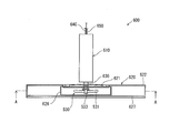
- FIG. 20 is a cross-sectional side view showing the lighting apparatus according to the fifth embodiment
- FIG. 21 is a front view showing the inside of the lamp body.
- a lighting device 500 according to the fifth embodiment includes a lighting device 520 and a spiral hot cathode fluorescent lamp 530 in a housing 510.
- a mounting device 550 is provided in the housing 510, and can be mounted on a ceiling, a wall, or the like.
- the casing 510 is a rectangular flat bottom plate 511, and four wall plates made of, for example, polybutylene terephthalate resin and having excellent heat resistance that can be fitted to the outer periphery of the four sides of the bottom plate 511. And an inner space 513 is formed inside the wall plate 512.
- a resin panel 514 such as a milk white made of acrylic resin and the like having a light diffusion family for making the lamp image (brightness balance) uniform is provided.
- a cover 515 is composed of the resin 512 and the resin panel 514.
- a rectangular notch 516 is provided at the center of the bottom plate 511.
- the attachment device 550 is attached to the bottom plate 511 through the notch 516.
- a lighting device (electronic ballast) 520 is attached to the upper surface of the bottom plate 511.
- a pair of lamp support springs 517 for holding the spiral hot cathode fluorescent lamp 530 and a socket 518 are mounted close to each other on the side of the lighting device 520 (downward in FIG. 20).
- the socket 518 is preferably as far away from the center of the spiral hot cathode fluorescent lamp 530 as possible to prevent it from becoming hot.
- the attachment device 550 is rotatably supported about a connecting shaft 551 attached to the housing 510.
- One end of an L-shaped movable arm 552 is integrally attached to the connecting shaft 551 by, for example, an aluminum die-cast pipe.
- the movable arm 552 can be accommodated in the notch 516.
- a rotary support 554 is attached to the other end of the movable arm 552 via a decorative nut 553, and a plug 555 is attached to the tip of the rotary support 554.
- the plug 555 is movable and electrically conductive along, for example, a wiring duct (not shown) provided on a ceiling surface which is a mounting surface.
- the lighting device 520 supplies power to the spiral hot cathode fluorescent lamp 530 to light it.
- FIG. 22 is a plan view of a spiral-shaped hot cathode fluorescent lamp
- FIG. 23 is a front view of the spiral-shaped hot cathode fluorescent lamp.
- the spiral-shaped hot cathode fluorescent lamp 530 comprises an arc tube 531 having a single discharge path inside, and a holder 533 for holding the arc tube 531. Note that, although described later, a cap 534 for power supply is attached to the holder 533.
- the light emitting tube 531 has two pivoting portions for pivoting about an imaginary axis from the middle portion of the glass tube to both ends or to the front of the both ends, and the axial centers of the glass tubes in the two pivoting portions
- the valve 535 and the pair of ends 536 of the valve 535 are airtightly sealed, respectively, in such a manner that one plane orthogonal to the virtual axis is formed away from the virtual axis as moving from the middle portion to the end side.
- the valve 535 is sealed with mercury (for example, 5 mg) and a rare gas containing krypton gas as a buffer gas.
- the total pressure of the rare gas is 600 [Pa] or more, and the proportion of krypton gas in the rare gas is 80 [mol%] or more (preferably 90 [mol%] or more). Further, the total pressure of the rare gas is preferably set to 1000 [Pa] or less.
- the form of mercury enclosed in the bulb 535 may be a single form, or may be an amalgam form such as zinc mercury, tin mercury, or bismuth indium mercury.
- the glass tube constituting the valve 535 has two pivoting portions 537 which pivot around the imaginary axis A, and an intermediate portion 538 sandwiched between the pivoting portions 537.
- the axial center of the glass tube in the turning portion 537 is in a substantially one plane substantially orthogonal to the virtual axis A, and takes a trajectory away from the virtual axis A as it moves from the intermediate portion 538 to the end of the glass tube There is. That is, the turning portion 537 has a planar spiral shape.
- a bulging portion 539 that bulges in one of the virtual axial directions is formed at a position where the virtual axis A in the valve 535 passes, that is, at the center of the middle portion 538 of the glass tube.
- the bulging portion 539 is a so-called coldest spot which becomes the coldest spot when the spiral-shaped hot cathode fluorescent lamp 530 is lit, and the temperature in the coldest spot causes the inside of the bulb 535 at the time of lighting.
- the vapor pressure of mercury is defined.
- the glass tube for example, barium strontium silicate glass (lead free glass) is used, and its cross-sectional shape is, for example, substantially circular.
- the cross-sectional shape of a glass tube is not limited to circular shape, For example, substantially elliptical shape may be sufficient.
- the bulb 535 is formed in a flat spiral shape by curving a softened glass tube, and the cross-sectional shape of the glass tube after molding is not a perfect circle but a slight deformation.
- this valve 535 When this valve 535 is viewed from the irradiation surface side, a gap is generated between the two turning portions 537 in a direction orthogonal to the imaginary axis A (hereinafter, this direction is referred to as “radial direction”). Since the cross section of the glass tube in the turning portion 537 has a circular shape, the clearance on the line connecting the axial centers of the glass tube in the turning portion 537 is minimized.
- the gap between the adjacent turning portions 537 is such that the portion near the end 536 of the valve 535 is larger than the gap between the other turning portions 537. This is to prevent the pivoting portion adjacent to the end 536 from deforming when the end 536 is heated when sealing the electrode to the end 536 and close to the end 536 of the valve 535
- the gap in a range excluding a portion (for example, from the end portion 536 to the middle portion 538 side, up to about 45 degrees returned along the axis of the glass tube) is large.
- This phosphor includes three types of red, green and blue light emission, and includes, for example, Y 2 O 3 : Eu, LaPO 4 : Ce, Tb and BaMg 2 Al 16 O 27 : Eu, Mn phosphor.
- the electrode is sealed, and a buffer gas or the like is enclosed inside the bulb 535 to complete the luminous tube 531.
- a buffer gas or the like is enclosed inside the bulb 535 to complete the luminous tube 531.
- portions corresponding to the end portion 536 and the middle portion 538 of the valve 535 are used as they are as the end portion 536 and the middle portion 538 of the luminous tube 531.
- the radial direction of the bulb 535 is also used as the radial direction when the light emitting tube 531 is described.
- the light emitting tube 531 is attached to the holder 533 such that the bulging portion 539 side is the front side (irradiated surface).
- the holder 533 includes a holding member 540 for holding the end 536 of the light emitting tube 531 and a pair of mouthpieces 534 for supplying power to the light emitting tube 531.
- the base 534 is a type provided with two power supply connection pins 541.
- the holding member 540 includes a base 542 having a rectangular shape elongated in a direction connecting the end portions 536 of the light emitting tube 531 and raised portions 543 formed at both ends in the longitudinal direction of the base 542.
- the insertion hole for inserting the end part 536 of the light emission tube 531 is formed.
- the illumination device 500 since the lighting device 520 is disposed adjacent to the spiral hot cathode fluorescent lamp 530, the illumination device 500 can be made compact. Further, since the mounting device 550 is mounted at a position close to the lighting device 520, when the power supply line is wired along the mounting device 550, the wiring can be shortened and simplified. Furthermore, since the illumination device 500 is attached by the movable arm 552, the relative angle of the movable arm 552 with respect to the illumination device 500 can be adjusted to adjust the attachment angle of the illumination device 500.
- FIG. 24 is a cross-sectional front view showing a lighting apparatus according to a sixth embodiment
- FIG. 25 is a cross-sectional view taken along the line AA in FIG. As shown in FIG.
- a lighting apparatus 600 includes a spiral hot cathode fluorescent lamp 530 similar to the spiral hot cathode fluorescent lamp 530 according to the fifth embodiment, and a spiral hot cathode fluorescent lamp.
- the lighting device 610 for supplying power to the lamp 530 is provided, and the lighting device 610 is provided on the upper side of a housing 620 in which the spiral hot cathode fluorescent lamp 530 is mounted. That is, lighting device 610 is arranged on the upper side (upper side in FIG. 24) with respect to housing 620, and the longitudinal direction of lighting device 610 is arranged along the hanging direction (vertical direction in FIG. 24). doing.
- a connecting member 630 is provided between the housing 620 and the lighting device 610.
- the lighting wire 610 is hung downward from a mounting device (not shown) attached to the ceiling to suspend the lighting device 610, and the lower side of the lighting device 610 is housed via the connection member 630.
- the body 620 is suspended.
- the power supply line 650 connected to the mounting device is dropped downward and connected to the lighting device 610, and the mounting device is connected to the power supply line wired to the ceiling to supply power to the lighting device 610. ing.
- a pipe-shaped connecting member 630 is attached downward at the center of the lower surface of the lighting device 610.
- the connecting member 630 has a strength to suspend the housing 620 from the lighting device 610 and has a space for wiring a lamp line (not shown) for supplying power to the spiral hot cathode fluorescent lamp 530 inside. There is. Further, the width dimension and the outer diameter of the connecting member 630 as viewed from the side are set to be smaller than the side view width dimension of the lighting device 610 as well as the housing 620.
- the housing 620 has a substantially circular thin box shape, and a disc-shaped aluminum die-cast lamp main body 621 is integrally provided on the lower end surface of the connection member 630.
- a bottomed cylindrical upper cover 622 is mounted on the lamp main body 621 with the opening facing downward.
- the upper cover 622 is made of, for example, polycarbonate resin, has translucency, and is configured to irradiate the light from the spiral hot cathode fluorescent lamp 530 sideways and upward. As shown in FIG.
- a reflecting plate 623 made of, for example, a white-painted steel plate is attached to the lower surface of the lamp body 621, and a pair of lamp support springs 624 and a pair of sockets 625 are attached to the lower surface of the reflecting plate 623. Are mounted close to each other and downward.
- a translucent bottomed cylindrical main body cover 626 made of polycarbonate resin having an open upper portion, and a light reducing member covering the opening of the upper cover 622 and facing the spiral hot cathode fluorescent lamp 530 And a lower cover 627.
- the main body cover 626 and the lower cover 627 can be attached to and detached from the lamp main body 621 when replacing the spiral hot cathode fluorescent lamp 530 or the like.
- the peripheral wall of the main body cover 626 can be made of a material having a property of diffusing light.
- the lower cover 627 for example, a panel made of a coated steel plate which does not transmit light, a milky white acrylic plate, a mesh or the like can be used.
- the main body cover 626 has a size that includes the lamp main body 621 inside, and includes the spiral hot cathode fluorescent lamp 530.
- the main body cover 626 includes the spiral hot cathode fluorescent light in the lower cover 627. It is difficult for the lamp image of the lamp 530 to appear.
- the main body cover 626 and the lower cover 627 may be integrated. Also, if the upper cover 622 and the lower cover 627 are made of a light-shielding coated steel plate, a horizontal interval is formed between the upper cover 622 and the lower cover 627, and light is emitted from this interval. Good.
- the total pressure of the enclosed noble gas in the bulb 535 is 600 [Pa] or more, and the ratio of krypton gas in the enclosed noble gas is 80 [mol%] or more Therefore, as in the case of the backlight according to the first embodiment, the efficiency is higher than that of a lighting device equipped with a conventional hot cathode fluorescent lamp.
Landscapes
- Planar Illumination Modules (AREA)
- Discharge Lamp (AREA)
Abstract
Priority Applications (2)
| Application Number | Priority Date | Filing Date | Title |
|---|---|---|---|
| JP2009549989A JPWO2009090881A1 (ja) | 2008-01-18 | 2009-01-16 | バックライト及び照明装置 |
| CN2009801095167A CN101978465A (zh) | 2008-01-18 | 2009-01-16 | 背光源和照明装置 |
Applications Claiming Priority (2)
| Application Number | Priority Date | Filing Date | Title |
|---|---|---|---|
| JP2008-009127 | 2008-01-18 | ||
| JP2008009127 | 2008-01-18 |
Publications (1)
| Publication Number | Publication Date |
|---|---|
| WO2009090881A1 true WO2009090881A1 (fr) | 2009-07-23 |
Family
ID=40885273
Family Applications (1)
| Application Number | Title | Priority Date | Filing Date |
|---|---|---|---|
| PCT/JP2009/000144 Ceased WO2009090881A1 (fr) | 2008-01-18 | 2009-01-16 | Dispositif de rétro-éclairage et d'éclairage |
Country Status (5)
| Country | Link |
|---|---|
| JP (1) | JPWO2009090881A1 (fr) |
| KR (1) | KR20100113079A (fr) |
| CN (1) | CN101978465A (fr) |
| TW (1) | TW200935488A (fr) |
| WO (1) | WO2009090881A1 (fr) |
Cited By (2)
| Publication number | Priority date | Publication date | Assignee | Title |
|---|---|---|---|---|
| JP2010009884A (ja) * | 2008-06-25 | 2010-01-14 | Panasonic Electric Works Co Ltd | 平面らせん形蛍光ランプおよび照明器具 |
| US7708429B2 (en) | 2006-07-21 | 2010-05-04 | Gregory Kennedy | Illuminated document display system |
Families Citing this family (1)
| Publication number | Priority date | Publication date | Assignee | Title |
|---|---|---|---|---|
| JP6353698B2 (ja) * | 2014-05-16 | 2018-07-04 | 明拓工業株式会社 | 発光パネル |
Citations (8)
| Publication number | Priority date | Publication date | Assignee | Title |
|---|---|---|---|---|
| JPS60151948A (ja) * | 1984-01-19 | 1985-08-10 | Ushio Inc | 小型螢光燈 |
| JPS6277858U (fr) * | 1985-11-06 | 1987-05-19 | ||
| JPH09265901A (ja) * | 1996-03-28 | 1997-10-07 | Toshiba Lighting & Technol Corp | 環形蛍光ランプおよび照明装置 |
| JPH103879A (ja) * | 1996-06-12 | 1998-01-06 | Tdk Corp | セラミック陰極蛍光放電ランプ |
| JP2005158467A (ja) * | 2003-11-25 | 2005-06-16 | Matsushita Electric Ind Co Ltd | 発光管の製造方法、発光管、低圧水銀ランプ及び照明装置 |
| JP2006049013A (ja) * | 2004-08-02 | 2006-02-16 | Matsushita Electric Ind Co Ltd | 発光管及び低圧水銀放電ランプ |
| WO2007032320A1 (fr) * | 2005-09-13 | 2007-03-22 | Matsushita Electric Industrial Co., Ltd. | Lampe a decharge a cathode chaude, unite de lampe et dispositif d'affichage |
| WO2007032319A1 (fr) * | 2005-09-13 | 2007-03-22 | Matsushita Electric Industrial Co., Ltd. | Lampe a decharge a cathode chaude, unite de lampe et appareil d'affichage |
-
2009
- 2009-01-16 WO PCT/JP2009/000144 patent/WO2009090881A1/fr not_active Ceased
- 2009-01-16 CN CN2009801095167A patent/CN101978465A/zh active Pending
- 2009-01-16 KR KR1020107015124A patent/KR20100113079A/ko not_active Withdrawn
- 2009-01-16 JP JP2009549989A patent/JPWO2009090881A1/ja not_active Withdrawn
- 2009-01-17 TW TW98101808A patent/TW200935488A/zh unknown
Patent Citations (8)
| Publication number | Priority date | Publication date | Assignee | Title |
|---|---|---|---|---|
| JPS60151948A (ja) * | 1984-01-19 | 1985-08-10 | Ushio Inc | 小型螢光燈 |
| JPS6277858U (fr) * | 1985-11-06 | 1987-05-19 | ||
| JPH09265901A (ja) * | 1996-03-28 | 1997-10-07 | Toshiba Lighting & Technol Corp | 環形蛍光ランプおよび照明装置 |
| JPH103879A (ja) * | 1996-06-12 | 1998-01-06 | Tdk Corp | セラミック陰極蛍光放電ランプ |
| JP2005158467A (ja) * | 2003-11-25 | 2005-06-16 | Matsushita Electric Ind Co Ltd | 発光管の製造方法、発光管、低圧水銀ランプ及び照明装置 |
| JP2006049013A (ja) * | 2004-08-02 | 2006-02-16 | Matsushita Electric Ind Co Ltd | 発光管及び低圧水銀放電ランプ |
| WO2007032320A1 (fr) * | 2005-09-13 | 2007-03-22 | Matsushita Electric Industrial Co., Ltd. | Lampe a decharge a cathode chaude, unite de lampe et dispositif d'affichage |
| WO2007032319A1 (fr) * | 2005-09-13 | 2007-03-22 | Matsushita Electric Industrial Co., Ltd. | Lampe a decharge a cathode chaude, unite de lampe et appareil d'affichage |
Cited By (2)
| Publication number | Priority date | Publication date | Assignee | Title |
|---|---|---|---|---|
| US7708429B2 (en) | 2006-07-21 | 2010-05-04 | Gregory Kennedy | Illuminated document display system |
| JP2010009884A (ja) * | 2008-06-25 | 2010-01-14 | Panasonic Electric Works Co Ltd | 平面らせん形蛍光ランプおよび照明器具 |
Also Published As
| Publication number | Publication date |
|---|---|
| CN101978465A (zh) | 2011-02-16 |
| JPWO2009090881A1 (ja) | 2011-05-26 |
| TW200935488A (en) | 2009-08-16 |
| KR20100113079A (ko) | 2010-10-20 |
Similar Documents
| Publication | Publication Date | Title |
|---|---|---|
| US7116043B2 (en) | Compact self-ballasted fluorescent lamp with improved rising characteristics | |
| US7411350B2 (en) | Small arc tube, low-pressure mercury lamp, lighting apparatus, mandrel for forming the arc tube, and production method of the arc tube | |
| JPWO2009090881A1 (ja) | バックライト及び照明装置 | |
| US6984926B2 (en) | Compact self-ballasted fluorescent lamp resistant to heat deformation | |
| JP4709859B2 (ja) | 放電ランプ及び照明装置 | |
| JP4130795B2 (ja) | 発光管、放電ランプ | |
| WO2009087735A1 (fr) | Lampe à décharge et matériel d'éclairage | |
| TWI330381B (fr) | ||
| JP3653552B2 (ja) | 冷陰極蛍光ランプおよび照明装置 | |
| JP2008292581A (ja) | 直下型液晶ディスプレイ用バックライト | |
| JP2005347236A (ja) | 電球形蛍光ランプおよび照明装置 | |
| JP2003187750A (ja) | 蛍光ランプおよび照明装置 | |
| JP4304605B2 (ja) | 電球形蛍光ランプおよび照明装置 | |
| JP2008262821A (ja) | 熱陰極蛍光ランプを備えたバックライト | |
| CN101263579A (zh) | 热阴极型放电灯、灯单元以及显示装置 | |
| JP4755170B2 (ja) | 発光管、放電ランプ及び発光管の製造方法 | |
| JP2008204795A (ja) | 熱陰極蛍光ランプを備えたバックライト | |
| JP2007018737A (ja) | 蛍光ランプ及びバックライト装置 | |
| JP2006147289A (ja) | 冷陰極蛍光ランプ及びバックライト装置 | |
| JP2010282770A (ja) | 電極構造体、電極構造体の製造方法、冷陰極放電ランプ、照明装置および画像表示装置 | |
| JP2009129582A (ja) | バックライト | |
| JP2008204796A (ja) | 熱陰極蛍光ランプを備えたバックライト | |
| CN101669190A (zh) | 长寿命热阴极荧光灯、具备该热阴极荧光灯的背光灯或照明装置及其启动方法 | |
| CN101668983A (zh) | 直下型液晶显示器用背光源 | |
| JP2008262820A (ja) | 熱陰極蛍光ランプを備えたバックライト |
Legal Events
| Date | Code | Title | Description |
|---|---|---|---|
| WWE | Wipo information: entry into national phase |
Ref document number: 200980109516.7 Country of ref document: CN |
|
| 121 | Ep: the epo has been informed by wipo that ep was designated in this application |
Ref document number: 09702149 Country of ref document: EP Kind code of ref document: A1 |
|
| ENP | Entry into the national phase |
Ref document number: 2009549989 Country of ref document: JP Kind code of ref document: A |
|
| ENP | Entry into the national phase |
Ref document number: 20107015124 Country of ref document: KR Kind code of ref document: A |
|
| NENP | Non-entry into the national phase |
Ref country code: DE |
|
| 122 | Ep: pct application non-entry in european phase |
Ref document number: 09702149 Country of ref document: EP Kind code of ref document: A1 |