WO2009090954A1 - Siège - Google Patents
Siège Download PDFInfo
- Publication number
- WO2009090954A1 WO2009090954A1 PCT/JP2009/050366 JP2009050366W WO2009090954A1 WO 2009090954 A1 WO2009090954 A1 WO 2009090954A1 JP 2009050366 W JP2009050366 W JP 2009050366W WO 2009090954 A1 WO2009090954 A1 WO 2009090954A1
- Authority
- WO
- WIPO (PCT)
- Prior art keywords
- seat
- pelvis
- pelvic
- displacement
- seated occupant
- Prior art date
- Legal status (The legal status is an assumption and is not a legal conclusion. Google has not performed a legal analysis and makes no representation as to the accuracy of the status listed.)
- Ceased
Links
Images


Classifications
-
- B—PERFORMING OPERATIONS; TRANSPORTING
- B60—VEHICLES IN GENERAL
- B60N—SEATS SPECIALLY ADAPTED FOR VEHICLES; VEHICLE PASSENGER ACCOMMODATION NOT OTHERWISE PROVIDED FOR
- B60N2/00—Seats specially adapted for vehicles; Arrangement or mounting of seats in vehicles
- B60N2/02—Seats specially adapted for vehicles; Arrangement or mounting of seats in vehicles the seat or part thereof being movable, e.g. adjustable
- B60N2/0224—Non-manual adjustments, e.g. with electrical operation
- B60N2/02246—Electric motors therefor
-
- B—PERFORMING OPERATIONS; TRANSPORTING
- B60—VEHICLES IN GENERAL
- B60N—SEATS SPECIALLY ADAPTED FOR VEHICLES; VEHICLE PASSENGER ACCOMMODATION NOT OTHERWISE PROVIDED FOR
- B60N2/00—Seats specially adapted for vehicles; Arrangement or mounting of seats in vehicles
- B60N2/90—Details or parts not otherwise provided for
- B60N2/976—Details or parts not otherwise provided for massaging systems
-
- B—PERFORMING OPERATIONS; TRANSPORTING
- B60—VEHICLES IN GENERAL
- B60N—SEATS SPECIALLY ADAPTED FOR VEHICLES; VEHICLE PASSENGER ACCOMMODATION NOT OTHERWISE PROVIDED FOR
- B60N2/00—Seats specially adapted for vehicles; Arrangement or mounting of seats in vehicles
- B60N2/002—Seats provided with an occupancy detection means mounted therein or thereon
- B60N2/0021—Seats provided with an occupancy detection means mounted therein or thereon characterised by the type of sensor or measurement
- B60N2/0024—Seats provided with an occupancy detection means mounted therein or thereon characterised by the type of sensor or measurement for identifying, categorising or investigation of the occupant or object on the seat
- B60N2/0027—Seats provided with an occupancy detection means mounted therein or thereon characterised by the type of sensor or measurement for identifying, categorising or investigation of the occupant or object on the seat for detecting the position of the occupant or of occupant's body part
- B60N2/0028—Seats provided with an occupancy detection means mounted therein or thereon characterised by the type of sensor or measurement for identifying, categorising or investigation of the occupant or object on the seat for detecting the position of the occupant or of occupant's body part of a body part, e.g. of an arm or a leg
-
- B—PERFORMING OPERATIONS; TRANSPORTING
- B60—VEHICLES IN GENERAL
- B60N—SEATS SPECIALLY ADAPTED FOR VEHICLES; VEHICLE PASSENGER ACCOMMODATION NOT OTHERWISE PROVIDED FOR
- B60N2/00—Seats specially adapted for vehicles; Arrangement or mounting of seats in vehicles
- B60N2/002—Seats provided with an occupancy detection means mounted therein or thereon
- B60N2/0021—Seats provided with an occupancy detection means mounted therein or thereon characterised by the type of sensor or measurement
- B60N2/003—Seats provided with an occupancy detection means mounted therein or thereon characterised by the type of sensor or measurement characterised by the sensor mounting location in or on the seat
- B60N2/0034—Seats provided with an occupancy detection means mounted therein or thereon characterised by the type of sensor or measurement characterised by the sensor mounting location in or on the seat in, under or on the seat cover
-
- B—PERFORMING OPERATIONS; TRANSPORTING
- B60—VEHICLES IN GENERAL
- B60N—SEATS SPECIALLY ADAPTED FOR VEHICLES; VEHICLE PASSENGER ACCOMMODATION NOT OTHERWISE PROVIDED FOR
- B60N2/00—Seats specially adapted for vehicles; Arrangement or mounting of seats in vehicles
- B60N2/02—Seats specially adapted for vehicles; Arrangement or mounting of seats in vehicles the seat or part thereof being movable, e.g. adjustable
- B60N2/0224—Non-manual adjustments, e.g. with electrical operation
- B60N2/0244—Non-manual adjustments, e.g. with electrical operation with logic circuits
- B60N2/0268—Non-manual adjustments, e.g. with electrical operation with logic circuits using sensors or detectors for adapting the seat or seat part, e.g. to the position of an occupant
-
- B—PERFORMING OPERATIONS; TRANSPORTING
- B60—VEHICLES IN GENERAL
- B60N—SEATS SPECIALLY ADAPTED FOR VEHICLES; VEHICLE PASSENGER ACCOMMODATION NOT OTHERWISE PROVIDED FOR
- B60N2/00—Seats specially adapted for vehicles; Arrangement or mounting of seats in vehicles
- B60N2/02—Seats specially adapted for vehicles; Arrangement or mounting of seats in vehicles the seat or part thereof being movable, e.g. adjustable
- B60N2/0224—Non-manual adjustments, e.g. with electrical operation
- B60N2/0244—Non-manual adjustments, e.g. with electrical operation with logic circuits
- B60N2/0273—Non-manual adjustments, e.g. with electrical operation with logic circuits taking into account user data, e.g. knee height or physical state
-
- B—PERFORMING OPERATIONS; TRANSPORTING
- B60—VEHICLES IN GENERAL
- B60N—SEATS SPECIALLY ADAPTED FOR VEHICLES; VEHICLE PASSENGER ACCOMMODATION NOT OTHERWISE PROVIDED FOR
- B60N2/00—Seats specially adapted for vehicles; Arrangement or mounting of seats in vehicles
- B60N2/02—Seats specially adapted for vehicles; Arrangement or mounting of seats in vehicles the seat or part thereof being movable, e.g. adjustable
- B60N2/0284—Adjustable seat-cushion length
-
- B—PERFORMING OPERATIONS; TRANSPORTING
- B60—VEHICLES IN GENERAL
- B60N—SEATS SPECIALLY ADAPTED FOR VEHICLES; VEHICLE PASSENGER ACCOMMODATION NOT OTHERWISE PROVIDED FOR
- B60N2/00—Seats specially adapted for vehicles; Arrangement or mounting of seats in vehicles
- B60N2/02—Seats specially adapted for vehicles; Arrangement or mounting of seats in vehicles the seat or part thereof being movable, e.g. adjustable
- B60N2/22—Seats specially adapted for vehicles; Arrangement or mounting of seats in vehicles the seat or part thereof being movable, e.g. adjustable the back-rest being adjustable
- B60N2002/2204—Adjustable back-rest height or length
-
- B—PERFORMING OPERATIONS; TRANSPORTING
- B60—VEHICLES IN GENERAL
- B60N—SEATS SPECIALLY ADAPTED FOR VEHICLES; VEHICLE PASSENGER ACCOMMODATION NOT OTHERWISE PROVIDED FOR
- B60N2205/00—General mechanical or structural details
- B60N2205/30—Seat or seat parts characterised by comprising plural parts or pieces
-
- B—PERFORMING OPERATIONS; TRANSPORTING
- B60—VEHICLES IN GENERAL
- B60N—SEATS SPECIALLY ADAPTED FOR VEHICLES; VEHICLE PASSENGER ACCOMMODATION NOT OTHERWISE PROVIDED FOR
- B60N2210/00—Sensor types, e.g. for passenger detection systems or for controlling seats
- B60N2210/40—Force or pressure sensors
Definitions
- the present invention relates to a seat, particularly a seat provided with a seat cushion and a seat back.
- the seat part of the automobile seat has a seat part reinforcing frame that carries a suspension grid, and a vibration part that generates a vibration motion in the seat part, While moving the pelvis to the correct position on the back, it creates an alternating massage effect on the lower side of the thigh and a small movement of the lower spine.
- the seat described in Patent Document 2 includes a lumbar support device that supports the lumbar portion of the seated person, a pelvis support device that supports the pelvis portion, a detection unit that detects rotation of the pelvis, and a control unit. It is designed to maintain a comfortable sitting posture.
- JP 2001-353039 A Japanese Utility Model Publication No. 3-19344
- the seated person may be greatly out of the sitting posture after sitting on the seat for a long time. That is, the pelvis may be displaced and the upper body supported by the seat back may also be displaced.
- the present invention has an object to obtain a seat that can reduce the collapse of the sitting posture over the whole body in consideration of the above facts.
- the seat according to the first aspect of the present invention is provided in a seat cushion, provided in a seat back and a pelvis detection unit for detecting a longitudinal displacement of the pelvis relative to the seat cushion seating surface of a seated occupant, and the seat A thorax detection unit for detecting a vertical displacement of the rib cage relative to the seat back occupant contact surface of the seated occupant, a pelvis moving unit for moving the position of the pelvis of the seated occupant in the front-rear direction, and the seat seated occupant A thoracic movement unit for moving the position of the thoracic gland up and down, and a direction for operating the pelvic movement unit based on the detection result of the pelvis detection unit to return the position of the pelvis of the seated occupant to the position before displacement And a position before the position of the ribcage of the seated occupant is displaced by operating the ribcage moving unit based on the detection result of the ribcage detection unit. And a control unit for moving in the direction of returning.
- the control unit operates the pelvis moving unit based on the longitudinal displacement of the pelvis relative to the seat cushion seating surface of the seat seated occupant detected by the pelvis detection unit provided on the seat cushion, and the position of the pelvis of the seat seated occupant
- the chest moving unit based on the vertical displacement of the chest relative to the seat back occupant contact surface of the seated occupant detected by the chest detecting unit provided on the seat back To move the chest seat of the seated occupant back to the previous position. For this reason, it is possible to reduce the collapse of the sitting posture over the entire body by moving both the pelvis position and the thorax position of the seated occupant to the positions before the displacement.
- each position with respect to the rotation center of the seat back is moved to eliminate the displacement (displacement).
- the seat according to the second aspect of the present invention is the seat according to the first aspect of the present invention, wherein the pelvis moving part is a sitting part moving part for moving the seat cushion of the seat cushion in the front-rear direction, and the thorax moving part is It is a seat back upper moving part for moving the upper part of the seat back in the vertical direction.
- the control unit moves the seat cushion seat in the front-rear direction by the seat back seat moving unit.
- the seat occupant's pelvis is returned to its previous position, and the upper part of the seat back is moved by the upper part of the seat back based on the displacement of the thorax of the seat occupant detected by the thorax detector provided on the seat back.
- the upper part is moved up and down to return the position of the chest of the seated occupant to the position before the displacement. For this reason, by returning both the position of the pelvis and the position of the rib cage of the seated occupant to the position before the displacement, the collapse of the sitting posture can be reduced over the whole body.
- the seat according to the third aspect of the present invention is the seat according to the first aspect or the second aspect of the present invention, wherein the seat is provided on the seat back, and the vertical direction of the upper part of the pelvis relative to the seat back occupant contact surface of the seat seated occupant
- a pelvic upper detection part for detecting displacement a pelvic upper support part that is provided on a seat back and supports the pelvis upper part of the seated occupant, and moves the position of the pelvis upper part by changing the position of the pelvic upper support part
- the position of the upper part of the pelvis of the occupant is moved in a direction to return to the position before displacement.
- the control unit is provided in the seat back and adjusts the pelvic upper support unit based on the detection result of the pelvic upper detection unit for detecting the vertical displacement of the upper part of the pelvis relative to the seat back occupant contact surface of the seated occupant
- the position of the pelvic upper support portion provided on the seat back and supporting the upper part of the pelvis of the seated occupant is adjusted by the device, and the position of the upper part of the pelvis of the seated occupant is moved back to the position before displacement. For this reason, the collapse of the sitting posture can be reduced over the whole body.
- the seat according to a fourth aspect of the present invention is the seat according to the third aspect of the present invention, wherein the control unit moves the position of the pelvis of the seated occupant by the pelvis moving unit, and by the thoracic moving unit. After moving the position of the rib cage of the seated occupant, the position of the pelvic upper support part is adjusted by the pelvic upper support part adjustment device based on the detection result of the pelvic upper part detection part, and the seated occupant of the seated occupant Move the position of the upper part of the pelvis to return to the previous position.
- the control unit moves the position of the pelvis of the seated occupant by the pelvis moving unit and moves the position of the thorax of the seated occupant by the thoracic moving unit, and then based on the detection result of the upper pelvic detection unit
- the position of the pelvic upper support part is adjusted by the upper support part adjusting device, and the position of the upper part of the pelvis of the seated occupant is moved back to the position before displacement. For this reason, the collapse of the sitting posture can be reduced over the whole body.
- the pelvic upper support part is a seat back
- the control part is detected by the pelvic upper part detection part.
- the seat back is tilted backward by the upper pelvic support adjusting device, and the seat seating detected by the upper pelvic detection unit
- the seat back is tilted forward by the pelvic upper support part adjusting device.
- the control unit tilts the seat back backward by the pelvic upper support unit adjusting device, and the pelvis
- the seat back is tilted forward by the pelvic upper support part adjusting device. For this reason, the position of the upper part of the pelvis of the seated occupant can be returned to the position before being displaced by tilting the seat back in the front-rear direction. For this reason, the collapse of the sitting posture can be reduced over the whole body.
- the seat according to a sixth aspect of the present invention is the seat according to the third aspect or the fourth aspect of the present invention, wherein the pelvic upper support part is a spring disposed on a seat back to support the pelvic upper part, and the control When the displacement of the pelvic upper part of the seated occupant detected by the pelvic upper part detection part is upward, the part moves the spring upward by the pelvic upper support part adjusting device. When the displacement of the upper part of the pelvis of the seated occupant detected by the upper part of the pelvis is a downward movement, the spring is moved downward by the pelvic upper support part adjusting device.
- the pelvic upper support part is a spring disposed on a seat back to support the pelvic upper part
- the control unit arranges the upper pelvis arranged on the seat back by the upper pelvis support unit adjusting device.
- the displacement of the upper part of the pelvis of the seated occupant detected by the upper part of the pelvis is a downward movement while moving the supporting spring to the upper part of the seat back
- the upper part of the pelvis upper part is adjusted by the upper pelvis support part adjusting device. Move back down. For this reason, by always applying a spring to the upper part of the pelvis and supporting it, the angle of the pelvis can be maintained and the posture collapse of the seated occupant can be reduced. For this reason, the collapse of the sitting posture can be reduced over the whole body.
- the collapse of the sitting posture can be reduced over the entire body.
- FIG. 4 is an enlarged cross-sectional view taken along a line 4-4 in FIG.
- FIG. 4 is an enlarged cross-sectional view taken along a line 4-4 in FIG.
- FIG. 4 is an enlarged cross-sectional view taken along a line 4-4 in FIG.
- FIG. 4 is a schematic side view which shows the principal part of the seat which concerns on 2nd Embodiment of this invention.
- an arrow FR appropriately shown indicates the vehicle front side
- an arrow UP indicates the vehicle upper side.
- FIG. 1 is a schematic side view showing a main part of a seat according to this embodiment
- FIG. 2 is a schematic side view showing a state in which the main part of the seat according to this embodiment is operated.
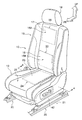
- Yes. 3 is a perspective view of the seat according to the present embodiment
- FIG. 4 is an enlarged cross-sectional view taken along the line 4-4 in FIG.
- a vehicle seat 10 as a seat in the present embodiment is disposed on a seat cushion 12 on which an occupant sits and a rear end side of the seat cushion 12, and a reclining mechanism 14 (see FIG. 1). ), And a headrest 18 that is provided at the upper end of the seatback 16 so as to be vertically adjustable and supports the head of the occupant.
- the vehicle seat 10 is attached to the passenger compartment floor 21 via a seat track (seat adjuster) 20. For this reason, the vehicle seat 10 is movable in the vehicle front-rear direction.
- the reclining center axis 14A of the reclining mechanism 14 in the vehicle seat 10 is arranged with the seat width direction (direction perpendicular to the paper surface in FIG. 1) as the axial direction.
- the reclining mechanism 14 The rotation of the motor 14B constituting the seat back 16 causes the seat back 16 to rotate forward (in the direction of arrow A in FIG. 2) or backward (in the direction of arrow B in FIG. 2) using the reclining center axis 14A as the rotation center axis. Yes.
- the seat cushion 22 has a seat cushion 22 on the seat cushion 22 where a seat occupant 26 sits in a seat 22 to detect the displacement of the pelvis 26 ⁇ / b> A (see FIG. 1) of the seat occupant 26.
- a pelvis detection sensor 24 as a pelvis detection unit is disposed, and the pelvis detection sensor 24 is configured by a sheet-like pressure sensor.
- the pelvis detection sensor 24 can detect the load acting on the seating portion 22 of the seat cushion 12 from the pelvis 26 ⁇ / b> A of the occupant 26 seated on the vehicle seat 10, and can detect the peak position. Yes.
- the pelvis detection sensor 24 is electrically connected to a control device 27 as a control unit, and the control device 27 is provided on the seat cushion 12.
- a thorax detection sensor 28 is provided as a thorax detection unit for detection, and the thorax detection sensor 28 is constituted by a sheet-like pressure sensor.
- the thorax is a thoracic skeleton formed into a saddle shape by the thoracic vertebrae, ribs, and sternum.
- the rib detection sensor 28 can detect a load acting on the upper portion 16 ⁇ / b> A of the seat back 16 from the rib 26 ⁇ / b> B of the occupant 26 seated on the vehicle seat 10. Specifically, the position 26C of at least one of the left and right shoulder blades in the seated occupant 26 can be detected. Instead of the scapula position 26C, another position may be detected.
- the thorax detection sensor 28 is electrically connected to the control device 27.
- the pelvis upper portion 26 ⁇ / b> D (see FIG. 1) of the seated occupant 26 is disposed inside the lower portion 16 ⁇ / b> B of the seatback 16 constituting the seatback occupant contact surface 19 on the lower side of the seatback 16.
- a pelvic upper part detection sensor 30 as a pelvic upper part detection unit for detecting the pelvis is arranged, and the pelvic upper part detection sensor 30 is constituted by a sheet-like pressure sensor.
- the pelvis upper part detection sensor 30 can detect the load acting on the lower part 16B of the seat back 16 from the pelvic upper part 26D of the occupant 26 seated on the vehicle seat 10, and can detect the peak position. ing. Further, the pelvic upper detection sensor 30 is electrically connected to the control device 27.
- the pelvis detection sensor 24 is built in a seat cover 38 that covers the seat pad 36 of the seating portion 22 in the seat cushion 12. More specifically, the seat cover 38 has a two-layer structure of a first layer 38A configured by genuine leather or the like and forming a design surface, and a second layer 38B configured by a foam material or the like, The pelvis detection sensor 24 is built in the second layer 38B. The pelvis detection sensor 24 may be disposed on the upper surface of the second layer 38B by pasting or the like.
- the thorax detection sensor 28 and the upper pelvis detection sensor 30 are also disposed on the seat skin 40 of the seat back 16 in the same manner.
- the seating portion 22 of the seat cushion 12 is connected to the seat cushion frame 42 via a seating portion moving device 46 as a pelvis moving portion.
- a motor 46 ⁇ / b> A that constitutes a part of the seating portion moving device 46 is electrically connected to the control device 27.
- the left and right guide rails 46 ⁇ / b> B constituting a part of the seating portion moving device 46 are arranged along the vehicle longitudinal direction between the bottom portion 42 ⁇ / b> A of the seat cushion frame 42 and the left and right frames 22 ⁇ / b> A of the seating portion 22. Is provided.
- the motor 46A of the seating portion moving device 46 rotates in a predetermined direction, so that the seating portion 22 moves along the guide rail 46B.
- the vehicle can move relative to the seat back 16 provided at the rear end of the vehicle forward (in the direction of arrow C in FIG. 2) or backward (in the direction of arrow D in FIG. 2).
- an upper moving device 50 as a seat back upper moving unit is provided inside the seat back 16 to move the upper portion 16 ⁇ / b> A of the seat back 16 in the vertical direction.
- a part of the motor 50 ⁇ / b> A is electrically connected to the control device 27.
- the left and right guide arms 50B constituting a part of the upper moving device 50 are extended from the upper portion 16A to the lower portion 16B of the seat back 16, and the left and right guide arms 50B are located above the seat (by rotation of the motor 50A). It moves in the direction of arrow E in FIG. 2 or below the seat (in the direction of arrow F in FIG. 2).
- the motor 50A rotates in a predetermined direction so that the upper portion 16A of the seat back 16 to which the guide arm 50B is attached is located above the lower portion 16B (see FIG. 2). Relative movement is possible in the direction of arrow E) or below the seat (in the direction of arrow F in FIG. 2).
- the seat back 16 is a pelvic upper support part
- the reclining mechanism 14 is a pelvic upper support part adjusting device.
- the thigh 26E of the seat occupant 26 is supported from below by the front portion 22B of the seat portion 22.
- the seated occupant 26 has a portion where the pelvis detection sensor 24 is disposed in the seating portion 22 and a front portion 22B, a portion where the thorax detection sensor 28 is disposed in the seat back 16, and a portion where the pelvis upper detection sensor 30 is disposed. And is supported at four locations.
- the control device 27 detects the seat occupant 26 detected by the pelvis detection sensor 24 provided on the seat portion 22 of the seat cushion 12 of the vehicle seat 10.
- An initial peak position P1 (not shown) at the load peak position P is detected from the load distribution of the pelvis 26A and stored.
- the position 26C of at least one of the left and right shoulder blades C is detected and stored as the initial position S1 (not shown).
- the load peak position P of the pelvis 26A is the position of the sciatic nodule.
- the seat occupant 26 when the occupant 26 is seated on the vehicle seat 10, the seat occupant 26 detected by the pelvic upper detection sensor 30 provided by the control device 27 at the lower portion of the seat back 16 of the vehicle seat 10.
- the initial position T1 (not shown) of the load peak position T is detected from the load distribution of the pelvic upper portion 26D and stored.
- the pelvis 26A When the occupant 26 is seated in the vehicle seat 10 for a long time, the pelvis 26A is generally shifted forward (in the direction of the arrow M in FIG. 1), and the rib cage 26B is rounded down by the spine. It shifts in the direction of arrow N in FIG.
- the control device 27 detects the seat seat occupant 26 detected by the pelvis detection sensor 24 provided at the seat portion 22 of the seat cushion 12 of the vehicle seat 10 at a predetermined timing, for example, after a predetermined time has elapsed.
- a peak position P2 (not shown) after displacement at the load peak position P is detected from the load distribution of the pelvis 26A, and compared with the initial peak position P1 detected earlier.
- the control device 27 eliminates this deviation.
- the seat 22 of the seat cushion 12 is moved forward or rearward of the vehicle.
- the seat cushion 12 is seated along the guide rail 46B of the seating portion moving device 46 by rotating the motor 46A of the seating portion moving device 46 in a predetermined direction by an output signal from the control device 27. 2 between the front position indicated by the two-dot chain line and the rear position indicated by the three-dot chain line in FIG. 2, the vehicle front (in the direction of arrow C in FIG. 2) or the vehicle rear (FIG. 2). In the direction of arrow D), and the deviation between the initial peak position P1 at the load peak position P and the peak position P2 after the displacement is eliminated.
- the controller 27 detects the position after displacement of the position 26C of the scapula from the load distribution of the rib 26B of the seated occupant 26 detected by the rib detection sensor 28 provided on the upper portion of the seat back 16 of the vehicle seat 10.
- S2 (not shown) is detected and compared with the initial position S1 detected previously.
- the control device 27 moves the seat upward or downward of the vehicle where the deviation is eliminated.
- the upper portion 16A of the back 16 is moved.
- the upper portion 16A of the seat back 16 is moved via the guide arm 50B of the upper moving device 50. 1 moves between the lower position shown in FIG. 1 and the upper position shown in FIG. 2 with respect to the lower portion 16B (upward in the direction of arrow E in FIG. 2) or down (in the direction of arrow F in FIG. 2).
- the deviation between the initial position S1 of the position 26C of the scapula and the position S2 after the displacement is eliminated.
- both the position of the pelvis 26A of the seated occupant 26 and the position 26C of at least one of the left and right shoulder blades as the position of the rib cage 26B are returned to the position before the displacement (initial position).
- the collapse of the sitting posture of the occupant 26 can be reduced over the entire body.
- the S-curve has an ideal shape. In this case, since this posture can be maintained, it is possible to suppress fatigue, low back pain and the like that occur due to the posture being broken.
- the control device 27 is detected by the pelvic upper detection sensor 30 provided at the lower portion of the seat back 16 of the vehicle seat 10.
- the peak position T2 (not shown) after displacement of the load peak position T is detected from the load distribution of the pelvic upper portion 26D of the seated occupant 26, and compared with the initial peak position T1 detected earlier.
- the control device 27 eliminates this deviation.
- the seat back 16 is tilted backward (in the direction of arrow A in FIG. 2) or rearward of the vehicle (in the direction of arrow B in FIG. 2).
- the seat back 16 is moved forward of the vehicle with the reclining central axis 14A as the rotational central axis (the arrow in FIG. 2). Tilt (rotate) toward the rear of the vehicle (direction A) or in the direction of arrow BA in FIG.
- the seat back 16 is tilted backward (in the direction of arrow B in FIG. 2).
- the seat back 16 is tilted forward of the vehicle (in the direction of arrow A in FIG. 2).
- FIG. 5 shows a schematic side view of the main part of the seat according to this embodiment
- FIG. 6 shows a perspective view of a part of the seat according to this embodiment.
- an S spring 70 as a pelvic upper support portion is provided at a portion that supports the pelvic upper portion 26 ⁇ / b> D of the occupant 26 at the lower portion of the seat back 16 of the vehicle seat 10 from the rear of the vehicle. Is arranged. Further, both end portions 70A of the S spring 70 are fixed to a moving body 72A of a spring moving device 72 as a pelvic upper support portion adjusting device, and the moving body 72A is connected to a motor 72B via a gear 72C. . Further, the motor 72B is electrically connected to the control device 27 (see FIG.
- the control device 27 rotates the motor 72B in a predetermined direction so that the moving body 72A is formed on the seat back frame 16C.
- the vehicle moves upward (in the direction of arrow G in FIG. 6) or downward (in the direction of arrow H in FIG. 6) along the hole 72D.
- the control device 27 starts from the load distribution of the pelvic upper portion 26D of the seated occupant 26.
- the deviation S disappears upward (in the direction of arrow G in FIG. 6) or downward (in the direction of arrow H in FIG. 6)
- the spring 70 is moved.
- the moving body 72A is moved along the guide hole 72D, so that the S spring 70 is moved.
- the vehicle is moved upward (in the direction of arrow G in FIG. 6) or downward (in the direction of arrow H in FIG. 6).
- the S spring 70 is moved upward (in the direction of arrow G in FIG. 6), and the pelvic upper portion 26D is supported by the S spring 70. To do.
- the S spring 70 is moved downward (in the direction of arrow H in FIG. 6), and the pelvic upper portion 26D is supported by the S spring 70. To do.
- the collapse of the sitting posture of the occupant 26 can be further reduced over the entire body.
- the seat back 16 or the S spring 70 serving as the pelvic upper support portion is operated after the seat portion moving device 46 and the upper moving device 50 are operated by the control device 27.
- the seating posture of the occupant 26 is activated by operating the seating portion moving device 46, the upper moving device 50, and the pelvic upper support portion (the seat back 16 or the S spring 70) simultaneously or in a predetermined order by the control device 27. You may make it reduce collapse of the whole body.
- the seat cover has a two-layer structure.
- each sensor such as a pelvis detection sensor is disposed between the seat cover and the seat pad with a single-layer structure, or a seat cover.
- Other structures such as a three-layer structure may be used.
- the seat of the present invention is applied to a vehicle seat.
- the seat of the present invention can also be applied to a seat other than the vehicle seat.
Landscapes
- Engineering & Computer Science (AREA)
- Aviation & Aerospace Engineering (AREA)
- Transportation (AREA)
- Mechanical Engineering (AREA)
- Seats For Vehicles (AREA)
- Chair Legs, Seat Parts, And Backrests (AREA)
- Acyclic And Carbocyclic Compounds In Medicinal Compositions (AREA)
Abstract
Priority Applications (5)
| Application Number | Priority Date | Filing Date | Title |
|---|---|---|---|
| EP09702110A EP2233345B1 (fr) | 2008-01-15 | 2009-01-14 | Siège |
| AT09702110T ATE550219T1 (de) | 2008-01-15 | 2009-01-14 | Sitz |
| CN2009801022857A CN101909932B (zh) | 2008-01-15 | 2009-01-14 | 座椅 |
| KR1020107017967A KR101155733B1 (ko) | 2008-01-15 | 2009-01-14 | 좌석 |
| US12/812,389 US8348339B2 (en) | 2008-01-15 | 2009-01-14 | Seat that detects pelvis and chest displacement |
Applications Claiming Priority (2)
| Application Number | Priority Date | Filing Date | Title |
|---|---|---|---|
| JP2008005655A JP4347385B2 (ja) | 2008-01-15 | 2008-01-15 | 座席 |
| JP2008-005655 | 2008-01-15 |
Publications (1)
| Publication Number | Publication Date |
|---|---|
| WO2009090954A1 true WO2009090954A1 (fr) | 2009-07-23 |
Family
ID=40885343
Family Applications (1)
| Application Number | Title | Priority Date | Filing Date |
|---|---|---|---|
| PCT/JP2009/050366 Ceased WO2009090954A1 (fr) | 2008-01-15 | 2009-01-14 | Siège |
Country Status (7)
| Country | Link |
|---|---|
| US (1) | US8348339B2 (fr) |
| EP (1) | EP2233345B1 (fr) |
| JP (1) | JP4347385B2 (fr) |
| KR (1) | KR101155733B1 (fr) |
| CN (1) | CN101909932B (fr) |
| AT (1) | ATE550219T1 (fr) |
| WO (1) | WO2009090954A1 (fr) |
Families Citing this family (39)
| Publication number | Priority date | Publication date | Assignee | Title |
|---|---|---|---|---|
| JP5458710B2 (ja) * | 2009-07-14 | 2014-04-02 | 東ソー株式会社 | ピンク色ジルコニア焼結体 |
| BR112013007306B1 (pt) | 2010-10-01 | 2020-08-04 | Nissan Motor., Ltd | Assento de veículo e método de ajsute de rigidez para o mesmo |
| WO2014066493A2 (fr) * | 2012-10-23 | 2014-05-01 | Lear Corporation | Système de siège de confort de région thoracique |
| WO2014084283A1 (fr) | 2012-11-28 | 2014-06-05 | テイ・エス テック株式会社 | Siège de véhicule |
| KR101522589B1 (ko) * | 2013-03-08 | 2015-05-26 | (주)릴렉스테크 | 안마 의자 |
| US10328823B2 (en) | 2014-06-09 | 2019-06-25 | Lear Corporation | Adjustable seat assembly |
| US9987961B2 (en) * | 2014-06-09 | 2018-06-05 | Lear Corporation | Adjustable seat assembly |
| JP6629501B2 (ja) * | 2014-08-27 | 2020-01-15 | 株式会社タチエス | 車両用シート |
| DE102014113869A1 (de) * | 2014-09-24 | 2016-03-24 | Mack Rides Gmbh & Co. Kg | Vorrichtung zur Rückhaltung eines Fahrgastes in einer Halterung eines Fahrgeschäftes |
| US9884570B2 (en) | 2015-05-19 | 2018-02-06 | Lear Corporation | Adjustable seat assembly |
| US9845026B2 (en) | 2015-05-19 | 2017-12-19 | Lear Corporation | Adjustable seat assembly |
| KR101801840B1 (ko) * | 2015-07-14 | 2017-11-28 | 서울대학교병원 | 요추 통증 완화를 위한 감압의자 및 감압장치. |
| US9661928B2 (en) | 2015-09-29 | 2017-05-30 | Lear Corporation | Air bladder assembly for seat bottoms of seat assemblies |
| US9758079B2 (en) * | 2015-10-08 | 2017-09-12 | Lear Corporation | Adjustable seat assembly |
| CN105253042A (zh) * | 2015-10-28 | 2016-01-20 | 桂林新艺制冷设备有限责任公司 | 一种具有变形的语音提示座椅 |
| US9827888B2 (en) | 2016-01-04 | 2017-11-28 | Lear Corporation | Seat assemblies with adjustable side bolster actuators |
| US10632866B2 (en) * | 2016-06-03 | 2020-04-28 | Faurecia Automotive Seating, Llc | Movement system for a vehicle seat |
| US10384565B2 (en) | 2016-07-29 | 2019-08-20 | Lear Corporation | Adjustable seat assembly |
| US10780801B2 (en) * | 2016-09-13 | 2020-09-22 | Tachi-S Co., Ltd. | Vehicle seat |
| US10232814B2 (en) * | 2017-01-18 | 2019-03-19 | Toyota Motor Engineering & Manufacturing North America, Inc. | Inflatable vehicle occupant positioning system |
| US11498461B2 (en) | 2017-02-17 | 2022-11-15 | Safran Seats Usa Llc | Passenger seat with comfort layout |
| EP3595928B1 (fr) * | 2017-03-17 | 2022-12-28 | Safran Seats USA LLC | Siège de passager avec portion de dossier mobile |
| DE102017206313B4 (de) * | 2017-04-12 | 2023-01-19 | Ford Global Technologies, Llc | Verfahren zur Sitzverstellung eines Verkehrsmittels |
| CN107089170B (zh) * | 2017-04-19 | 2019-09-06 | 京东方科技集团股份有限公司 | 座椅系统 |
| US10384566B2 (en) * | 2017-08-25 | 2019-08-20 | Ford Global Technologies, Llc | Vehicle seat assembly |
| JP6572336B2 (ja) * | 2018-02-13 | 2019-09-04 | 本田技研工業株式会社 | 車両用シートの乗員姿勢調節装置 |
| JP2019156247A (ja) | 2018-03-15 | 2019-09-19 | 本田技研工業株式会社 | シート装置 |
| JP6660425B2 (ja) * | 2018-07-20 | 2020-03-11 | ミネベアミツミ株式会社 | 姿勢制御装置 |
| US10611283B2 (en) * | 2018-09-12 | 2020-04-07 | Rockwell Collins, Inc. | Multi-stage seatback extension system |
| US10717534B2 (en) * | 2018-12-17 | 2020-07-21 | Goodrich Corporation | Extendable split headrest |
| JP2020111252A (ja) * | 2019-01-15 | 2020-07-27 | 日本発條株式会社 | 車両用シート |
| EP3914216B1 (fr) * | 2019-01-25 | 2024-02-21 | RC Services Australia Pty Ltd | Coussin de soutien |
| AT523112A1 (de) * | 2019-10-16 | 2021-05-15 | Zenzmaier Cornelia | Verfahren zur Orts- und Lagebestimmung eines Beckens einer Person |
| US11801776B2 (en) | 2020-12-09 | 2023-10-31 | Ford Global Technologies, Llc | Vehicle seating system |
| JP7728116B2 (ja) | 2021-07-30 | 2025-08-22 | 株式会社Subaru | シート |
| EP4166386B1 (fr) * | 2021-10-14 | 2025-11-12 | Ningbo Geely Automobile Research & Development Co. Ltd. | Siège de véhicule et procédé de fonctionnement d'un siège de véhicule |
| JP7804542B2 (ja) * | 2022-06-30 | 2026-01-22 | 株式会社Subaru | 肩甲骨位置推定装置及びシート |
| US12240360B2 (en) * | 2023-02-09 | 2025-03-04 | GM Global Technology Operations LLC | Vertically height adjustable seatback for a vehicle |
| US20250303932A1 (en) * | 2024-04-02 | 2025-10-02 | Ford Global Technologies, Llc | Extendable seatback |
Citations (6)
| Publication number | Priority date | Publication date | Assignee | Title |
|---|---|---|---|---|
| JPH076835Y2 (ja) * | 1989-07-05 | 1995-02-22 | 日産自動車株式会社 | 座 席 |
| JP3019344U (ja) | 1995-06-13 | 1995-12-12 | マミヤ・オーピー株式会社 | 組合せルアー |
| JP2001353039A (ja) | 2000-04-27 | 2001-12-25 | Faurecia Sieges D'automobile Sa | マッサージ効果を生じさせる自動車用座席の座部 |
| JP2005052433A (ja) * | 2003-08-05 | 2005-03-03 | Nissan Motor Co Ltd | 車両用シート装置 |
| JP2005125846A (ja) * | 2003-10-21 | 2005-05-19 | T S Tec Kk | 疲労低減機能付き自動車用シート |
| JP2006290099A (ja) * | 2005-04-08 | 2006-10-26 | Nissan Motor Co Ltd | 運転姿勢調整装置及び方法 |
Family Cites Families (8)
| Publication number | Priority date | Publication date | Assignee | Title |
|---|---|---|---|---|
| BE897046A (fr) * | 1983-06-14 | 1983-10-03 | Mevergnies Marcel Neve De | Fauteuil pour vehicule, notamment automobile |
| JP3006398B2 (ja) | 1993-05-05 | 2000-02-07 | インターナショナル・ビジネス・マシーンズ・コーポレイション | ケーブル・アセンブリ |
| US5836647A (en) * | 1997-05-20 | 1998-11-17 | Turman; Ben | Vehicle seat with shock absorption |
| DE19853156B4 (de) * | 1998-11-18 | 2006-04-13 | Girsberger Holding Ag | Sitz |
| US6640653B1 (en) * | 2002-05-30 | 2003-11-04 | Tachi-S Co., Ltd. | Load detection structure for vehicle seat |
| DE602004024276D1 (de) | 2003-10-21 | 2010-01-07 | Ts Tech Co Ltd | Fahrzeugsitz mit System zum Ermöglichen von Abbau der Müdigkeit von der im Sitz sitzenden Person |
| DE102006002919B4 (de) * | 2005-01-24 | 2008-09-04 | Denso Corp., Kariya | Kapazitiver Sensor und Insassenerfassungssystem |
| JP2008002838A (ja) * | 2006-06-20 | 2008-01-10 | Takata Corp | 車両乗員検出システム、作動装置制御システム、車両 |
-
2008
- 2008-01-15 JP JP2008005655A patent/JP4347385B2/ja not_active Expired - Fee Related
-
2009
- 2009-01-14 EP EP09702110A patent/EP2233345B1/fr not_active Not-in-force
- 2009-01-14 AT AT09702110T patent/ATE550219T1/de active
- 2009-01-14 WO PCT/JP2009/050366 patent/WO2009090954A1/fr not_active Ceased
- 2009-01-14 US US12/812,389 patent/US8348339B2/en not_active Expired - Fee Related
- 2009-01-14 KR KR1020107017967A patent/KR101155733B1/ko not_active Expired - Fee Related
- 2009-01-14 CN CN2009801022857A patent/CN101909932B/zh not_active Expired - Fee Related
Patent Citations (6)
| Publication number | Priority date | Publication date | Assignee | Title |
|---|---|---|---|---|
| JPH076835Y2 (ja) * | 1989-07-05 | 1995-02-22 | 日産自動車株式会社 | 座 席 |
| JP3019344U (ja) | 1995-06-13 | 1995-12-12 | マミヤ・オーピー株式会社 | 組合せルアー |
| JP2001353039A (ja) | 2000-04-27 | 2001-12-25 | Faurecia Sieges D'automobile Sa | マッサージ効果を生じさせる自動車用座席の座部 |
| JP2005052433A (ja) * | 2003-08-05 | 2005-03-03 | Nissan Motor Co Ltd | 車両用シート装置 |
| JP2005125846A (ja) * | 2003-10-21 | 2005-05-19 | T S Tec Kk | 疲労低減機能付き自動車用シート |
| JP2006290099A (ja) * | 2005-04-08 | 2006-10-26 | Nissan Motor Co Ltd | 運転姿勢調整装置及び方法 |
Also Published As
| Publication number | Publication date |
|---|---|
| JP4347385B2 (ja) | 2009-10-21 |
| JP2009165588A (ja) | 2009-07-30 |
| ATE550219T1 (de) | 2012-04-15 |
| US8348339B2 (en) | 2013-01-08 |
| CN101909932B (zh) | 2012-07-25 |
| EP2233345B1 (fr) | 2012-03-21 |
| EP2233345A4 (fr) | 2011-05-11 |
| CN101909932A (zh) | 2010-12-08 |
| EP2233345A1 (fr) | 2010-09-29 |
| KR101155733B1 (ko) | 2012-06-12 |
| KR20100101176A (ko) | 2010-09-16 |
| US20100283299A1 (en) | 2010-11-11 |
Similar Documents
| Publication | Publication Date | Title |
|---|---|---|
| JP4347385B2 (ja) | 座席 | |
| JP6647328B2 (ja) | 車両用シート | |
| KR102791546B1 (ko) | 자동차용 시트 제어 시스템 | |
| US6663178B2 (en) | Seat pan producing a massaging effect, in particular for automobile vehicle | |
| JP7534684B2 (ja) | 車両用シート | |
| JP2010057824A (ja) | 車両用シート構造 | |
| JP2019099133A (ja) | 乗員姿勢制御装置及び乗員姿勢制御方法 | |
| JP6582835B2 (ja) | 乗物用シート | |
| JP2004168224A (ja) | 車両用シート装置 | |
| JP4143963B2 (ja) | 車両用シート装置 | |
| JP4517882B2 (ja) | 車両用シート | |
| JP2019001315A (ja) | 車両用シート | |
| JP2009165735A (ja) | 座席 | |
| JP5935627B2 (ja) | シートフレーム | |
| JP2021046006A (ja) | 着座用シートのアームレスト装置 | |
| JP4544198B2 (ja) | 車両用シート装置 | |
| JP4517883B2 (ja) | 車両用シート | |
| JP7165096B2 (ja) | 座席シート | |
| JP7428553B2 (ja) | 車両用シート | |
| JP2009240373A (ja) | シート装置 | |
| JP7143573B2 (ja) | 車両用シート | |
| JPH0832512B2 (ja) | エアバッグ装着座席における位置制御装置 | |
| JP7803161B2 (ja) | 車両用シートバック | |
| US9119472B2 (en) | Movable seat insert | |
| JP2026053277A (ja) | 休息具、シート、乗り物用シートおよびベッド |
Legal Events
| Date | Code | Title | Description |
|---|---|---|---|
| WWE | Wipo information: entry into national phase |
Ref document number: 200980102285.7 Country of ref document: CN |
|
| 121 | Ep: the epo has been informed by wipo that ep was designated in this application |
Ref document number: 09702110 Country of ref document: EP Kind code of ref document: A1 |
|
| WWE | Wipo information: entry into national phase |
Ref document number: 12812389 Country of ref document: US |
|
| WWE | Wipo information: entry into national phase |
Ref document number: 2009702110 Country of ref document: EP |
|
| NENP | Non-entry into the national phase |
Ref country code: DE |
|
| ENP | Entry into the national phase |
Ref document number: 20107017967 Country of ref document: KR Kind code of ref document: A |