WO2009091020A1 - Appareil de travail au laser et procédé de travail au laser - Google Patents
Appareil de travail au laser et procédé de travail au laser Download PDFInfo
- Publication number
- WO2009091020A1 WO2009091020A1 PCT/JP2009/050518 JP2009050518W WO2009091020A1 WO 2009091020 A1 WO2009091020 A1 WO 2009091020A1 JP 2009050518 W JP2009050518 W JP 2009050518W WO 2009091020 A1 WO2009091020 A1 WO 2009091020A1
- Authority
- WO
- WIPO (PCT)
- Prior art keywords
- laser
- hole
- laser beam
- laser processing
- work
- Prior art date
- Legal status (The legal status is an assumption and is not a legal conclusion. Google has not performed a legal analysis and makes no representation as to the accuracy of the status listed.)
- Ceased
Links
Images


Classifications
-
- F—MECHANICAL ENGINEERING; LIGHTING; HEATING; WEAPONS; BLASTING
- F02—COMBUSTION ENGINES; HOT-GAS OR COMBUSTION-PRODUCT ENGINE PLANTS
- F02M—SUPPLYING COMBUSTION ENGINES IN GENERAL WITH COMBUSTIBLE MIXTURES OR CONSTITUENTS THEREOF
- F02M61/00—Fuel-injectors not provided for in groups F02M39/00 - F02M57/00 or F02M67/00
- F02M61/16—Details not provided for in, or of interest apart from, the apparatus of groups F02M61/02 - F02M61/14
- F02M61/168—Assembling; Disassembling; Manufacturing; Adjusting
-
- B—PERFORMING OPERATIONS; TRANSPORTING
- B23—MACHINE TOOLS; METAL-WORKING NOT OTHERWISE PROVIDED FOR
- B23K—SOLDERING OR UNSOLDERING; WELDING; CLADDING OR PLATING BY SOLDERING OR WELDING; CUTTING BY APPLYING HEAT LOCALLY, e.g. FLAME CUTTING; WORKING BY LASER BEAM
- B23K26/00—Working by laser beam, e.g. welding, cutting or boring
- B23K26/02—Positioning or observing the workpiece, e.g. with respect to the point of impact; Aligning, aiming or focusing the laser beam
- B23K26/06—Shaping the laser beam, e.g. by masks or multi-focusing
- B23K26/0604—Shaping the laser beam, e.g. by masks or multi-focusing by a combination of beams
- B23K26/0613—Shaping the laser beam, e.g. by masks or multi-focusing by a combination of beams having a common axis
-
- B—PERFORMING OPERATIONS; TRANSPORTING
- B23—MACHINE TOOLS; METAL-WORKING NOT OTHERWISE PROVIDED FOR
- B23K—SOLDERING OR UNSOLDERING; WELDING; CLADDING OR PLATING BY SOLDERING OR WELDING; CUTTING BY APPLYING HEAT LOCALLY, e.g. FLAME CUTTING; WORKING BY LASER BEAM
- B23K26/00—Working by laser beam, e.g. welding, cutting or boring
- B23K26/02—Positioning or observing the workpiece, e.g. with respect to the point of impact; Aligning, aiming or focusing the laser beam
- B23K26/06—Shaping the laser beam, e.g. by masks or multi-focusing
- B23K26/062—Shaping the laser beam, e.g. by masks or multi-focusing by direct control of the laser beam
- B23K26/0622—Shaping the laser beam, e.g. by masks or multi-focusing by direct control of the laser beam by shaping pulses
- B23K26/0624—Shaping the laser beam, e.g. by masks or multi-focusing by direct control of the laser beam by shaping pulses using ultrashort pulses, i.e. pulses of 1 ns or less
-
- B—PERFORMING OPERATIONS; TRANSPORTING
- B23—MACHINE TOOLS; METAL-WORKING NOT OTHERWISE PROVIDED FOR
- B23K—SOLDERING OR UNSOLDERING; WELDING; CLADDING OR PLATING BY SOLDERING OR WELDING; CUTTING BY APPLYING HEAT LOCALLY, e.g. FLAME CUTTING; WORKING BY LASER BEAM
- B23K26/00—Working by laser beam, e.g. welding, cutting or boring
- B23K26/08—Devices involving relative movement between laser beam and workpiece
- B23K26/0823—Devices involving rotation of the workpiece
-
- B—PERFORMING OPERATIONS; TRANSPORTING
- B23—MACHINE TOOLS; METAL-WORKING NOT OTHERWISE PROVIDED FOR
- B23K—SOLDERING OR UNSOLDERING; WELDING; CLADDING OR PLATING BY SOLDERING OR WELDING; CUTTING BY APPLYING HEAT LOCALLY, e.g. FLAME CUTTING; WORKING BY LASER BEAM
- B23K26/00—Working by laser beam, e.g. welding, cutting or boring
- B23K26/14—Working by laser beam, e.g. welding, cutting or boring using a fluid stream, e.g. a jet of gas, in conjunction with the laser beam; Nozzles therefor
- B23K26/142—Working by laser beam, e.g. welding, cutting or boring using a fluid stream, e.g. a jet of gas, in conjunction with the laser beam; Nozzles therefor for the removal of by-products
-
- B—PERFORMING OPERATIONS; TRANSPORTING
- B23—MACHINE TOOLS; METAL-WORKING NOT OTHERWISE PROVIDED FOR
- B23K—SOLDERING OR UNSOLDERING; WELDING; CLADDING OR PLATING BY SOLDERING OR WELDING; CUTTING BY APPLYING HEAT LOCALLY, e.g. FLAME CUTTING; WORKING BY LASER BEAM
- B23K26/00—Working by laser beam, e.g. welding, cutting or boring
- B23K26/36—Removing material
- B23K26/38—Removing material by boring or cutting
- B23K26/382—Removing material by boring or cutting by boring
- B23K26/389—Removing material by boring or cutting by boring of fluid openings, e.g. nozzles, jets
-
- F—MECHANICAL ENGINEERING; LIGHTING; HEATING; WEAPONS; BLASTING
- F02—COMBUSTION ENGINES; HOT-GAS OR COMBUSTION-PRODUCT ENGINE PLANTS
- F02M—SUPPLYING COMBUSTION ENGINES IN GENERAL WITH COMBUSTIBLE MIXTURES OR CONSTITUENTS THEREOF
- F02M2200/00—Details of fuel-injection apparatus, not otherwise provided for
- F02M2200/80—Fuel injection apparatus manufacture, repair or assembly
- F02M2200/8069—Fuel injection apparatus manufacture, repair or assembly involving removal of material from the fuel apparatus, e.g. by punching, hydro-erosion or mechanical operation
-
- F—MECHANICAL ENGINEERING; LIGHTING; HEATING; WEAPONS; BLASTING
- F02—COMBUSTION ENGINES; HOT-GAS OR COMBUSTION-PRODUCT ENGINE PLANTS
- F02M—SUPPLYING COMBUSTION ENGINES IN GENERAL WITH COMBUSTIBLE MIXTURES OR CONSTITUENTS THEREOF
- F02M61/00—Fuel-injectors not provided for in groups F02M39/00 - F02M57/00 or F02M67/00
- F02M61/16—Details not provided for in, or of interest apart from, the apparatus of groups F02M61/02 - F02M61/14
- F02M61/18—Injection nozzles, e.g. having valve seats; Details of valve member seated ends, not otherwise provided for
- F02M61/1806—Injection nozzles, e.g. having valve seats; Details of valve member seated ends, not otherwise provided for characterised by the arrangement of discharge orifices, e.g. orientation or size
Definitions
- the present invention relates to a laser processing apparatus and a laser processing method for forming a through hole by irradiating a workpiece with a laser beam.
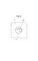
- FIG. 13 shows an overall schematic front view of a fuel injection valve 1 mounted on a vehicle.
- the fuel injection valve 1 has a nozzle holder 2 and a metal fuel injection nozzle 3 held at the tip of the nozzle holder 2.
- Reference numeral 4 denotes a suction port for suctioning fuel.
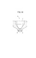
- FIG. 14 is a schematic vertical cross-sectional view of the main part of the tip of the fuel injection nozzle 3.
- the tip of the fuel injection nozzle 3 is configured as a hollow portion.
- the nozzle needle 5 is inserted into the hollow portion, and the hollow portion of the fuel injection nozzle 3 and a plurality of injection holes 6 formed in the tip of the fuel injection nozzle 3 are formed as the nozzle needle 5 is displaced. (In FIG. 14, only two of them are shown) and the fuel flow path is opened or closed.
- the laser beam is irradiated from the outer side of the tip. Therefore, the laser beam melts the wall portion of the tip portion from the outer wall side and travels to the inner wall side. Finally, the injection hole 6 is formed by melting the inner wall.
- a laser processing apparatus which irradiates the laser beam which acts in this way, the thing of patent 2623296 is mentioned, for example.
- the cross section of the collected laser beam may not be a perfect circle, which may lower the accuracy of the diameter, roundness, etc. of the injection hole. is there.
- finish processing by electrical discharge machining may be performed on the pore.
- an ultrashort pulse laser beam such as femtosecond laser beam.
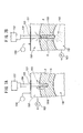
- the laser processing head 101 is moved right above the hole processing position of the workpiece 102.
- the laser beam 103 is irradiated from the laser processing head 101, and the pilot hole 104 is formed through the workpiece 102.
- the EDM head 105 is guided along the movable table 107, the EDM head 105 is moved just above the pilot hole 104, and the electrode 106 is lowered to perform EDM. As a result, the diameter of the pilot hole 104 is increased, and a through hole having a predetermined diameter is formed.
- the plume (plume, metal vapor from the workpiece as a source, mixed gas containing vapor from which the metal vapor is ionized, etc.) Occur. It has been pointed out that since this plume, in particular metal vapor, blocks the laser beam, it becomes difficult for the drilling process by the laser beam to progress.
- a general object of the present invention is to provide a laser processing apparatus in which it is easy to improve processing accuracy because it is difficult for a thermally deteriorated layer to be generated on a work.
- a main object of the present invention is to provide a laser processing apparatus which can prevent metal vapor from blocking laser light, and can thus efficiently advance drilling.
- Another object of the present invention is to provide a laser processing method in which a thermally deteriorated layer is not easily generated on a work.
- Another object of the present invention is to provide a laser processing method capable of efficiently advancing drilling.
- Still another object of the present invention is to provide a laser processing method capable of reducing the number of working processes.
- a laser processing apparatus for forming a through hole by irradiating at least one of nanosecond laser light and picosecond laser light to a closed portion of a hollow metal work
- a laser processing head having a first laser oscillation mechanism for irradiating the nanosecond laser light and a second laser oscillation mechanism for irradiating the picosecond laser light;
- a rotary holding mechanism for holding the metal work and rotating the metal work around a portion of the metal work to be irradiated with at least one of the nanosecond laser light and / or picosecond laser light;
- a vapor removal mechanism for suctioning metal vapor generated from the metal work when forming the through hole;
- Control means for controlling the drive and stop of the laser processing head, the rotation holding mechanism, and the vapor removal mechanism;
- a laser processing apparatus comprising:
- the vapor removal mechanism preferably has a suction means for suctioning metal vapor from the inner side of the metal work.
- a negative pressure larger than that of suctioning metal vapor from the outside of the metal work is generated. Therefore, even if a large amount of metal vapor is generated, suction and removal by the suction mechanism becomes extremely easy. In other words, metal vapor can be removed quickly.
- steam removal mechanism is what has a gas supply means which supplies gas after a through-hole is formed.
- the metal vapor can be easily pumped by the gas, it is possible to more easily avoid the retention of the metal vapor.
- a laser processing method for forming a through hole by irradiating at least one of nanosecond laser light and picosecond laser light to a closed portion of a hollow metallic work. , Irradiating the metal workpiece held by the rotation holding mechanism with the nanosecond laser beam from the first laser oscillation mechanism to form a through hole; After rotating the metal work under the action of the rotation holding mechanism, the picosecond laser beam is irradiated from the second laser oscillation mechanism to the inner wall of the through hole of the metal work which rotates.
- the process of finishing and Have During the step of forming the through holes, metal vapor is sucked from the outside of the metal work, Further, after the step of forming the through holes, a laser processing method is provided, in which gas is supplied from the outside of the metal work and suction is performed from the inside of the metal work.
- the present invention since it becomes possible to perform laser processing while rotating a metal work, it is possible to avoid the formation of a thermally deteriorated layer on the metal work. At the same time, since the irradiation position of the laser beam in the metal work can be changed, it is possible to form a perfect circular shape or a through hole close to a perfect circular shape. That is, it is possible to easily obtain a through hole with high accuracy.
- the metal vapor generated with the laser processing is suctioned and removed, the laser beam can be efficiently reached to the processing position. Therefore, it is also possible to advance laser processing efficiently.
- a laser processing method for forming a through hole in a work Irradiating the workpiece with a laser beam to form a perforated pilot hole; Expanding the diameter of the pilot hole with laser light while maintaining the laser light emission side at a low pressure as compared to the laser light incident side of the pilot hole; A laser processing method is provided.
- the pilot hole is formed through the laser beam and then the diameter of the pilot hole is increased by the laser beam. That is, since both the step of forming the pilot hole and the step of forming the pilot hole are performed by the laser beam, the processing tool can be made as in the prior art described in JP-A-2001-150248. There is no need to replace it. Since there is no replacement of the processing tool, the number of operation steps in forming the through hole can be reduced.
- a pressure difference is generated between the inlet side and the outlet side by setting the laser beam emitting side (outlet side) to a low pressure as compared with the laser beam incident side (inlet side) of the pilot hole.
- This pressure difference generates an air flow from the inlet side to the outlet side of the pilot hole.
- the inlet side is made higher than atmospheric pressure and the outlet side Should be lower than atmospheric pressure.
- the step of expanding the diameter of the pilot hole by the laser light it is preferable to rotate the optical axis of the laser light around the axis of the pilot hole.
- the area where the laser beam is irradiated to the work per unit time is increased. Therefore, since the processing volume per unit time also increases, the number of processing steps for forming the through hole can be reduced.
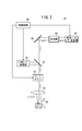
- FIG. 1 is a longitudinal sectional view showing an essential part of a laser processing apparatus according to a first embodiment of the present invention.
- FIG. 2 is a schematic circuit diagram of a laser processing head constituting the laser processing apparatus of FIG.
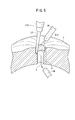
- FIG. 3 is a main part longitudinal cross-sectional view showing a state in which the fuel injection nozzle is irradiated with nanosecond laser light to form an injection hole.
- FIG. 4 is a plan view of relevant parts showing a state in which the fuel injection nozzle in which the injection hole is formed is rotated about the injection hole.
- FIG. 5 is an essential part perspective sectional view showing a state in which the inner peripheral wall of the injection hole is irradiated with picosecond laser light for finishing.
- FIG. 1 is a longitudinal sectional view showing an essential part of a laser processing apparatus according to a first embodiment of the present invention.
- FIG. 2 is a schematic circuit diagram of a laser processing head constituting the laser processing apparatus of FIG.
- FIG. 3 is a main part longitudinal cross-
- FIG. 6 is a longitudinal sectional view showing an essential part of a laser processing apparatus for carrying out a laser processing method according to a second embodiment of the present invention.
- FIG. 7A and FIG. 7B are flowcharts explaining the process of forming the pilot hole through.
- FIG. 8 is a flowchart for explaining the process of expanding the diameter of the pilot hole.
- FIG. 9 is a view from the direction of arrow b in FIG.
- FIG. 10A and FIG. 10B are schematic explanatory drawings which show the effect
- FIG. 11 is a cross-sectional view of a processed hole showing the influence of air flow on processing.
- FIG. 12 is a diagram showing the difference in processing time depending on the presence or absence of a pressure difference.
- FIG. 13 is an overall schematic front view of a fuel injection valve mounted on a vehicle.
- FIG. 14 is a schematic vertical cross-sectional view of a tip portion of a fuel injection nozzle that constitutes the fuel injection valve.
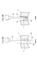
- FIG. 15 is a schematic perspective view of relevant parts showing a state in which a pilot hole is formed through in the prior art.
- FIG. 16 is a schematic perspective view of relevant parts showing a state in which the pilot hole is expanded in the prior art.
- FIG. 1 is a longitudinal sectional view showing an essential part of a laser processing apparatus 10 according to a first embodiment of the present invention.
- the laser processing apparatus 10 includes a rotation holding mechanism 12 for holding a fuel injection nozzle 3 (metal work), a laser processing head 14 for irradiating the fuel injection nozzle 3 with a laser beam described later, and an injection hole 6. It has a vapor removal mechanism to be described later for suctioning metal vapor generated from the fuel injection nozzle 3 during formation.
- the rotation holding mechanism 12 has a base portion 16, a rotation portion 20 rotatably supported by the base portion 16 via a bearing 18, and a work holding portion 22 provided on the top of the rotation portion 20.
- a rotation drive motor 24 is attached to the base portion 16.
- a drive pulley 26 is fitted to the rotation shaft 25 of the rotation drive motor 24.
- the rotating portion 20 includes a rotating cylindrical member 34 attached to the bearing 18 by a collar 28 and a nut 30, and a driven pulley 36 is externally fitted to a small diameter cylindrical tip of the rotating cylindrical member 34.
- a belt 38 is wound around the driven pulley 36 and the drive pulley 26.
- the work holding portion 22 includes a holding base 42 connected to the rotary cylinder member 34 via the stop shaft 40 and a work holding body having a substantially T-shaped cross section rotatably attached to the holding base 42 via the bearing 43. 44, a collar 48 and a nut 50 for preventing removal of the workpiece holding body 44 from the bearing 43, an annular member 54 connected to the holding base 42 to support the seal member 52, and one end of the workpiece holding body 44 An extension member 56 extending from the holding base 42 to the end of the workpiece holding body 44 for supporting, and a driving device (not shown) attached to the end of the workpiece holding body 44 to rotate the workpiece holding body 44 And a work rotation angle indexing mechanism 60 for positioning the work holding main body 44 at each predetermined angle.
- Reference numeral 62 is a positioning pin for preventing the fuel injection nozzle 3 from rotating when the work holding body 44 supports the fuel injection nozzle 3.
- a first passage 64 communicating with the inside of the fuel injection nozzle 3 and a second passage 66 orthogonal to the first passage 64 are formed inside the work holding body 44.
- the second passage 66 communicates with a third passage 68 formed inside the extension member 56.
- the third passage 68 communicates with the hollow portion 71 of the rotary cylinder member 34 via the fourth passage 70 formed in the holding base 42.
- the workpiece rotation angle indexing mechanism 60 has a plurality of recesses 74 provided at predetermined angles along the circumferential direction on the outer peripheral surface of the large diameter portion 72 constituting the workpiece holding main body 44 and the large diameter portion of the holding base 42
- a case 76 provided to face the outer peripheral surface of the ball 72, a ball 78 disposed in the case 76 and capable of fitting to each of the recesses 74, and the balls 78 being resiliently urged toward the recess 74 side
- a coil spring 80 for biasing.
- the side face of the holding base 42 constituting the work holding portion 22 facing the work holding main body 44 corresponds to the weight of the work holding main body 44 and the fuel injection nozzle 3 in order to smoothly rotate the holding base 42.
- Counter weight means (not shown) are provided.
- a counterweight means what attaches a weight corresponding to the weight is illustrated.
- a tank in which the liquid is stored is provided in the holding base 42, and a sensor (not shown) disposed in the base portion 16 monitors the swing of the rotary cylindrical member 34, and a signal generated by the sensor according to the swing amount
- the control circuit 98 see FIG.
- liquid such as water to the tank so as to reduce the swing of the rotary cylinder member 34.
- liquid water or the like
- the weight of the counterweight means is changed according to the weight of the fuel injection nozzle 3 to be processed.
- the separation distance between the adjacent recesses 74 corresponds to the separation distance between the adjacent injection holes 6 in the fuel injection nozzle 3.
- the laser processing head 14 includes a nanosecond laser oscillator 82 for oscillating the nanosecond laser beam L1 and an ultrashort pulse laser oscillator 84 (picosecond laser oscillator) for oscillating the picosecond laser beam L2.
- the laser processing head 14 further includes an amplifier 86 for amplifying the picosecond laser beam L2 oscillated from the ultrashort pulse laser oscillator 84, and a mirror for reflecting the picosecond laser beam L2 output from the amplifier 86.
- a condenser lens 92 for condensing the second laser light L1 and the picosecond laser light L2 on the fuel injection nozzle 3.
- the vapor removal mechanism includes a suction mechanism (not shown) capable of suctioning from the hollow portion 71 of the rotary cylindrical member 34 via a suction nozzle 94 (see FIG. 5) inserted inward of the fuel injection nozzle 3, and a fuel It has a suction and supply mechanism provided with a suction and supply nozzle 96 (see FIGS. 1 and 2) disposed in the vicinity of the outside of the injection nozzle 3.
- a suction mechanism (not shown) capable of suctioning from the hollow portion 71 of the rotary cylindrical member 34 via a suction nozzle 94 (see FIG. 5) inserted inward of the fuel injection nozzle 3, and a fuel It has a suction and supply mechanism provided with a suction and supply nozzle 96 (see FIGS. 1 and 2) disposed in the vicinity of the outside of the injection nozzle 3.
- the rotation drive motor 24, the nanosecond laser oscillator 82, the ultrashort pulse laser oscillator 84, the beam rotator 90, the suction mechanism, the suction / supply mechanism and the drive unit are electrically connected to the control circuit 98 (see FIG. 2). Connected.
- the laser processing method according to the first embodiment is implemented as follows using the laser processing apparatus 10 configured as described above.
- the nanosecond laser beam L1 is oscillated from the laser processing head 14 without driving the rotation drive motor 24. That is, the nanosecond laser oscillator 82 is driven by the control device, and the nanosecond laser beam L1 is irradiated to a predetermined position of the fuel injection nozzle 3 under the action of the beam rotator 90 and the condenser lens 92. At the same time, drive the suction and supply mechanism.
- the fuel injection nozzle 3 is melted from the outer wall side to form a melted portion S.
- a fused portion S generates a plume V containing a large amount of metal vapor. If this plume V intercepts the nanosecond laser beam L 1, it hinders the progress of the drilling process (laser process), but in the first embodiment, the plume V is rapidly sucked through the suction / supply nozzle 96 . Therefore, since the nanosecond laser beam L1 easily reaches the predetermined position of the fuel injection nozzle 3, the laser processing proceeds efficiently.
- the melting of the portion of the fuel injection nozzle 3 irradiated with the nanosecond laser beam L1 finally proceeds to the inner wall facing the hollow interior. Thereby, a through hole as the injection hole 6 is formed.
- the control circuit 98 After stopping the driving of the nanosecond laser oscillator 82, the control circuit 98 issues a command signal “drive the rotation drive motor 24”.
- the rotational drive motor 24 that has received the command signal causes the rotation shaft 25 to rotate.
- the drive pulley 26 rotates, and as a result, the driven pulley 36 rotates via the belt 38, whereby the rotary cylinder member 34 starts the rotation operation.
- the control circuit 98 drives the ultrashort pulse laser oscillator 84 to irradiate the picosecond laser beam L2 near the opening of the injection hole 6 under the action of the beam rotator 90 and the focusing lens 92.
- the suction / supply mechanism and the suction mechanism are driven.
- the compressed gas is supplied from the suction / supply nozzle 96 located outward of the fuel injection nozzle 3, while the suction mechanism sucks in via the suction nozzle 94 inserted inward of the fuel injection nozzle 3. Do.
- the picosecond laser beam L2 proceeds so as to be slightly inclined with respect to the axis of the injection hole 6. Thereby, the inner peripheral wall of the injection hole 6 is melted, the injection hole 6 is finished to a predetermined diameter, and the inner peripheral wall is finished to a predetermined surface roughness. That is, the injection holes 6 are subjected to finish processing.
- the plume V generated as the inner peripheral wall melts is quickly pressure-fed to the inside of the fuel injection nozzle 3 by the compressed gas discharged through the suction / supply nozzle 96.
- the suction nozzle 94 is disposed inward of the fuel injection nozzle 3 as described above, and the suction mechanism performs suction via the suction nozzle 94, the plume V is quickly suctioned. It is sucked by the mechanism.
- the plume V tends to stay in layers inside the injection holes 6.
- the plume V is suctioned at the inner side.
- the suction is performed from the inside of the fuel injection nozzle 3
- the negative pressure becomes larger than when the suction is performed from the outside. Therefore, even if the volume V is large, it can be easily suctioned and removed.
- the plume V can be quickly removed for the reasons as described above.
- picosecond laser light L2 can be easily made to reach the inner peripheral wall, so that laser processing on the inner peripheral wall can be efficiently advanced.
- the picosecond laser beam L2 Since the picosecond laser beam L2 is irradiated while rotating the fuel injection nozzle 3, the picosecond laser beam L2 always reaches the inner peripheral wall of the injection hole 6. For this reason, even if the cross-sectional shape of the focused picosecond laser beam L2 is non-circular, the substantially perfect injection hole 6 can be obtained.
- the fuel injection nozzle 3 is rotated, it is possible to form a circular injection hole 6 having a true circular shape or a near perfect circular shape. In other words, there is an advantage that the injection holes 6 can be formed with high accuracy.
- the control circuit 98 issues a command signal for rotating the fuel injection nozzle 3 by a predetermined angle to the drive device.
- the driving device receiving this signal rotates the workpiece holding main body 44 via the driven gear 58 to rotate the fuel injection nozzle 3 by a predetermined angle.
- the ball 78 is fitted into the recess 74 of the workpiece rotation angle indexing mechanism 60, whereby the fuel injection nozzle 3 is positioned. Drilling is performed on the positioned tip in the same manner as described above, and a new injection hole 6 is formed. With the formation of the predetermined number of injection holes 6, all the drilling processes are completed.
- suction function may be performed by the suction / supply mechanism, and suction of the plume V may be performed from both the outer side and the inner side of the hollow metal work (for example, the fuel injection nozzle 3).
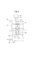
- FIG. 6 is a longitudinal sectional view showing an essential part of a laser processing apparatus 120 for implementing the laser processing method according to the second embodiment.
- the laser processing apparatus 120 includes a laser oscillator 121, a processing head 122 provided below the laser oscillator 121 to emit a laser beam, and a workpiece holder 123 disposed below the processing head 122.
- the workpiece holding portion 123 includes a holding base 124 serving as a base, a workpiece holding body 126 rotatably attached to the holding base 124 via bearings 125, 125, and bearings 125, 125 of the workpiece holding body 126.
- a drive gear 133 attached to the drive unit 132 for transmitting a driving force, and a proximal end of the workpiece holding body 126 for obtaining a driving force from the drive gear 133.
- the driven gear 134 attached to the A seal member 135 disposed at the base end of the holding body 126, a work rotation angle indexing mechanism 140 for positioning the work holding body 126 at each predetermined rotation angle, and the inside and the outside of the fuel injection nozzle 3 as a work And a pressure difference generating mechanism 150 for generating a pressure difference.
- Reference numeral 148 denotes a positioning pin for stopping rotation of the fuel injection nozzle 3 with respect to the work holding body 126 when the work holding body 126 supports the fuel injection nozzle 3
- reference numeral 149 denotes the fuel injection nozzle 3 and It is a seal member which shuts off the flow of gas in the gap of the work holding body 126.
- the workpiece holding body 126 is a member in which a passage 136 communicating with the passage 118 in the fuel injection nozzle 3 is formed.
- the passage 136 communicates with the hollow portion 137 formed in the holding base 124.
- the passages 118 and 136 and the hollow portion 137 constitute a plume suction passage 138 for suctioning a plume generated during laser processing.
- the workpiece rotation angle indexing mechanism 140 opposes the outer peripheral surface of the large diameter portion 141 with a plurality of recessed portions 142 formed at predetermined angles in the circumferential direction on the outer peripheral surface of the large diameter portion 141 provided in the workpiece holding main body 126
- a compression spring 145 provided.
- the distance between the adjacent recesses 142 and 142 corresponds to the distance between the adjacent injection holes 6 in the fuel injection nozzle 3.
- the pressure difference generation mechanism 150 is attached to the holding base 124 and encloses the fuel injection nozzle 3, the sealing member 153 provided at the end of the sealing member 151 to shut off gas leakage, and irradiation from the processing head 122 And a high pressure gas supply source 156 for introducing a high pressure gas into the high pressure chamber 152 in order to make the high pressure chamber 152 higher than atmospheric pressure, and a high pressure chamber 152.
- the gas passage 157 is connected to lead the gas sucked from the high pressure chamber 152
- the suction passage 158 is connected to the plume suction passage 138 and leads the gas sucked from the plume suction passage 138
- the gas passage to be sucked is A three-way valve 161 that switches to either the gas passage 157 or the suction passage 158 and a sore that switches the three-way valve 161 And id 162, consisting of a vacuum pump 163 for sucking gas from the high pressure chamber 152 or plume suction passage 138.
- a compressor is preferably employed if the gas is air, and a gas cylinder is preferably employed if the gas is nitrogen.
- nitrogen gas is a non-oxidative gas, it can prevent the metal, which is the material of the fuel injection nozzle 3 which is a work, from being oxidized, and is a preferable gas.
- gas cylinders are generally expensive and disadvantageous in cost.
- FIGS. 7A and 7B are diagrams for explaining the process of forming the pilot hole through, first, as shown in FIG. 7A, the laser beam from the processing head 122 with the high pressure chamber 152 maintained at atmospheric pressure or slightly high pressure. The point 154 is fired to irradiate the tip 16 of the fuel injection nozzle 3. Processing causes a plume 165 to be generated.
- the pilot holes 166 penetrate as shown in FIG. 7B.
- the injection hole 6 which should be formed is shown with the dashed-two dotted line.
- FIG.8 and FIG.9 is a flowchart explaining the process of diameter-expanding a pilot hole.
- the laser beam 154 is irradiated while maintaining the above-mentioned pressure difference, and the diameter of the pilot hole 166 is enlarged to perform finish processing.
- the pressure difference causes the air to flow as shown by arrow (2), and the plume 165 is swept into the passage 118. Therefore, the irradiation of the laser beam 154 is avoided from being blocked by the plume 165, so the irradiation efficiency of the laser beam 154 does not decrease.
- the laser beam 154 is rotated, and the diameter of the pilot hole 166 is enlarged by the laser beam 154 shown by an imaginary line, and the finish processing of the injection hole 6 is completed.
- FIG. 9 is a view as viewed from the direction of arrow b in FIG. 8, and the area where the laser beam 154 is irradiated to the fuel injection nozzle 3 per unit time is made by rotating the laser beam 154 at high speed By increasing the speed, high speed processing can be performed.
- FIG. 10A and FIG. 10B are figures which show the effect
- the plume 165 is discharged from the inside of the injection hole 6 as indicated by the arrow (5) because of the air flow due to the pressure difference.
- the injection holes 6 can be processed in a short time.
- 11A and 11B are cross-sectional views of the processing hole for explaining the influence of the air flow on processing, and the condition of the laser light in the diameter expansion step is 3 kHz in frequency, 2 mJ in energy, and the rotation number of the laser light.
- the processing time was 30 seconds at 3000 rpm.
- the processed surface becomes rough.
- the diameter of the opening on the upper side of the drawing of the injection hole 6 is 63 ⁇ m
- the diameter of the opening on the lower side of the drawing is 33 ⁇ m
- the diameter of the injection hole 6 is not uniform.
- the processing volume was 947 ⁇ m 3 and was small.
- the machined surface is fine.
- the diameter of the opening at the upper side of the drawing of the injection hole 6 is 76 ⁇ m
- the diameter of the opening at the lower side of the drawing is 63 ⁇ m
- the diameter of the injection hole 6 is substantially uniform.
- the processing volume is 1930 ⁇ m 3 and is large.
- FIG. 12 is a view showing a processing time depending on the presence or absence of a pressure difference. In the comparative example processed without a pressure difference, it takes 1 second to complete the through hole processing and 60 seconds to finish the finish processing.
- the work is not particularly limited to the fuel injection nozzle 3.
- the laser processing apparatus and the laser processing method according to the present invention are particularly effective when forming injection holes of a fuel injection nozzle that constitutes a fuel injection valve.
Landscapes
- Engineering & Computer Science (AREA)
- Physics & Mathematics (AREA)
- Optics & Photonics (AREA)
- Mechanical Engineering (AREA)
- Plasma & Fusion (AREA)
- Manufacturing & Machinery (AREA)
- Chemical & Material Sciences (AREA)
- Combustion & Propulsion (AREA)
- General Engineering & Computer Science (AREA)
- Fuel-Injection Apparatus (AREA)
- Laser Beam Processing (AREA)
Abstract
Priority Applications (3)
| Application Number | Priority Date | Filing Date | Title |
|---|---|---|---|
| US12/812,195 US8258429B2 (en) | 2008-01-17 | 2009-01-16 | Laser working apparatus, and laser working method |
| DE112009000138.6T DE112009000138B4 (de) | 2008-01-17 | 2009-01-16 | Laserbearbeitungsvorrichtung und Laserbearbeitungsverfahren |
| CN200980102448.1A CN101909808B (zh) | 2008-01-17 | 2009-01-16 | 激光加工装置和激光加工方法 |
Applications Claiming Priority (4)
| Application Number | Priority Date | Filing Date | Title |
|---|---|---|---|
| JP2008-008439 | 2008-01-17 | ||
| JP2008008439 | 2008-01-17 | ||
| JP2008-022716 | 2008-02-01 | ||
| JP2008022716A JP4790737B2 (ja) | 2008-02-01 | 2008-02-01 | レーザ加工装置及びレーザ加工方法 |
Publications (1)
| Publication Number | Publication Date |
|---|---|
| WO2009091020A1 true WO2009091020A1 (fr) | 2009-07-23 |
Family
ID=40885402
Family Applications (1)
| Application Number | Title | Priority Date | Filing Date |
|---|---|---|---|
| PCT/JP2009/050518 Ceased WO2009091020A1 (fr) | 2008-01-17 | 2009-01-16 | Appareil de travail au laser et procédé de travail au laser |
Country Status (4)
| Country | Link |
|---|---|
| US (1) | US8258429B2 (fr) |
| CN (1) | CN101909808B (fr) |
| DE (1) | DE112009000138B4 (fr) |
| WO (1) | WO2009091020A1 (fr) |
Cited By (2)
| Publication number | Priority date | Publication date | Assignee | Title |
|---|---|---|---|---|
| CN109366014A (zh) * | 2018-12-21 | 2019-02-22 | 武汉欧双光电科技股份有限公司 | 一种生陶瓷激光切割设备 |
| JP2021159948A (ja) * | 2020-03-31 | 2021-10-11 | 本田技研工業株式会社 | レーザ加工装置及びレーザ加工方法 |
Families Citing this family (21)
| Publication number | Priority date | Publication date | Assignee | Title |
|---|---|---|---|---|
| DE102009007164A1 (de) * | 2009-02-03 | 2010-08-12 | Rolls-Royce Deutschland Ltd & Co Kg | Verfahren zum Ausbilden einer Kühlluftöffnung in einer Wand einer Gasturbinenbrennkammer sowie nach dem Verfahren hergestellte Brennkammerwand |
| DE102011078346A1 (de) * | 2011-06-29 | 2013-01-03 | Robert Bosch Gmbh | Schaltventil, Verfahren zum Herstellen eines Schaltventils und Kraftstoffinjektor mit einem Schaltventil |
| US8601663B2 (en) | 2012-02-13 | 2013-12-10 | Honeywell International Inc. | Methods for structural repair of components having damaged internally threaded openings and components repaired using such methods |
| JP6222903B2 (ja) * | 2012-08-17 | 2017-11-01 | 株式会社ディスコ | レーザ加工装置 |
| KR102096048B1 (ko) * | 2012-10-10 | 2020-04-02 | 삼성디스플레이 주식회사 | 레이저 가공장치 |
| CN103143841B (zh) * | 2013-03-08 | 2014-11-26 | 西北工业大学 | 一种利用皮秒激光加工孔的方法 |
| DE102013217386A1 (de) | 2013-09-02 | 2015-03-05 | Evonik Industries Ag | Verfahren zur Herstellung von Acrylsäure |
| JP6215261B2 (ja) | 2014-06-27 | 2017-10-18 | 日東電工株式会社 | 長尺状の偏光子、長尺状の偏光板および画像表示装置 |
| EP3183091B8 (fr) * | 2014-08-19 | 2018-09-05 | Lumileds Holding B.V. | Collecteur de saphir pour reduire l'endommagement mécanique durant lift-off au niveau puce |
| JP6239481B2 (ja) * | 2014-10-08 | 2017-11-29 | 株式会社東芝 | 溶接装置およびノズル装置 |
| KR102572643B1 (ko) * | 2015-05-13 | 2023-08-31 | 루미리즈 홀딩 비.브이. | 다이 레벨의 레이저 리프트-오프 중에 기계적 손상을 줄이기 위한 사파이어 수집기 |
| JP6342949B2 (ja) * | 2016-05-17 | 2018-06-13 | ファナック株式会社 | 反射光を抑制しながらレーザ加工を行うレーザ加工装置及びレーザ加工方法 |
| DE102017001785A1 (de) * | 2017-02-24 | 2018-08-30 | Stabilus Gmbh | Verfahren zur Fertigung eines Düsenkolbens, Produktionsverfahren für einen Dämpfer, Düsenkolben, Dämpfer, Produktionsanlage zur Produktion eines Dämpfers |
| US11548099B2 (en) | 2018-12-03 | 2023-01-10 | Mitsubishi Electric Corporation | Laser processing method and laser processing apparatus |
| JP7291510B2 (ja) * | 2019-03-25 | 2023-06-15 | 三菱重工業株式会社 | レーザ加工方法 |
| CA3176138A1 (fr) * | 2020-03-31 | 2021-10-07 | Honda Motor Co., Ltd. | Procede d'usinage au laser |
| US20210310122A1 (en) * | 2020-04-03 | 2021-10-07 | Applied Materials, Inc. | Method of forming holes from both sides of substrate |
| CN111408855B (zh) * | 2020-04-10 | 2022-01-11 | 一汽解放汽车有限公司 | 一种周向微孔激光加工自动找正装置及方法 |
| US12030135B2 (en) | 2020-10-14 | 2024-07-09 | Applied Materials, Inc. | Methods to fabricate chamber component holes using laser drilling |
| US11819948B2 (en) | 2020-10-14 | 2023-11-21 | Applied Materials, Inc. | Methods to fabricate chamber component holes using laser drilling |
| CN120715373A (zh) * | 2025-09-03 | 2025-09-30 | 苏州益腾电子科技有限公司 | 一种液态金属轴承制备方法及液态金属轴承 |
Citations (3)
| Publication number | Priority date | Publication date | Assignee | Title |
|---|---|---|---|---|
| JPH02147187A (ja) * | 1988-11-29 | 1990-06-06 | Sumitomo Metal Ind Ltd | 複合熱源による製管溶接方法 |
| JP2003260580A (ja) * | 2002-03-08 | 2003-09-16 | Toyoda Mach Works Ltd | レーザ加工装置 |
| JP2007237210A (ja) * | 2006-03-07 | 2007-09-20 | Aisin Seiki Co Ltd | レーザ加工法及び装置 |
Family Cites Families (10)
| Publication number | Priority date | Publication date | Assignee | Title |
|---|---|---|---|---|
| EP0299143A1 (fr) | 1987-06-12 | 1989-01-18 | Raycon Textron Inc. | Installation de production pour percer par rayon laser et utilisation d'électro-érosion |
| JP2001150248A (ja) | 1999-09-09 | 2001-06-05 | Fine Device:Kk | 細孔の加工方法及び装置 |
| US8217304B2 (en) * | 2001-03-29 | 2012-07-10 | Gsi Group Corporation | Methods and systems for thermal-based laser processing a multi-material device |
| JP3982136B2 (ja) | 2000-02-04 | 2007-09-26 | セイコーエプソン株式会社 | レーザ加工方法及びその装置 |
| DE10054853A1 (de) | 2000-11-06 | 2002-08-01 | Bosch Gmbh Robert | Verfahren zum Einbringen eines Mikrolochs in ein vorzugsweise metallisches Werkstück und Vorrichtung hierzu |
| JP4207788B2 (ja) | 2004-01-30 | 2009-01-14 | トヨタ自動車株式会社 | インジェクタノズル孔加工方法 |
| US8148211B2 (en) * | 2004-06-18 | 2012-04-03 | Electro Scientific Industries, Inc. | Semiconductor structure processing using multiple laser beam spots spaced on-axis delivered simultaneously |
| DE102004050047A1 (de) | 2004-10-14 | 2006-04-27 | Robert Bosch Gmbh | Verfahren und Vorrichtung zur Erzeugung von Bohrungen mittels Laser |
| US20070069429A1 (en) * | 2005-09-29 | 2007-03-29 | Albrecht Thomas R | System and method for patterning a master disk for nanoimprinting patterned magnetic recording disks |
| KR100795526B1 (ko) * | 2006-03-02 | 2008-01-16 | 한국표준과학연구원 | 물질상태변이 유발을 통한 레이저 가공방법 및 가공장치 |
-
2009
- 2009-01-16 DE DE112009000138.6T patent/DE112009000138B4/de active Active
- 2009-01-16 CN CN200980102448.1A patent/CN101909808B/zh not_active Expired - Fee Related
- 2009-01-16 US US12/812,195 patent/US8258429B2/en active Active
- 2009-01-16 WO PCT/JP2009/050518 patent/WO2009091020A1/fr not_active Ceased
Patent Citations (3)
| Publication number | Priority date | Publication date | Assignee | Title |
|---|---|---|---|---|
| JPH02147187A (ja) * | 1988-11-29 | 1990-06-06 | Sumitomo Metal Ind Ltd | 複合熱源による製管溶接方法 |
| JP2003260580A (ja) * | 2002-03-08 | 2003-09-16 | Toyoda Mach Works Ltd | レーザ加工装置 |
| JP2007237210A (ja) * | 2006-03-07 | 2007-09-20 | Aisin Seiki Co Ltd | レーザ加工法及び装置 |
Cited By (3)
| Publication number | Priority date | Publication date | Assignee | Title |
|---|---|---|---|---|
| CN109366014A (zh) * | 2018-12-21 | 2019-02-22 | 武汉欧双光电科技股份有限公司 | 一种生陶瓷激光切割设备 |
| JP2021159948A (ja) * | 2020-03-31 | 2021-10-11 | 本田技研工業株式会社 | レーザ加工装置及びレーザ加工方法 |
| JP7370293B2 (ja) | 2020-03-31 | 2023-10-27 | 本田技研工業株式会社 | レーザ加工装置及びレーザ加工方法 |
Also Published As
| Publication number | Publication date |
|---|---|
| US20100282727A1 (en) | 2010-11-11 |
| CN101909808A (zh) | 2010-12-08 |
| DE112009000138T5 (de) | 2010-11-18 |
| DE112009000138B4 (de) | 2016-04-14 |
| US8258429B2 (en) | 2012-09-04 |
| CN101909808B (zh) | 2014-04-30 |
Similar Documents
| Publication | Publication Date | Title |
|---|---|---|
| WO2009091020A1 (fr) | Appareil de travail au laser et procédé de travail au laser | |
| CN105339129B (zh) | 借助激光束刺入金属工件中的方法 | |
| JP5192216B2 (ja) | レーザー加工装置 | |
| JP3871240B2 (ja) | ハイブリッド加工装置 | |
| JP2011041962A (ja) | レーザー加工装置 | |
| JP6334235B2 (ja) | レーザー加工装置 | |
| WO2018008400A1 (fr) | Appareil d'usinage au laser et procédé d'usinage au laser | |
| JP5208615B2 (ja) | 穴加工方法 | |
| US6969822B2 (en) | Laser micromachining systems | |
| JP5467345B2 (ja) | ディスプレイパネルへの塗布方法およびディスプレイパネルの製造方法 | |
| JP4861225B2 (ja) | 細穴の放電加工方法及び細穴の放電加工装置 | |
| JP5017882B2 (ja) | ハイブリッドレーザ加工方法 | |
| JP2000237886A (ja) | レーザーピアシング方法 | |
| JP4790737B2 (ja) | レーザ加工装置及びレーザ加工方法 | |
| JP5324828B2 (ja) | レーザー加工装置 | |
| JP5249520B2 (ja) | 噴口のレーザ加工装置及びレーザ加工方法 | |
| JP2005246440A (ja) | 溶接方法 | |
| JP4194897B2 (ja) | レーザ加工方法およびレーザ加工装置 | |
| JP4123390B2 (ja) | ハイブリッド加工装置およびハイブリッド加工方法 | |
| CN111390397A (zh) | 一种保温杯管体的切割方法及装置 | |
| JP5283538B2 (ja) | 穴あけ装置及び貫通穴の形成方法 | |
| JPH08132265A (ja) | レーザ加工ヘッドの焦点位置変更方法およびその装置 | |
| JP4720380B2 (ja) | レーザ加工装置 | |
| CN101218063A (zh) | 激光穿孔方法及加工装置 | |
| JP5328424B2 (ja) | 穴あけ装置 |
Legal Events
| Date | Code | Title | Description |
|---|---|---|---|
| WWE | Wipo information: entry into national phase |
Ref document number: 200980102448.1 Country of ref document: CN |
|
| DPE2 | Request for preliminary examination filed before expiration of 19th month from priority date (pct application filed from 20040101) | ||
| 121 | Ep: the epo has been informed by wipo that ep was designated in this application |
Ref document number: 09702217 Country of ref document: EP Kind code of ref document: A1 |
|
| WWE | Wipo information: entry into national phase |
Ref document number: 12812195 Country of ref document: US |
|
| RET | De translation (de og part 6b) |
Ref document number: 112009000138 Country of ref document: DE Date of ref document: 20101118 Kind code of ref document: P |
|
| 122 | Ep: pct application non-entry in european phase |
Ref document number: 09702217 Country of ref document: EP Kind code of ref document: A1 |