WO2009091221A2 - Système de connexion électrique - Google Patents
Système de connexion électrique Download PDFInfo
- Publication number
- WO2009091221A2 WO2009091221A2 PCT/KR2009/000260 KR2009000260W WO2009091221A2 WO 2009091221 A2 WO2009091221 A2 WO 2009091221A2 KR 2009000260 W KR2009000260 W KR 2009000260W WO 2009091221 A2 WO2009091221 A2 WO 2009091221A2
- Authority
- WO
- WIPO (PCT)
- Prior art keywords
- electrical
- module
- electrical connection
- contact
- electrode
- Prior art date
- Legal status (The legal status is an assumption and is not a legal conclusion. Google has not performed a legal analysis and makes no representation as to the accuracy of the status listed.)
- Ceased
Links
Images


Classifications
-
- H—ELECTRICITY
- H01—ELECTRIC ELEMENTS
- H01R—ELECTRICALLY-CONDUCTIVE CONNECTIONS; STRUCTURAL ASSOCIATIONS OF A PLURALITY OF MUTUALLY-INSULATED ELECTRICAL CONNECTING ELEMENTS; COUPLING DEVICES; CURRENT COLLECTORS
- H01R12/00—Structural associations of a plurality of mutually-insulated electrical connecting elements, specially adapted for printed circuits, e.g. printed circuit boards [PCB], flat or ribbon cables, or like generally planar structures, e.g. terminal strips, terminal blocks; Coupling devices specially adapted for printed circuits, flat or ribbon cables, or like generally planar structures; Terminals specially adapted for contact with, or insertion into, printed circuits, flat or ribbon cables, or like generally planar structures
- H01R12/70—Coupling devices
- H01R12/71—Coupling devices for rigid printing circuits or like structures
- H01R12/712—Coupling devices for rigid printing circuits or like structures co-operating with the surface of the printed circuit or with a coupling device exclusively provided on the surface of the printed circuit
- H01R12/714—Coupling devices for rigid printing circuits or like structures co-operating with the surface of the printed circuit or with a coupling device exclusively provided on the surface of the printed circuit with contacts abutting directly the printed circuit; Button contacts therefore provided on the printed circuit
Definitions
- the present invention relates to a connection structure between an electronic module including a plurality of terminals and an electrode, and more particularly, to an electrical connection system between a terminal included in the electronic module and an electric module to which the electrode is easily electrically connected.
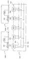
- the power supply unit 100 includes a voltage converter 110, a frequency converter 120, a control unit 130, a power patch (M), the portable device 200 ) Includes a charging contact N, a rectifier 210, a voltage converter 220, and a rechargeable battery 230.
- the operation of the system of FIG. 1 is as follows.
- the plurality of power patches M of the power supply unit 100 to which the charging power is applied, and the charging contact N of the mobile device 200 are stored in a non-contact state.
- the AC power for charging of the power supply unit 100 is applied to the portable device 200 side, and the AC power applied in this way rectified in the rectifier 210, after converting in the voltage converter 220, It is a charging system of the type used in the rechargeable battery 230.
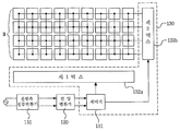
- FIG. 2 is a block diagram showing a structure of a power supply side of a conventional capacitively coupled charging system.
- a conventional apparatus was powered using a first mux 132a and a second mux 132b controlled by the controller 131.
- a contact charging system for charging the power supply unit M of the power supply unit 100 and the charging contact N of the portable device 200 to be in direct contact with each other is also proposed.
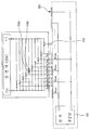
- FIG. 3 is a circuit diagram illustrating a charging device including a rectifier device to solve a polarity problem of a power patch.
- the charging device of FIG. 3 includes a plurality of charging contacts 303 connected with a plurality of power patches 302 and a rechargeable battery 314 for storing electrical energy.
- the charging contact 303 is connected to the rechargeable battery 314 through a plurality of diodes (315a, 315b).
- the Y05 contact may be connected to the '+' pole of the rechargeable battery 314 through the first diode 315a, and the power applied to the Y05 contact may be When the polarity is '-', it may be connected to the '-' pole of the rechargeable battery 314 through the second diode 315b.
- connection structure between the conventionally proposed modules (for example, the charging module and the portable device module) is based on an electronic device, an additional configuration for controlling the electronic device is required, and problems of heat generation and power efficiency are required. Inevitably occurred.
- the present invention has been proposed to solve the above-mentioned problems of the prior art, and proposes an electrical connection system that performs electrical connection using the mechanical features of the module.
- Still another object of the present invention is to propose an electrical connection system capable of electrical connection without limiting the position of each module.
- Another object of the present invention is to propose an electrical connection system which is inexpensive and simple to manufacture.
- the electrical connection system proposes a first electric module and a second electric module in order to achieve the above object.
- the first electrical module has a contact surface, the concave and convex surface of the concave surface and concave surface arranged on the contact surface is provided, the first electrical connection is formed on the concave surface, the first surface on the concave surface
- a second electrical contact is provided that is insulated from the first electrical contact, wherein the second electrical contact includes a ferromagnetic portion, wherein the first electrical contact and the second electrical contact comprise a first electrical module load provided in the first electrical module.
- the second electrical module having a mounting surface corresponding to the contact surface, wherein the mounting surface has a flat portion and a plurality of holes, and the plurality of holes are recessed electrode units.
- the electrode pin is configured to be installed, and when the magnetic force is not applied to the ferromagnetic portion of the first electric module, the electrode is in the retracted position, and when the magnetic force is applied, the electrode is switched to the protruding position. Further comprises a magnet.
- a conductive patch commonly connected to a first pole of the second electrical module is formed on at least a portion of the flat part surface, and the electrode pin is commonly connected to a second pole of the second electrical module.
- the electrode pins are insulated from each other, and when the electrode pins correspond to the second electrical connection portion of the first electrical module, the second pole of the second electrical module is connected to the second electrode of the first electrical module through the electrode pins. It protrudes so as to be connected to an electrical connection, and the first pole of the second electrical module is connected to the first electrical connection of the first electrical module through the conductive patch.
- the first electrical module is provided with a contact surface, provided with an uneven surface consisting of a concave surface and concave surface arranged on the contact surface, the first electrical connection on the iron surface And a second electrical connection portion is formed on the concave surface, the second electrical connection portion being insulated from the first electrical connection portion, the second electrical connection portion comprises a magnet, the first electrical connection portion and the second electrical connection portion being the first electrical module. It is connected to the first pole and the second pole of the first electrical module load provided in, respectively.
- the second electrical module has a mounting surface corresponding to the contact surface, wherein the mounting surface has a flat portion and a protrusion protruding from the flat portion, and at least a portion of the flat portion has a first pole of the second electrical module.
- a first conductive patch commonly connected to the second conductive patch, a second conductive patch corresponding to the second pole of the second electrical module is formed at an end of the protrusion, and the first conductive patch and the second conductive patch are insulated from each other. do.
- the second conductive patch and the second pole of the second electric module are short-circuited when a magnetic field is detected on the rear surface of the protrusion, and when the magnetic field is not detected, the second conductive patch and the second electric module are not formed.
- a magnetic sensing module for electrically opening the two poles is provided, and when the protrusion is accommodated in the concave surface and the magnetic sensing module senses a magnetic field, the first conductive patch is connected to the first electrical connection.
- the second conductive patch is connected to the second electrical connection portion.
- the first electrical module has a contact surface
- the first surface is provided with a first electrical connection with a magnet and a second electrical connection is insulated from the first electrical connection
- the first electrical connection part and the second electrical connection part are respectively connected to the first pole and the second pole of the first electric module load provided in the first electric module
- the second electric module has a mounting surface corresponding to the contact surface.
- the mounting surface is provided with a switching module having an external electrode and a magnetic sensing means corresponding to the electrical connection.
- the switching module short-circuits the first electrode of the external electrode and the second electric module when the magnetic field is detected by the magnetic sensing module, and when the magnetic field is not sensed by the magnetic sensing module,
- the second pole of the second electrical module is shorted and the first electrical contact is in contact with the external electrode, it is connected to the first pole of the second electrical module, and the second electrical contact is connected to the external electrode.
- the second pole of the second electrical module When in contact, it is connected to the second pole of the second electrical module.
- the first electrical module has a contact surface, the first electrical connection having a magnet for generating a magnetic field of a first polarity and the magnet for generating a magnetic field of a second polarity on the contact surface; And a second electrical contact portion having the first electrical contact portion and the second electrical contact portion insulated from each other, and wherein the first electrical contact portion and the second electrical contact portion are provided in the first electrical module.
- the second electrical module Connected to the first pole and the second pole, respectively, has a mounting surface corresponding to the contact surface, the mounting surface is provided with a switching module having an external electrode and a magnetic sensing means corresponding to the electrical connection portion .
- the switching module may short-circuit the first electrode of the external electrode and the second electrical module when the magnetic field of the first polarity is detected by the magnetic sensing module, and the magnetic field of the second polarity may be shortened by the magnetic sensing module.
- the second electrode of the second electrode and the second electrode is short-circuited, and when the first electrical contact portion is in contact with the external electrode, the second electrode of the second electrode is connected to the first electrode of the second electrode, and the second electrode When the electrical contact portion is in contact with the external electrode is characterized in that it is connected to the second pole of the second electrical module.
- the first electrical module has a contact surface, but generating at least one first electrical connection portion and a magnetic force of the second polarity having a magnet for generating a magnetic force of a first polarity on the contact surface;
- a first electrical module is provided with a second electrical connection having a magnet, wherein the first electrical connection and the second electrical connection are insulated from each other, and the first electrical connection and the second electrical connection are provided in the first electrical module.
- the second electrical module has a mounting surface corresponding to the contact surface, the mounting surface is provided with a plurality of holes, the plurality of holes of the first polarity
- a first electrode pin comprising a magnet of a second polarity and a magnetic force of the second polarity so as to be in a retracted position when no magnetic force is applied and to be switched to a protruding position when the magnetic force of the first polarity is exerted
- the second electrode pin is provided in the retracted position when it does not reach, and includes a magnet of the first polarity so as to be switched to the protruding position when the magnetic force of the second polarity is exerted, and the first and second electrode pins
- the second electrical connecting portion corresponds to the hole in which the second electrode pin is installed
- the second electrical connecting portion is connected to the first pole of the second electrical module and the second electrical module is connected to the first electrode of the second electrical module. It is characterized by being connected to two poles.
- the first electrical module has a contact surface, the first electrical connection having a magnet for generating a magnetic force of a first polarity on the contact surface, the first electrical connection is insulated and the second A second electrical contact portion having a magnet for generating a magnetic force of polarity, a third electrical contact portion insulated from the first and second electrical contact portions, wherein the first to third electrical contact portions are provided with a first electrical load of the first electrical module load;
- the second electrical module is connected to the third pole, respectively, the second electrical module has a mounting surface corresponding to the contact surface, on the mounting surface is provided with a plurality of switching modules each having three external electrodes.
- the switching module protrudes a first external electrode which is one of the external electrodes when a magnetic force of a first polarity is applied, and protrudes a second external electrode which is the other one of the external electrodes when a magnetic force of a second polarity is applied.
- the third external electrode which is another one of the external electrodes, protrudes, and the first to third external electrodes are connected to the first to third electrodes of the second electrical module, respectively.
- the first electrical contact corresponds to the switching module
- the second electrical contact corresponds to the switching module
- the second electrical contact is connected to the second pole of the second electrical module via a second external electrode
- the third electrical contact corresponds to a switching module
- the third of the second electrical module through the third external electrode. Electrical connection system, characterized in that connected to the pole.
- the electrical connection system according to the present invention can be applied to various systems such as a charging device for a portable device and a data communication device for a portable device.
- the electrical connection system When using the electrical connection system according to the present invention, there is an advantage that the electrical connection is possible regardless of the position of each module. For example, when the present invention is applied to a charging device of a portable device, since the charging is possible regardless of the location of the portable device, there is an advantage that the charging is conveniently performed.
- FIG. 2 is a block diagram showing a structure of a power supply side of a conventional capacitively coupled charging system.
- FIG. 3 is a circuit diagram illustrating a charging device including a rectifier device to solve a polarity problem of a power patch.
- FIG. 4 is a cross-sectional view illustrating an electrical connection system according to a first embodiment of the present invention.
- FIG 6 is another example showing the shapes of the first electrical module and the second electrical module.
- FIG. 12 is a cross-sectional view illustrating an electrical connection system according to a second embodiment of the present invention.
- FIG. 13 illustrates a magnetic sensing module included in the second electrical module 700.
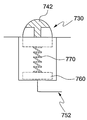
- FIG. 14 is a diagram illustrating an example of a structure in which the protrusion 730 of the second electric module moves in the vertical direction.
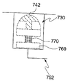
- FIG. 15 is a diagram illustrating still another example of a structure in which the protrusion 730 of the second electric module moves in the vertical direction.
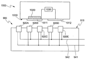
- 16 is a cross-sectional view illustrating an electrical connection system according to a third embodiment of the present invention.
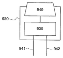
- 17 is a diagram illustrating an example of the switching module 920.
- 19 is another example of a modified structure of the switching module.
- FIG. 21 shows a structure in which the first electrical module and the second electrical module are connected through three different types of electrical connections.
- FIG. 23 is a cross-sectional view illustrating an electrical connection system according to a fifth embodiment of the present invention.
- 24 and 25 are examples of electrode pins.
- 26 is a cross-sectional view illustrating an electrical connection system according to a sixth embodiment of the present invention.
- FIG. 27 is a diagram illustrating a specific example of the switching module 1530.
- FIG. 31 is a diagram illustrating a second electrical module electrically connected to different first electrical modules.
- This embodiment relates to an electrical connection system between a first electrical module and a second electrical module on which the first electrical module is mounted.
- the first electrical module or the second electrical module may be any kind of module including an electrode and a data terminal.
- the first electrical module or the second electrical module may be a mobile phone, a portable mp3 player, an adapter for power supply, or a data signal source for supplying a data signal.
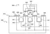
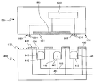
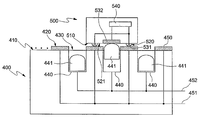
- FIG. 4 is a cross-sectional view illustrating an electrical connection system according to a first embodiment of the present invention.
- the first electrical module 500 has a contact surface 510, and has a concave surface 521 and an iron surface 520 arranged on the contact surface 510.
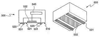
- the shape of the concave surface 521 and the convex surface 520 is not limited, and as shown, the cross section may have a hemispherical shape, a trapezoidal shape, or a strip shape in the horizontal or vertical direction on the contact surface 510. Can be.
- the convex surface 520 has at least one first electrical contact 531, and the concave surface 521 has at least one second electrical contact 532.
- the first electrical contact portion 531 may be formed over part or all of the iron surface 520.
- the second electrical connector 532 may be formed over the entirety of the concave surface 521 or only a portion thereof.
- At least one of the first electrical connection part 531 and / or the second electrical connection part 532 may be formed.
- the 1st electrical connection part 531 formed in multiple numbers was connected in common.
- first electrical contact 531 and the second electrical contact 532 is insulated from each other in order to prevent a short between the electrical contact.
- the second electrical contact 532 comprises a ferromagnetic portion.
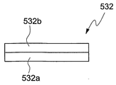
- the ferromagnetic part may be included as a separate member 532b on the rear surface of the conductive member 532a or may be formed of a conductive and ferromagnetic material.
- the first and second electrical connections 531, 532 are connected to first and second poles of the first electrical module load 540, respectively.
- the first electrical module load 540 refers to various types of electrical modules, and may be, for example, a battery, an electronic circuit board, a USB module, a motor, a power supply module, and the like.
- the first electrode or the second electrode is an electrode classified into various electrical characteristics. For example, the first pole and the second pole may be distinguished by a potential difference applied to the electrode.
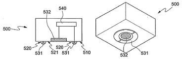
- FIG 6 is another example showing the shapes of the first electrical module and the second electrical module. As shown, the sizes of the first electrical module 500 and the second electrical module 400 may be variously manufactured.
- a circular second electrical contact portion 532 is formed on the concave surface provided in the first electrical module 500, and an iron surface is formed on the annular protrusion formed around the second electrical contact portion 532.
- the first electrical connecting portion 531 may be formed on the iron surface.
- first electrical contact 531 and the second electrical contact 532 may be in the form of a protruding strip.
- At least one concave and concave surfaces may be appropriately disposed to form concave-convex surfaces.
- the second electrical module 400 that mounts the first electrical module 500 includes a mounting surface 410 opposite to the contact surface 510, as shown.
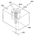
- the mounting surface 410 has a flat portion 420 and a plurality of holes 430.
- the plurality of holes 430 includes a recessed electrode unit 440, and each of the recessed electrode units 440 includes an electrode pin 441.
- the electrode pin 441 may be made of a conductive magnet, or may be manufactured in a form in which the conductive metal part and the magnet are separately separated. Since the electrode pin 441 includes a magnet, the second electrical connection part 532 including the ferromagnetic part may protrude when the electrode pin 441 is adjacent to the electrode pin 441. That is, the electrode pin 441 is usually recessed, but preferably has a feature that protrudes when the magnetic force is applied.
- the magnetic force when the magnetic force is applied, it means that the effective magnetic force of the predetermined threshold value or more, and when the magnetic force does not reach, it means that the magnetic force below the predetermined threshold value.
- At least one conductive patch 450 is formed on at least part of the surface of the flat part 420.
- the conductive patch 450 may be commonly connected to the first electrode 451 of the second electrical module 400, and the electrode pin 441 may be connected to the second electrode 452 of the second electrical module. It is preferable to connect in common.
- the conductive patch 450 and the electrode pin 441 are insulated from each other.
- the recessed electrode unit 440 may be manufactured in various ways.
- the recessed electrode unit 440 includes a magnetic core 441a formed of a magnet in the center thereof, and an outer portion of the conductive member 441b. It may include an electrode pin having a.
- the conductive member 441b is preferably electrically connected to the elastic member 460.
- the recessed electrode unit 440 may include an electrode pin formed integrally with a conductive magnet, unlike the example of FIG. 9. In the case of the electrode pin of FIG. 9, when the ferromagnetic material approaches from the outside, it protrudes, and when the ferromagnetic material moves away from the outside, it is discharged by the elastic member 460.
- the electrode pin 441 protrudes due to the attraction force between the electrode pin 441 and the ferromagnetic portion included in the second electrical connection part 532.
- the ferromagnetic portion included in the second electrical connecting portion 532 it is also possible to magnetize the ferromagnetic portion included in the second electrical connecting portion 532 to operate like a magnet, in this case, the polarity of the electrode pin 441 and the ferromagnetic included in the second electrical connecting portion 532 It is desirable to vary the polarity between the sexes.
- the 'N' pole may be positioned at an end of the electrode pin 441, and the ferromagnetic portion may be magnetized such that the 'S' pole is positioned at an opposite side of the ferromagnetic portion.
- the first pole 451 of the second electrical module corresponds to the first electrical connector 531 of the first electrical module
- the second pole 452 of the second electrical module is formed of the first electrical module. 2 corresponds to the electrical connection 532.
- the first electrical connection 531 is also a VCC terminal
- the second pole of the second electrical module is When 452 is a ground (GND) terminal, the second electrical connection 532 may also be a ground terminal.
- the second electrical module 400 and the first electrical module 500 proposed in this embodiment are electrically connected to each other due to the illustrated structure.
- FIG. 10 shows an example in which the electrode pins of the second electrical module correspond to certain surfaces of the first electrical module.
- the electrode pin ( 441 is received on the concave surface 521.
- the second electrode 452 of the second electrical module is connected to the second electrical connector 532 through the protruding electrode pin 441.
- first electrical connector 531 of the first electrical module 500 comes into contact with the conductive patch 450 of the second electrical module 400, and as a result, the first pole ( 451 is connected with the first electrical connector 531 of the first electrical module, and the second pole 452 of the second electrical module is connected with the second electrical connector 532 of the first electrical module.
- connection part 531 and the electrode pin 441 do not contact each other. Therefore, the connection parts and electrode pins which do not electrically correspond to each other are not connected to each other.
- the first electrode 451. May be a charging power terminal having a predetermined potential (for example, '5' volts), and the first electrical connection 531 may be a VCC terminal of a battery.
- the second electrode 452 and the second electrical connector 532 may be a GND terminal having a ground potential.
- the shape and arrangement of the concave surface 521 and the convex surface 520 included in the first electrical module 500 are appropriately adjusted, and the shape and arrangement of the first electrical connecting portion 531 and the second electrical connecting portion 532.
- the electrical connection can be established at all times regardless of the position where the first electrical module 500 is mounted.
- optimizing the number and location of the electrode pins 441 and the conductive patches 450 of the second electrical module 400 may facilitate electrical connection with the first electrical module 500.
- the second electrical connector 532 of the first electrical module is large enough to cover the electrode pin 441 of the second electrical module, and the first electrical connector 531 of the second electrical module is also the second electrical module. It is preferably formed large so as to cover the conductive patch 450 in a wide area of the. That is, the size of the first and second electrical connections of the first electrical module is preferably formed larger than the pitch of the electrode pin 441 or the conductive patch 450 of the second electrical module 400.
- the second embodiment facilitates electrical connection between the first electrical module and the second electrical module by using a magnet as in the first embodiment.
- FIG. 7 is a cross-sectional view illustrating an electrical connection system according to a second embodiment of the present invention.
- the first electrical module 800 has a contact surface 810 and has a concave surface 830 and an iron surface 820 that are repeatedly arranged on the contact surface 810. As described above, the shape of the convex surface 820 may be freely determined.
- the convex surface 820 has at least one first electrical contact 841, and the concave surface 830 has at least one second electrical contact 842.
- the first electrical contact 841 may be formed over part or all of the iron surface 820.
- the second electrical connector 842 may be formed over the entirety of the concave surface 830, or only a portion thereof.
- the concave surface 830 is preferably provided with a second electrical connection 842 provided with a magnet 850.
- the first electric module 800 according to the second embodiment generates a magnetic field by the magnet 850, and the second electric module 700 senses the magnetic field to electrically connect the modules 700 and 800. Connect with
- the second electrical connection part 842 including the magnet may be integrally formed by a conductive member having magnetic properties, or may be formed to separate the conductive member and the magnet layer.
- first electrical contact 841 and the second electrical contact 842 are each commonly connected.
- first electrical contact 841 and the second electrical contact 842 are insulated from each other to prevent a phenomenon such as a short between the electrical contacts.
- the first and second electrical connections 841 and 842 are connected to first and second poles of the first electrical module load 860, respectively.
- the first electrical module load 860 refers to various types of electrical modules as in the case of the first embodiment.
- the uneven surface of the first electrical module 800 may be manufactured in various ways.
- the shapes shown in FIGS. 7 and 8 are also applicable to the second embodiment.
- the second electrical module 700 that mounts the first electrical module 800 has a mounting surface 710 facing the contact surface 810, as shown.
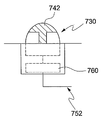
- the mounting surface 710 has a flat portion 720 and a plurality of protrusions 730. At least one first conductive patch 741 is formed on all or part of the surface of the flat portion 720. As illustrated, a plurality of first conductive patches 741 may be repeatedly formed. A second conductive patch 742 is formed at the end of the protrusion 730. The first conductive patch 741 and the second conductive patch 742 are insulated from each other.
- the first conductive patch 741 is commonly connected to the first electrode 751 of the second electrical module 700, and the second conductive patch 742 is connected to the second electrical module 700. It is preferable to be connected to the second electrode 752 in common.
- FIG. 13 illustrates a magnetic sensing module included in the second electrical module 700.
- the magnetic sensing module 760 is further provided on the rear surface of the protrusion 730 of the second electric module 700 according to the second embodiment to sense magnetic force and perform on / off switching according to the detected result.
- the magnetic sensing module 760 may be implemented through a hall sensor, which is a transistor for sensing a magnetic field, and an on / off switch for controlling an electrical short / opening according to a sensing result of the hall sensor.
- the magnetic sensing module 760 may detect an effective magnetic field having a magnitude greater than or equal to a threshold, and may not detect a magnetic field having magnitude less than the threshold.
- the magnetic sensing module 760 may be implemented through a reed switch manufactured in a form in which a plurality of ferromagnetic leads are encapsulated in a glass tube.
- the reed switch is a switch for shorting / opening an electrical connection according to the presence / absence of a magnetic field or the presence or absence of a specific polarity ('N' pole, 'S' pole).
- the magnetic sensing module 760 When the magnetic field is detected by the magnetic sensing module 760, the magnetic sensing module 760 short-circuits the second conductive patch 742 and the second pole 752 of the second electrical module, and the magnetic field is shorted. If not detected, the magnetic sensing module 760 opens the second conductive patch 742 and the second pole 752 of the second electrical module.
- the first pole 751 of the second electrical module corresponds to the first electrical contact 841 of the first electrical module
- the second pole 752 of the second electrical module is formed of the first electrical module. 2 corresponds to electrical connection 842.
- the first electrical connection 841 is also a VCC terminal
- the second pole of the second electrical module is When 752 is a ground (GND) terminal, the second electrical connection 842 may also be a GND terminal.
- the second electrical module 700 and the first electrical module 800 according to the second embodiment are electrically connected between the modules 700 and 800 due to the illustrated structure.
- the protrusion 730 since the rear surface of the concave surface 830 includes a magnet 850, when the protrusion 730 of the second electrical module 700 is accommodated in the concave surface 830, the protrusion 730.
- the magnetic sensing module 760 located at the bottom may detect the magnetic field. That is, when the magnetic field is detected by the magnetic sensing module 760, since the protrusion 730 is located on the concave surface 830, the second pole 752 and the second of the second electrical module are located.
- the conductive patch 742 is shorted to connect the second electrical module 700 and the first electrical module 800.
- the magnetic sensing module 760 does not detect the magnetic field, the protrusion 730 may not be located on the concave surface 830.
- the pole 752 and the second conductive patch 742 are opened.
- the first electrical connection 841 of the first electrical module 800 is the first conductive patch 741 of the second electrical module 700.
- the second electrical module 700 and the first electrical module 800 are electrically connected completely.
- the protrusion 730 of the second electrical module 700 may move in the direction perpendicular to the contact surface 710. Due to the tolerance of the contact surface 710 or the mounting surface 810, each of the electrical modules (700, 800) may not be in full contact, so that the protrusion 730 is moved in the vertical direction of the contact surface 710 It is preferable.
- FIG 14 is a diagram illustrating an example of a structure in which the protrusion 730 of the second electric module moves in the vertical direction. As illustrated, when the elastic member 770 is additionally inserted, the protrusion 730 may be moved in the vertical direction.
- FIG. 15 is a diagram illustrating still another example of a structure in which the protrusion 730 of the second electric module moves in the vertical direction. As shown, the protrusion 730 is formed in a recessed type, it may protrude only when there is a magnetic force from the outside.
- the first conductive patch formed on the second electrical contact portion 842 formed on the concave surface 830 or the flat portion 720 ( 741 may be formed of an electrically conductive member having elasticity.
- the third embodiment relates to a system for electrically connecting the first electrical module and the second electrical module using a magnetic field as in the first to second embodiments.
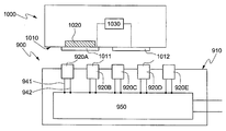
- 16 is a cross-sectional view illustrating an electrical connection system according to a third embodiment of the present invention.
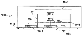
- the first electrical module 1000 has a contact surface 1010. At least one first electrical contact 1011 and at least one second electrical contact 1012 are provided on the contact surface 1010. Although the illustrated first electrical connecting portion 1011 and the second electrical connecting portion 1012 are manufactured in a plate shape, they may be manufactured in shapes having various three-dimensional shapes.
- first and second electrical connections 1011, 1012 are connected to first and second poles of the first electrical module load 1030, respectively.
- the first electrical module load 1030 refers to various types of electrical modules, as in the case of the first embodiment.
- first electrical contact 1011 and the second electrical contact 1012 are insulated from each other in order to prevent a short phenomenon between the electrical contact.
- a magnet 1020 may be provided on the rear surface of the first electrical connector 1011, or the magnet and the first electrical connector 1011 may be integrally formed.
- the magnetic field formed by the first electrical module 1000 provides information as to whether the electrical connection of the first electrical module 1000 is the first electrical connection 1011. That is, the second electrical module 900 identifies whether the first electrical contact portion 1011 is adjacent through the presence or absence of a magnetic field by the magnet 1020.
- the second electrical module 900 senses a magnetic field generated from the magnet 1020 and accordingly controls an electrical connection between the modules 900 and 1000.
- the second electrical module 900 that mounts the first electrical module 1000 has a mounting surface 910 facing the contact surface 1010, as shown.
- a plurality of switching modules 920 including an external electrode and a magnetic sensing module are provided on the mounting surface 910.
- the external electrode of the switching module 920 is a conductive patch through which the electrical connections 1011 and 1012 of the first electrical module 1000 are mounted.
- the external electrode may be manufactured in a plate shape or various three-dimensional shapes.
- the switching module 920 includes at least one external electrode 940 exposed to the outside and a magnetic sensing module 930 that can be implemented by a hall sensor.
- the switching module 920 shorts the first electrode 941 of the external electrode 940 and the second electrical module, and senses a magnetic field around the magnetic sensor module 930. If not, it is preferable to perform a switching operation of shorting the external electrode 940 and the second electrode 942 of the second electrical module.
- the magnetic sensing module 930 may be implemented through various devices.
- the magnetic sensing module 930 may be implemented by the above-described reed switch.
- it can be implemented as a hall sensor.
- the first pole 941 of the second electrical module corresponds to the first electrical connection 1011 of the first electrical module
- the second pole 942 of the second electrical module is the first electrical module of the first electrical module. 2 corresponds to the electrical connection 1012.
- the first pole 941 of the second electrical module is a VCC terminal of '+5 volts'
- the first electrical connection 1011 is also a VCC terminal
- the second pole of the second electrical module is If 942 is a ground (GND) terminal, the second electrical contact 1012 may also be a ground terminal.
- GND ground
- Both modules 900 and 1000 according to the third embodiment are electrically connected between the respective modules 900 and 1000 regardless of the position in which the first electrical module 1000 is mounted due to the illustrated structure.
- the first electrical module 1000 may be located at various places on the mounting surface 910.
- the third switching module because the magnetic sensing module included in the third switching module 920C senses a magnetic field.
- the external electrode of 920C and the first electrode 941 of the second electrical module will be shorted.
- the first electrical contact 1011 is connected to the first pole 941 of the second electrical module through the third switching module 920C.
- the fifth switching module 920E since the magnetic sensing module included in the fifth switching module 920E does not detect the magnetic field, the fifth The external electrode of the switching module 920E and the second pole 942 of the second electrical module will be shorted. Thus, the second electrical contact 1012 is connected to the second pole 942 of the second electrical module through the fifth switching module 920E.
- the number of the first and second electrical connections can be freely determined.
- each of the electrical connecting portions is preferably connected in common.
- the spacing between the first and second electrical connections can be freely determined.
- both modules 900 and 1000 may be always electrically connected regardless of the position of the first electrical module 1000.
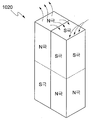
- 18 is an example of a magnet 1020 included in the first electrical module.
- the magnetic field generated by the magnet 1020 exists to an excessively long distance, a malfunction may occur in the switching module 920. Therefore, it is preferable that the magnetic field generated by the magnet 1020 drops at a close distance, but rapidly decreases when it moves away from the predetermined distance.
- 18 illustrates an example in which magnets are arranged in a form in which different polarities face each other in order for the magnet 1020 to have the aforementioned characteristics.
- FIG. 18 can be used for all the magnets used in the present invention as well as the third embodiment described above.
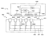
- FIG. 19 is another example of a modified structure of the switching module.
- the surrounding magnetic field is sensed, and a control signal related to the detected result is transmitted to the switching module 950 located therein. That is, the externally located switching module only detects the magnetic field and transmits a control signal, and does not perform the actual switching, and the actual switching may be performed by the switching module 950 located therein.
- the switching module 950 located therein may be implemented through various electronic devices such as a BJT and a MOSFET.
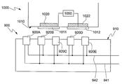
- the fourth embodiment is an example of adjusting the polarity of the magnet included in the first electrical module 1000 of the third embodiment.
- first electrical connecting portion 1011 of the first electrical module 1000 includes the magnet 1020.
- magnets are provided in both the first electrical contact 1011 and the second electrical contact 1012.
- the switching module 920 detects the presence or absence of the magnetic field. In the fourth embodiment, since the magnetic fields having different polarities are generated, the fourth embodiment is implemented. The example switching module 920 senses the polarity of a particular magnetic field.
- the switching module 920 of the fourth embodiment short-circuits the external electrode and the first pole 941 of the second electrical module.
- the magnetic field of the second polarity eg, the 'S' pole
- the external electrode and the second pole 942 of the second electric module are short-circuited.
- FIG. 21 shows a structure in which the first electrical module and the second electrical module are connected through three different types of electrical connectors 1011, 1012, and 1013.
- the first electrical contact 1011 has a magnet that generates a magnetic field of a first polarity
- the second electrical contact 1012 is formed of a first electrical contact 1012. It is preferable to have a magnet for generating a magnetic field of bipolarity, and the third electrical connection 1013 does not have a magnet.
- the first electrical contact 1011 is connected to the first pole 1051 of the first electrical module load 1050, and the second electrical contact 1012 is connected to the second pole (1) of the first electrical module load 1050.
- the third electrical contact 1013 is connected to a third pole 1053 of the first electrical module load 1050.
- the first electrical module load 1050 shown in FIG. 21 preferably includes two loads.
- the first load 1040 may be a battery
- the second load 1030 may be a data transmission / reception module. Even if two loads 1030 and 1040 are included, when one pole is connected in common, the input / output of an electric signal is possible through the three electrodes 1051, 1052 and 1053. Accordingly, in the case of the two loads 1030 and 1040 included in the illustrated first electric module load 1050, it is preferable to connect one electrode in common.
- the first to third electrodes 1051, 1052, and 1053 may input and output electrical signals that are electrically distinguished, such as potentials.
- the first electrode 1051 may be a ground electrode GND
- the second electrode 1052 may be a '+5 volt' electrode
- the third electrode 1053 may be a '+12 volt' electrode. Can be.
- the switching module 960 of the second electrical module 900 of FIG. 21 is preferably implemented through a Hall sensor capable of detecting the polarity of the magnetic field, and has a first polarity (eg, an 'N' pole).
- a magnetic field is detected, the external electrode and the first electrode 941 of the second electric module are short-circuited, and when a magnetic field having a second polarity (for example, 'N' pole) is detected, the external electrode and the second electric module are detected.
- the second electrode 942 may be shorted, and when the magnetic field is not detected, the external electrode and the third electrode 943 of the second electric module may be shorted.
- first to third poles 941, 942 and 943 of the second electric module correspond to the first to third electric connectors 1011, 1012 and 1013 of the first electric module, the above-described structure
- the first electrical module and the second electrical module can be connected.
- FIG. 22 shows another example of disposing two loads 1030 and 1040 included in the first electrical module load 1050. As shown, the two loads 1030 and 1040 may be arranged freely.
- the fifth embodiment relates to a system for electrically connecting the first electrical module and the second electrical module using a magnetic field as in the above-described embodiment.
- FIG. 23 is a cross-sectional view illustrating an electrical connection system according to a fifth embodiment of the present invention.
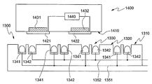
- the first electrical module 1400 has a contact surface 1410. At least one first electrical contact 1421 and at least one second electrical contact 1422 are provided on the contact surface 1410. Although the illustrated first electrical contact portion 1421 and the second electrical contact portion 1422 are manufactured in a plate shape, they may be manufactured in a shape having various three-dimensional shapes as in the above-described embodiments.
- first and second electrical connections 1421 and 1422 are connected to first and second poles of the first electrical module load 1440, respectively.
- the first electrical module load 1440 may be various types of electronic modules as in the above-described embodiment.
- the first electrical contact portion 1421 and the second electrical contact portion 1422 are insulated from each other.
- the first electrical contact 1421 and the second electrical contact 1422 have magnets.
- the magnet may be integrally formed with the electrical connection or separately provided on the rear surface of the connection.
- the first magnet 1431 provided on the rear surface of the first electrical connection portion 1421 has a first polarity
- the second magnet 1432 provided on the rear surface of the second electrical connection portion 1422 is the first magnet. To be distinguished from the magnet, it is preferred to have a second polarity.
- the second electrical module 1300 senses the magnetic fields generated from the first and second magnets 1431 and 1432, and thus controls the electrical connection between the modules 1300 and 1400.
- the second electrical module 1300 mounted on the first electrical module 1400 has a mounting surface 1310 opposite to the contact surface 1410, as shown.
- the flat surface 1320 and the plurality of holes 1330 are provided on the mounting surface 1310.
- the plurality of holes are provided with a first electrode pin 1341 and a second electrode pin 1342, respectively. As shown, it is preferable that one electrode pin is provided in one hole 1330, and the first electrode pin 1341 and the second electrode pin 1342 are alternately provided with each other.
- the first electrode pin and the second electrode pin of the fifth embodiment protrude when the magnetic force above the predetermined threshold is applied and exit when the magnetic force below the threshold is applied.
- the first electrode pin 1341 may include a magnet of a second polarity in order to protrude by the magnetic force of the first magnet 1431 having the first polarity.
- the magnet of the second polarity is positioned on the side facing the contact surface 1410.
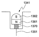
- An example of the first electrode pin 1341 may be the same as that of FIG. 24.
- the first electrode pin 1341 is manufactured so that the second polar portion 1362 of the magnet protrudes outward, and the first polar portion 1361 of the magnet faces the opposite direction. Can be made.
- the second electrode pin 1342 preferably includes a magnet of the first polarity to protrude by the magnetic force of the second magnet 1432 having the second polarity.
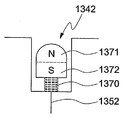
- An example of the second electrode pin 1342 is illustrated in FIG. 25. As shown in FIG. 25, the second electrode pin 1342 is manufactured so that the first polar portion 1372 of the magnet protrudes to the outside, and the second polar portion 1372 of the magnet faces the opposite direction. Can be made.
- the first electrode pin 1341 may protrude or exit. Specifically, when the magnetic force of the first magnet (1431) is applied to the first electrode pin (1341), the first electrode pin (1341) is switched to the protruding position, the magnetic force of the first magnet (1431) When it does not reach the first electrode pin 1341, the first electrode pin 1341 is switched to the exit position.
- the elastic member 1370 is also connected to the second electrode pin 1342, when the magnetic force of the second magnet 1432 applies to the second electrode pin 1342, the second electrode pin 1342 is When it is switched to the protruding position and the magnetic force of the second magnet 1432 does not reach the second electrode pin 1342, the second electrode pin 1342 is switched to the retracted position.
- the electrode pins 1341 and 1342 are preferably positioned behind the flat portion 1320 in a state in which magnetic force is not applied.
- Electrodes 24 and 25 are only various examples of the electrode pins 1341 and 1342, and thus, specific structures of the electrode pins 1341 and 1342 may be modified.
- the electrode pins 1341 and 1342 are formed in plural, and the plurality of first electrode pins 1341 are commonly connected to the first pole 1351 of the second electrical module, and the plurality of second electrode pins 1342 ) Is commonly connected to the second pole 1352 of the second electrical module.
- the first pole 1351 of the second electrical module corresponds to the first electrical connection 1421 of the first electrical module
- the second pole 1352 of the second electrical module is formed of the first electrical module. 2 corresponds to the electrical connection 1422.
- the first pole 1351 of the second electrical module is a VCC terminal of '+5 volts'
- the first electrical connection 1421 is also a VCC terminal
- the second pole of the second electrical module is
- 1352 is a ground (GND) terminal
- the second electrical contact 1422 may also be a ground terminal.
- Both modules 1300 and 1400 according to the fifth embodiment may be electrically connected between the modules 1300 and 1400 regardless of a location where the first electrical module 1300 is mounted due to the illustrated structure.
- the first electrical module 1400 may be located at various locations on the mounting surface 1310.
- a first electrode pin 1342 protrudes due to a magnetic force generated from the first magnet 1431, so that the first electrical connection part 1421 and the first electrode pin ( 1341) makes contact.
- the second electrode pin 1342 protrudes by a magnetic force generated from the second magnet 1432 provided on the rear surface of the second electrical contact portion 1422.
- a second electrical contact 1422 is in contact with the second electrode pin 1342.
- the first electrical contact 1421 is connected to the first pole 1351 of the second electrical module, and the second electrical contact 1422 is connected to the second pole 1352 of the second electrical module. Connected, an electrical connection is made between both modules 1300 and 1400.
- the sixth embodiment relates to a system for electrically connecting the first electrical module and the second electrical module using a magnetic field as in the above-described embodiment.
- 26 is a cross-sectional view illustrating an electrical connection system according to a sixth embodiment of the present invention.
- the first electrical module 1600 has a contact surface 1610.
- a first electrical contact 1621 and a second electrical contact 1622 are provided on the contact surface 1610.
- the electrical connections 1621 and 1622 have various three-dimensional shapes as well as plates.
- the first electrical module 1600 has a first electrical module load 1670.
- the first electrical connecting portion 1621 and the second electrical connecting portion 1622 are provided with magnets.
- the first magnet 1631 provided in the first electrical connecting portion 1621 has a first polarity and is a second magnet provided in the second electrical connecting portion 1622.
- 1632 preferably has a second polarity to distinguish it from the first magnet.
- the second electrical module 1500 may identify each electrical connection through a magnetic field generated from the first electrical module 1600.
- the first electrical contact 1621 is identified when the magnetic field of the first polarity is identified, and the second electrical contact 1622 is identified when the magnetic field of the second polarity is identified.
- the second electrical module 1500 that mounts the first electrical module 1600 has a mounting surface 1510 that faces the contact surface 1610, as shown.
- a plurality of switching modules 1530 including external electrodes are provided on the mounting surface 1510.
- the external electrode of the switching module 1530 is a conductive patch through which the electrical connectors 1621 and 1622 of the first electrical module 1600 are mounted, and the external electrode may be manufactured in a plate shape or various three-dimensional shapes.
- the switching module 1530 switches the external electrode to the first pole 1541 or the second pole 1542 of the second electrical module.
- One switching module 1530 preferably includes two external electrodes. A first external electrode is connected to the first pole 1541 of the second electrical module, and the second external electrode is connected to the second pole 1542 of the second electrical module.
- the switching module 1530 exposes the first external electrode when the magnetic field of the first polarity is exposed, and exposes the second external electrode when the magnetic field of the second polarity is applied.
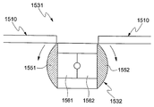
- the switching module 1530 may be implemented through a rotating member 1531 rotatably mounted to a hinge.
- the rotating member 1531 may further include an elastic member (not shown) formed along the rotation axis, or may be formed without the elastic member.
- the rotating member 1531 includes first to second external electrodes 1551 and 1552 exposed to the outside.
- a magnet 1561 of a second polarity is further provided on a rear surface of the first external electrode 1551
- a magnet 1562 of a first polarity is further provided on a rear surface of the second external electrode 1552.
- the first to second external electrodes 1551 and 1552 are connected to the first poles 1541 to 2154 of the second electrical module, respectively.
- the rotating member 1531 rotates in the forward or reverse direction about the rotation axis.
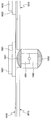
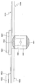
- 28-30 illustrate the operation of the second electrical module for sensing two poles.
- FIG. 28 shows an example in which the first electrical contact 1621 provided with the magnet 1631 having the first polarity is adjacent to the second electrical module.
- the rotating member 1531 rotates in the forward direction. That is, when the magnetic field of the first polarity is applied to the switching module 1530, the first external electrode 1551 is exposed.
- FIG. 29 shows an example in which the second electrical contact 1622 provided with the magnet 1632 having the second polarity is adjacent to the second electrical module.
- the rotating member 1531 rotates in the reverse direction. That is, when the magnetic field of the second polarity is applied to the switching module 1530, the second external electrode 1552 is exposed.
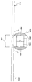
- FIGS. 28 to 29 is a view for explaining the advantages of the example of FIGS. 28 to 29.
- the rotating member is formed as illustrated in FIGS. 28 to 29, foreign matter is prevented from being inserted from the outside through the hole 1901 formed on the mounting surface 1510.
- the intervals between the respective electrical connections may be set in various ways, and may be spaced at sufficient intervals to prevent malfunctions.
- FIG. 31 is a diagram illustrating a second electrical module electrically connected to different first electrical modules.
- FIG. The illustrated second electrical module 1500 may be based on the example of FIG. 12B.
- 31 illustrates a second electrical module 1500 electrically connected to first electrical modules 1900A and 1900B having different loads 1640 and 1650.
- the illustrated first electrical module 1900A is provided with a first load 1640, and a first electrical contact 1621 and a third electrical contact 1623 are connected to both ends of the first load 1640.
- the magnet 1631 of the first polarity is provided on the rear surface of the first electrical connecting portion 1621.
- another illustrated first electrical module 1900B is provided with a second load 1650, and second and third electrical connections 1622 and 3223 are provided at both ends of the second load 1650. And a magnet 1632 of a second polarity is provided on a rear surface of the second electrical contact 1622.
- the second electrical module 1500 may be electrically connected to two first electrical modules 1900A and 1900B simultaneously.
- the first load 1640 may be an electronic module operating at a voltage of '+5' volts
- the second load 1650 may be an electronic module operating at a voltage of '+1' volts.
- the first electrical contact 1621 is a '+5' volt terminal
- the third electrical contact 1623 is a ground (GND) terminal
- the second electrical contact 1622 is a '+1' volt terminal. have.
- the switching module 1530 of the second electrical module 1500 is provided on the rear surface of the first electrical contact 1621 when the first electrical contact 1621, that is, the +5 volt terminal is adjacent to the switching module 1530.
- the magnet 1631 may be identified, and the '+5' bolt electrode provided in the first electrical connector 1621 and the second electrical module 1500 may be electrically connected.
- the switching module 1530 identifies that the magnetic field does not exist when the third electrical connector 1623, that is, the ground terminal 1623 is adjacent to each other, and the third electrical connector 1623 and the third electrical connector 1623. 2
- the ground electrode provided in the electrical module 1500 may be electrically connected.
- the switching module 1530 may include a magnet 1632 provided on the rear surface of the second electrical contact 1622 when the second electrical contact 1622, that is, the '+1' volt terminal 1622 is adjacent thereto.
- the second electrical connector 1622 and the '+1' bolt electrode provided in the second electrical module 1500 may be electrically connected.
Landscapes
- Details Of Connecting Devices For Male And Female Coupling (AREA)
- Connector Housings Or Holding Contact Members (AREA)
- Coupling Device And Connection With Printed Circuit (AREA)
Abstract
L'invention concerne une structure de connexion située entre des modules électroniques. Cette structure comprend plusieurs bornes et électrodes. En particulier, l'invention concerne un système de connexion électrique situé entre des modules électriques, qui permet d'établir facilement une connexion électrique entre les bornes et les électrodes situées dans lesdits modules électriques. Le système de connexion selon l'invention permet de relier un premier module électrique à un second module électrique. Plus particulièrement, l'invention est caractérisée en ce que: le premier module électrique présente une surface de contact ayant une surface irrégulière comportant des surfaces convexe et concave disposées sur ladite surface irrégulière; sur la surface convexe est formée une première partie de connexion électrique, et sur la surface concave est prévue une seconde partie de connexion électrique isolée de la première partie de connexion électrique, la seconde partie de connexion électrique comprenant une partie ferromagnétique; la première partie de connexion électrique et la seconde partie de connexion électrique sont respectivement reliées à une première électrode et à une seconde électrode d'une première charge de module électrique prévue pour le premier module électrique; le second module électrique présente une surface tactile correspondant à la surface de contact, la surface tactile présentant une partie plate et plusieurs orifices; dans ces orifices sont disposées des tiges d'électrodes comprenant une unité d'électrode en renfoncement, et les tiges d'électrodes contiennent également des aimants leur permettant d'adopter une position en retrait lorsque la partie ferromagnétique du premier module électrique ne subit pas de force magnétique, et de passer en position en saillie sous l'effet d'une force magnétique. En outre, des éléments conducteurs, reliés en commun à la première électrode du second module électrique, sont formés sur au moins une partie de la surface
Applications Claiming Priority (4)
| Application Number | Priority Date | Filing Date | Title |
|---|---|---|---|
| KR10-2008-0005725 | 2008-01-18 | ||
| KR20080005725 | 2008-01-18 | ||
| KR10-2008-0029163 | 2008-03-28 | ||
| KR1020080029163A KR100985908B1 (ko) | 2008-01-18 | 2008-03-28 | 전기 접속 시스템 |
Publications (2)
| Publication Number | Publication Date |
|---|---|
| WO2009091221A2 true WO2009091221A2 (fr) | 2009-07-23 |
| WO2009091221A3 WO2009091221A3 (fr) | 2009-10-29 |
Family
ID=40885817
Family Applications (1)
| Application Number | Title | Priority Date | Filing Date |
|---|---|---|---|
| PCT/KR2009/000260 Ceased WO2009091221A2 (fr) | 2008-01-18 | 2009-01-16 | Système de connexion électrique |
Country Status (1)
| Country | Link |
|---|---|
| WO (1) | WO2009091221A2 (fr) |
Cited By (2)
| Publication number | Priority date | Publication date | Assignee | Title |
|---|---|---|---|---|
| CN110581579A (zh) * | 2019-09-25 | 2019-12-17 | 橙意家人科技(天津)有限公司 | 一种生物监测用贴片的充电装置 |
| CN112006653A (zh) * | 2019-05-29 | 2020-12-01 | 华广生技股份有限公司 | 生物感测装置及生物感测装置启动方法 |
Family Cites Families (4)
| Publication number | Priority date | Publication date | Assignee | Title |
|---|---|---|---|---|
| KR20020080766A (ko) * | 2001-04-17 | 2002-10-26 | 신형진 | 자석을 이용한 전원접속기구 |
| KR20060005243A (ko) * | 2004-07-12 | 2006-01-17 | 주식회사 팬택앤큐리텔 | 단락 방지 기능을 가지는 전원공급장치 |
| KR20060018178A (ko) * | 2004-08-23 | 2006-02-28 | 주식회사 팬택 | 접점의 단락을 방지하는 스프링핀 커넥터 구조 및 그를구비한 이동통신 단말기 |
| US7467948B2 (en) * | 2006-06-08 | 2008-12-23 | Nokia Corporation | Magnetic connector for mobile electronic devices |
-
2009
- 2009-01-16 WO PCT/KR2009/000260 patent/WO2009091221A2/fr not_active Ceased
Cited By (2)
| Publication number | Priority date | Publication date | Assignee | Title |
|---|---|---|---|---|
| CN112006653A (zh) * | 2019-05-29 | 2020-12-01 | 华广生技股份有限公司 | 生物感测装置及生物感测装置启动方法 |
| CN110581579A (zh) * | 2019-09-25 | 2019-12-17 | 橙意家人科技(天津)有限公司 | 一种生物监测用贴片的充电装置 |
Also Published As
| Publication number | Publication date |
|---|---|
| WO2009091221A3 (fr) | 2009-10-29 |
Similar Documents
| Publication | Publication Date | Title |
|---|---|---|
| WO2016148470A1 (fr) | Procédé de génération de charge de récepteur de puissance sans fil dans un système de charge sans fil et récepteur de puissance sans fil | |
| WO2019164208A1 (fr) | Procédé et dispositif électronique pour commander une tension de sortie vers un dispositif électronique externe en fonction de la taille de tension détectée au niveau d'une borne de signal connectée à un dispositif électronique externe | |
| WO2014073863A1 (fr) | Dispositif récepteur de puissance sans fil et procédé de commande de puissance pour ce dernier | |
| WO2018186609A1 (fr) | Dispositif d'alimentation électrique | |
| WO2013105776A1 (fr) | Récepteur pour système de charge sans fil | |
| WO2016140534A1 (fr) | Boîtier pour terminal portable avec batterie intégrée | |
| WO2021157914A1 (fr) | Dispositif électronique pour stocker un dispositif électronique externe | |
| WO2017000216A1 (fr) | Circuit de commande de charge, dispositif de charge, système de charge et procédé de commande de charge | |
| WO2012173408A2 (fr) | Appareil de commande d'ensemble relais électrique et procédé de commande de celui-ci | |
| WO2023085616A1 (fr) | Dispositif de surveillance d'isolation et procédé de commande de dispositif de surveillance d'isolation | |
| WO2021241878A1 (fr) | Appareil d'affichage modulaire et procédé de commande associé | |
| WO2015182938A1 (fr) | Dispositif de communication et dispositif d'éclairage comprenant celui-ci | |
| WO2020096245A1 (fr) | Adaptateur et système électronique équipé de celui-ci | |
| WO2020076040A1 (fr) | Embase de connecteur | |
| WO2016140397A1 (fr) | Ensemble de montage de batterie et système de remplacement de batterie | |
| WO2019135608A1 (fr) | Appareil de transfert de signal optique, appareil électronique, dispositif source et procédés de fonctionnement correspondants | |
| WO2020111899A1 (fr) | Dispositif et procédé de commande de commutateur | |
| WO2021029608A1 (fr) | Mélangeur | |
| WO2021029606A1 (fr) | Mélangeur | |
| WO2019027144A1 (fr) | Système de diagnostic pour système électrique de véhicule ayant un convertisseur de tension cc-cc et un régulateur de tension | |
| WO2019088423A1 (fr) | Dispositif de commande de véhicule | |
| WO2015072701A1 (fr) | Dispositif boîtier pour batterie de forte capacité ayant une fonction de batterie auxiliaire pour terminal mobile | |
| WO2021137312A1 (fr) | Dispositif de charge sans fil apte à monter un terminal utilisateur dans diverses directions et divers angles | |
| WO2015147527A1 (fr) | Batterie, module de cellules et ensemble de modules de cellules | |
| WO2018135805A1 (fr) | Ensemble d'aimant de détection, appareil de détection de position de rotor et moteur le comprenant |
Legal Events
| Date | Code | Title | Description |
|---|---|---|---|
| 121 | Ep: the epo has been informed by wipo that ep was designated in this application |
Ref document number: 09702071 Country of ref document: EP Kind code of ref document: A2 |
|
| NENP | Non-entry into the national phase |
Ref country code: DE |
|
| 32PN | Ep: public notification in the ep bulletin as address of the adressee cannot be established |
Free format text: NOTING OF LOSS OF RIGHTS PURSUANT TO RULE 112(1) EPC |
|
| 122 | Ep: pct application non-entry in european phase |
Ref document number: 09702071 Country of ref document: EP Kind code of ref document: A2 |