WO2009093310A1 - Moteur à deux temps - Google Patents
Moteur à deux temps Download PDFInfo
- Publication number
- WO2009093310A1 WO2009093310A1 PCT/JP2008/050867 JP2008050867W WO2009093310A1 WO 2009093310 A1 WO2009093310 A1 WO 2009093310A1 JP 2008050867 W JP2008050867 W JP 2008050867W WO 2009093310 A1 WO2009093310 A1 WO 2009093310A1
- Authority
- WO
- WIPO (PCT)
- Prior art keywords
- scavenging passage
- passage
- mixed gas
- scavenging
- combustion chamber
- Prior art date
- Legal status (The legal status is an assumption and is not a legal conclusion. Google has not performed a legal analysis and makes no representation as to the accuracy of the status listed.)
- Ceased
Links
Images





Classifications
-
- F—MECHANICAL ENGINEERING; LIGHTING; HEATING; WEAPONS; BLASTING
- F02—COMBUSTION ENGINES; HOT-GAS OR COMBUSTION-PRODUCT ENGINE PLANTS
- F02F—CYLINDERS, PISTONS OR CASINGS, FOR COMBUSTION ENGINES; ARRANGEMENTS OF SEALINGS IN COMBUSTION ENGINES
- F02F3/00—Pistons
- F02F3/24—Pistons having means for guiding gases in cylinders, e.g. for guiding scavenging charge in two-stroke engines
-
- F—MECHANICAL ENGINEERING; LIGHTING; HEATING; WEAPONS; BLASTING
- F02—COMBUSTION ENGINES; HOT-GAS OR COMBUSTION-PRODUCT ENGINE PLANTS
- F02B—INTERNAL-COMBUSTION PISTON ENGINES; COMBUSTION ENGINES IN GENERAL
- F02B25/00—Engines characterised by using fresh charge for scavenging cylinders
- F02B25/14—Engines characterised by using fresh charge for scavenging cylinders using reverse-flow scavenging, e.g. with both outlet and inlet ports arranged near bottom of piston stroke
-
- F—MECHANICAL ENGINEERING; LIGHTING; HEATING; WEAPONS; BLASTING
- F02—COMBUSTION ENGINES; HOT-GAS OR COMBUSTION-PRODUCT ENGINE PLANTS
- F02B—INTERNAL-COMBUSTION PISTON ENGINES; COMBUSTION ENGINES IN GENERAL
- F02B25/00—Engines characterised by using fresh charge for scavenging cylinders
- F02B25/20—Means for reducing the mixing of charge and combustion residues or for preventing escape of fresh charge through outlet ports not provided for in, or of interest apart from, subgroups F02B25/02 - F02B25/18
- F02B25/22—Means for reducing the mixing of charge and combustion residues or for preventing escape of fresh charge through outlet ports not provided for in, or of interest apart from, subgroups F02B25/02 - F02B25/18 by forming air cushion between charge and combustion residues
-
- F—MECHANICAL ENGINEERING; LIGHTING; HEATING; WEAPONS; BLASTING
- F02—COMBUSTION ENGINES; HOT-GAS OR COMBUSTION-PRODUCT ENGINE PLANTS
- F02F—CYLINDERS, PISTONS OR CASINGS, FOR COMBUSTION ENGINES; ARRANGEMENTS OF SEALINGS IN COMBUSTION ENGINES
- F02F1/00—Cylinders; Cylinder heads
- F02F1/18—Other cylinders
- F02F1/22—Other cylinders characterised by having ports in cylinder wall for scavenging or charging
-
- F—MECHANICAL ENGINEERING; LIGHTING; HEATING; WEAPONS; BLASTING
- F02—COMBUSTION ENGINES; HOT-GAS OR COMBUSTION-PRODUCT ENGINE PLANTS
- F02B—INTERNAL-COMBUSTION PISTON ENGINES; COMBUSTION ENGINES IN GENERAL
- F02B75/00—Other engines
- F02B75/02—Engines characterised by their cycles, e.g. six-stroke
- F02B2075/022—Engines characterised by their cycles, e.g. six-stroke having less than six strokes per cycle
- F02B2075/025—Engines characterised by their cycles, e.g. six-stroke having less than six strokes per cycle two
Definitions
- the present invention relates to a two-cycle engine used for a small working machine such as a brush cutter or a blower.
- the two-cycle engine includes a piston slidably mounted in the cylinder, an exhaust passage communicating with the combustion chamber formed in the upper portion of the cylinder, and a scavenging passage communicating the combustion chamber and the crank chamber. .
- the mixed gas of fuel and air filled in the crank chamber flows into the combustion chamber through the scavenging passage, and the piston is moved into the cylinder by the expansion force when the mixed gas is burned in the combustion chamber. Is reciprocating.
- the combustion gas in the exhaust passage flows into the scavenging passage through the communication groove while the scavenging passage is blocked by the side surface of the piston, and burns to the combustion chamber side of the scavenging passage Gas stagnates.
- the scavenging passage opens to the upper part of the cylinder, the combustion gas staying in the scavenging passage flows into the cylinder ahead of the mixed gas. Therefore, in the scavenging stroke, the combustion gas that flows into the cylinder from the scavenging passage reaches the exhaust passage before the mixed gas that flows into the cylinder from the scavenging passage. The amount of hydrocarbons in the exhaust gas can be reduced.
- JP 11-287124 A (paragraph 0012, FIG. 1)
- the filling amount of the mixed gas into the cylinder is increased.
- the amount of combustion gas flowing into the cylinder from the scavenging passage is exhausted from the exhaust passage, and the amount of unburned mixed gas is reduced.
- the amount of unburned mixed gas exhausted from the exhaust passage increases, and the amount of hydrocarbons contained in the exhaust gas increases.
- an object of the present invention is to provide a two-cycle engine that solves the above-described problems and can significantly reduce the unburned gas contained in the exhaust gas and increase the output of the engine. .
- the present invention provides a first sweep that connects a piston that is slidably mounted in a cylinder, an exhaust passage that communicates with a combustion chamber formed in the cylinder, and a crank chamber and the combustion chamber.
- An air passage and a second scavenging passage, and a mixed gas of fuel and air filled in the crank chamber flows into the combustion chamber through each scavenging passage, and the mixed gas is burned in the combustion chamber, whereby the piston is cylinder
- the exhaust passage and the second scavenging passage are provided on the side surface of the piston with the exhaust passage and each scavenging passage blocked by the side surface of the piston.
- a communicating groove is formed, the first scavenging passage is provided with a partition, and the mixed gas flowing from the first scavenging passage into the combustion chamber is mixed with the mixed gas flowing from the second scavenging passage into the combustion chamber.
- Yo It is also characterized by being configured to flow into the opposite side of the exhaust passage in the combustion chamber.
- the mixed gas flowing into the combustion chamber from the first scavenging passage is directed to flow into the opposite side of the exhaust passage in the combustion chamber from the mixed gas flowing into the combustion chamber from the second scavenging passage. Therefore, the combustion gas flowing into the combustion chamber from the second scavenging passage is pushed out to the exhaust passage by the mixed gas flowing into the combustion chamber from the first scavenging passage. Therefore, in the scavenging stroke, first, the gas flowing into the combustion chamber from the second scavenging passage is exhausted to the exhaust passage, but the combustion gas flows into the combustion chamber ahead of the mixed gas from the second scavenging passage. Therefore, in the scavenging process, the amount of unburned mixed gas discharged into the exhaust passage is reduced.
- the mixed gas flowing into the combustion chamber from the first scavenging passage passes through the opposite side of the exhaust passage in the combustion chamber and reaches the exhaust passage, rather than the gas flowing into the combustion chamber from the second scavenging passage. That is, the mixed gas flowing into the combustion chamber from the first scavenging passage goes farther than the gas flowing into the combustion chamber from the second scavenging passage and reaches the exhaust passage. The amount of the mixed gas discharged into the exhaust passage is reduced.
- the mixed gas that has flowed into the combustion chamber from the first scavenging passage flows to the opposite side of the exhaust passage in the combustion chamber from the mixed gas that flows into the combustion chamber from the second scavenging passage.
- the combustion gas flowing into the combustion chamber from the second scavenging passage is pushed out into the exhaust passage by the mixed gas flowing into the combustion chamber from the passage, so that the combustion gas is smoothly exhausted from the combustion chamber.
- the amount of unburned mixed gas exhausted into the exhaust passage is reduced, so that the unburned gas contained in the exhaust gas can be greatly reduced.
- the combustion gas remaining in the combustion chamber is reduced and the amount of gas mixture charged in the combustion chamber is increased, so that the output of the engine can be increased.
- a crankshaft that rotates in conjunction with the reciprocating motion of the piston is provided in the crank chamber, and a corner portion on the first scavenging passage side is formed in a counterweight formed on the crankshaft.
- the corner on the first scavenging passage side is chamfered so that the mixed gas flowing from the crank chamber into the first scavenging passage is transferred from the crank chamber to the second scavenging passage.
- the flow rate of the mixed gas flowing from the crank chamber into the first scavenging passage is larger than the flow rate of the mixed gas flowing from the crank chamber into the second scavenging passage.
- the flow velocity of the mixed gas flowing into the combustion chamber from the air passage becomes higher than the flow velocity of the mixed gas flowing into the combustion chamber from the second scavenging passage.
- the mixed gas flowing from the first scavenging passage into the combustion chamber is mixed with the mixed gas flowing from the second scavenging passage into the combustion chamber. It can comprise so that it may flow more easily.
- the mixed gas flowing into the combustion chamber from the first scavenging passage flows more than the mixed gas flowing into the combustion chamber from the second scavenging passage.
- the flow rate of the mixed gas flowing from the first scavenging passage into the combustion chamber becomes higher than the flow velocity of the mixed gas flowing from the second scavenging passage into the combustion chamber.
- the mixed gas flowing into the first scavenging passage from the crank chamber is transferred from the crank chamber to the second scavenging passage. It can be configured to be easier to flow than the mixed gas flowing in.
- the mixed gas flowing from the crank chamber into the first scavenging passage flows into the second scavenging passage from the crank chamber.
- the mixed gas flows more easily than the mixed gas, that is, the flow rate of the mixed gas flowing from the crank chamber into the first scavenging passage is larger than the flow rate of the mixed gas flowing from the crank chamber into the second scavenging passage, and the first scavenging passage
- the flow rate of the mixed gas flowing from the second chamber into the combustion chamber becomes higher than the flow velocity of the mixed gas flowing from the second scavenging passage into the combustion chamber.
- the mixed gas flowing from the first scavenging passage into the combustion chamber flows more than the mixed gas flowing from the second scavenging passage into the combustion chamber. It can be configured to be easy.
- the mixed gas flowing into the combustion chamber from the first scavenging passage becomes easier to flow than the mixed gas flowing into the combustion chamber from the second scavenging passage,
- the flow velocity of the mixed gas flowing into the combustion chamber from the first scavenging passage is higher than the flow velocity of the mixed gas flowing into the combustion chamber from the second scavenging passage.
- the amount of unburned mixed gas discharged into the exhaust passage is reduced, so that the unburned gas contained in the exhaust gas can be greatly reduced.
- the combustion gas remaining in the combustion chamber is reduced, and the filling amount of the mixed gas in the combustion chamber is increased, so that the output of the engine can be increased.
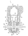
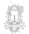
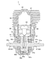
- FIG. 2 is a cross-sectional view of the two-cycle engine of the present embodiment as viewed from the AA direction of FIG. It is the figure which showed the 2-cycle engine of this embodiment, and is a sectional side view in an intake and compression stroke.
- FIG. 4 is a cross-sectional view of the two-cycle engine of the present embodiment as viewed from the BB direction in FIG. 3.
- FIG. 4 is a cross-sectional view of the two-cycle engine of the present embodiment as viewed from the CC direction of FIG. 3. It is the perspective view which showed the crankshaft in the 2-cycle engine of this embodiment.
- a two-cycle engine 1 according to this embodiment shown in FIG. 1 is used for a small work machine such as a brush cutter or a blower.
- the two-cycle engine 1 has a piston 50 that is slidably mounted in a cylinder 60, and allows a mixed gas of fuel and air filled in the crank chamber 10 to pass through two scavenging passages 20 and 30.
- the piston 50 is reciprocated in the cylinder 60 by an expansion force when the mixed gas is burned in the combustion chamber 40 formed in the upper portion of the cylinder 60 (see FIG. 2).
- various power mechanisms in the two-cycle engine 1 of the present embodiment have the same configuration as that of a known two-cycle engine, and thus detailed description thereof is omitted except for the characteristic configuration constituting the present invention.
- the two-cycle engine 1 includes a piston 50 slidably mounted in a cylinder 60, a suction passage 70 communicating with the crank chamber 10, and a combustion chamber 40 formed in the cylinder 60.
- the exhaust passage 80 communicated with, the first scavenging passage 20 and the second scavenging passage 30 (see FIG. 2) communicating the crank chamber 10 and the combustion chamber 40, and the reciprocating motion of the piston 50 in the crank chamber 10 A rotating crankshaft 90.
- the suction passage 70 is formed in a side portion of the cylinder block 61, one end is opened in the lower portion of the cylinder 60, and the other end is connected to a fuel supply passage (not shown).
- the opening on the cylinder 60 side of the suction passage 70 is blocked by the side surface of the piston 50 when the piston 50 is located at the bottom dead center in the cylinder 60.
- the opening on the cylinder 60 side of the suction passage 70 opens to the lower portion of the cylinder 60 and communicates with the crank chamber 10. .
- the exhaust passage 80 is formed on the side of the cylinder block 61 at a position opposite to the suction passage 70, with one end opening at the top of the cylinder 60 and the other end not shown. Connected to the exhaust pipe. As shown in FIG. 1, the opening on the cylinder 60 side of the exhaust passage 80 opens to the upper part of the cylinder 60 and communicates with the combustion chamber 40 when the piston 50 is located at the bottom dead center in the cylinder 60. Further, as shown in FIG. 3, the opening on the cylinder 60 side of the exhaust passage 80 is blocked by the side surface of the piston 50 when the piston 50 is located at the top dead center in the cylinder 60.
- the first scavenging passage 20 and the second scavenging passage 30 are formed in the cylinder block 61 at positions on the left and right sides of the cylinder 60 in FIG. That is, the first scavenging passage 20 and the second scavenging passage 30 are formed at positions shifted by 90 degrees in the circumferential direction of the cylinder 60 with respect to the suction passage 70 and the exhaust passage 80 as shown in FIG. . As shown in FIG. 2, one end of the first scavenging passage 20 and the second scavenging passage 30 opens at the top of the cylinder 60 at substantially the same height as the exhaust passage 80, and the other end opens into the crank chamber 10. .
- the openings of the first scavenging passage 20 and the second scavenging passage 30 on the cylinder 60 side are respectively opened on both sides of the opening of the exhaust passage 80 and sandwich the center portion of the cylinder 60. Are confronting each other.
- the opening part by the side of the cylinder 60 of the 1st scavenging passage 20 and the 2nd scavenging passage 30 is opened toward the wall surface on the opposite side to the wall surface by the side of the exhaust passage 80 in the cylinder 60.
- a partition part 21 is formed in the center part in the width direction.
- the partition 21 is a vertical wall that divides the opening into two at the center in the width direction, and extends in the cylinder 60 toward the wall on the side opposite to the wall on the exhaust passage 80 side.
- the opening on the cylinder 60 side of the first scavenging passage 20 and the second scavenging passage 30 opens above the cylinder 60 when the piston 50 is located at the bottom dead center in the cylinder 60.
- the opening on the cylinder 60 side of the first scavenging passage 20 and the second scavenging passage 30 is formed by the side surface of the piston 50 when the piston 50 is located at the top dead center in the cylinder 60 as shown in FIG. Blocked.
- the piston 50 is a member that reciprocates in the vertical direction in the cylinder 60, and has a circular cross-sectional shape in plan view.
- the suction passage 70 is closed by the side surface of the piston 50, and the exhaust passage 80 and the scavenging passages 20, 30 (see FIG. 2)
- the cylinder 50 is opened above the piston 50 and communicates with the combustion chamber 40.
- the exhaust passage 80 and the scavenging passages 20 and 30 are closed by the side surface of the piston 50, and the suction passage 70 is
- the cylinder 50 is opened below the piston 50 and communicates with the crank chamber 10.
- a concave communication groove 51 is formed in the circumferential direction of the piston 50 at the lower side on the second scavenging passage 30 side on the side surface of the piston 50.
- the communication groove 51 is configured such that the piston 50 is located at the top dead center in the cylinder 60, and the exhaust passage 80 and the second scavenging passage are closed by the side surfaces of the piston 50. 30 to communicate with each other (see FIG. 5).
- the crankshaft 90 has output shafts 91 a and 92 a that are rotatably supported by the crankcase 11, and the piston 50 is connected via a connecting rod 93, and the piston 50 reciprocates. In conjunction with the rotation in the crank chamber 10.
- a first crankshaft 91 disposed on the right side in FIG. 2 and a second crankshaft 92 disposed on the left side in FIG. 2 are assembled.
- an output shaft 91a extended toward the right side of FIG. 4 and a crank pin extended toward the left side of FIG. 4 at a position eccentric to the axis of the output shaft 91a.
- 91b and a counterweight 91c formed at a position symmetrical to the crank pin 91b across the output shaft 91a.
- the counterweight 91c of the first crankshaft 91 is a semicircular plate-like member protruding around the output shaft 91a.
- the tip corner portion on the first scavenging passage 20 side (the right side in FIG. 6) is chamfered to form a flat inclined surface 91d (see FIG. 4).
- the connecting portion 91e that connects the output shaft 91a and the crank pin 91b is chamfered at the tip corner on the first scavenging passage 20 side (right side in FIG. 6), and is flat.
- An inclined surface 91f is formed (see FIG. 4).
- an output shaft 92a extending toward the left side in FIG. 4, a through hole 92b formed at a position eccentric to the axis of the output shaft 92a, and the output shaft 91a are sandwiched.
- the second crankshaft 92 has a left-right contrast with the first crankshaft 91 except for the portion where the through hole 92b is formed.
- the tip corner portion on the second scavenging passage 30 side is chamfered, but the counterweight 91c of the first crankshaft 91 and the tip corner portion of the connecting portion 91e In comparison, since the tip corner is chamfered in a very small dimension, it is a substantially perpendicular corner.
- crank pin 91 b of the first crankshaft 91 is rotatably inserted in a through hole 93 a formed in the lower end portion of the connecting rod 93, and the tip portion thereof is the second crankshaft.
- 92 is fixed by being fitted into the through hole 92b.
- the connecting rod 93 has an upper end portion that is swingably connected to the piston 50, and a lower end portion that is connected to a crank pin 91 b of the crankshaft 90.
- the two-cycle engine 1 configured as described above operates as follows and exhibits the effects of the present invention.
- the crank chamber 10 In the intake / compression stroke, as shown in FIG. 3, when the piston 50 rises in the cylinder 60, the crank chamber 10 is in a negative pressure state, and is generated by a carburetor or a fuel injection device provided in a fuel supply passage (not shown). The mixed gas of fuel and air is filled into the crank chamber 10 through the suction passage 70.
- the exhaust passage 80 opens to the top of the cylinder 60 and communicates with the combustion chamber 40, and the combustion gas generated by the combustion of the mixed gas is exhausted. 80 is exhausted (exhaust stroke). Further, the gas mixture filled in the crank chamber 10 is compressed by the lowering of the piston 50.
- the first scavenging passage 20 and the second scavenging passage 30 are located above the cylinder 60 as shown in FIG. Open to the combustion chamber 40.
- the mixed gas compressed in the crank chamber 10 flows into the cylinder 60 through the first scavenging passage 20 and the second scavenging passage 30 (scavenging stroke).
- the staying combustion gas precedes the mixed gas in the second scavenging passage 30.
- the mixed gas flowing into the cylinder 60 from the first scavenging passage 20 flows into the opposite side of the exhaust passage 80 in the cylinder 60 from the mixed gas flowing into the cylinder 60 from the second scavenging passage 30. Since the gas is directed by the partition portion 21, the combustion gas and the mixed gas flowing into the cylinder 60 from the second scavenging passage 30 wrap around to the opposite side of the exhaust passage 80 in the cylinder 60.
- the corners on the first scavenging passage 20 side are chamfered to form inclined surfaces 91d and 91f.
- the mixed gas flowing into the first scavenging passage 20 from 10 flows more easily than the mixed gas flowing into the second scavenging passage 30 from the crank chamber 10. That is, the flow rate of the mixed gas flowing from the crank chamber 10 into the first scavenging passage 20 is larger than the flow rate of the mixed gas flowing from the crank chamber 10 into the second scavenging passage 30, and The flow rate of the mixed gas flowing into the 60 becomes higher than the flow rate of the mixed gas flowing into the cylinder 60 from the second scavenging passage 30.
- the mixed gas flowing into the cylinder 60 from the first scavenging passage 20 flows into the cylinder 60 more vigorously than the combustion gas flowing into the cylinder 60 from the second scavenging passage 30.
- the direction of the mixed gas flowing into the cylinder 60 from the passage 20 is reliably performed.
- the mixed gas flowing into the cylinder 60 from the first scavenging passage 20 is more in the cylinder 60 than the mixed gas flowing into the cylinder 60 from the second scavenging passage 30.
- the combustion gas flowing into the cylinder 60 from the second scavenging passage 30 is pushed out into the exhaust passage 80 by the mixed gas flowing into the cylinder 60 from the first scavenging passage 20. It is.
- the piston 50 that has reached the bottom dead center in the cylinder 60 is raised again in the cylinder 60 by the rotational force of the crankshaft 90, and the suction and compression strokes are repeated.
- the gas flowing into the cylinder 60 from the second scavenging passage 30 is exhausted to the exhaust passage 80. Since the combustion gas flows from the scavenging passage 30 into the cylinder 60 prior to the mixed gas, the amount of unburned mixed gas discharged into the exhaust passage 80 in the scavenging process is reduced. Further, the mixed gas flowing into the cylinder 60 from the first scavenging passage 20 passes through the opposite side of the exhaust passage 80 in the cylinder 60 from the gas flowing into the cylinder 60 from the second scavenging passage 30 and is exhausted. Reach passage 80.
- the mixed gas that has flowed into the cylinder 60 from the first scavenging passage 20 goes farther than the gas that has flowed into the cylinder 60 from the second scavenging passage 30 and reaches the exhaust passage 80, the final stage of the scavenging process , The amount of unburned mixed gas discharged into the exhaust passage 80 is reduced. Further, the mixed gas flowing into the cylinder 60 from the first scavenging passage 20 flows into the cylinder 60 on the opposite side of the exhaust passage 80 from the mixed gas flowing into the cylinder 60 from the second scavenging passage 30. Thus, the combustion gas that has flowed into the cylinder 60 from the second scavenging passage 30 is pushed out into the exhaust passage 80 by the mixed gas that has flowed into the cylinder 60 from the first scavenging passage 20. Exhausted.
- the amount of unburned mixed gas exhausted to the exhaust passage 80 is reduced, so that the unburned gas contained in the exhaust gas
- the combustion gas remaining in the combustion chamber 40 (in the cylinder 60) is reduced and the amount of mixed gas filling in the combustion chamber 40 is increased, so that the engine output can be increased. it can.
- the present invention has been described above. However, the present invention is not limited to the above-described embodiments, and various design changes can be made without departing from the spirit of the present invention.
- a mesh-shaped shielding plate 31 such as a punching metal sheet or a metal mesh at the opening of the second scavenging passage 30 on the cylinder 60 side, the first scavenging passage 20 to the cylinder 60.
- the mixed gas flowing in can be configured to flow more easily than the mixed gas flowing into the cylinder 60 from the second scavenging passage 30.
- the flow rate of the mixed gas flowing from the first scavenging passage 20 into the cylinder 60 is higher than the flow velocity of the mixed gas flowing from the second scavenging passage 30 into the cylinder 60.
- the mixed gas flowing into the cylinder 60 from the cylinder 20 can flow into the cylinder 60 more vigorously than the combustion gas flowing into the second scavenging passage 30 or the cylinder 60.
- the mixed gas flowing into the gas can be reliably directed.
- the shielding plate 31 is provided only at the opening on the cylinder 60 side of the second scavenging passage 30, but further on a part of the opening on the cylinder 60 side of the first scavenging passage 20. Also, a shielding plate may be provided.
- the mixed gas flowing from the crank chamber 10 into the first scavenging passage 20 is It can be configured to flow more easily than the mixed gas flowing into the second scavenging passage 30 from the crank chamber 10.
- the flow rate of the mixed gas flowing from the crank chamber 10 into the first scavenging passage 20 is larger than the flow rate of the mixed gas flowing from the crank chamber 10 into the second scavenging passage 30, and the first scavenging passage 20 From the second scavenging passage 30 into the cylinder 60 becomes higher than the flow velocity of the mixed gas flowing into the cylinder 60 from the second scavenging passage 30.
- the mixed gas flowing into the cylinder 60 from the first scavenging passage 20 can flow into the cylinder 60 more vigorously than the combustion gas flowing into the cylinder 60 from the second scavenging passage 30. It is possible to reliably direct the mixed gas flowing into the cylinder 60 from the scavenging passage 20.
- the mixed gas flowing into the cylinder 60 from the first scavenging passage 20 is allowed to flow into the cylinder 60 from the second scavenging passage 30. It can be configured to be easier to flow than the mixed gas flowing in. In this configuration, the flow velocity of the mixed gas flowing into the cylinder 60 from the first scavenging passage 20 is higher than the flow velocity of the mixed gas flowing into the cylinder 60 from the second scavenging passage 30. As a result, the mixed gas flowing into the cylinder 60 from the first scavenging passage 20 can flow into the cylinder 60 more vigorously than the combustion gas flowing into the cylinder 60 from the second scavenging passage 30.
- the protruding portion 32 is provided at the boundary between the crank chamber 10 and the second scavenging passage 30.
- the protruding portion 32 may be provided in the middle or upper portion of the second scavenging passage 30. The position is not limited.
- the partition part 21 is provided only in the first scavenging passage 20, but the partition part is also provided in the second scavenging passage 30 in addition to the first scavenging passage 20. May be provided.
- the partition part 21 formed in the opening part by the side of the cylinder 60 of the 1st scavenging passage 20 is comprised by the vertical wall,
- the 1st scavenging passage 20 The shape of the partition portion is not limited as long as the mixed gas flowing into the cylinder 60 can be reliably directed.
- the tip end corner portion on the first scavenging passage 20 side is chamfered and a flat inclined surface 91d, 91f is formed, but the mixed gas flowing from the crank chamber 10 into the first scavenging passage 20 is processed by processing the tip end corners of the counterweight 91c and the connecting portion 91e into a gentle arcuate inclined surface. It can also be configured to flow more easily than the mixed gas flowing into the second scavenging passage 30 from the crank chamber 10.
Landscapes
- Engineering & Computer Science (AREA)
- Chemical & Material Sciences (AREA)
- Combustion & Propulsion (AREA)
- Mechanical Engineering (AREA)
- General Engineering & Computer Science (AREA)
- Cylinder Crankcases Of Internal Combustion Engines (AREA)
Abstract
L'invention concerne un moteur à deux temps (1) comprenant un piston (50) qui est monté dans un cylindre (60), un passage d'échappement (80) qui conduit à une chambre de combustion (40) et un premier passage de balayage (20) ainsi qu'un second passage de balayage (30) qui permettent à un carter (10) et à la chambre de combustion (40) de communiquer l'un avec l'autre. Dans le piston (50), une rainure de communication (51) permet au passage d'échappement (80) et au second passage de balayage de communiquer l'un avec l'autre lorsque le passage d'échappement (80) et les passages de balayage (20, 30) respectifs sont fermés par le piston (50) et qu'une quantité de gaz mélangés provenant du premier passage de balayage (20), plus importante que la quantité de gaz mélangés provenant du second passage de balayage (30), s'écoule dans le côté opposé au passage d'échappement (80) dans la chambre de combustion (40). Selon cette conception, la quantité de gaz d'échappement non brûlés est fortement réduite, le gaz de combustion s'échappe en douceur de l'intérieur de la chambre de combustion (40), la chambre de combustion est remplie d'une quantité plus importante de gaz mélangés et, par conséquent, la puissance du moteur peut être augmentée.
Priority Applications (1)
| Application Number | Priority Date | Filing Date | Title |
|---|---|---|---|
| PCT/JP2008/050867 WO2009093310A1 (fr) | 2008-01-23 | 2008-01-23 | Moteur à deux temps |
Applications Claiming Priority (1)
| Application Number | Priority Date | Filing Date | Title |
|---|---|---|---|
| PCT/JP2008/050867 WO2009093310A1 (fr) | 2008-01-23 | 2008-01-23 | Moteur à deux temps |
Publications (1)
| Publication Number | Publication Date |
|---|---|
| WO2009093310A1 true WO2009093310A1 (fr) | 2009-07-30 |
Family
ID=40900828
Family Applications (1)
| Application Number | Title | Priority Date | Filing Date |
|---|---|---|---|
| PCT/JP2008/050867 Ceased WO2009093310A1 (fr) | 2008-01-23 | 2008-01-23 | Moteur à deux temps |
Country Status (1)
| Country | Link |
|---|---|
| WO (1) | WO2009093310A1 (fr) |
Cited By (2)
| Publication number | Priority date | Publication date | Assignee | Title |
|---|---|---|---|---|
| JP2010133370A (ja) * | 2008-12-08 | 2010-06-17 | Yamabiko Corp | 2サイクルエンジン |
| EP2415987B1 (fr) * | 2010-08-02 | 2018-12-12 | Yamabiko Corporation | Moteur à combustion interne à deux temps à récupération en boucle |
Citations (9)
| Publication number | Priority date | Publication date | Assignee | Title |
|---|---|---|---|---|
| JPS5194312U (fr) * | 1975-01-27 | 1976-07-29 | ||
| JPS59134323A (ja) * | 1983-01-19 | 1984-08-02 | Nippon Clean Engine Res | 時間差衝突層状掃気2サイクル機関 |
| JPH07279674A (ja) * | 1994-04-12 | 1995-10-27 | Daihatsu Motor Co Ltd | 二サイクル内燃機関における掃気装置 |
| JPH11287124A (ja) * | 1998-04-01 | 1999-10-19 | Maruyama Mfg Co Ltd | 2サイクルガソリンエンジン |
| JPH11315722A (ja) * | 1998-04-30 | 1999-11-16 | Tanaka Kogyo Kk | 2サイクルエンジン |
| JP2000186558A (ja) * | 1998-12-22 | 2000-07-04 | Mitsubishi Heavy Ind Ltd | 層状掃気2サイクルエンジン |
| JP2001027122A (ja) * | 1999-07-15 | 2001-01-30 | Maruyama Mfg Co Ltd | 2サイクルエンジン |
| JP2001323816A (ja) * | 2000-05-16 | 2001-11-22 | Kioritz Corp | 2サイクル内燃エンジン |
| JP2007077942A (ja) * | 2005-09-16 | 2007-03-29 | Shin Daiwa Kogyo Co Ltd | クランク室圧縮型2サイクルエンジン及び燃料粒子微細化装置 |
-
2008
- 2008-01-23 WO PCT/JP2008/050867 patent/WO2009093310A1/fr not_active Ceased
Patent Citations (9)
| Publication number | Priority date | Publication date | Assignee | Title |
|---|---|---|---|---|
| JPS5194312U (fr) * | 1975-01-27 | 1976-07-29 | ||
| JPS59134323A (ja) * | 1983-01-19 | 1984-08-02 | Nippon Clean Engine Res | 時間差衝突層状掃気2サイクル機関 |
| JPH07279674A (ja) * | 1994-04-12 | 1995-10-27 | Daihatsu Motor Co Ltd | 二サイクル内燃機関における掃気装置 |
| JPH11287124A (ja) * | 1998-04-01 | 1999-10-19 | Maruyama Mfg Co Ltd | 2サイクルガソリンエンジン |
| JPH11315722A (ja) * | 1998-04-30 | 1999-11-16 | Tanaka Kogyo Kk | 2サイクルエンジン |
| JP2000186558A (ja) * | 1998-12-22 | 2000-07-04 | Mitsubishi Heavy Ind Ltd | 層状掃気2サイクルエンジン |
| JP2001027122A (ja) * | 1999-07-15 | 2001-01-30 | Maruyama Mfg Co Ltd | 2サイクルエンジン |
| JP2001323816A (ja) * | 2000-05-16 | 2001-11-22 | Kioritz Corp | 2サイクル内燃エンジン |
| JP2007077942A (ja) * | 2005-09-16 | 2007-03-29 | Shin Daiwa Kogyo Co Ltd | クランク室圧縮型2サイクルエンジン及び燃料粒子微細化装置 |
Cited By (2)
| Publication number | Priority date | Publication date | Assignee | Title |
|---|---|---|---|---|
| JP2010133370A (ja) * | 2008-12-08 | 2010-06-17 | Yamabiko Corp | 2サイクルエンジン |
| EP2415987B1 (fr) * | 2010-08-02 | 2018-12-12 | Yamabiko Corporation | Moteur à combustion interne à deux temps à récupération en boucle |
Similar Documents
| Publication | Publication Date | Title |
|---|---|---|
| JP5922569B2 (ja) | 層状掃気2ストロークエンジン | |
| US6640755B2 (en) | Two-cycle internal combustion engine | |
| JP5370669B2 (ja) | 2サイクルエンジン | |
| CN102072009A (zh) | 空气先导式扫气的二冲程发动机 | |
| JP4585920B2 (ja) | 2サイクル内燃エンジン | |
| JP2011027017A (ja) | 2サイクルエンジン | |
| JP4606966B2 (ja) | 層状掃気2サイクル内燃エンジン | |
| CN102575580B (zh) | 两冲程发动机 | |
| WO2013118635A1 (fr) | Moteur à deux temps | |
| JP3773507B2 (ja) | 2サイクル内燃エンジン | |
| EP1069294B1 (fr) | Moteur à combustion interne à deux temps | |
| US8955475B2 (en) | Two-stroke internal combustion engine | |
| JP5060459B2 (ja) | 2サイクルエンジン | |
| US9719416B2 (en) | Stratified scavenging two-stroke engine | |
| JP6035197B2 (ja) | 層状掃気2ストロークエンジン | |
| JP2010043560A (ja) | 2サイクルエンジン | |
| JP2001329844A (ja) | 2サイクルエンジン | |
| JP7641846B2 (ja) | 2サイクルエンジン | |
| JP2012107552A (ja) | 層状掃気2ストロークエンジン | |
| JP4327041B2 (ja) | 4サイクルエンジン | |
| JP5594026B2 (ja) | 2サイクルエンジンおよびそれを備えたエンジン作業機 | |
| WO2012132658A1 (fr) | Moteur à deux temps | |
| JP2014114697A (ja) | 2ストロークエンジン | |
| JPS63314314A (ja) | 2サイクルエンジン | |
| CZ20013583A3 (cs) | Spalovací motor |
Legal Events
| Date | Code | Title | Description |
|---|---|---|---|
| 121 | Ep: the epo has been informed by wipo that ep was designated in this application |
Ref document number: 08703708 Country of ref document: EP Kind code of ref document: A1 |
|
| NENP | Non-entry into the national phase |
Ref country code: DE |
|
| NENP | Non-entry into the national phase |
Ref country code: JP |
|
| 122 | Ep: pct application non-entry in european phase |
Ref document number: 08703708 Country of ref document: EP Kind code of ref document: A1 |