WO2009093347A1 - ボイラ構造 - Google Patents
ボイラ構造 Download PDFInfo
- Publication number
- WO2009093347A1 WO2009093347A1 PCT/JP2008/061193 JP2008061193W WO2009093347A1 WO 2009093347 A1 WO2009093347 A1 WO 2009093347A1 JP 2008061193 W JP2008061193 W JP 2008061193W WO 2009093347 A1 WO2009093347 A1 WO 2009093347A1
- Authority
- WO
- WIPO (PCT)
- Prior art keywords
- air
- furnace
- burner
- flame
- boiler structure
- Prior art date
- Legal status (The legal status is an assumption and is not a legal conclusion. Google has not performed a legal analysis and makes no representation as to the accuracy of the status listed.)
- Ceased
Links
Images


Classifications
-
- F—MECHANICAL ENGINEERING; LIGHTING; HEATING; WEAPONS; BLASTING
- F23—COMBUSTION APPARATUS; COMBUSTION PROCESSES
- F23C—METHODS OR APPARATUS FOR COMBUSTION USING FLUID FUEL OR SOLID FUEL SUSPENDED IN A CARRIER GAS OR AIR
- F23C7/00—Combustion apparatus characterised by arrangements for air supply
- F23C7/02—Disposition of air supply not passing through burner
- F23C7/04—Disposition of air supply not passing through burner to obtain maximum heat transfer to wall of combustion chamber
-
- F—MECHANICAL ENGINEERING; LIGHTING; HEATING; WEAPONS; BLASTING
- F22—STEAM GENERATION
- F22B—METHODS OF STEAM GENERATION; STEAM BOILERS
- F22B21/00—Water-tube boilers of vertical or steeply-inclined type, i.e. the water-tube sets being arranged vertically or substantially vertically
-
- F—MECHANICAL ENGINEERING; LIGHTING; HEATING; WEAPONS; BLASTING
- F23—COMBUSTION APPARATUS; COMBUSTION PROCESSES
- F23C—METHODS OR APPARATUS FOR COMBUSTION USING FLUID FUEL OR SOLID FUEL SUSPENDED IN A CARRIER GAS OR AIR
- F23C5/00—Disposition of burners with respect to the combustion chamber or to one another; Mounting of burners in combustion apparatus
- F23C5/08—Disposition of burners
- F23C5/28—Disposition of burners to obtain flames in opposing directions, e.g. impacting flames
-
- F—MECHANICAL ENGINEERING; LIGHTING; HEATING; WEAPONS; BLASTING
- F23—COMBUSTION APPARATUS; COMBUSTION PROCESSES
- F23C—METHODS OR APPARATUS FOR COMBUSTION USING FLUID FUEL OR SOLID FUEL SUSPENDED IN A CARRIER GAS OR AIR
- F23C5/00—Disposition of burners with respect to the combustion chamber or to one another; Mounting of burners in combustion apparatus
- F23C5/08—Disposition of burners
- F23C5/32—Disposition of burners to obtain rotating flames, i.e. flames moving helically or spirally
-
- F—MECHANICAL ENGINEERING; LIGHTING; HEATING; WEAPONS; BLASTING
- F23—COMBUSTION APPARATUS; COMBUSTION PROCESSES
- F23C—METHODS OR APPARATUS FOR COMBUSTION USING FLUID FUEL OR SOLID FUEL SUSPENDED IN A CARRIER GAS OR AIR
- F23C6/00—Combustion apparatus characterised by the combination of two or more combustion chambers or combustion zones, e.g. for staged combustion
- F23C6/04—Combustion apparatus characterised by the combination of two or more combustion chambers or combustion zones, e.g. for staged combustion in series connection
- F23C6/045—Combustion apparatus characterised by the combination of two or more combustion chambers or combustion zones, e.g. for staged combustion in series connection with staged combustion in a single enclosure
-
- F—MECHANICAL ENGINEERING; LIGHTING; HEATING; WEAPONS; BLASTING
- F23—COMBUSTION APPARATUS; COMBUSTION PROCESSES
- F23L—SUPPLYING AIR OR NON-COMBUSTIBLE LIQUIDS OR GASES TO COMBUSTION APPARATUS IN GENERAL ; VALVES OR DAMPERS SPECIALLY ADAPTED FOR CONTROLLING AIR SUPPLY OR DRAUGHT IN COMBUSTION APPARATUS; INDUCING DRAUGHT IN COMBUSTION APPARATUS; TOPS FOR CHIMNEYS OR VENTILATING SHAFTS; TERMINALS FOR FLUES
- F23L9/00—Passages or apertures for delivering secondary air for completing combustion of fuel
Definitions
- the present invention relates to a boiler structure corresponding to various fuels containing coal and sulfur.
- a technology is known to increase the oxygen concentration with the air introduced toward the wall surface inside the furnace.
- a swirl flow is formed by installing burners at the four corners of the furnace with a rectangular cross section.
- there is one that forms an air flow that is offset from each burner to the furnace wall side see, for example, Patent Document 1).
- a nozzle that feeds curtain air or curtain exhaust gas that bends the course of the flame is provided to slag the periphery of the burner.
- Patent Document 1 cannot effectively increase the oxygen concentration because oxygen in the air is consumed before reaching the target wall surface.
- auxiliary power such as a compressor increases.
- Patent Document 2 it is necessary to introduce curtain air or curtain exhaust gas at a flow velocity high enough to bend the course of the flame, which is also not preferable because auxiliary power such as a compressor increases.
- the fuel and combustion air that are introduced into the furnace from the burners provided at multiple locations on the furnace wall that form a rectangular cross section correspond to various fuels containing coal and sulfur.
- a swirl combustion type boiler structure configured to form and burn, it is desired to efficiently suppress or prevent corrosion and slugging generated on the furnace wall in the furnace.
- the present invention has been made in view of the above circumstances, and an object of the present invention is to provide a boiler structure capable of efficiently suppressing or preventing corrosion and slagging occurring on a furnace wall in a furnace. It is in.
- the boiler structure according to the present invention is configured such that fuel and combustion air that are input from a burner provided at a plurality of locations on a furnace wall that forms a rectangular cross section into a furnace form a swirl and burn.
- an air charging part is provided in the vicinity of a flame affected part of a furnace wall surface where a flame formed for each burner approaches or contacts, and an air concentration part is formed to have a higher air concentration than the surroundings.
- the high air concentration region is preferably formed so as to cover the reduction combustion zone inside the furnace in the vertical direction, thereby also in the vertical direction in the furnace where corrosion and slugging are a concern.
- a region having a high air concentration can be formed by introducing air at a low flow rate.
- the air input portion introduces the low-pressure burner secondary air by bypass from an adjacent burner, thereby simplifying the structure while suppressing a significant change in structure and an increase in the number of components.
- the air input section is preferably provided around the deslagger nozzle, thereby forming a region with a high air concentration on the furnace wall surface that is prone to slagging and being thermally severe. It is possible to cool the periphery of the insertion portion of the deslagger nozzle.
- the present invention described above is effective in suppressing slagging in a coal-fired boiler, and is effective in improving corrosion resistance against hydrogen sulfide in a boiler corresponding to various fuels containing a sulfur content. Furthermore, if the low-pressure burner secondary air is bypassed and introduced from the adjacent burner as the air used in the air input section described above, significant changes in the boiler structure and increase in the number of components are minimized. To simplify the structure.
- FIG. 2A It is a figure which shows one Embodiment of the boiler structure which concerns on this invention, and is a horizontal sectional view which shows the reduction combustion zone of a furnace. It is a figure which shows one Embodiment of the boiler structure which concerns on this invention, and is a perspective view which shows an external appearance outline
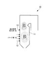
- a boiler 10 shown in FIG. 5 burns fuel by introducing multiple stages of combustion air into the furnace 11 in order to reduce NOx.
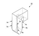
- the multistage charging is performed by the burner portion Ba in the furnace 11 where the plurality of burners 12 are provided, and the additional air charging portion Aa in the area where the additional air charging nozzle 13 is provided above the burner portion Ba.
- two-stage combustion air injection That is, in this boiler 10, about 70% of the required amount of combustion air is charged in the first burner portion Ba, and the remaining 30% is charged in the additional air charging portion Aa, so that the reduction combustion zone and complete combustion are performed.
- Two-stage combustion for NOx countermeasures consisting of zones is performed.
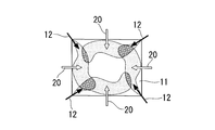
- the boiler 10 mentioned above is a revolving combustion type in which the furnace 11 has a rectangular cross section, as shown, for example in FIG. 1A.
- the fuel and the combustion air introduced into the furnace 11 from a plurality of burners 12 provided on the furnace wall 11 a form a swirl flame and burn in the furnace 11. It is configured.
- fuel and combustion air are input from the burners 12 provided at eight positions in a horizontal section, and two adjacent swirling flows are formed in the furnace 11. Yes.
- a region having a higher air concentration than the surroundings is formed in the vicinity of the flame affected part of the furnace wall surface (furnace wall 11a) with which the flame formed for each burner 12 approaches or comes into contact with such a boiler 10.
- An air input unit 20 is provided. Specifically, in the horizontal section of the eight-corner furnace shown in FIG. 1A, for example, one place at each appropriate place on each furnace wall 11a forming a rectangle, a total of four air inlets 20 are provided. Note that the formation of a region having a high air concentration means the formation of a region having a high oxygen concentration. Therefore, in such a region, the reducing atmosphere is an oxidizing atmosphere.
- a region having a higher air concentration than the periphery is formed along the substantially wall surface.
- a relatively high flow velocity for example, 40 m / sec or more
- the furnace wall surface in a region where corrosion or slagging is a concern
- the air input unit 20 bypasses the low-pressure burner secondary air from the adjacent burner 12 and introduces the air into the furnace 11 at a low flow rate, thereby forming a region with a high air concentration.
- Nozzle. The air input from the air input unit 20 forms a region with a high air concentration along the furnace wall 11a in the vicinity of the flame affected part in a plan view of the furnace 11, and further, in the vertical direction of the furnace 11.
- a plurality of stages of air injection portions 20 are also provided in the vertical direction.
- the reduction combustion zone is a region where a large amount of hydrogen sulfide, which is a corrosive component, is generated, and is also a region that becomes a reduction region with a high thermal load in the furnace 11, and therefore the wall surface 11a in this region has a severe corrosive environment.
- the air injection unit 20 is disposed around the furnace wall 11a where the flame approaches or comes into contact with the burner 12 so as to be substantially at the same height position. This is because the flame is formed so as to extend from the burner 12 in a substantially horizontal direction, and the flame-affected portion of the furnace wall 11a is substantially the same height as the installation position of the burner 12.
- the burner 12 in the reduction combustion zone is usually arranged in a plurality of stages above and below, a plurality of flame-affected portions of the furnace wall 11a are also formed at the top and bottom. Accordingly, the above-described air input unit 20 is also provided with a plurality of stages in the vertical direction according to the number of stages of the burner 12, in other words, according to the number of stages in the vertical direction where the flame is formed. That is, even in the vertical direction in the furnace 11 where corrosion and slugging are a concern, a region with a high air concentration can be formed by introducing air at a low flow rate.
- the low-flow-rate air introduced from the air introduction unit 20 disposed in the vicinity of the flame-affected part of the furnace wall 11a formed for each burner 12 has a higher air concentration than the surroundings.
- the region By forming the region, it functions as an air layer that blocks between the furnace wall 11a and the flame.
- the furnace wall 11a in the region that has been the flame-affected zone is reduced in the thermal influence received from the flame, etc., and can be reduced or prevented from corrosion and slugging by being in a partially oxidizing atmosphere.
- the air injection unit 20 described above may be input to the periphery from the vicinity of the flame-affected zone, it is possible to use low-flow-rate air that requires a small auxiliary power. That is, there is no need to supply high-pressure and high-velocity air using a compressor or the like that is operated with large power as in the case of supplying air aiming at a remote position, and in particular, low pressure from the burner 12 If the secondary air is introduced and used, in addition to reducing the supplementary power, it is possible to suppress a significant structural change and increase in the number of components, thereby simplifying the structure.
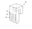
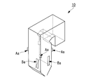
- the air inlet 20 described above is provided around the deslagger nozzle 31 by using a deslagger nozzle insertion portion 30 between the burner portion Ba and the additional air inlet Aa as shown in FIG. 1B, for example. It has been.
- the deslagger nozzle insertion portion 30 is a device for removing slag adhering to the furnace wall 11a.
- the furnace wall is formed by steam sprayed from a deslagger nozzle 31 inserted into the furnace 11. 11a is cleaned.
- the deslagger nozzle insertion portion 30 is installed in a position where the thermal load is high even in the furnace 11 due to the reducing atmosphere and the slag is likely to adhere, the above-described region where the air concentration is high due to the input of air is formed. Is effective.
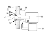
- FIG. 2A a deslagger nozzle 31 is inserted and attached to a nozzle hole 32 penetrating the furnace wall 11a in the deslagger nozzle insertion portion 30.
- the deslagger nozzle 31 is supplied with steam that is injected through the steam duct 33 when slag is removed.
- Reference numeral 34 in the drawing is a seal member provided between a nozzle body 21 and a deslagger nozzle 31 of an air inlet nozzle (air inlet portion) 20 described later.
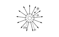
- the air injection nozzle 20 has a ring-shaped space formed between the deslagger nozzle 31 and the nozzle hole 32 as an air flow path 22, and a nozzle main body 21 having a disk-shaped flange 21 a at the end of the cylinder. It is attached in the furnace 11.
- the nozzle body 21 is fixed to the outer periphery of the deslagger nozzle 31 via a seal member 34, for example, and the flange portion 21a in the furnace 11 and the furnace wall 11a face each other substantially in parallel at a predetermined interval. Therefore, the air introduced into the furnace 11 from the nozzle body 21 flows out along the furnace wall 11a toward the entire circumference in the circumferential direction by colliding with the flange portion 21a.
- the air injection nozzle 20 includes a wind box 23 provided on the outer wall side of the furnace 11.
- the wind box 23 communicates with the nozzle body 21 in the furnace 11 through the air flow path 22 and supplies air supplied from the air supply source 24.
- the air supply source 24 preferably uses, for example, low-pressure secondary air introduced from the burner 12, but primary air or pressurized air may be used as necessary.
- Such an air injection nozzle 20 forms a high air concentration region on the furnace wall 11a of the furnace 11 in a region where slagging is likely to occur, and cools the periphery of the deslagger nozzle insertion portion 30 in a thermally severe situation. can do. Accordingly, since an air layer having a higher air concentration than the periphery is formed around the furnace wall 11a that is likely to cause slagging, the corrosion of the wall surface is prevented or reduced by the partial oxidizing atmosphere, and the life of the furnace wall is extended. be able to.
- the thermally strict seal member 34 and the like can be cooled by this air flow. Furthermore, in the vicinity of the furnace wall 11a where the air injection nozzle 20 is provided, the oxygen concentration increases due to the increase in the air concentration and an oxidizing atmosphere is formed. In such an oxidizing atmosphere, the melting temperature of the slag becomes high, so that slugging can be alleviated.
- the air charging unit 20 that forms a region having a higher air concentration than the surroundings is provided in the vicinity of the furnace wall 11a that becomes a flame-affected portion when a flame formed for each burner 12 approaches or contacts. Since it is provided, the vicinity of the flame affected part is partially changed from a reducing atmosphere to an oxidizing atmosphere due to an increase in oxygen concentration. As a result, corrosion and slagging can be suppressed or prevented to extend the wall life.
- Such a boiler structure is particularly effective in suppressing slagging in a coal-fired boiler, and is particularly effective in improving corrosion resistance in a boiler corresponding to various fuels containing sulfur.
- the optimum position of the horizontal cross-sectional position of the air input unit 20 differs depending on various conditions such as the shape of the furnace 11, the position and number of burners 12, and the formation of a swirling flame. That is, the region of the flame-affected zone where the flame formed for each burner 12 approaches or contacts the furnace wall 11a differs depending on the arrangement of the burners 12 and the swirling flow flame formed, for example, as shown in FIGS. 1A and 1B.
- the positional relationship between the burner 12 and the air charging unit 20 is different for each boiler structure.
- the furnace 11 is rectangular, and four burners 12 are arranged on two opposing long sides to form two left and right swirling flows.
- the burner 12 is inclined toward the approximate center position of each swirl flow, that is, toward the approximately center position of a square obtained by dividing the rectangle into two, so that the swirl flow that is nearly elliptical. Two are formed. Therefore, in this case, the flame-affected portion where the flame approaches or contacts is in the vicinity of the two corners and the central portion of the long side, and the air injection portions 20 are provided at four locations so as to cover these regions. .
- the furnace 11 is square, and four burners 12 offset from the center position of each side are arranged to form one swirl flow. ing. Since the burner 12 in this case is directed to the opposing wall surface, a swirl flow is formed by the offset of each burner 12. In such an arrangement of the burner 12, each flame flows toward the vicinity of the center of the wall surface on the downstream side due to the influence of the flame formed on the upstream side of the swirl flow. Accordingly, since the flame-affected zone in this case is in the vicinity of the center of each side, four air injection portions 20 are provided at the center of each side so as to cover these regions.
- the furnace 11 is made into a square, and the burner 12 is arrange
- air inlets 20 are provided at four locations in the center of each side so as to cover these regions.
- the optimal position of the air input unit 20 may be selected according to the arrangement of the burner 12 and the like.
- this invention is not limited to embodiment mentioned above, In the range which does not deviate from the summary of this invention, it can change suitably.
Landscapes
- Engineering & Computer Science (AREA)
- Mechanical Engineering (AREA)
- General Engineering & Computer Science (AREA)
- Chemical & Material Sciences (AREA)
- Combustion & Propulsion (AREA)
- Physics & Mathematics (AREA)
- Thermal Sciences (AREA)
- Combustion Of Fluid Fuel (AREA)
- Air Supply (AREA)
Abstract
Description
一方、この還元燃焼ゾーンでは、腐食成分である硫化水素が多量に発生するため、火炉壁面は厳しい腐食環境下にある。このため、炉壁への溶射や定期的な炉壁パネル交換等のメンテナンスが必要となっている。また、上述した還元燃焼ゾーンは、炉内でも熱負荷が高い還元雰囲気となる領域であるため、スラグの付着も懸念されている。
また、火炉壁の中央部に旋回火炎を発生させるバーナが設けられている微粉炭焚きボイラにおいては、火炎の進路を曲げるカーテンエアまたはカーテン排ガスを投入するノズルを設けて、バーナ周辺部のスラッギングを防止する技術が開示されている。(たとえば、特許文献2参照)
また、特許文献2の従来技術においても、火炎の進路を曲げる程度の高い流速でカーテンエアまたはカーテン排ガスを投入する必要があるため、やはり圧縮機等の補機動力が増加して好ましくない。
本発明は、上記の事情に鑑みてなされたものであり、その目的とするところは、火炉内の炉壁に発生する腐食やスラッギングを効率よく抑制または防止することができるボイラ構造を提供することにある。
本発明に係るボイラ構造は、矩形断面を形成する炉壁の複数箇所に設けたバーナから火炉内へ向けて投入される燃料及び燃焼用空気が旋回流を形成して燃焼するように構成された旋回燃焼型のボイラ構造において、前記バーナ毎に形成される火炎が接近または接触する火炉壁面の火炎影響部近傍に、周辺より空気濃度の高い領域を形成する空気投入部を設けたことを特徴とするものである。
さらに、上述した空気投入部で使用する空気として、近接するバーナから低圧のバーナ2次空気をバイパスさせて導入するようにすれば、ボイラ構造の大幅な変更や構成部品の増加を最小限に抑えて構造を簡素化できる。
11 火炉
11a 炉壁
12 バーナ
20 空気投入部(空気投入ノズル)
30 デスラッガノズル挿入部
図5に示すボイラ10は、低NOx化を図るため、火炉11内に燃焼用空気を多段投入して燃料を燃焼させるものである。この場合の多段投入は、火炉11において複数のバーナ12が設けられている領域のバーナ部Baと、このバーナ部Baより上部に追加空気投入ノズル13が設けられている領域の追加空気投入部Aaとにおいて、2段階の燃焼用空気投入を行うものである。すなわち、このボイラ10においては、最初のバーナ部Baで燃焼用空気必要量の70%程度が投入され、残る30%程度が追加空気投入部Aaで投入されることにより、還元燃焼ゾーン及び完全燃焼ゾーンよりなるNOx対策の2段燃焼が行われている。
なお、図1Aに示す8コーナー炉の構成例では、水平断面で8箇所に設けられたバーナ12から燃料及び燃焼用空気が投入され、火炉11内には隣接する二つの旋回流が形成されている。
なお、空気濃度の高い領域の形成は、酸素濃度の高い領域の形成を意味しているので、このような領域では還元雰囲気が酸化雰囲気となる。
この結果、還元燃焼ゾーンにおいて、バーナ12毎に形成される炉壁11aの火炎影響部周辺は、近傍に配設された空気投入部20から投入される低流速の空気が周辺より空気濃度の高い領域を形成することにより、炉壁11aと火炎との間を遮断する空気層として機能する。このため、火炎影響部となっていた領域の炉壁11aは、火炎から受ける熱影響等が低減されるとともに、部分的な酸化雰囲気になることで腐食やスラッギングの低減または防止が可能となる。
すなわち、デスラッガノズル挿入部30は、火炉11内でも還元雰囲気のため熱負荷が高く、スラグの付着が懸念される位置に設置されるため、上述した空気投入による空気濃度の高い領域を形成することが有効である。
図2Aにおいて、デスラッガノズル挿入部30には、デスラッガノズル31が炉壁11aを貫通するノズル孔32に挿入して取り付けられている。このデスラッガノズル31には、蒸気ダクト33を介してスラグ除去時に噴射する蒸気が供給される。なお、図中の符号34は、後述する空気投入ノズル(空気投入部)20のノズル本体21とデスラッガノズル31との間に設けられたシール部材である。
さらに、空気投入ノズル20が設けられた炉壁11aの近傍では、空気濃度が上昇することにより酸素濃度も上昇して酸化雰囲気となる。このような酸化雰囲気ではスラグの溶融温度が高くなるので、スラッギングの緩和が可能となる。
従って、この場合の火炎が接近または接触する火炎影響部は、2箇所の角部と長辺中央部付近となり、これらの領域をカバーするようにして空気投入部20が4箇所に設けられている。
従って、この場合の火炎影響部は各辺の中央部付近となるため、これらの領域をカバーするようにして、各辺中央部に空気投入部20が4箇所に設けられている。
このように、空気投入部20の設置位置については、バーナ12の配置等に応じて適宜最適位置を選択すればよい。
なお、本発明は上述した実施形態に限定されるものではなく、本発明の要旨を逸脱しない範囲内において適宜変更することができる。
Claims (4)
- 矩形断面を形成する炉壁の複数箇所に設けたバーナから火炉内へ向けて投入される燃料及び燃焼用空気が旋回流を形成して燃焼するように構成された旋回燃焼型のボイラ構造において、
前記バーナ毎に形成される火炎が接近または接触する火炉壁面の火炎影響部近傍に、周辺より空気濃度の高い領域を形成する空気投入部を設けたことを特徴とするボイラ構造。 - 前記空気濃度の高い領域が、上下方向に火炉内部の還元燃焼ゾーンをカバーして形成されることを特徴とする請求項1に記載のボイラ構造。
- 前記空気投入部が、近接するバーナから低圧のバーナ2次空気をバイパスさせて導入することを特徴とする請求項1または2に記載のボイラ構造。
- 前記空気投入部が、デスラッガノズルの周囲に設けられていることを特徴とする請求項1から3のいずれかに記載のボイラ構造。
Priority Applications (6)
| Application Number | Priority Date | Filing Date | Title |
|---|---|---|---|
| CN2008801252553A CN101925780B (zh) | 2008-01-23 | 2008-06-19 | 锅炉结构 |
| MX2010007776A MX2010007776A (es) | 2008-01-23 | 2008-06-19 | Estructura de hervidor. |
| EP08765748.2A EP2233833B1 (en) | 2008-01-23 | 2008-06-19 | Boiler structure |
| ES08765748T ES2706022T3 (es) | 2008-01-23 | 2008-06-19 | Estructura de caldera |
| US12/811,901 US20100279239A1 (en) | 2008-01-23 | 2008-06-19 | Boiler structure |
| BRPI0822013A BRPI0822013B1 (pt) | 2008-01-23 | 2008-06-19 | estrutura de caldeira de aquecimento circulante |
Applications Claiming Priority (2)
| Application Number | Priority Date | Filing Date | Title |
|---|---|---|---|
| JP2008-012503 | 2008-01-23 | ||
| JP2008012503A JP5022248B2 (ja) | 2008-01-23 | 2008-01-23 | ボイラ構造 |
Publications (1)
| Publication Number | Publication Date |
|---|---|
| WO2009093347A1 true WO2009093347A1 (ja) | 2009-07-30 |
Family
ID=40900863
Family Applications (1)
| Application Number | Title | Priority Date | Filing Date |
|---|---|---|---|
| PCT/JP2008/061193 Ceased WO2009093347A1 (ja) | 2008-01-23 | 2008-06-19 | ボイラ構造 |
Country Status (12)
| Country | Link |
|---|---|
| US (1) | US20100279239A1 (ja) |
| EP (1) | EP2233833B1 (ja) |
| JP (1) | JP5022248B2 (ja) |
| CN (1) | CN101925780B (ja) |
| BR (1) | BRPI0822013B1 (ja) |
| CL (1) | CL2008002173A1 (ja) |
| ES (1) | ES2706022T3 (ja) |
| MX (1) | MX2010007776A (ja) |
| MY (1) | MY152332A (ja) |
| RU (1) | RU2461773C2 (ja) |
| TW (1) | TWI434011B (ja) |
| WO (1) | WO2009093347A1 (ja) |
Families Citing this family (9)
| Publication number | Priority date | Publication date | Assignee | Title |
|---|---|---|---|---|
| JP5374404B2 (ja) | 2009-12-22 | 2013-12-25 | 三菱重工業株式会社 | 燃焼バーナおよびこの燃焼バーナを備えるボイラ |
| JP5530373B2 (ja) | 2011-01-12 | 2014-06-25 | バブコック日立株式会社 | ボイラ装置 |
| JP4955117B1 (ja) * | 2011-03-15 | 2012-06-20 | 新日鉄エンジニアリング株式会社 | 炉頂燃焼式熱風炉 |
| JP4892107B1 (ja) | 2011-03-23 | 2012-03-07 | 新日鉄エンジニアリング株式会社 | 炉頂燃焼式熱風炉 |
| CN102777880B (zh) * | 2012-07-19 | 2014-10-01 | 国网浙江省电力公司电力科学研究院 | 一种防止电站锅炉高温腐蚀的可调式热空气装置 |
| JP6109718B2 (ja) * | 2013-11-15 | 2017-04-05 | 三菱日立パワーシステムズ株式会社 | ボイラ |
| CN106871113A (zh) * | 2017-04-07 | 2017-06-20 | 贵州电网有限责任公司电力科学研究院 | 一种对冲切圆燃烧方式电站锅炉的燃烧器型式的选择方法 |
| CN106871112A (zh) * | 2017-04-07 | 2017-06-20 | 贵州电网有限责任公司电力科学研究院 | 一种冲切圆燃烧方式电站锅炉的燃烧器和磨煤机匹配方法 |
| CN112413635A (zh) * | 2020-11-17 | 2021-02-26 | 华能沁北发电有限责任公司 | 一种锅炉水冷壁高温腐蚀保护装置 |
Citations (12)
| Publication number | Priority date | Publication date | Assignee | Title |
|---|---|---|---|---|
| JPS62131106A (ja) * | 1985-12-04 | 1987-06-13 | Mitsubishi Heavy Ind Ltd | 蒸気発生装置の燃焼方法 |
| JPH03160202A (ja) * | 1989-11-20 | 1991-07-10 | Mitsubishi Heavy Ind Ltd | ボイラ |
| JPH04143503A (ja) * | 1990-10-05 | 1992-05-18 | Babcock Hitachi Kk | ボイラ装置及びその運転方法 |
| JPH05215305A (ja) * | 1992-01-31 | 1993-08-24 | Mitsubishi Heavy Ind Ltd | 微粉固体燃料燃焼装置 |
| JPH0642710A (ja) * | 1992-03-13 | 1994-02-18 | Babcock & Wilcox Co:The | 低NOx バーナーシステム |
| JPH07119923A (ja) | 1993-10-26 | 1995-05-12 | Mitsubishi Heavy Ind Ltd | 微粉炭焚きボイラの燃焼装置 |
| JPH0921506A (ja) * | 1995-07-05 | 1997-01-21 | Babcock Hitachi Kk | 微粉炭燃焼装置および微粉炭燃焼方法 |
| JPH11237003A (ja) * | 1998-02-19 | 1999-08-31 | Ishikawajima Harima Heavy Ind Co Ltd | 火炉の腐食防止装置 |
| JP2001012703A (ja) * | 1999-06-30 | 2001-01-19 | Babcock Hitachi Kk | バーナと該バーナを備えた燃焼装置 |
| US6237513B1 (en) | 1998-12-21 | 2001-05-29 | ABB ALSTROM POWER Inc. | Fuel and air compartment arrangement NOx tangential firing system |
| JP2002323215A (ja) * | 2001-04-26 | 2002-11-08 | Ishikawajima Harima Heavy Ind Co Ltd | ボイラ灰除去装置 |
| JP2005030675A (ja) * | 2003-07-11 | 2005-02-03 | Ishikawajima Harima Heavy Ind Co Ltd | ボイラ火炉のバウンダリー空気供給装置 |
Family Cites Families (12)
| Publication number | Priority date | Publication date | Assignee | Title |
|---|---|---|---|---|
| FI79403C (fi) * | 1984-06-01 | 1989-12-11 | Ahlstroem Oy | Foerbraenningsmetod. |
| SU1437613A1 (ru) * | 1986-07-09 | 1988-11-15 | Красноярский Политехнический Институт | Топка |
| RU2032125C1 (ru) * | 1989-04-06 | 1995-03-27 | Калинин Дмитрий Сергеевич | Предтопок |
| RU2032853C1 (ru) * | 1992-09-01 | 1995-04-10 | Сибирский филиал Всероссийского теплотехнического научно-исследовательского института | Призматическая экранированная топка |
| AU708109B2 (en) * | 1996-08-22 | 1999-07-29 | Babcock-Hitachi Kabushiki Kaisha | Combustion burner and combustion apparatus provided with said burner |
| JP3344694B2 (ja) * | 1997-07-24 | 2002-11-11 | 株式会社日立製作所 | 微粉炭燃焼バーナ |
| DE19749431C1 (de) * | 1997-11-08 | 1999-03-18 | Steinmueller Gmbh L & C | Verfahren zum Verbrennen von Brennstoffstaub in einer Tangentialfeuerung und Tangentialfeuerung zur Durchführung des Verfahrens |
| US7175423B1 (en) * | 2000-10-26 | 2007-02-13 | Bloom Engineering Company, Inc. | Air staged low-NOx burner |
| US7484956B2 (en) * | 2003-09-16 | 2009-02-03 | Praxair Technology, Inc. | Low NOx combustion using cogenerated oxygen and nitrogen streams |
| JP4150968B2 (ja) * | 2003-11-10 | 2008-09-17 | 株式会社日立製作所 | 固体燃料バーナと固体燃料バーナの燃焼方法 |
| JP4309853B2 (ja) * | 2005-01-05 | 2009-08-05 | バブコック日立株式会社 | 固体燃料バーナおよび燃焼方法 |
| RU2303203C1 (ru) * | 2006-06-29 | 2007-07-20 | Закрытое акционерное общество Акционерная фирма "Перспектива" Опытно-механический завод | Газогенератор с водяным котлом |
-
2008
- 2008-01-23 JP JP2008012503A patent/JP5022248B2/ja not_active Expired - Fee Related
- 2008-06-19 CN CN2008801252553A patent/CN101925780B/zh not_active Expired - Fee Related
- 2008-06-19 MY MYPI20103140 patent/MY152332A/en unknown
- 2008-06-19 RU RU2010129771/06A patent/RU2461773C2/ru active
- 2008-06-19 MX MX2010007776A patent/MX2010007776A/es active IP Right Grant
- 2008-06-19 US US12/811,901 patent/US20100279239A1/en not_active Abandoned
- 2008-06-19 ES ES08765748T patent/ES2706022T3/es active Active
- 2008-06-19 EP EP08765748.2A patent/EP2233833B1/en not_active Not-in-force
- 2008-06-19 WO PCT/JP2008/061193 patent/WO2009093347A1/ja not_active Ceased
- 2008-06-19 BR BRPI0822013A patent/BRPI0822013B1/pt not_active IP Right Cessation
- 2008-06-30 TW TW097124616A patent/TWI434011B/zh not_active IP Right Cessation
- 2008-07-24 CL CL2008002173A patent/CL2008002173A1/es unknown
Patent Citations (12)
| Publication number | Priority date | Publication date | Assignee | Title |
|---|---|---|---|---|
| JPS62131106A (ja) * | 1985-12-04 | 1987-06-13 | Mitsubishi Heavy Ind Ltd | 蒸気発生装置の燃焼方法 |
| JPH03160202A (ja) * | 1989-11-20 | 1991-07-10 | Mitsubishi Heavy Ind Ltd | ボイラ |
| JPH04143503A (ja) * | 1990-10-05 | 1992-05-18 | Babcock Hitachi Kk | ボイラ装置及びその運転方法 |
| JPH05215305A (ja) * | 1992-01-31 | 1993-08-24 | Mitsubishi Heavy Ind Ltd | 微粉固体燃料燃焼装置 |
| JPH0642710A (ja) * | 1992-03-13 | 1994-02-18 | Babcock & Wilcox Co:The | 低NOx バーナーシステム |
| JPH07119923A (ja) | 1993-10-26 | 1995-05-12 | Mitsubishi Heavy Ind Ltd | 微粉炭焚きボイラの燃焼装置 |
| JPH0921506A (ja) * | 1995-07-05 | 1997-01-21 | Babcock Hitachi Kk | 微粉炭燃焼装置および微粉炭燃焼方法 |
| JPH11237003A (ja) * | 1998-02-19 | 1999-08-31 | Ishikawajima Harima Heavy Ind Co Ltd | 火炉の腐食防止装置 |
| US6237513B1 (en) | 1998-12-21 | 2001-05-29 | ABB ALSTROM POWER Inc. | Fuel and air compartment arrangement NOx tangential firing system |
| JP2001012703A (ja) * | 1999-06-30 | 2001-01-19 | Babcock Hitachi Kk | バーナと該バーナを備えた燃焼装置 |
| JP2002323215A (ja) * | 2001-04-26 | 2002-11-08 | Ishikawajima Harima Heavy Ind Co Ltd | ボイラ灰除去装置 |
| JP2005030675A (ja) * | 2003-07-11 | 2005-02-03 | Ishikawajima Harima Heavy Ind Co Ltd | ボイラ火炉のバウンダリー空気供給装置 |
Also Published As
| Publication number | Publication date |
|---|---|
| US20100279239A1 (en) | 2010-11-04 |
| EP2233833A4 (en) | 2016-04-13 |
| MY152332A (en) | 2014-09-15 |
| EP2233833B1 (en) | 2018-10-24 |
| BRPI0822013A2 (pt) | 2015-07-21 |
| MX2010007776A (es) | 2010-08-09 |
| CN101925780A (zh) | 2010-12-22 |
| JP2009174751A (ja) | 2009-08-06 |
| TWI434011B (zh) | 2014-04-11 |
| CL2008002173A1 (es) | 2009-11-13 |
| JP5022248B2 (ja) | 2012-09-12 |
| EP2233833A1 (en) | 2010-09-29 |
| CN101925780B (zh) | 2013-01-09 |
| RU2461773C2 (ru) | 2012-09-20 |
| TW200933091A (en) | 2009-08-01 |
| RU2010129771A (ru) | 2012-02-27 |
| ES2706022T3 (es) | 2019-03-27 |
| BRPI0822013B1 (pt) | 2020-02-04 |
Similar Documents
| Publication | Publication Date | Title |
|---|---|---|
| JP5022248B2 (ja) | ボイラ構造 | |
| US9447969B2 (en) | Low NOx combustion process and burner therefor | |
| JP5931415B2 (ja) | 微粉炭バーナ | |
| JP7202467B2 (ja) | セメントキルン排ガスの脱硝方法 | |
| EP2781834B1 (en) | Oil-fired burner, solid fuel-fired burner unit and solid fuel-fired boiler | |
| CN104344399A (zh) | 贴壁风喷口以及锅炉、锅炉系统 | |
| JP2010271001A (ja) | 石炭焚ボイラ | |
| CN101960219B (zh) | 氧燃烧锅炉的煤粉燃烧器 | |
| JP2015102266A (ja) | ガスタービン燃焼器 | |
| JP2010139182A (ja) | 旋回燃焼ボイラ | |
| JP6246709B2 (ja) | 燃焼バーナ及びボイラ | |
| CN203478216U (zh) | 贴壁风喷口以及锅炉、锅炉系统 | |
| JP4664180B2 (ja) | ボイラ設備 | |
| JP5800423B2 (ja) | バーナおよびこれを備えたボイラ | |
| FI128749B (en) | Air arrangement above the fire and bubbling fluidized bed furnace | |
| JP2002349846A (ja) | 石炭焚きボイラおよび石炭焚きボイラのスラッギング防止方法 | |
| FI125911B (en) | Low Nitrogen Oxide Gas Burner and Method for Combustion of Fuel Gas | |
| JP6326593B2 (ja) | バーナ装置、およびそれを用いたボイラ、バーナ装置の燃焼方法 | |
| CN202532467U (zh) | 一种微油量点火装置的布置方式 | |
| JP2009162405A (ja) | ボイラの腐食低減構造 | |
| US20200386403A1 (en) | Fluid injection element for a furnace or a burner of a furnace and method for operating a furnace | |
| JPH0250008A (ja) | 微粉炭バーナ | |
| TH43937B (th) | โครงสร้างของหม้อน้ำ | |
| YU20050486A (sh) | Modifikovani kombinovani gorionik peći ba 2201 | |
| TH98436A (th) | โครงสร้างของหม้อน้ำ |
Legal Events
| Date | Code | Title | Description |
|---|---|---|---|
| WWE | Wipo information: entry into national phase |
Ref document number: 200880125255.3 Country of ref document: CN |
|
| 121 | Ep: the epo has been informed by wipo that ep was designated in this application |
Ref document number: 08765748 Country of ref document: EP Kind code of ref document: A1 |
|
| WWE | Wipo information: entry into national phase |
Ref document number: 2008765748 Country of ref document: EP |
|
| WWE | Wipo information: entry into national phase |
Ref document number: 12811901 Country of ref document: US Ref document number: 4211/CHENP/2010 Country of ref document: IN |
|
| WWE | Wipo information: entry into national phase |
Ref document number: MX/A/2010/007776 Country of ref document: MX Ref document number: 12010501606 Country of ref document: PH |
|
| NENP | Non-entry into the national phase |
Ref country code: DE |
|
| WWE | Wipo information: entry into national phase |
Ref document number: PI 2010003140 Country of ref document: MY |
|
| WWE | Wipo information: entry into national phase |
Ref document number: 2010129771 Country of ref document: RU |
|
| ENP | Entry into the national phase |
Ref document number: PI0822013 Country of ref document: BR Kind code of ref document: A2 Effective date: 20100716 |