WO2009093551A1 - モータ駆動制御装置 - Google Patents
モータ駆動制御装置 Download PDFInfo
- Publication number
- WO2009093551A1 WO2009093551A1 PCT/JP2009/050705 JP2009050705W WO2009093551A1 WO 2009093551 A1 WO2009093551 A1 WO 2009093551A1 JP 2009050705 W JP2009050705 W JP 2009050705W WO 2009093551 A1 WO2009093551 A1 WO 2009093551A1
- Authority
- WO
- WIPO (PCT)
- Prior art keywords
- motor
- position detection
- control device
- rotor
- drive
- Prior art date
- Legal status (The legal status is an assumption and is not a legal conclusion. Google has not performed a legal analysis and makes no representation as to the accuracy of the status listed.)
- Ceased
Links
Images



Classifications
-
- H—ELECTRICITY
- H02—GENERATION; CONVERSION OR DISTRIBUTION OF ELECTRIC POWER
- H02P—CONTROL OR REGULATION OF ELECTRIC MOTORS, ELECTRIC GENERATORS OR DYNAMO-ELECTRIC CONVERTERS; CONTROLLING TRANSFORMERS, REACTORS OR CHOKE COILS
- H02P6/00—Arrangements for controlling synchronous motors or other dynamo-electric motors using electronic commutation dependent on the rotor position; Electronic commutators therefor
- H02P6/14—Electronic commutators
- H02P6/16—Circuit arrangements for detecting position
-
- H—ELECTRICITY
- H02—GENERATION; CONVERSION OR DISTRIBUTION OF ELECTRIC POWER
- H02P—CONTROL OR REGULATION OF ELECTRIC MOTORS, ELECTRIC GENERATORS OR DYNAMO-ELECTRIC CONVERTERS; CONTROLLING TRANSFORMERS, REACTORS OR CHOKE COILS
- H02P6/00—Arrangements for controlling synchronous motors or other dynamo-electric motors using electronic commutation dependent on the rotor position; Electronic commutators therefor
- H02P6/12—Monitoring commutation; Providing indication of commutation failure
Definitions
- the present invention relates to a motor drive control device, and more particularly to a motor drive control device that controls the drive of a brushless DC motor based on a signal from a position detection unit that detects the position of a rotor.
- a three-phase brushless DC motor is used as a power source of these devices.
- a three-phase brushless DC motor has a rotor (hereinafter referred to as a rotor) made of a permanent magnet having a plurality of magnetic poles, and a stator (hereinafter referred to as a stator) having a three-phase drive coil. ing.
- a drive voltage corresponding to the position of the rotor with respect to the stator is applied to the drive coil of such a brushless DC motor by a motor drive control device for driving and controlling the motor.
- a current corresponding to the drive voltage flows through the drive coil, a magnetic field is generated, and the rotor rotates.
- a method for detecting the position of the rotor with respect to the stator a method using three rotor position detection sensors arranged so as to correspond to the respective three-phase drive coils is often used.
- This rotor position detection sensor is for detecting the relative position of the rotor with respect to the stator based on the magnetic field generated by the permanent magnet of the rotor, and specifically includes a Hall element, a Hall IC, and the like.
- the position detection sensor in which the malfunction has occurred cannot normally detect the position of the rotor.
- the motor drive control device applies a drive voltage to the motor such that a half cycle of one cycle has a normal waveform but the remaining half cycle has a waveform out of phase.
- the current supplied to the motor increases, the noise and vibration of the motor increase, and the rotation of the motor may become unstable.
- Patent Document 1 Japanese Patent Laid-Open No. 8-331886
- Patent Document 2 Japanese Patent Laid-Open No. 2000-184774
- motor drive control for detecting whether or not a defect has occurred in the position detection sensor.
- the device is known.
- the motor drive control device of Patent Literature 1 or Patent Literature 2 detects that the position detection sensor has a problem, it stops driving the motor.
- an object of the present invention is to provide a motor drive control device that can rotate a motor even when a problem occurs in a position detection sensor in a brushless DC motor.
- a motor drive control device includes a stator having a drive coil, a rotor having a plurality of magnetic poles, and a plurality of position detection units that output position detection signals indicating the position of the rotor with respect to the stator.
- a motor drive control device that controls the drive of a brushless DC motor, and includes an abnormality detection unit and a drive voltage generation unit.
- the abnormality detection unit detects an abnormality of each position detection signal.
- the drive voltage generation unit performs brushless DC based on at least one of the remaining position detection signals excluding the position detection signal detected as abnormal.
- a drive voltage for driving the motor is generated and output to the brushless DC motor.
- the brushless DC motor since a failure such as a failure has occurred in at least one position detection unit, and there is an abnormality in the position detection signal output from the position detection unit, the brushless DC motor has no abnormality remaining. A drive voltage generated based on at least one of the position detection signals is output. As described above, since the drive voltage is generated without using the abnormal position detection signal, the brushless DC motor can rotate stably without being affected by the abnormal position detection signal.
- a motor drive control device is the motor drive control device according to the first aspect, wherein the drive voltage generation unit uses at least one of the remaining position detection signals excluding the position detection signal detected as abnormal. To estimate the rotor position.
- the drive voltage generation unit generates a drive voltage based on the estimated rotor position.
- the drive voltage is generated based on the estimated rotor position instead of generating the drive voltage using the abnormal position detection signal. Thereby, the brushless DC motor can rotate more stably.
- a motor drive control device is the motor drive control device according to the first aspect, wherein the drive voltage generation unit is based on at least one of the remaining position detection signals excluding the position detection signal detected as abnormal. Then, a drive voltage pattern to be output to the brushless DC motor is selected from preset drive voltage patterns and output to the brushless DC motor.
- the position detection signal is a signal having a value of “1” or “0” and there is one position detection signal that is not used because it is abnormal is taken as an example.
- the energization width of the drive voltage output to the brushless DC motor is not uniform 120 degrees, and is 60 degrees, 120 degrees, and 180 degrees depending on the phase, and the drive voltage value varies depending on the phase, but for each phase
- the drive voltage output to the brushless DC motor is balanced between positive and negative, the brushless DC motor can operate stably.
- a motor drive control device is the motor drive control device according to any of the first to third aspects of the present invention, further comprising a rotation speed detection unit.
- the rotation speed detection unit detects the rotation speed of the rotor using at least one of the remaining position detection signals excluding the position detection signal detected as abnormal.
- a drive voltage generation part produces
- the rotational speed is detected using a position detection signal that is not abnormal, and the drive voltage is generated based on the rotational speed, so that the rotational speed control of the brushless DC motor is performed more appropriately. become.
- a motor drive control device is the motor drive control device according to any of the first through fourth aspects, wherein the position detection unit is one of a hall element and a hall IC.
- the position detection unit is one of a hall element and a hall IC.
- a motor drive control device is the motor drive control device according to any of the first to fifth aspects of the present invention, further comprising a phase difference detection unit.
- the phase difference detection unit detects a phase difference between the remaining position detection signals excluding the position detection signal detected as abnormal and an induced voltage generated in each of the drive coils corresponding to the remaining position detection signals.
- the drive voltage generation unit generates a drive voltage based on the phase difference and the polarity of the remaining position detection signals. According to this motor drive control device, for example, even if a problem occurs in a position detection unit whose specification is unknown, the brushless DC motor can rotate without being affected by an abnormal position detection signal.
- a motor drive control device is the motor drive control device according to any of the first to fifth aspects, further comprising a sensorless position estimating unit.
- the sensorless position estimation unit estimates the position of the rotor without using the position detection signal when all the position detection signals are detected as abnormal.
- the drive voltage generation unit generates a drive voltage using the estimated rotor position without using the position detection signal.
- the brushless DC motor can rotate without being affected by the position detection signal output from the position detection unit in which a problem has occurred even if a problem occurs in all the position detection units. Can continue.
- a motor drive control device is the motor drive control device according to any one of the first to sixth aspects, wherein the drive voltage generation unit is configured to apply a drive voltage energization period based on a normal / abnormal state of the position detection signal. To decide. The drive voltage generation unit outputs a drive voltage during the energization period. If at least one of the position detection units is abnormal, the brushless DC motor after activation may be affected by a position detection signal output from the abnormal position detection unit. As a result, an increase in the current applied to the brushless DC motor, noise, vibration, and the like occur.
- this motor drive control device outputs a drive voltage during the energization period determined based on the normal / abnormal state of the position detection signal, and stops outputting the drive voltage during other periods than the energization period.
- the brushless DC motor is not affected by the position detection signal that is abnormal after startup.
- the motor drive control device is the motor drive control device according to the eighth aspect of the present invention, wherein the energization period is a period in which the position detection signal is normal. As a result, the drive voltage is output to the brushless DC motor during a period in which the position detection signal is normal.
- a motor drive control device pertaining to a tenth aspect of the present invention is the motor drive control device pertaining to any of the first to ninth aspects of the present invention, further comprising a position determining unit.
- the position determining unit determines a predetermined position of the rotor that generates a torque in the forward rotation direction when a drive voltage is applied when the brushless DC motor is activated.
- the drive voltage generator generates a drive voltage that moves the rotor to a predetermined position, and generates a drive voltage for starting the brushless DC motor after the rotor has moved to the predetermined position. If it is known in advance that the position detection unit has failed before the brushless DC motor is started, the motor drive control device moves the brushless DC motor to a predetermined position by DC excitation, for example.
- the motor drive control device is the motor drive control device according to any one of the first to tenth aspects of the present invention, wherein the abnormality detection unit detects an abnormality of the position detection signal before starting the brushless DC motor.
- the brushless DC motor is not affected by an abnormal position detection signal immediately after starting.
- a motor drive control device is the motor drive control device according to any of the first to eleventh aspects of the present invention, further comprising a display unit.
- the display unit can display that the abnormality detection unit has detected an abnormality in the position detection signal. Thereby, the user can know that a defect has occurred in the position detection unit.
- a motor drive control device is the motor drive control device according to any of the first to twelfth aspects of the present invention, further comprising an instruction receiving unit.
- the instruction receiving unit can receive an execution instruction for an operation for generating a drive voltage based on at least one of the remaining position detection signals excluding the position detection signal detected as abnormal.
- the instruction receiving unit can receive an operation execution instruction for generating a drive voltage from a user via, for example, a remote controller.
- the motor drive control device can generate a drive voltage based on at least one of the remaining position detection signals excluding the abnormal position detection signal. Therefore, even when at least one of the position detection signals is abnormal, the motor drive control device can drive the brushless DC motor by performing the drive voltage generation operation based on a user instruction.
- a motor drive control device includes a stator having a drive coil, a rotor having a plurality of magnetic poles, and a plurality of position detection units that output position detection signals indicating the position of the rotor with respect to the stator.
- a motor drive control device that controls the drive of a brushless DC motor, and includes a position determination unit, a fixed voltage generation unit, and a drive voltage generation unit. When at least one of the position detection units is abnormal, the position determination unit determines a predetermined position of the rotor that generates a torque in the positive rotation direction when a drive voltage for starting the brushless DC motor is applied.
- the fixed voltage generation unit generates a fixed voltage such that the rotor is fixed at a predetermined position and outputs the fixed voltage to the brushless DC motor.
- the drive voltage generator generates a drive voltage after the rotor is fixed at a predetermined position, and outputs the drive voltage to the brushless DC motor. If it is known in advance that the position detection unit is out of order before starting the brushless DC motor, the motor drive voltage generation device, for example, after moving the brushless DC motor to a predetermined position and fixing it by direct current excitation. Start the motor. As a result, immediately after the brushless DC motor is started, torque in the forward rotation direction is generated in the brushless DC motor, and then the brushless DC motor is started using inertia, so that the brushless DC motor can be started reliably. .
- a motor drive control device is the motor drive control device according to the fourteenth aspect of the present invention, wherein the drive voltage generator determines a drive voltage energization period based on a normal / abnormal state of the position detection signal, and The drive voltage is output during the period. If at least one of the position detection units is abnormal, the brushless DC motor after activation may be affected by a position detection signal output from the abnormal position detection unit. As a result, an increase in the current applied to the brushless DC motor, noise, vibration, and the like occur.
- this motor drive control device outputs a drive voltage during the energization period determined based on the normal / abnormal state of the position detection signal, and stops outputting the drive voltage during other periods than the energization period.
- the brushless DC motor is not affected by the position detection signal that is abnormal after startup.
- the motor drive control device is the motor drive control device according to the fifteenth aspect of the present invention, wherein the energization period is a period in which the position detection signal is normal. As a result, the drive voltage is output to the brushless DC motor during a period in which the position detection signal is normal.
- a motor drive control device is the motor drive control device according to any of the fourteenth to sixteenth aspects of the present invention, further comprising an abnormality detection unit.
- the abnormality detection unit detects the abnormality of the position detection unit before starting the brushless DC motor.
- the brushless DC motor can rotate without being affected by an abnormal position detection signal immediately after startup.
- a motor drive control device is the motor drive control device according to the seventeenth aspect of the present invention, further comprising a display unit.
- the display unit can display that the abnormality detection unit has detected an abnormality in the position detection unit. Thereby, the user can know that a defect has occurred in the position detection unit.
- a motor drive control device is the motor drive control device according to any of the fourteenth to eighteenth aspects of the present invention, further comprising an instruction receiving unit.
- the instruction receiving unit can receive an instruction to execute a predetermined position of the rotor by the position determination unit, a fixed voltage generation operation by the fixed voltage generation unit, and a drive voltage generation operation by the drive voltage generation unit.
- the instruction receiving unit receives a determination operation of a predetermined position of the rotor by the position determination unit, a generation operation of the fixed voltage by the fixed voltage generation unit, and an execution instruction of the operation by the drive voltage generation unit, for example, It can be received from the user via the controller.
- the motor drive control device When receiving the execution instruction, the motor drive control device first moves and fixes the brushless DC motor to a predetermined position by DC excitation, for example, and then starts the brushless DC motor. Therefore, even when at least one of the position detection units is abnormal, the motor drive control device can start the brushless DC motor by performing the above operation based on the user's instruction.
- a motor drive control device includes a stator having a drive coil, a rotor having a plurality of magnetic poles, and a plurality of position detection units that output position detection signals indicating the position of the rotor with respect to the stator.
- a motor drive control device that controls the drive of a brushless DC motor, and includes a drive voltage generation unit and a sensorless position estimation unit.
- the driving voltage generation unit can generate a driving voltage for driving the brushless DC motor and output the driving voltage to the brushless DC motor.
- the sensorless position estimation unit estimates the position of the rotor without using the position detection signal. Then, when all the position detection units are normal, the drive voltage generation unit generates a drive voltage based on the position detection signal.
- the drive voltage generation unit generates a drive voltage for starting the brushless DC motor regardless of the position of the rotor, when at least one of the position detection units is abnormal before the start of the brushless DC motor. After starting the DC motor, a drive voltage is generated based on the estimated rotor position. Thereby, the brushless DC motor can be started without being affected by the abnormal position detection unit.
- a motor drive control device is the motor drive control device according to the twentieth aspect of the present invention, further comprising a display unit.
- the display unit can display that the position detection unit is abnormal. Thereby, the user can know that a defect has occurred in the position detection unit.
- a motor drive control device is the motor drive control device according to the twentieth or twenty-first aspect of the present invention, further comprising an instruction receiving unit.
- the instruction receiving unit can receive an execution instruction for the operation of the drive voltage generating unit.
- the execution instruction of the operation of the drive voltage generation unit is estimated when the brushless DC motor is started, a drive voltage for starting the brushless DC motor is generated regardless of the position of the rotor, and is estimated after the brushless DC motor is started. This is an instruction for generating a drive voltage based on the position of the rotor that has been set.
- the instruction receiving unit can receive an execution instruction such as an operation for generating a drive voltage based on the estimated rotor position from a user via a remote controller, for example.
- the motor drive control device first generates a drive voltage for starting the brushless DC motor regardless of the position of the rotor, and then estimates after the brushless DC motor is started. A drive voltage is generated based on the rotor position. Therefore, even when at least one of the position detection units is abnormal, the motor drive control device can start the brushless DC motor by performing the above operation based on the user's instruction.
- the brushless DC motor since the drive voltage is generated without using the abnormal position detection signal, the brushless DC motor is stable without being affected by the abnormal position detection signal. Can be rotated.
- the motor drive control device of the second aspect of the present invention since the drive voltage is generated based on the estimated rotor position instead of using the abnormal position detection signal, the brushless DC motor Rotation can be performed more stably.
- the drive voltage energization width output to the brushless DC motor is not 120 degrees uniform, and is 60 degrees, 120 degrees, and 180 degrees depending on the phase, and the drive voltage value varies depending on the phase
- the drive voltage output to the brushless DC motor is balanced between positive and negative, so that the brushless DC motor can operate stably.
- the rotational speed is detected using the position detection signal that is not abnormal, and the drive voltage is generated based on the rotational speed. Therefore, the rotational speed control of the brushless DC motor is more appropriately performed. To be done.
- the position of the rotor can be detected without using a complicated circuit or calculation, so that the cost can be reduced.
- the motor drive control device of the sixth aspect of the present invention for example, even if a malfunction occurs in the position detection unit whose specification is unknown, the brushless DC motor can rotate without being affected by an abnormal position detection signal.
- the motor drive control device of the seventh aspect of the present invention even if a failure occurs in all the position detection units, the brushless DC is not affected by the position detection signal output from the position detection unit in which the failure occurs. The motor can continue to rotate.
- the brushless DC motor does not need to be affected by the abnormal position detection signal after startup.
- the drive voltage is output to the brushless DC motor during a period when the position detection signal is normal.
- the brushless DC motor immediately after the brushless DC motor is started, the brushless DC motor generates torque in the forward rotation direction, and then the brushless DC motor is started using inertia). The motor can be started reliably.
- the brushless DC motor does not need to be affected by an abnormal position detection signal immediately after startup.
- the motor drive control device according to the twelfth aspect of the present invention the user can know that a problem has occurred in the position detection unit.
- the brushless DC motor is driven by performing the drive voltage generation operation based on a user instruction. Can do.
- the motor drive control device of the fourteenth aspect of the present invention immediately after the brushless DC motor is started, torque is generated in the brushless DC motor in the forward rotation direction, and then the brushless DC motor is started using inertia. Can be activated reliably.
- the brushless DC motor does not need to be affected by an abnormal position detection signal after startup.
- the drive voltage is output to the brushless DC motor during a period when the position detection signal is normal.
- the brushless DC motor can rotate without being affected by an abnormal position detection signal immediately after startup.
- the user can know that a problem has occurred in the position detection unit.
- the brushless DC motor can be activated by performing the above operation based on the user's instruction.
- the brushless DC motor can be started without being affected by the abnormal position detection unit.
- the user can know that a problem has occurred in the position detection unit.
- the motor drive control device activates the brushless DC motor by performing the above-described operation based on the user's instruction even when at least one of the position detection units is abnormal. Can be made.
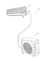
- 1 is an external view of an air conditioner that employs a fan motor that is driven and controlled by a motor drive control device according to the present embodiment.
- the flowchart which shows the flow of control operation which the motor drive control apparatus which concerns on 1st Embodiment performs.
- the timing chart of each signal when a motor rotates to a normal direction by the motor drive control apparatus which concerns on 1st Embodiment The block diagram which showed the whole structure of the system by which the motor drive control apparatus which concerns on the modification of 1st Embodiment was employ
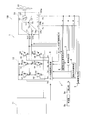
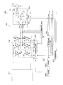
- FIG. 1 is an overall configuration diagram of a motor drive control system 100 including a brushless DC motor 51 and a motor drive control device 1 for controlling the drive of the brushless DC motor 51.
- the brushless DC motor 51 is a fan motor used as a drive source of the propeller fan 61 in the outdoor unit X3 of the air conditioner X1 in FIG. 2 and includes a stator 52, a rotor 53, and three Hall ICs 54u, 54v, 54w ( Equivalent to a position detector).
- the brushless DC motor 51 is simply referred to as a motor 51 for the sake of simplicity.
- the stator 52 includes U-phase, V-phase, and W-phase drive coils Lu, Lv, and Lw that are star-connected. One ends of the U-phase, V-phase, and W-phase drive coils Lu, Lv, and Lw are connected to U-phase, V-phase, and W-phase drive coil terminals TU, TV, and TW, respectively, and the other ends are all terminals TN. It is connected to the.
- These three-phase drive coils Lu, Lv, and Lw generate induced voltages Vun, Vvn, and Vwn (FIG. 6) corresponding to the rotational speed and the position of the rotor 53 when the rotor 53 rotates.
- the rotor 53 includes a two-pole permanent magnet composed of an N pole and an S pole, and rotates about the rotation axis with respect to the stator 52.
- the rotation of the rotor 53 is output to the propeller fan 61 via an output shaft (not shown) that is on the same axis as the rotation shaft.
- the three Hall ICs 54u to 54w are provided so as to correspond to the drive coils Lu, Lv, and Lw, respectively.
- Each Hall IC 54u to 54w detects the position of the rotor 53 with respect to the stator 52 based on the magnetic flux generated by the permanent magnet of the rotor 53.
- the motor drive control device 1 of the present embodiment includes an abnormality detection unit 2, a rotation speed detection unit 3, a rotation direction detection unit 4, a display unit 5a, a reception unit 5b (corresponding to an instruction reception unit), A sensorless position estimation unit 6 and a drive voltage generation unit 7 are provided.
- the abnormality detection unit 2 detects the abnormality of each of the position detection signals Hu to Hw, and determines each Hall IC 54u to 54w in which a malfunction such as a failure has occurred.
- a method of detecting an abnormality in each of the position detection signals Hu to Hw for example, the position detection signals Hu to Hw that are output based on the positions of the Hall ICs 54u to 54w are subjected to a logical operation to be output originally.
- a method for determining whether or not position detection signals Hu to Hw to be output are output, a method for confirming abnormality of the position detection signals Hu to Hw by direct current excitation to the motor 51, and the like.
- the abnormality detection part 2 uses the former method among the methods mentioned above is taken as an example.
- the rotation speed detector 3 measures the rotation speed of the rotor 53 in the motor 51 using the position detection signals Hu to Hw output from the Hall ICs 54u to 54w.
- the rotation speed detection unit 3 detects the position detection signals Hu, Hv.
- the motor 51 uses at least one of the remaining position detection signals Hu, Hv, Hw (that is, position detection signals Hu to Hw output from normal Hall ICs 54 u to 54 w in which no malfunction occurs) except for Hw.
- the number of rotations of the rotor 53 is detected.
- the rotation speed detection unit 3 detects the rotation speed of the rotor 53 in the motor 51 using the position detection signals Hv and Hw.
- the rotation number detection unit 3 determines the rotation number of the rotor 53 in the motor 51 based on all the position detection signals Hu to Hw. Is detected.
- the rotational speed of the rotor 53 in the motor 51 is simply referred to as “the rotational speed of the motor 51”.
- the rotation direction detector 4 detects the rotation direction of the rotor 53 in the motor 51 using the position detection signals Hu to Hw output from the Hall ICs 54u to 54w.
- the rotation direction detection unit 4 uses the remaining position detection signals Hu to Hw excluding the position detection signals Hu to Hw detected as abnormal by the abnormality detection unit 2, like the rotation number detection unit 3.
- the rotation direction of the rotor 53 in the motor 51 is detected.
- the rotation direction detection unit 4 detects the rotation direction of the rotor 53 in the motor 51 using the position detection signals Hv and Hw.
- the rotation direction detection unit 4 determines the rotation direction of the rotor 53 in the motor 51 based on all the position detection signals Hu to Hw. Is detected.
- the display unit 5a displays an abnormality when the abnormality detection unit 2 detects an abnormality in the position detection signals Hu to Hw. As shown in FIG. 2, the display unit 5a displays the indoor unit X2 of the air conditioner X1. Is provided.
- the display unit 5a is configured by, for example, an LED or the like, and lights up or blinks when any one of the position detection signals Hu to Hw is detected.
- the display unit 5a may change the color to be turned on when all the position detection signals Hu to Hw are normal and when one or more position detection signals Hu to Hw are abnormal. Thereby, the user of the indoor unit X2 can know that the Hall ICs 54u to 54w are abnormal.
- the receiving unit 5b is provided in the indoor unit X2 of the air conditioning apparatus X1 as shown in FIG.
- the receiving unit 5b can accept various driving instructions from a user made through a remote controller.
- the receiving unit 5b according to the present embodiment can receive an operation execution instruction of the drive voltage generation unit 7 and an operation stop instruction.
- the execution instruction of the operation of the drive voltage generation unit 7 refers to at least one of the remaining position detection signals Hu to Hw excluding the position detection signals Hu to Hw detected by the drive voltage generation unit 7 as abnormal. Based on this, an operation for generating the drive voltages SU1 to SW1 is described. This operation will be described later under “[drive voltage generator]”.
- the sensorless position estimation unit 6 is for detecting the position of the rotor 53 used when driving the motor 51 by a so-called sensorless system, and includes a position detection comparator and the like. For example, the sensorless position estimation unit 6 determines the position of the rotor 53 relative to the stator 52 based on the induced voltages Vun to Vwn generated in the motor 51 and the neutral point voltage of the motor 51 (specifically, the voltage at the terminal TN of the motor 51). Is detected. That is, the sensorless position estimation unit 6 estimates the position of the rotor 53 without using the position detection signals Hu to Hw.
- the sensorless position estimation unit 6 may function when the abnormality detection unit 2 detects that all the position detection signals Hu to Hw are abnormal while the motor 51 is rotating normally. Further, the sensorless position estimation unit 6 may estimate the position of the rotor 53 regardless of the abnormal state of the position detection signals Hu to Hw. In this embodiment, a case where the sensorless position estimation unit 6 functions when all the position detection signals Hu to Hw are detected to be abnormal is taken as an example. Further, hereinafter, signals indicating the position of the rotor 53 estimated by the sensorless position estimation unit 6 are referred to as sensorless position estimation signals Hu1 ′, Hv1 ′, and Hw1 ′.
- the drive voltage generator 7 generates drive voltages SU 1, SV 1, SW 1 for controlling the drive of the motor 51 and outputs them to the motor 51.
- the drive voltage generation unit 7 according to the present embodiment can drive the motor 51 even when at least one abnormality is detected from the position detection signals Hu to Hw by the abnormality detection unit 2.
- an abnormal position estimating unit 8 a gate control signal generating unit 9, and an output circuit 10.
- the abnormal position estimation unit 8 estimates the position of the rotor 53 using at least one of the remaining position detection signals Hu to Hw excluding the position detection signals Hu to Hw detected as abnormal. In particular, the abnormal position estimation unit 8 estimates the position of the rotor 53 when there are one or two position detection signals Hu to Hw detected as abnormal by the abnormality detection unit 2.
- the abnormal position estimation unit 8 calculates the rotational speed of the rotor 53 based on the time when each of the position detection signals Hv and Hw changes, and the rotational speed of the rotor 53 is calculated. Based on this, the position of the rotor 53 at the location corresponding to the drive coil Lu is estimated.
- signals indicating the position of the rotor 53 estimated by the abnormal position estimation unit 8 in this way are referred to as abnormal position estimation signals Hu2 ′, Hv2 ′, and Hw2 ′.
- the abnormal position estimation signals Hu2 ′ to Hw2 ′ are signals representing the position of the rotor 53 (that is, the electrical angle) itself, or “0” or “1” as in the case of the position detection signals Hu to Hw.
- the case where the abnormal position estimation signals Hu2 ′ to Hw2 ′ are “0” or “1” signals will be described.
- the gate control signal generation unit 9 is composed of, for example, a microcomputer including a CPU and a memory, and an output circuit is provided so that drive voltages SU1 to SW1 corresponding to the rotation speed and rotation direction of the rotor 53 are output to the motor 51.
- the gate control signal generation unit 9 changes the generation method of the gate control signals Gu to Gz according to the detection result by the abnormality detection unit 2.
- the memory constituting the gate control signal generation unit 9 includes a control program for the CPU to determine the gate control signals Gu to Gz, and a signal determination table 1 used when the gate control signals Gu to Gz are generated. , 2 are stored.
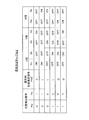
- FIG. 3 shows an example of the signal determination table 1 used when there is no abnormality in all the position detection signals Hu to Hw. In this signal determination table 1, the position detection signals Hu to Hw and the gate control signals Gu to Gz are shown. Are associated.
- FIG. 4 shows an example of the signal determination table 2 used when it is determined that the position detection signal Hw is abnormal. In this signal determination table 2, the position detection signals Hu and Hv, the abnormal position estimation signal Hw2 are shown. 'And the gate control signals Gu to Gz are associated with each other.
- the gate control signal generator 9 applies the position detection signals Hu to Hw to the signal determination table 1 in FIG. Gz is generated.
- the gate control signal generator 9 selects a signal determination table based on the abnormal position detection signals Hu to Hw, and the normal position The detection signals Hu to Hw and the abnormal position estimation signals Hu2 ′ to Hw2 ′ are applied to the selected position determination table 2 to generate gate control signals Gu to Gz. For example, when only one position detection signal Hw is abnormal, the signal determination table 2 in FIG. 3 is selected.
- the gate control signal generation unit 9 generates the gate control signals Gu to Gz based on the abnormal position estimation signal Hw2 ′, the normal position detection signals Hu and Hv, and the selected signal determination table 2 instead of the position detection signal Hw. Is generated.
- the gate control signal generation unit 9 When all the three position detection signals Hu to Hw are abnormal, the gate control signal generation unit 9 does not use the position detection signals Hu to Hw, and the sensorless position estimation estimated by the sensorless position estimation unit 6 is performed. Gate control signals Gu to Gz are generated using the signals Hu1 ′ to Hw1 ′. Further, the gate control signal generation unit 9 further adjusts the gate control signals Gu to Gz according to the rotation number of the motor 51 output from the rotation number detection unit 3. As a result, gate control signals Gu to Gz corresponding to the rotational speed of the motor 51 at that time are generated and output to the insulated gate bipolar transistors Q1 to Q6.
- Output circuit 10 includes insulated gate bipolar transistors (hereinafter simply referred to as transistors) Q1-Q6 and free-wheeling diodes D1-D6.
- the transistors Q1 and Q2, Q3 and Q4, Q5 and Q6 are connected in series between the power supply line to which the power supply voltage from the power supply unit 11 is supplied and the GND line.
- the connection points NU, NV, NW between the transistors Q1 and Q2, Q3 and Q4, Q5 and Q6 are connected to the U-phase, V-phase and W-phase drive coil terminals TU, TV and TW of the motor 51, respectively.
- the diodes D1 to D6 have such characteristics that they are turned on when a reverse voltage is applied to the transistors Q1 to Q6, and are connected in parallel to the transistors Q1 to Q6.
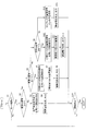
- FIG. 5 is a flowchart showing the flow of control operation performed by the motor drive control device 1.
- the rotational speed, rotation direction and position estimation signals Hu ′ to Hw ′ of the motor 51 are all normal position detection signals Hu to Hw. Take the case of detection and generation from Here, the case where the operation of the drive voltage generation unit 7 described below is automatically performed when an abnormality is detected in the position detection signals Hu to Hw is taken as an example.
- Step S1 When the motor drive control device 1 obtains an instruction to start the motor 51 from the outside of the motor drive control device 1, such as the outdoor unit X3 of the air conditioning device X1, the motor drive control device 1 generates drive voltages SU1 to SW1 and generates the motor 51 (S1). As a result, the motor 51 is started.
- Steps S2 to S4 When no abnormality is detected in all the position detection signals Hu to Hw for three phases (No in S2), the rotation speed detection unit 3 and the rotation direction detection unit 4 detect all the position detection signals Hu to Hw. Is used to detect the rotation speed and rotation direction of the motor 51 (S3).
- the gate control signal generation unit 9 of the drive voltage generation unit 7 generates gate control signals Gu to Gz based on all the position detection signals Hu to Hw, the number of rotations of the motor 51, and the like, and each transistor Q1 to Q6 of the output circuit 10 To output this. As a result, the transistors Q1 to Q6 are turned on and off by the gate control signals Gu to Gz, and the drive voltages SU1 to SW1 output from the output circuit 10 are applied to the drive coils Lu to Lw in the motor 51. (S4).
- Steps S5 to S8 When the position detection signal for one phase among the position detection signals Hu to Hw for three phases is detected to be abnormal (Yes in S5), the rotation speed detection unit 3 and the rotation direction detection unit 4 detects the number of rotations and the direction of rotation of the motor 51 using a signal excluding the position detection signal for one phase detected as abnormal (that is, the position detection signal for two normal phases) (S6). .
- the abnormal position estimation unit 8 of the drive voltage generation unit 7 estimates the position of the abnormal one-phase rotor 53 based on the normal two-phase position detection signals Hu to Hw, and outputs an abnormal position estimation signal. Hu2 ′ to Hw2 ′ are output (S7).
- the gate control signal generator 9 generates the gate control signal based on the normal position detection signals Hu to Hw for two phases, the abnormal position estimation signals Hu2 ′ to Hw2 ′ for one phase, and the rotation speed of the motor 51. Gu to Gz are generated.
- the transistors Q1 to Q6 of the output circuit 10 are turned on and off based on the gate control signals Gu to Gz, and the drive coils Lu to Lw in the motor 51 receive abnormal position detection signals Hu to Hw.
- Drive voltages SU1 to SW1 that are not accompanied are output (S8).
- Steps S9 to S12 When the two-phase position detection signals Hu to Hw among the three phase position detection signals Hu to Hw are detected to be abnormal (Yes in S9), the rotational speed detection unit 3 and the rotation The direction detection unit 4 uses the signals other than the two-phase position detection signals Hu to Hw detected to be abnormal (that is, the normal one-phase position detection signal) and the rotation speed and the rotation direction of the motor 51. Is detected (S10).
- the abnormal position estimation unit 8 estimates the position of the abnormal rotor 53 for two phases based on the normal position detection signals Hu to Hw for one phase, and detects an abnormal position estimation signal Hu2 ′ for two phases. ⁇ Hw2 'is output (S11).
- the gate control signal generator 9 generates a gate control signal based on the normal position detection signals Hu to Hw for one phase, the abnormal position estimation signals Hu2 ′ to Hw2 ′ for two phases, and the rotation speed of the motor 51. Gu to Gz are generated.
- the transistors Q1 to Q6 of the output circuit 10 are turned on and off based on the gate control signals Gu to Gz, and the drive coils Lu to Lw in the motor 51 receive abnormal position detection signals Hu to Hw.
- Drive voltages SU1 to SW1 that are not accompanied are output (S12).
- Steps S13 to S14 When it is detected that all the position detection signals Hu to Hw for three phases are abnormal (No in S9), the sensorless position estimation unit 6 does not use the position detection signals Hu to Hw. The position of the rotor 53 is estimated, and sensorless position estimation signals Hu1 ′ to Hw1 ′ for three phases are output (S13). Then, the gate control signal generation unit 9 generates gate control signals Gu to Gz based on the sensorless position estimation signals Hu1 ′ to Hw1 ′. As a result, the drive voltages SU1 to SW1 based on sensorless drive are output to the motor 51 (S14).
- Step S15 The motor drive control device 1 repeats the operations after step S2 until an instruction to stop the rotation of the motor 51 is acquired from the outside of the motor drive control device 1 (No in S15). In addition, when the rotation stop instruction
- FIG. 6 is a timing chart showing signals output from the motor drive control device 1 and induced voltages Vun and Vwn generated in the drive coils Lu to Lw of the motor 51 when a malfunction occurs in the Hall IC 54u. It is.
- the gate control signals Gu to Gz in FIG. 6 are indicated as “H” when “ON” and “L” when they are “OFF”.
- the position detection signal Hu output from the Hall IC 54u is fixed to either “H” or “L”.
- FIG. 6 shows the case where the position detection signal Hu is fixed at “H”.
- the abnormality detection unit 2 detects an abnormality of the position detection signal Hu.
- the abnormal position estimation unit 8 estimates the position of the rotor 53 based on the normal position detection signals Hv and Hw, and outputs an abnormal position estimation signal Hu2 ′.
- the gate control signal generation unit 9 generates gate control signals Gu to Gz based on the estimated abnormal position estimation signal Hu2 ′ and the position detection signals Hv and Hw, and outputs the gate control signals Gu to G6 to the transistors Q1 to Q6 of the output circuit 10. Output.
- the drive voltages SU1 to SW1 similar to those when the position detection signals Hu to Hw are normal are output to the motor 51.
- the rotation speed of the motor 51 is detected using the normal position detection signals Hu to Hw, and the drive voltages SU1 to SW1 are generated based on the rotation speed of the motor 51. Therefore, the rotation speed control of the motor 51 is more appropriately performed.
- the Hall IC is used as the position detection unit of the motor 51, the position of the rotor can be detected without using a complicated circuit or calculation, so that the cost can be reduced.
- the motor drive control device 1 estimates the position of the rotor without using the position detection signals Hu to Hw, and generates the drive voltages SU1 to SW1. . Therefore, the motor 51 can continue to rotate without being affected by the position detection signals Hu to Hw output from the defective Hall ICs 54u to 54w.
- the motor drive control device 1 since the motor drive control device 1 includes the display unit 5a that displays that the abnormality detection unit 2 has detected the abnormality of the position detection signals Hu to Hw, the user has a problem with the Hall ICs 54u to 54w. I can know that.
- the motor drive control device 1 includes a receiving unit 5b that can receive an instruction to execute the above operation by the drive voltage generating unit 7. Therefore, the user determines whether or not to cause the drive voltage generation unit 7 to perform the above-described operation even when an abnormality has occurred in the Hall ICs 54u to 54w and the display unit 5a indicates that the abnormality has been detected. Can be selected and instructed via remote controller. Further, the motor drive control device 1 performs the generation operation of the drive voltages SU1 to SW1 based on a user instruction even when at least one of the position detection signals Hu to Hw is abnormal, so that the brushless DC motor 51 can be driven.
- FIG. 7 is a configuration diagram of an entire motor drive control system 100 ′ including a motor drive control device 1 ′ according to a modification of the first embodiment and a motor 51 that is driven and controlled by the motor drive control device 1 ′. is there.
- the motor drive control device 1 ′ includes a phase difference detection unit 12 in addition to the configuration of the motor drive control device 1 of FIG.
- the configuration other than the phase difference detection unit 12 is the same as each configuration in the motor drive control system 100 in FIG. 1, and thus the same reference numerals as those in FIG. To do.
- the phase difference detection unit 12 receives the remaining position detection signals Hu to Hw (that is, normal position detection signals Hu to Hw) excluding the position detection signals Hu to Hw detected as abnormal and the normal position detection signals Hu to Hw.
- the phase differences from the induced voltages Vun to Vwn generated in the drive coils Lu to Lw of the motor 51 corresponding to the above are detected.
- the phase difference detection unit 12 calculates the phase difference between the position detection signals Hv and Hw and the induced voltages Vvn and Vwn generated in the drive coils Lv and Lw of the motor 51. To detect.
- the phase difference detection unit 12 detects a phase difference when one or two Hall ICs 54u to 54w are abnormal among the three Hall ICs 54u to 54w. Then, the gate control signal generation unit 9 generates the gate control signals Gu to Gz based on the phase difference detected by the phase difference detection unit 12 and the polarities of the normal position detection signals Hu to Hw. For example, when the position detection signal Hu is abnormal, the gate control signal generation unit 209 determines the gate control signal Gu based on the phase difference regarding the position detection signals Hv and Hw and the polarities of the position detection signals Hv and Hw. ⁇ Gz is generated. In this case, the output voltage is output from the output circuit 210 based on the phase difference regarding the position detection signals Hv and Hw and the polarities of the position detection signals Hv and Hw.
- the motor 51 rotates normally without being affected by the malfunctioned Hall ICs 54u to 54w. can do.
- the motor 51 estimates the position of the rotor 53 by the sensorless position estimation unit 6 and drives based on the estimated position, as in the first embodiment.
- Second Embodiment the drive control method of the motor 51 when an abnormality has occurred in the Hall ICs 54u to 54w while the motor 51 is rotating has been described. In the second embodiment, before the motor 51 is started.
- FIG. 8 is a configuration diagram of an entire motor drive control system 200 including a motor drive control device 101 according to the second embodiment and a motor 51 that is driven and controlled by the motor drive control device 101.
- the motor 51 is an outdoor unit fan motor, and includes a stator 52 including U-phase, V-phase, and W-phase drive coils Lu to Lw, a rotor 53 having a plurality of magnetic poles, and Hall ICs 54u to 54w.
- a three-phase brushless DC motor provided.
- the motor drive control device 101 includes an abnormality detection unit 102, a rotation speed detection unit 103, a rotation direction detection unit 104, a display unit 105a, a reception unit 105b (corresponding to an instruction reception unit), and a sensorless position.
- the drive voltage generation unit 107 includes an abnormal position estimation unit 108, a gate control signal generation unit 109, and an output circuit 110.
- the abnormality detection unit 102, the rotation number detection unit 103, the rotation direction detection unit 104, the display unit 105a, the sensorless position estimation unit 106, the abnormal time position estimation unit 108 of the drive voltage generation unit 107, and the output circuit 110 are described as follows.
- the position determining unit 112 determines a predetermined position of the rotor 53 such that when at least one of the Hall ICs 54u to 54w is abnormal, torque in the forward rotation direction is generated when the drive voltages SU2 to SW2 for starting the motor 51 are applied. To decide.
- the abnormality detection unit 102 detects abnormality of the Hall ICs 54u to 54w before the motor 51 is started. Therefore, the position determination unit 112 performs an operation of determining a predetermined position of the rotor 53 before the motor 51 performs normal rotation, that is, before the motor 51 is started. If an abnormality is detected, a message to that effect is displayed on the display unit 105a.
- the position determination unit 112 determines the predetermined position of the rotor 53.
- drive voltages SU2 to SW2 for starting the motor 51 are generated using all the position detection signals Hu to Hw when the position detection signal Hu output from the Hall IC 54u is abnormal, as shown in FIG.
- an unbalanced period occurs in the drive voltages SU2 to SW2.
- the drive voltages SU2 to SW2 are in a balanced state during a period A of about 210 degrees to about 30 degrees at the position of the rotor 53, and torque is generated in the forward rotation direction.
- the drive voltages SU2 to SW2 are in an unbalanced state during the period B of about 30 degrees to about 210 degrees at the position 53. Therefore, in such a case, the position determination unit 112 determines the predetermined position of the rotor 53 to be a position corresponding to about 210 degrees in the position of the rotor 53. That is, the position determining unit 112 determines the predetermined position of the rotor 53 as a position where the drive voltages SU2 to SW2 applied to the respective phases are in a balanced state.
- the gate control signal generation unit 109 generates gate control signals Gu to Gz for turning on and off the transistors Q1 to Q6 of the output circuit 110. Particularly, when at least one of the Hall ICs 54u to 54w is abnormal, the gate control signal generation unit 109 according to the present embodiment has a rotor at a predetermined position determined by the position determination unit 112 before starting the motor 51. Gate control signals Gu to Gz are generated and output to the transistors Q1 to Q6 so that driving voltages SU2 to SW2 (corresponding to a fixed voltage) such that 53 is fixed are output to the motor 51.
- the gate control signal generation unit 109 generates gate control signals Gu to Gz for exciting the rotor 53 so-called DC excitation before the motor 51 is started.
- the output circuit 110 outputs to the motor 51 drive voltages SU2 to SW2 (that is, fixed voltages) for exciting the rotor 53 by DC excitation and moving the position of the rotor 53 to a predetermined position and fixing it. Is fixed in place.
- the gate control signal generation unit 109 determines the energization period of the drive voltages SU2 to SW2 based on the normal / abnormal state of the position detection signals Hu to Hw.
- the energization period corresponds to a period in which the position detection signals Hu to Hw are normal and the drive voltages SU2 to SW2 applied to the drive coils Lu to Lw of each phase are balanced.
- a period A from about 210 degrees to 30 degrees at the position of the rotor 53 corresponds to a normal period of the position detection signals Hu to Hw.
- the gate control signal generation unit 109 determines that the energization period is about 180 degrees.
- the gate control signal generation unit 109 drives the drive voltage SU2 to SW2 for starting the motor 51. Gate control signals Gu to Gz corresponding to are generated. At this time, the gate control signal generation unit 109 continues to output the gate control signals Gu to Gz during the energization period. Then, drive voltages SU2 to SW2 for starting the motor 51 are output from the output circuit 110 and applied to the motor 51 during the determined energization period. As a result, a torque in the forward rotation direction is generated in the motor 51, and the motor 51 can be activated using the generated torque (ie, inertia force).
- the motor drive control device 101 may perform drive control using the method according to the first embodiment.
- the motor drive control apparatus 101 uses the position detection signals Hu to Hw to start the motor 51 in order to start the motor 51 normally. Voltages SU2 to SW2 are generated and output to the motor 51.
- the receiving unit 105b can accept various driving instructions from the user made through the remote controller, like the receiving unit 5b according to the first embodiment.
- the receiving unit 105b receives an instruction to execute a predetermined position of the rotor by the position determining unit 112 and an instruction to execute the operation of generating the drive voltages SU2 to SW2 by the drive voltage generating unit 107 and an instruction to stop these operations. be able to.
- the drive voltage generation unit 107 may automatically perform the above-described operation when the position detection signals Hu to Hw are abnormal, and receives an execution instruction from the user. You may perform only when the part 105b receives.
- (2) Effect (A) When it is known in advance that the Hall ICs 54u to 54w have failed before the motor 51 is started, the motor drive control device 101 generates torque in the forward rotation direction of the rotor 53 by direct current excitation. After moving and fixing to a predetermined position, the motor 51 is started. As a result, immediately after the motor 51 is started, torque in the forward rotation direction is generated in the motor 51, so that the motor 51 can be started reliably.
- the motor drive control device 101 can be used when the load on the motor 51 is relatively large.
- the motor 51 after startup may be affected by the position detection signals Hu to Hw output from the abnormal Hall ICs 54u to 54w.
- the motor drive control device 101 outputs drive voltages SU2 to SW2 for starting the motor 51 during the energization period determined based on the normal / abnormal state of the position detection signals Hu to Hw. Stops the output of the drive voltages SU2 to SW2. As a result, the motor 51 is not affected by the abnormal position detection signals Hu to Hw after startup.
- the energization period is a period in which the position detection signals Hu to Hw are normal.
- the drive voltages SU2 to SW2 for starting the motor 51 are output to the motor 51 during a period in which the position detection signals Hu to Hw are normal.
- the abnormality detection unit 102 detects the abnormality of the Hall ICs 54u to 54w before the motor 51 is activated, so that the motor 51 is affected by the abnormal position detection signals Hu to Hw immediately after the activation. Can rotate without receiving.
- the motor drive control device 101 can receive an instruction to execute the operation by the drive voltage generation unit 107 via a remote controller. Therefore, even if the user has an abnormality in the Hall ICs 54u to 54w and the display unit 105a indicates that the abnormality has been detected, the user determines whether or not to cause the drive voltage generation unit 107 to perform the above-described operation. Can be selected and instructed via remote controller.
- the motor drive control device 101 can activate the brushless DC motor 51 by performing the above operation based on the user's instruction even when at least one of the Hall ICs 54u to 54w is abnormal.
- the motor drive control device 101 drives and controls the fan motor 51 to which the propeller fan 61 is connected as a load.
- the motor 51 having a relatively large inertia that is, the motor 51 to which a relatively large load is connected
- the above effects are further improved.
- Can play for example, as described in effect (A), since the motor 51 is activated using so-called inertia force, the effect of reliably starting the motor 51 as the load connected to the motor 51 increases. You can play more.
- FIG. 10 is a configuration diagram of an entire motor drive control system 300 including a motor drive control device 201 according to the third embodiment and a motor 51 that is driven and controlled by the motor drive control device 201.
- the motor 51 according to the present embodiment has the same configuration as the motor 51 of the first embodiment, the same reference numerals as those in FIG. 1 are given.
- the motor 51 is an outdoor unit fan motor, and includes a stator 52 including U-phase, V-phase, and W-phase drive coils Lu to Lw, a rotor 53 having a plurality of magnetic poles, and Hall ICs 54u to 54w.
- a three-phase brushless DC motor provided.
- the motor drive control device 201 activates the motor 51 by sensorless drive when a malfunction occurs in at least one of the Hall ICs 54u to 54w before the motor 51 is activated.
- a motor drive control device 201 includes an abnormality detection unit 202, a rotation speed detection unit 203, a rotation direction detection unit 204, a display unit 205a, a reception unit 205b (corresponding to an instruction reception unit), a sensorless A position estimation unit 206 and a drive voltage generation unit 207 are provided.
- the drive voltage generation unit 207 includes a gate control signal generation unit 209 and an output circuit 210.
- the abnormality detection unit 202, the rotation number detection unit 203, the rotation direction detection unit 204, the display unit 205a, and the output circuit 210 of the drive voltage generation unit 207 are shown in FIG. 1 with the same names in the first embodiment. Since it has the same configuration as the output circuit 10 of the abnormality detection unit 2, the rotation number detection unit 3, the rotation direction detection unit 4, the display unit 5a, and the drive voltage generation unit 7 according to FIG.
- the sensorless position estimation unit 206, the gate control signal generation unit 109, and the reception unit 205b which are one feature of the present embodiment, will be described.
- the sensorless position estimation unit 206 includes a position detection comparator and the like, and includes induced voltages Vun to Vwn generated in the motor 51 and a neutral point voltage of the motor 51 (specifically, a terminal TN of the motor 51). The position of the rotor 53 relative to the stator 52 is detected based on the voltage of That is, the sensorless position estimation unit 206 estimates the position of the rotor 53 without using the position detection signals Hu to Hw. Note that the sensorless position estimation unit 206 may always function regardless of whether or not at least one of the position detection signals Hu to Hw is abnormal.
- the gate control signal generation unit 209 When all the Hall ICs 54u to 54w are normal, the gate control signal generation unit 209 generates the gate control signals Gu to Gz based on the position detection signals Hu to Hw output from the Hall ICs 54u to 54w. The gate control signal generation unit 209 generates the gate control signals Gu to Gz regardless of the position of the rotor 53 when at least one of the Hall ICs 54u to 54w is abnormal. At this time, the output voltage 210 outputs drive voltages SU3 to SW3 for starting the motor 51 regardless of the position of the rotor 53.
- the gate control signal generation unit 209 performs a so-called synchronous operation in which a predetermined voltage capable of starting the motor 51 is output at a predetermined frequency regardless of the position of the rotor 53 as the drive voltages SU3 to SW3. . At this time, the gate control signal generator 209 can smoothly accelerate the motor 51 by gradually increasing the predetermined voltage and the predetermined frequency. Furthermore, as described in the second embodiment, by fixing the rotor 53 at a predetermined position before starting the motor 51, the rotor 53 does not reverse at the start of the subsequent synchronous operation, so that the start is smoother. And acceleration is possible.
- the gate control signal generation unit 209 generates the gate control signals Gu to Gz based on the position of the rotor 53 estimated by the sensorless position estimation unit 206 when the induced voltage of the motor 51 is generated after the motor 51 is started. Generate. At this time, the output voltage 210 outputs drive voltages SU3 to SW3 for normally rotating the motor 51, and the display unit 205a displays that an abnormality has been detected.
- the receiving unit 205b can accept various driving instructions from the user made through the remote controller, similarly to the receiving units 5b and 105b according to the first and second embodiments. In particular, the receiving unit 205b instructs the execution of the operation for generating the drive voltages SU3 to SW3 by the drive voltage generation unit 207 (that is, the operation for generating the drive voltages SU3 to SW3 by the gate control signal generation unit 209), and these operations. Can receive a stop instruction.
- the receiving unit 205b generates drive voltages SU3 to SW3 for starting the brushless DC motor 51 regardless of the position of the rotor 53 when the brushless DC motor 51 is started, and the brushless DC motor 51. After the activation, an instruction to execute an operation for generating the drive voltages SU3 to SW3 based on the estimated position of the rotor 53 can be received.
- the drive voltage generation unit 207 may automatically perform the above-described operation when the position detection signals Hu to Hw are abnormal, or may be executed by the user.
- the instruction may be given only when the receiving unit 205b receives the instruction.
- the motor drive control device 201 performs sensorless drive on the motor 51 when any one of the Hall ICs 54u to 54w is abnormal. Therefore, even when at least one of the Hall ICs 54u to 54w is already abnormal before the motor 51 is started, or when at least one of the Hall ICs 54u to 54w is abnormal during normal rotation of the motor 51, the motor 51 It can be activated and driven without being affected by the abnormal Hall ICs 54u to 54w.
- the motor drive control device 201 can receive an instruction to execute the operation by the drive voltage generation unit 207 via a remote controller. Therefore, the user determines whether or not to cause the drive voltage generation unit 207 to perform the above-described operation even when an abnormality has occurred in the Hall ICs 54u to 54w and the display unit 205a indicates that the abnormality has been detected. Can be selected and instructed via remote controller.
- the motor drive control device 201 can start and drive the brushless DC motor 51 by performing the above-described operation based on a user instruction even when at least one of the Hall ICs 54u to 54w is abnormal. .
- the maximum number of normal position detection signals Hu to Hw is used (that is, when there are two abnormal position detection signals Hu to Hw, two positions are detected).
- the drive voltages SU1 to SW1 are generated (using the detection signals Hu to Hw) has been described, the present invention is not limited to this.
- the drive voltages SU1 to SW1 may be generated using one position detection signal Hu to Hw.
- the motor 51 can be rotated more reliably by generating the drive voltages SU1 to SW1 using many normal position detection signals Hu to Hw.
- the position estimation units 8 and 108 at the time of abnormality perform position estimation, and the result is used for generating the drive voltage.
- the drive voltage may be generated using only the normal position detection signals Hu to Hw even if the position estimation by the abnormal position estimation units 8 and 108 is not performed.
- the drive voltage is generated when the number of normal position detection signals Hu to Hw is one or two. There is a method in which the pattern of the driving voltage to be set is set in advance.
- the brushless DC motor 51 is selected from the drive voltage patterns set in advance based on the remaining normal position detection signals Hu to Hw. A drive voltage pattern to be output is selected, and the selected drive voltage pattern is generated and output to the brushless DC motor 51.
- the drive voltage generator 7 selects a pattern of the drive voltages SU1 to SW1 based on the position detection signals Hv and Hv that are not abnormal.
- the embodiment in this case will be described with reference to FIG. 6 described above.
- the position detection signals are only “Hv” and “Hw”, the combination of the position detection signals is any when the signals are both “0”.
- the drive voltage generation unit 7 has patterns of the drive voltages SU1 to SW1 corresponding to the four patterns (FIG. 6).
- the drive voltage generator 7 selects the energization pattern “1”, the position detection signal Hv is “0”, and the position detection signal Hw is “1”. In the case of “1”, the energization pattern “2” is selected.
- the pattern of the drive voltages SU1 to SW1 There are four energization patterns. That is, when all three position detection signals Hu, Hv, and Hw are normal, there are six energization patterns.
- the energization pattern is 2 than the original six patterns. There will be 4 streets with fewer streets. For this reason, the energization widths of the drive voltages SU1 to SU1 are not uniform 120 degrees, and are 60 degrees, 120 degrees, and 180 degrees depending on the phase, and the values of the drive voltages SU1 to SW1 vary depending on the phase. Then, since the drive voltages SU1 to SW1 are in positive and negative balance, the brushless DC motor 51 can operate stably.
- a function unit that estimates the position of the rotor 53 when one or two Hall ICs 54u to 54w are abnormal specifically, abnormal (Time position estimation unit) and a functional unit (specifically, a sensorless position estimation unit) that estimates the position of the rotor 53 during sensorless driving are described separately.
- the position estimation of the rotor 53 when one or two Hall ICs 54u to 54w are abnormal and the position estimation of the rotor 53 at the time of sensorless driving may be performed by one functional unit.
- one functional unit for estimating the position of the rotor 53 may be provided without dividing the function unit for sensorless driving and for other than sensorless driving, so that the motor drive control device itself can be made relatively small. it can.
- the drive voltage generation unit 107 generates a drive voltage for fixing the rotor 53 at a predetermined position (that is, a fixed voltage) and generates a drive voltage for starting the motor 51.
- the functional units that generate these types of drive voltages may be configured separately. That is, a fixed voltage generating unit that generates a driving voltage (that is, a fixed voltage) for fixing the rotor 53 at a predetermined position and a driving voltage generating unit that generates a driving voltage for starting the motor 51 are separately provided. It may be provided.
- the drive voltage generation unit 107 performs so-called synchronous operation in which a predetermined voltage capable of starting the motor 51 is output at a predetermined frequency. You may do it. At this time, the drive voltage generation unit 107 can accelerate the motor 51 smoothly by gradually increasing the predetermined voltage and the predetermined frequency.
- the case where the sensorless position estimation unit 206 estimates the position of the rotor 51 based on the induced voltage of the motor 51 has been described.
- the method by which the sensorless position estimation unit 206 estimates the position of the rotor 51 is not limited to this method.
- Other methods for estimating the position of the rotor 51 include a method for estimating the position of the rotor 53 by superimposing high-frequency signals on the drive voltages SU3 to SW3 and outputting them to the motor 51, an electrical model of the motor 51, and a motor.
- a method for estimating the position of the rotor 51 based on the voltage applied to the motor 51 or the current flowing through the motor 51 may be used.
- the motor drive control device can be applied as a device for controlling the drive of a brushless motor or a ventilation fan motor used as a rotational drive source such as a compressor and a fan in an air conditioner.
Landscapes
- Engineering & Computer Science (AREA)
- Power Engineering (AREA)
- Control Of Motors That Do Not Use Commutators (AREA)
Abstract
ブラシレスモータにおいて位置検出センサに不具合が生じた場合でも、モータを回転駆動させることができるモータ駆動制御装置を提供する。ステータ(52)、ロータ(53)及びホールIC(54u~54w)を有するブラシレスDCモータ(51)の駆動を制御するモータ駆動制御装置(1)は、異常検出部(2)と、駆動電圧生成部(7)とを備える。異常検出部(2)は、位置検出信号(Hu~Hw)それぞれの異常を検出する。駆動電圧生成部(7)は、異常検出部(2)により少なくとも1つの位置検出信号(Hu~Hw)の異常が検出された場合、異常と検出された位置検出信号(Hu~Hw)を除く残りの位置検出信号(Hu~Hw)のうち少なくとも1つに基づいて、ブラシレスモータ(51)を駆動させるための駆動電圧(SU1~SW1)を生成してブラシレスモータ(51)に出力する。
Description
本発明は、モータ駆動制御装置、特に、回転子の位置を検出する位置検出部の信号に基づいてブラシレスDCモータの駆動を制御するモータ駆動制御装置に関する。
近年、圧縮機やファン等の機器を備えた空気調和装置では、これらの機器の動力源として例えば3相のブラシレスDCモータが用いられている。
一般的に、3相のブラシレスDCモータは、複数の磁極を有する永久磁石からなる回転子(以下、ロータという)と、3相の駆動コイルを有する固定子(以下、ステータという)とを有している。このようなブラシレスDCモータの駆動コイルには、ステータに対するロータの位置に応じた駆動電圧が、このモータを駆動制御するためのモータ駆動制御装置により印加される。これにより、駆動コイルにはこの駆動電圧に応じた電流が流れて磁界が発生し、ロータが回転する。
ここで、ステータに対するロータの位置を検知する方法には、3相の駆動コイルそれぞれに対応するように配置された3つのロータ位置検出センサを用いた方法が良く用いられている。このロータ位置検出センサは、ロータの永久磁石により生じた磁界に基づいて、ステータに対するロータの相対位置を検出するためのものであって、具体的には、ホール素子やホールIC等が挙げられる。しかし、このような位置検出センサに故障等の不具合が生じると、不具合の生じた位置検出センサは、ロータの位置を正常には検出できなくなる。この場合、モータ駆動制御装置は、例えば1周期のうち半周期は正常な波形を有するが、残りの半周期は位相がずれた波形を有するような駆動電圧をモータに印加してしまう。すると、モータに通電される電流が増加したり、モータの騒音及び振動が増大したりする他、モータの回転が不安定になる恐れがある。
一般的に、3相のブラシレスDCモータは、複数の磁極を有する永久磁石からなる回転子(以下、ロータという)と、3相の駆動コイルを有する固定子(以下、ステータという)とを有している。このようなブラシレスDCモータの駆動コイルには、ステータに対するロータの位置に応じた駆動電圧が、このモータを駆動制御するためのモータ駆動制御装置により印加される。これにより、駆動コイルにはこの駆動電圧に応じた電流が流れて磁界が発生し、ロータが回転する。
ここで、ステータに対するロータの位置を検知する方法には、3相の駆動コイルそれぞれに対応するように配置された3つのロータ位置検出センサを用いた方法が良く用いられている。このロータ位置検出センサは、ロータの永久磁石により生じた磁界に基づいて、ステータに対するロータの相対位置を検出するためのものであって、具体的には、ホール素子やホールIC等が挙げられる。しかし、このような位置検出センサに故障等の不具合が生じると、不具合の生じた位置検出センサは、ロータの位置を正常には検出できなくなる。この場合、モータ駆動制御装置は、例えば1周期のうち半周期は正常な波形を有するが、残りの半周期は位相がずれた波形を有するような駆動電圧をモータに印加してしまう。すると、モータに通電される電流が増加したり、モータの騒音及び振動が増大したりする他、モータの回転が不安定になる恐れがある。
そこで、例えば特許文献1(特開平8-331886号公報)や特許文献2(特開2000-184774号公報)に示すように、位置検出センサに不具合が生じているか否かを検出するモータ駆動制御装置が知られている。特許文献1や特許文献2のモータ駆動制御装置は、位置検出センサに不具合があると検出した場合、モータの駆動を停止する。
ところで、モータの用途等によっては、位置検出センサに不具合が生じた場合であっても、モータを継続して回転させることが必要となる場合がある。しかしながら、このような場合において特許文献1及び特許文献2のモータ駆動制御装置を適用すると、位置検出センサに不具合が生じた場合にはモータの回転が停止してしまうため、モータを継続して回転させることが困難となる。
そこで、本発明は、ブラシレスDCモータにおいて、位置検出センサに不具合が生じた場合でも、モータを回転駆動させることができるモータ駆動制御装置の提供を目的とする。
そこで、本発明は、ブラシレスDCモータにおいて、位置検出センサに不具合が生じた場合でも、モータを回転駆動させることができるモータ駆動制御装置の提供を目的とする。
発明1に係るモータ駆動制御装置は、駆動コイルを有する固定子と、複数の磁極を有する回転子と、固定子に対する回転子の位置を示す位置検出信号を出力する複数の位置検出部とを含むブラシレスDCモータの駆動を制御するモータ駆動制御装置であって、異常検出部と、駆動電圧生成部とを備える。異常検出部は、位置検出信号それぞれの異常を検出する。駆動電圧生成部は、異常検出部により少なくとも1つの位置検出信号の異常が検出された場合、異常と検出された位置検出信号を除く残りの位置検出信号のうち少なくとも1つに基づいて、ブラシレスDCモータを駆動させるための駆動電圧を生成してブラシレスDCモータに出力する。
このモータ駆動制御装置によると、少なくとも1つの位置検出部に故障等の不具合が生じたために、その位置検出部から出力される位置検出信号に異常がある場合、ブラシレスDCモータには、異常でない残りの位置検出信号のうち少なくとも1つに基づいて生成された駆動電圧が出力される。このように、異常である位置検出信号は用いられずに駆動電圧が生成されるため、ブラシレスDCモータは、異常である位置検出信号の影響を受けることなく、安定して回転することができる。
このモータ駆動制御装置によると、少なくとも1つの位置検出部に故障等の不具合が生じたために、その位置検出部から出力される位置検出信号に異常がある場合、ブラシレスDCモータには、異常でない残りの位置検出信号のうち少なくとも1つに基づいて生成された駆動電圧が出力される。このように、異常である位置検出信号は用いられずに駆動電圧が生成されるため、ブラシレスDCモータは、異常である位置検出信号の影響を受けることなく、安定して回転することができる。
発明2に係るモータ駆動制御装置は、発明1に係るモータ駆動制御装置であって、駆動電圧生成部は、異常と検出された位置検出信号を除く残りの位置検出信号のうち少なくとも1つを用いて、回転子の位置を推定する。そして、駆動電圧生成部は、推定した回転子の位置に基づいて駆動電圧を生成する。
このモータ駆動制御装置によると、異常である位置検出信号を用いて駆動電圧が生成されるかわりに、推定した回転子の位置に基づいて駆動電圧が生成される。これにより、ブラシレスDCモータは、より安定して回転を行うことができる。
このモータ駆動制御装置によると、異常である位置検出信号を用いて駆動電圧が生成されるかわりに、推定した回転子の位置に基づいて駆動電圧が生成される。これにより、ブラシレスDCモータは、より安定して回転を行うことができる。
発明3に係るモータ駆動制御装置は、発明1に係るモータ駆動制御装置であって、駆動電圧生成部は、異常と検出された位置検出信号を除く残りの位置検出信号の少なくとも1つに基づいて、予め設定されている駆動電圧のパターンの中からブラシレスDCモータに出力されるべき駆動電圧のパターンを選択し、ブラシレスDCモータに出力する。
ここで、位置検出信号が“1”または“0”の値を採る信号であって、異常であるために使用しないとする位置検出信号が1つである場合を例に採る。このモータ駆動制御装置によると、正常な2つの位置検出信号の値が共に“1”である場合には、駆動電圧のパターンとして「パターン1」が選択され、正常な2つの位置検出信号の値がそれぞれ“0”“1”である場合には、駆動電圧のパターンとして「パターン2」が選択される。3つの位置検出信号全てが正常であれば、駆動電圧のパターンは6通りであるが、上述したように正常な位置検出信号が2つであれば、駆動電圧のパターンは4通りとなる。そのため、ブラシレスDCモータに出力される駆動電圧の通電幅は120度均一ではなく、相により60度、120度、180度となり、駆動電圧の値も相により異なる値となるが、各相毎に着目すると、ブラシレスDCモータに出力される駆動電圧は正負平衡するため、ブラシレスDCモータは安定した動作が可能となる。
ここで、位置検出信号が“1”または“0”の値を採る信号であって、異常であるために使用しないとする位置検出信号が1つである場合を例に採る。このモータ駆動制御装置によると、正常な2つの位置検出信号の値が共に“1”である場合には、駆動電圧のパターンとして「パターン1」が選択され、正常な2つの位置検出信号の値がそれぞれ“0”“1”である場合には、駆動電圧のパターンとして「パターン2」が選択される。3つの位置検出信号全てが正常であれば、駆動電圧のパターンは6通りであるが、上述したように正常な位置検出信号が2つであれば、駆動電圧のパターンは4通りとなる。そのため、ブラシレスDCモータに出力される駆動電圧の通電幅は120度均一ではなく、相により60度、120度、180度となり、駆動電圧の値も相により異なる値となるが、各相毎に着目すると、ブラシレスDCモータに出力される駆動電圧は正負平衡するため、ブラシレスDCモータは安定した動作が可能となる。
発明4に係るモータ駆動制御装置は、発明1~3のいずれかに係るモータ駆動制御装置であって、回転数検出部を更に備える。回転数検出部は、異常と検出された位置検出信号を除く残りの位置検出信号の少なくとも1つを用いて、回転子の回転数を検出する。そして、駆動電圧生成部は、回転数検出部により検出された回転子の回転数に基づいて、駆動電圧を生成する。
このモータ駆動制御装置によると、異常でない位置検出信号を用いて回転数が検出され、その回転数に基づいて駆動電圧が生成されるため、ブラシレスDCモータの回転数制御はより適切に行われるようになる。
このモータ駆動制御装置によると、異常でない位置検出信号を用いて回転数が検出され、その回転数に基づいて駆動電圧が生成されるため、ブラシレスDCモータの回転数制御はより適切に行われるようになる。
発明5に係るモータ駆動制御装置は、発明1~4のいずれかに係るモータ駆動制御装置であって、位置検出部は、ホール素子及びホールICのいずれか1つである。
これにより、複雑な回路や演算を用いなくても、回転子の位置を検出することができるため、コストを削減することができる。
これにより、複雑な回路や演算を用いなくても、回転子の位置を検出することができるため、コストを削減することができる。
発明6に係るモータ駆動制御装置は、発明1~5のいずれかに係るモータ駆動制御装置であって、位相差検出部を更に備える。位相差検出部は、異常と検出された位置検出信号を除く残りの位置検出信号と、残りの位置検出信号に対応する駆動コイルそれぞれに発生する誘起電圧との位相差を検出する。そして、駆動電圧生成部は、位相差と、残りの位置検出信号の極性とに基づいて、駆動電圧を生成する。
このモータ駆動制御装置によると、例えば仕様が不明である位置検出部に不具合が生じても、ブラシレスDCモータは、異常である位置検出信号の影響を受けることなく回転することができる。
このモータ駆動制御装置によると、例えば仕様が不明である位置検出部に不具合が生じても、ブラシレスDCモータは、異常である位置検出信号の影響を受けることなく回転することができる。
発明7に係るモータ駆動制御装置は、発明1~5のいずれかに係るモータ駆動制御装置であって、センサレス位置推定部を更に備える。センサレス位置推定部は、全ての位置検出信号が異常と検出された場合、位置検出信号を用いずに回転子の位置を推定する。そして、駆動電圧生成部は、センサレス位置推定部が回転子の位置を推定した場合、位置検出信号を用いずに、推定された回転子の位置を用いて駆動電圧を生成する。
このモータ駆動制御装置によると、位置検出部全てに不具合が生じた場合であっても、不具合の生じている位置検出部から出力される位置検出信号の影響を受けることなく、ブラシレスDCモータは回転を継続することができる。
このモータ駆動制御装置によると、位置検出部全てに不具合が生じた場合であっても、不具合の生じている位置検出部から出力される位置検出信号の影響を受けることなく、ブラシレスDCモータは回転を継続することができる。
発明8に係るモータ駆動制御装置は、発明1~6のいずれかに係るモータ駆動制御装置であって、駆動電圧生成部は、位置検出信号の正常/異常の状態に基づいて駆動電圧の通電期間を決定する。そして、駆動電圧生成部は、通電期間の間、駆動電圧を出力する。
位置検出部の少なくとも1つが異常であると、起動後のブラシレスDCモータは、異常である位置検出部から出力される位置検出信号の影響を受ける場合がある。すると、ブラシレスDCモータに通電する電流の増加や騒音、振動などが生じてしまう。しかし、このモータ駆動制御装置は、位置検出信号の正常/異常の状態に基づいて決定した通電期間の間は駆動電圧を出力し、通電期間以外は例えば駆動電圧の出力を停止する。これにより、ブラシレスDCモータは、起動後、異常である位置検出信号の影響を受けずに済む。
位置検出部の少なくとも1つが異常であると、起動後のブラシレスDCモータは、異常である位置検出部から出力される位置検出信号の影響を受ける場合がある。すると、ブラシレスDCモータに通電する電流の増加や騒音、振動などが生じてしまう。しかし、このモータ駆動制御装置は、位置検出信号の正常/異常の状態に基づいて決定した通電期間の間は駆動電圧を出力し、通電期間以外は例えば駆動電圧の出力を停止する。これにより、ブラシレスDCモータは、起動後、異常である位置検出信号の影響を受けずに済む。
発明9に係るモータ駆動制御装置は、発明8に係るモータ駆動制御装置であって、通電期間は、位置検出信号が正常な期間である。
これにより、駆動電圧は、位置検出信号が正常な期間において、ブラシレスDCモータに出力されるようになる。
これにより、駆動電圧は、位置検出信号が正常な期間において、ブラシレスDCモータに出力されるようになる。
発明10に係るモータ駆動制御装置は、発明1~9のいずれかに係るモータ駆動制御装置であって、位置決定部を更に備える。位置決定部は、ブラシレスDCモータの起動時、駆動電圧を印加した時に正回転方向へのトルクが発生するような回転子の所定位置を決定する。そして、駆動電圧生成部は、回転子が所定位置に移動するような駆動電圧を生成し、回転子が所定位置に移動した後、ブラシレスDCモータを起動させるための駆動電圧を生成する。
このモータ駆動制御装置は、ブラシレスDCモータの起動前に、位置検出部が故障していると予め分かっている場合には、例えば直流励磁によりブラシレスDCモータを所定位置に移動させた後にブラシレスDCモータを起動させる。これにより、ブラシレスDCモータの起動直後、ブラシレスDCモータには正回転方向へのトルクが発生し、その後慣性を利用してブラシレスDCモータが起動するため、ブラシレスDCモータは確実に起動することができる。
このモータ駆動制御装置は、ブラシレスDCモータの起動前に、位置検出部が故障していると予め分かっている場合には、例えば直流励磁によりブラシレスDCモータを所定位置に移動させた後にブラシレスDCモータを起動させる。これにより、ブラシレスDCモータの起動直後、ブラシレスDCモータには正回転方向へのトルクが発生し、その後慣性を利用してブラシレスDCモータが起動するため、ブラシレスDCモータは確実に起動することができる。
発明11に係るモータ駆動制御装置は、発明1~10のいずれかに係るモータ駆動制御装置であって、異常検出部は、ブラシレスDCモータの起動前に位置検出信号の異常検出を行う。
これにより、ブラシレスDCモータは、起動直後から異常な位置検出信号の影響を受けずに済む。
これにより、ブラシレスDCモータは、起動直後から異常な位置検出信号の影響を受けずに済む。
発明12に係るモータ駆動制御装置は、発明1~11のいずれかに係るモータ駆動制御装置であって、表示部を更に備える。表示部は、異常検出部が位置検出信号の異常を検出したことを表示することができる。
これにより、利用者は、位置検出部に不具合が生じていることを知ることができる。
これにより、利用者は、位置検出部に不具合が生じていることを知ることができる。
発明13に係るモータ駆動制御装置は、発明1~12のいずれかに係るモータ駆動制御装置であって、指示受付部を更に備える。指示受付部は、異常と検出された位置検出信号を除く残りの位置検出信号のうち少なくとも1つに基づいて、駆動電圧が生成される動作の実行指示を受け付けることができる。
このモータ駆動制御装置によると、指示受付部は、駆動電圧が生成される動作の実行指示を、例えばリモートコントローラを介して利用者から受け付けることができる。そして、モータ駆動制御装置は、この実行指示を受け付けた場合、異常である位置検出信号を除く残りの位置検出信号のうち少なくとも1つに基づいて、駆動電圧を生成することができる。したがって、モータ駆動制御装置は、位置検出信号のうち少なくとも1つが異常である場合にも、利用者の指示に基づいて上記駆動電圧の生成動作行うことで、ブラシレスDCモータを駆動することができる。
このモータ駆動制御装置によると、指示受付部は、駆動電圧が生成される動作の実行指示を、例えばリモートコントローラを介して利用者から受け付けることができる。そして、モータ駆動制御装置は、この実行指示を受け付けた場合、異常である位置検出信号を除く残りの位置検出信号のうち少なくとも1つに基づいて、駆動電圧を生成することができる。したがって、モータ駆動制御装置は、位置検出信号のうち少なくとも1つが異常である場合にも、利用者の指示に基づいて上記駆動電圧の生成動作行うことで、ブラシレスDCモータを駆動することができる。
発明14に係るモータ駆動制御装置は、駆動コイルを有する固定子と、複数の磁極を有する回転子と、固定子に対する回転子の位置を示す位置検出信号を出力する複数の位置検出部とを含むブラシレスDCモータの駆動を制御するモータ駆動制御装置であって、位置決定部と、固定電圧生成部と、駆動電圧生成部とを備える。位置決定部は、位置検出部の少なくとも1つが異常である場合、ブラシレスDCモータを起動させるための駆動電圧の印加時に正回転方向へのトルクが発生するような回転子の所定位置を決定する。固定電圧生成部は、回転子が所定位置に固定されるような固定電圧を生成してブラシレスDCモータに出力する。駆動電圧生成部は、回転子が所定位置に固定された後、駆動電圧を生成してブラシレスDCモータに出力する。
このモータ駆動電圧生成装置は、ブラシレスDCモータの起動前に、位置検出部が故障していると予め分かっている場合には、例えば直流励磁によりブラシレスDCモータを所定位置に移動させ固定させた後にモータを起動させる。これにより、ブラシレスDCモータの起動直後、ブラシレスDCモータには正回転方向へのトルクが発生し、その後慣性を利用してブラシレスDCモータが起動するため、ブラシレスDCモータは確実に起動することができる。
このモータ駆動電圧生成装置は、ブラシレスDCモータの起動前に、位置検出部が故障していると予め分かっている場合には、例えば直流励磁によりブラシレスDCモータを所定位置に移動させ固定させた後にモータを起動させる。これにより、ブラシレスDCモータの起動直後、ブラシレスDCモータには正回転方向へのトルクが発生し、その後慣性を利用してブラシレスDCモータが起動するため、ブラシレスDCモータは確実に起動することができる。
発明15に係るモータ駆動制御装置は、発明14に係るモータ駆動制御装置であって、駆動電圧生成部は、位置検出信号の正常/異常の状態に基づいて駆動電圧の通電期間を決定し、通電期間の間駆動電圧を出力する。
位置検出部の少なくとも1つが異常であると、起動後のブラシレスDCモータは、異常である位置検出部から出力される位置検出信号の影響を受ける場合がある。すると、ブラシレスDCモータに通電する電流の増加や騒音、振動などが生じてしまう。しかし、このモータ駆動制御装置は、位置検出信号の正常/異常の状態に基づいて決定した通電期間の間は駆動電圧を出力し、通電期間以外は例えば駆動電圧の出力を停止する。これにより、ブラシレスDCモータは、起動後、異常である位置検出信号の影響を受けずに済む。
位置検出部の少なくとも1つが異常であると、起動後のブラシレスDCモータは、異常である位置検出部から出力される位置検出信号の影響を受ける場合がある。すると、ブラシレスDCモータに通電する電流の増加や騒音、振動などが生じてしまう。しかし、このモータ駆動制御装置は、位置検出信号の正常/異常の状態に基づいて決定した通電期間の間は駆動電圧を出力し、通電期間以外は例えば駆動電圧の出力を停止する。これにより、ブラシレスDCモータは、起動後、異常である位置検出信号の影響を受けずに済む。
発明16に係るモータ駆動制御装置は、発明15に係るモータ駆動制御装置であって、通電期間は、位置検出信号が正常な期間である。
これにより、駆動電圧は、位置検出信号が正常な期間において、ブラシレスDCモータに出力されるようになる。
これにより、駆動電圧は、位置検出信号が正常な期間において、ブラシレスDCモータに出力されるようになる。
発明17に係るモータ駆動制御装置は、発明14~16のいずれかに係るモータ駆動制御装置であって、異常検出部を更に備える。異常検出部は、ブラシレスDCモータの起動前に位置検出部の異常検出を行う。
これにより、ブラシレスDCモータは、起動直後から異常な位置検出信号の影響を受けることなく回転することができる。
これにより、ブラシレスDCモータは、起動直後から異常な位置検出信号の影響を受けることなく回転することができる。
発明18に係るモータ駆動制御装置は、発明17に係るモータ駆動制御装置であって、表示部を更に備える。表示部は、異常検出部が位置検出部の異常を検出した旨を表示することができる。
これにより、利用者は、位置検出部に不具合が生じていることを知ることができる。
これにより、利用者は、位置検出部に不具合が生じていることを知ることができる。
発明19に係るモータ駆動制御装置は、発明14~18のいずれかに係るモータ駆動制御装置であって、指示受付部を更に備える。指示受付部は、位置決定部による回転子の所定位置の決定動作、固定電圧生成部による固定電圧の生成動作及び駆動電圧生成部による駆動電圧の生成動作の実行指示を受け付けることができる。
このモータ駆動制御装置によると、指示受付部は、位置決定部による回転子の所定位置の決定動作、固定電圧生成部による固定電圧の生成動作及び駆動電圧生成部による動作の実行指示を、例えばリモートコントローラを介して利用者から受け付けることができる。そして、モータ駆動制御装置は、この実行指示を受け付けた場合には、先ずは例えば直流励磁によりブラシレスDCモータを所定位置に移動させ固定させた後に、ブラシレスDCモータを起動させる。したがって、モータ駆動制御装置は、位置検出部のうち少なくとも1つが異常である場合にも、利用者の指示に基づいて上記動作行うことで、ブラシレスDCモータを起動させることができる。
このモータ駆動制御装置によると、指示受付部は、位置決定部による回転子の所定位置の決定動作、固定電圧生成部による固定電圧の生成動作及び駆動電圧生成部による動作の実行指示を、例えばリモートコントローラを介して利用者から受け付けることができる。そして、モータ駆動制御装置は、この実行指示を受け付けた場合には、先ずは例えば直流励磁によりブラシレスDCモータを所定位置に移動させ固定させた後に、ブラシレスDCモータを起動させる。したがって、モータ駆動制御装置は、位置検出部のうち少なくとも1つが異常である場合にも、利用者の指示に基づいて上記動作行うことで、ブラシレスDCモータを起動させることができる。
発明20に係るモータ駆動制御装置は、駆動コイルを有する固定子と、複数の磁極を有する回転子と、固定子に対する回転子の位置を示す位置検出信号を出力する複数の位置検出部とを含むブラシレスDCモータの駆動を制御するモータ駆動制御装置であって、駆動電圧生成部と、センサレス位置推定部とを備える。駆動電圧生成部は、ブラシレスDCモータを駆動するための駆動電圧を生成してブラシレスDCモータに出力することができる。センサレス位置推定部は、位置検出信号を用いずに回転子の位置を推定する。そして、駆動電圧生成部は、位置検出部全てが正常である場合、位置検出信号に基づいて駆動電圧を生成する。更に、駆動電圧生成部は、ブラシレスDCモータの起動前から位置検出部の少なくとも1つが異常である場合、回転子の位置に関係なくブラシレスDCモータを起動するための駆動電圧を生成すると共に、ブラシレスDCモータの起動後、推定された回転子の位置に基づいて駆動電圧を生成する。
これにより、ブラシレスDCモータは、異常である位置検出部の影響を受けずに起動することができる。
これにより、ブラシレスDCモータは、異常である位置検出部の影響を受けずに起動することができる。
発明21に係るモータ駆動制御装置は、発明20に係るモータ駆動制御装置であって、表示部を更に備える。表示部は、位置検出部が異常である旨を表示することができる。
これにより、利用者は、位置検出部に不具合が生じていることを知ることができる。
これにより、利用者は、位置検出部に不具合が生じていることを知ることができる。
発明22に係るモータ駆動制御装置は、発明20または21に係るモータ駆動制御装置であって、指示受付部を更に備える。指示受付部は、駆動電圧生成部の動作の実行指示を受け付けることができる。駆動電圧生成部の動作の実行指示とは、ブラシレスDCモータの起動時、回転子の位置に関係なくブラシレスDCモータを起動するための駆動電圧が生成されると共に、ブラシレスDCモータの起動後、推定された回転子の位置に基づいて駆動電圧が生成されるための指示である。
このモータ駆動制御装置によると、指示受付部は、推定された回転子の位置に基づいて駆動電圧が生成される動作などの実行指示を、例えばリモートコントローラを介して利用者から受け付けることができる。そして、モータ駆動制御装置は、この実行指示を受け付けた場合には、先ずは回転子の位置に関係なくブラシレスDCモータを起動するための駆動電圧を生成し、次いでブラシレスDCモータの起動後に、推定された回転子の位置に基づいて駆動電圧を生成する。したがって、モータ駆動制御装置は、位置検出部のうち少なくとも1つが異常である場合にも、利用者の指示に基づいて上記動作行うことで、ブラシレスDCモータを起動させることができる。
発明1に係るモータ駆動制御装置によると、異常である位置検出信号は用いられずに駆動電圧が生成されるため、ブラシレスDCモータは、異常である位置検出信号の影響を受けることなく、安定して回転することができる。
発明2に係るモータ駆動制御装置によると、異常である位置検出信号を用いて駆動電圧が生成されるかわりに、推定した回転子の位置に基づいて駆動電圧が生成されるため、ブラシレスDCモータは、より安定して回転を行うことができる。
発明3に係るモータ駆動制御装置によると、ブラシレスDCモータに出力される駆動電圧の通電幅は120度均一ではなく、相により60度、120度、180度となり、駆動電圧の値も相により異なる値となるが、各相毎に着目すると、ブラシレスDCモータに出力される駆動電圧は正負平衡するため、ブラシレスDCモータは安定した動作が可能となる。
発明2に係るモータ駆動制御装置によると、異常である位置検出信号を用いて駆動電圧が生成されるかわりに、推定した回転子の位置に基づいて駆動電圧が生成されるため、ブラシレスDCモータは、より安定して回転を行うことができる。
発明3に係るモータ駆動制御装置によると、ブラシレスDCモータに出力される駆動電圧の通電幅は120度均一ではなく、相により60度、120度、180度となり、駆動電圧の値も相により異なる値となるが、各相毎に着目すると、ブラシレスDCモータに出力される駆動電圧は正負平衡するため、ブラシレスDCモータは安定した動作が可能となる。
発明4に係るモータ駆動制御装置によると、異常でない位置検出信号を用いて回転数が検出され、その回転数に基づいて駆動電圧が生成されるため、ブラシレスDCモータの回転数制御はより適切に行われるようになる。
発明5に係るモータ駆動制御装置によると、複雑な回路や演算を用いなくても、回転子の位置を検出することができるため、コストを削減することができる。
発明6に係るモータ駆動制御装置によると、例えば仕様が不明である位置検出部に不具合が生じても、ブラシレスDCモータは、異常である位置検出信号の影響を受けることなく回転することができる。
発明7に係るモータ駆動制御装置によると、位置検出部全てに不具合が生じた場合であっても、不具合の生じている位置検出部から出力される位置検出信号の影響を受けることなく、ブラシレスDCモータは回転を継続することができる。
発明5に係るモータ駆動制御装置によると、複雑な回路や演算を用いなくても、回転子の位置を検出することができるため、コストを削減することができる。
発明6に係るモータ駆動制御装置によると、例えば仕様が不明である位置検出部に不具合が生じても、ブラシレスDCモータは、異常である位置検出信号の影響を受けることなく回転することができる。
発明7に係るモータ駆動制御装置によると、位置検出部全てに不具合が生じた場合であっても、不具合の生じている位置検出部から出力される位置検出信号の影響を受けることなく、ブラシレスDCモータは回転を継続することができる。
発明8に係るモータ駆動制御装置によると、ブラシレスDCモータは、起動後、異常である位置検出信号の影響を受けずに済む。
発明9に係るモータ駆動制御装置によると、駆動電圧は、位置検出信号が正常な期間において、ブラシレスDCモータに出力されるようになる。
発明10に係るモータ駆動制御装置によると、ブラシレスDCモータの起動直後、ブラシレスDCモータには正回転方向へのトルクが発生し、その後慣性を利用してブラシレスDCモータが起動するため)、ブラシレスDCモータは確実に起動することができる。
発明11に係るモータ駆動制御装置によると、ブラシレスDCモータは、起動直後から異常な位置検出信号の影響を受けずに済む。
発明12に係るモータ駆動制御装置によると、利用者は、位置検出部に不具合が生じていることを知ることができる。
発明9に係るモータ駆動制御装置によると、駆動電圧は、位置検出信号が正常な期間において、ブラシレスDCモータに出力されるようになる。
発明10に係るモータ駆動制御装置によると、ブラシレスDCモータの起動直後、ブラシレスDCモータには正回転方向へのトルクが発生し、その後慣性を利用してブラシレスDCモータが起動するため)、ブラシレスDCモータは確実に起動することができる。
発明11に係るモータ駆動制御装置によると、ブラシレスDCモータは、起動直後から異常な位置検出信号の影響を受けずに済む。
発明12に係るモータ駆動制御装置によると、利用者は、位置検出部に不具合が生じていることを知ることができる。
発明13に係るモータ駆動制御装置によると、位置検出信号のうち少なくとも1つが異常である場合にも、利用者の指示に基づいて上記駆動電圧の生成動作行うことで、ブラシレスDCモータを駆動することができる。
発明14に係るモータ駆動制御装置によると、ブラシレスDCモータの起動直後、ブラシレスDCモータには正回転方向へのトルクが発生し、その後慣性を利用してブラシレスDCモータが起動するため、ブラシレスDCモータは確実に起動することができる。
発明15に係るモータ駆動制御装置によると、ブラシレスDCモータは、起動後、異常である位置検出信号の影響を受けずに済む。
発明16に係るモータ駆動制御装置によると、駆動電圧は、位置検出信号が正常な期間において、ブラシレスDCモータに出力されるようになる。
発明14に係るモータ駆動制御装置によると、ブラシレスDCモータの起動直後、ブラシレスDCモータには正回転方向へのトルクが発生し、その後慣性を利用してブラシレスDCモータが起動するため、ブラシレスDCモータは確実に起動することができる。
発明15に係るモータ駆動制御装置によると、ブラシレスDCモータは、起動後、異常である位置検出信号の影響を受けずに済む。
発明16に係るモータ駆動制御装置によると、駆動電圧は、位置検出信号が正常な期間において、ブラシレスDCモータに出力されるようになる。
発明17に係るモータ駆動制御装置によると、ブラシレスDCモータは、起動直後から異常な位置検出信号の影響を受けることなく回転することができる。
発明18に係るモータ駆動制御装置によると、利用者は、位置検出部に不具合が生じていることを知ることができる。
発明19に係るモータ駆動制御装置によると、位置検出部のうち少なくとも1つが異常である場合にも、利用者の指示に基づいて上記動作行うことで、ブラシレスDCモータを起動させることができる。
発明20に係るモータ駆動制御装置によると、ブラシレスDCモータは、異常である位置検出部の影響を受けずに起動することができる。
発明21に係るモータ駆動制御装置によると、利用者は、位置検出部に不具合が生じていることを知ることができる。
発明18に係るモータ駆動制御装置によると、利用者は、位置検出部に不具合が生じていることを知ることができる。
発明19に係るモータ駆動制御装置によると、位置検出部のうち少なくとも1つが異常である場合にも、利用者の指示に基づいて上記動作行うことで、ブラシレスDCモータを起動させることができる。
発明20に係るモータ駆動制御装置によると、ブラシレスDCモータは、異常である位置検出部の影響を受けずに起動することができる。
発明21に係るモータ駆動制御装置によると、利用者は、位置検出部に不具合が生じていることを知ることができる。
発明22に係るモータ駆動制御装置によると、モータ駆動制御装置は、位置検出部のうち少なくとも1つが異常である場合にも、利用者の指示に基づいて上記動作行うことで、ブラシレスDCモータを起動させることができる。
<第1実施形態>
(1)全体及びモータの構成
図1は、ブラシレスDCモータ51と、このブラシレスDCモータ51の駆動を制御するためのモータ駆動制御装置1とを含むモータの駆動制御システム100全体の構成図である。ブラシレスDCモータ51は、図2の空気調和装置X1の室外機X3におけるプロペラファン61の駆動源として用いられるファンモータであって、ステータ52と、ロータ53と、3つのホールIC54u,54v,54w(位置検出部に相当)とを備えている。尚、以下では、説明を簡単にするため、ブラシレスDCモータ51を、単にモータ51と記載する。
ステータ52は、スター結線されたU相、V相及びW相の駆動コイルLu,Lv,Lwを含む。U相、V相及びW相の駆動コイルLu,Lv,Lwの一方端はそれぞれU相、V相及びW相の駆動コイル端子TU,TV,TWに接続され、これらの他方端は全て端子TNに接続されている。これら3相の駆動コイルLu,Lv,Lwは、ロータ53が回転することによりその回転速度とロータ53の位置に応じた誘起電圧Vun,Vvn,Vwn(図6)を発生させる。
(1)全体及びモータの構成
図1は、ブラシレスDCモータ51と、このブラシレスDCモータ51の駆動を制御するためのモータ駆動制御装置1とを含むモータの駆動制御システム100全体の構成図である。ブラシレスDCモータ51は、図2の空気調和装置X1の室外機X3におけるプロペラファン61の駆動源として用いられるファンモータであって、ステータ52と、ロータ53と、3つのホールIC54u,54v,54w(位置検出部に相当)とを備えている。尚、以下では、説明を簡単にするため、ブラシレスDCモータ51を、単にモータ51と記載する。
ステータ52は、スター結線されたU相、V相及びW相の駆動コイルLu,Lv,Lwを含む。U相、V相及びW相の駆動コイルLu,Lv,Lwの一方端はそれぞれU相、V相及びW相の駆動コイル端子TU,TV,TWに接続され、これらの他方端は全て端子TNに接続されている。これら3相の駆動コイルLu,Lv,Lwは、ロータ53が回転することによりその回転速度とロータ53の位置に応じた誘起電圧Vun,Vvn,Vwn(図6)を発生させる。
ロータ53は、N極及びS極からなる2極の永久磁石を含み、ステータ52に対し回転軸を中心として回転する。ロータ53の回転は、この回転軸と同一軸心上にある出力軸(図示せず)を介してプロペラファン61に出力される。
3つのホールIC54u~54wは、駆動コイルLu,Lv,Lwそれぞれに対応するように設けられている。各ホールIC54u~54wは、ステータ52に対するロータ53の位置を、ロータ53の永久磁石により生じる磁束に基づいて検出する。以下より、ホールIC54u~54wそれぞれが検出したロータ53の位置を示す信号を、位置検出信号Hu,Hv,Hwという。位置検出信号Hu~Hwは、図6に示すように、“0”または“1”を示す矩形波であって、モータ駆動制御装置1に出力される。
(2)モータ駆動制御装置の構成
次いで、本実施形態に係るモータ駆動制御装置1の構成について説明する。本実施形態のモータ駆動制御装置1は、図1に示すように、異常検出部2、回転数検出部3、回転方向検知部4、表示部5a、受信部5b(指示受付部に相当)、センサレス位置推定部6及び駆動電圧生成部7を備える。
3つのホールIC54u~54wは、駆動コイルLu,Lv,Lwそれぞれに対応するように設けられている。各ホールIC54u~54wは、ステータ52に対するロータ53の位置を、ロータ53の永久磁石により生じる磁束に基づいて検出する。以下より、ホールIC54u~54wそれぞれが検出したロータ53の位置を示す信号を、位置検出信号Hu,Hv,Hwという。位置検出信号Hu~Hwは、図6に示すように、“0”または“1”を示す矩形波であって、モータ駆動制御装置1に出力される。
(2)モータ駆動制御装置の構成
次いで、本実施形態に係るモータ駆動制御装置1の構成について説明する。本実施形態のモータ駆動制御装置1は、図1に示すように、異常検出部2、回転数検出部3、回転方向検知部4、表示部5a、受信部5b(指示受付部に相当)、センサレス位置推定部6及び駆動電圧生成部7を備える。
〔異常検出部〕
異常検出部2は、位置検出信号Hu~Hwそれぞれの異常を検出し、故障等の不具合が生じた各ホールIC54u~54wを判断する。ここで、位置検出信号Hu~Hwそれぞれの異常を検出する方法としては、例えばホールIC54u~54wの位置に基づいて出力される各位置検出信号Hu~Hwについて論理演算を行うことで、本来出力されるべき位置検出信号Hu~Hwが出力されているか否かを判断する方法や、モータ51に直流励磁して位置検出信号Hu~Hwの異常を確認する方法等が挙げられる。本実施形態では、モータ51の回転時だけではなく、モータ51が通常回転を行う前(即ち、モータ51の起動前)においても各ホールIC54u~54wに不具合が生じているか否かを判断可能なように、異常検出部2が、上述した方法のうち前者の方法を用いる場合を例に取る。
異常検出部2は、位置検出信号Hu~Hwそれぞれの異常を検出し、故障等の不具合が生じた各ホールIC54u~54wを判断する。ここで、位置検出信号Hu~Hwそれぞれの異常を検出する方法としては、例えばホールIC54u~54wの位置に基づいて出力される各位置検出信号Hu~Hwについて論理演算を行うことで、本来出力されるべき位置検出信号Hu~Hwが出力されているか否かを判断する方法や、モータ51に直流励磁して位置検出信号Hu~Hwの異常を確認する方法等が挙げられる。本実施形態では、モータ51の回転時だけではなく、モータ51が通常回転を行う前(即ち、モータ51の起動前)においても各ホールIC54u~54wに不具合が生じているか否かを判断可能なように、異常検出部2が、上述した方法のうち前者の方法を用いる場合を例に取る。
〔回転数検出部〕
回転数検出部3は、各ホールIC54u~54wから出力される位置検出信号Hu~Hwを用いて、モータ51におけるロータ53の回転数を計測する。特に、本実施形態に係る回転数検出部3は、異常検出部2により異常であると判断された位置検出信号Hu~Hwがある場合には、異常と検出された位置検出信号Hu,Hv,Hwを除く残りの位置検出信号Hu,Hv,Hw(即ち、不具合が生じていない正常なホールIC54u~54wから出力される位置検出信号Hu~Hw)のうち少なくとも1つを用いて、モータ51におけるロータ53の回転数を検出する。例えば、位置検出信号Huが異常である場合には、回転数検出部3は、位置検出信号Hv,Hwを用いてモータ51におけるロータ53の回転数を検出する。また、異常検出部2により異常と検出された位置検出信号Hu~Hwがない場合には、回転数検出部3は、位置検出信号Hu~Hw全てに基づいて、モータ51におけるロータ53の回転数を検出する。
回転数検出部3は、各ホールIC54u~54wから出力される位置検出信号Hu~Hwを用いて、モータ51におけるロータ53の回転数を計測する。特に、本実施形態に係る回転数検出部3は、異常検出部2により異常であると判断された位置検出信号Hu~Hwがある場合には、異常と検出された位置検出信号Hu,Hv,Hwを除く残りの位置検出信号Hu,Hv,Hw(即ち、不具合が生じていない正常なホールIC54u~54wから出力される位置検出信号Hu~Hw)のうち少なくとも1つを用いて、モータ51におけるロータ53の回転数を検出する。例えば、位置検出信号Huが異常である場合には、回転数検出部3は、位置検出信号Hv,Hwを用いてモータ51におけるロータ53の回転数を検出する。また、異常検出部2により異常と検出された位置検出信号Hu~Hwがない場合には、回転数検出部3は、位置検出信号Hu~Hw全てに基づいて、モータ51におけるロータ53の回転数を検出する。
以下では、説明を簡単にするため、モータ51におけるロータ53の回転数を、単に“モータ51の回転数”と記載する。
〔回転方向検知部〕
回転方向検知部4は、各ホールIC54u~54wから出力される位置検出信号Hu~Hwを用いて、モータ51におけるロータ53の回転方向を検知する。特に、本実施形態に係る回転方向検知部4は、回転数検出部3と同様、異常検出部2により異常と検出された位置検出信号Hu~Hwを除く残りの位置検出信号Hu~Hwを用いて、モータ51におけるロータ53の回転方向を検出する。例えば、位置検出信号Huが異常である場合には、回転方向検知部4は、位置検出信号Hv,Hwを用いてモータ51におけるロータ53の回転方向を検知する。尚、異常検出部3により異常と検出された位置検出信号Hu~Hwがない場合には、回転方向検知部4は、位置検出信号Hu~Hw全てに基づいて、モータ51におけるロータ53の回転方向を検出する。
〔回転方向検知部〕
回転方向検知部4は、各ホールIC54u~54wから出力される位置検出信号Hu~Hwを用いて、モータ51におけるロータ53の回転方向を検知する。特に、本実施形態に係る回転方向検知部4は、回転数検出部3と同様、異常検出部2により異常と検出された位置検出信号Hu~Hwを除く残りの位置検出信号Hu~Hwを用いて、モータ51におけるロータ53の回転方向を検出する。例えば、位置検出信号Huが異常である場合には、回転方向検知部4は、位置検出信号Hv,Hwを用いてモータ51におけるロータ53の回転方向を検知する。尚、異常検出部3により異常と検出された位置検出信号Hu~Hwがない場合には、回転方向検知部4は、位置検出信号Hu~Hw全てに基づいて、モータ51におけるロータ53の回転方向を検出する。
以下では、説明を簡単にするため、モータ51におけるロータ53の回転方向を、モータ51の回転数と同様、単に“モータ51の回転方向”と記載する。
〔表示部及び受信部〕
表示部5aは、異常検出部2が位置検出信号Hu~Hwの異常を検出した場合、これを表示するためのものであって、図2に示すように、空調和装置X1の室内機X2に設けられている。表示部5aは、例えばLED等で構成されており、位置検出信号Hu~Hwのうち1つでも異常が検出された場合、点灯や点滅を行う。また、表示部5aは、位置検出信号Hu~Hw全てが正常である場合と、1以上の位置検出信号Hu~Hwが異常である場合とで、点灯する色を変えても良い。これにより、室内機X2の利用者は、ホールIC54u~54wに異常がある旨を知ることができる。
〔表示部及び受信部〕
表示部5aは、異常検出部2が位置検出信号Hu~Hwの異常を検出した場合、これを表示するためのものであって、図2に示すように、空調和装置X1の室内機X2に設けられている。表示部5aは、例えばLED等で構成されており、位置検出信号Hu~Hwのうち1つでも異常が検出された場合、点灯や点滅を行う。また、表示部5aは、位置検出信号Hu~Hw全てが正常である場合と、1以上の位置検出信号Hu~Hwが異常である場合とで、点灯する色を変えても良い。これにより、室内機X2の利用者は、ホールIC54u~54wに異常がある旨を知ることができる。
受信部5bは、表示部5aと同様、図2に示すように、空調和装置X1の室内機X2に設けられている。受信部5bは、リモートコンローラを介してなされる利用者からの各種運転指示を受け付けることができる。特に、本実施形態に係る受信部5bは、駆動電圧生成部7の動作の実行指示や、動作の停止指示を受け付けることができる。ここで、駆動電圧生成部7の動作の実行指示とは、駆動電圧生成部7が、異常と検出された位置検出信号Hu~Hwを除く残りの位置検出信号Hu~Hwのうち少なくとも1つに基づいて、駆動電圧SU1~SW1を生成する動作を言う。尚、この動作については、“〔駆動電圧生成部〕”以下で後述する。
〔センサレス位置推定部〕
センサレス位置推定部6は、いわゆるセンサレス方式によりモータ51を駆動させる際に用いられるロータ53の位置を検出するためのものであって、位置検出コンパレータ等を含む。例えばセンサレス位置推定部6は、モータ51に発生した誘起電圧Vun~Vwn及びモータ51の中性点電圧(具体的には、モータ51の端子TNの電圧)に基づいてステータ52に対するロータ53の位置を検出する。即ち、センサレス位置推定部6は、位置検出信号Hu~Hwを用いずにロータ53の位置を推定する。
〔センサレス位置推定部〕
センサレス位置推定部6は、いわゆるセンサレス方式によりモータ51を駆動させる際に用いられるロータ53の位置を検出するためのものであって、位置検出コンパレータ等を含む。例えばセンサレス位置推定部6は、モータ51に発生した誘起電圧Vun~Vwn及びモータ51の中性点電圧(具体的には、モータ51の端子TNの電圧)に基づいてステータ52に対するロータ53の位置を検出する。即ち、センサレス位置推定部6は、位置検出信号Hu~Hwを用いずにロータ53の位置を推定する。
尚、センサレス位置推定部6は、モータ51が通常回転を行っている途中で異常検出部2により位置検出信号Hu~Hw全てが異常であると検出された場合に、機能してもよい。また、センサレス位置推定部6は、位置検出信号Hu~Hwの異常の状態に関係なく、ロータ53の位置推定を行っても良い。本実施形態では、センサレス位置推定部6が、位置検出信号Hu~Hw全てが異常であると検出された時に機能する場合を例にとる。
また、以下より、センサレス位置推定部6により推定されたロータ53の位置を示す信号を、センサレス位置推定信号Hu1',Hv1',Hw1'と言う。
〔駆動電圧生成部〕
駆動電圧生成部7は、モータ51を駆動制御するための駆動電圧SU1,SV1,SW1を生成してモータ51に出力する。特に、本実施形態に係る駆動電圧生成部7は、異常検出部2により位置検出信号Hu~Hwのうち少なくとも1つの異常が検出された場合にも、モータ51を駆動することができるものであって、異常時位置推定部8、ゲート制御信号生成部9及び出力回路10を有する。
また、以下より、センサレス位置推定部6により推定されたロータ53の位置を示す信号を、センサレス位置推定信号Hu1',Hv1',Hw1'と言う。
〔駆動電圧生成部〕
駆動電圧生成部7は、モータ51を駆動制御するための駆動電圧SU1,SV1,SW1を生成してモータ51に出力する。特に、本実施形態に係る駆動電圧生成部7は、異常検出部2により位置検出信号Hu~Hwのうち少なくとも1つの異常が検出された場合にも、モータ51を駆動することができるものであって、異常時位置推定部8、ゲート制御信号生成部9及び出力回路10を有する。
尚、以下に説明する駆動電圧生成部7の動作は、位置検出信号Hu~Hwにおいて異常が検出された場合に自動的に行われても良く、また受信部5bが利用者からの動作指示を受信した場合に行われても良い。
〔異常時位置推定部〕
異常時位置推定部8は、異常と検出された位置検出信号Hu~Hwを除く残りの位置検出信号Hu~Hwのうち少なくとも1つを用いて、ロータ53の位置を推定する。特に、異常時位置推定部8は、異常検出部2により異常であると検出された位置検出信号Hu~Hwが1または2つある場合に、ロータ53の位置推定を行う。
例えば、異常時位置推定部8は、位置検出信号Huが異常である場合、位置検出信号Hv,Hwそれぞれが変化する時間を基にロータ53の回転速度を算出し、このロータ53の回転速度に基づいて駆動コイルLuに対応する箇所でのロータ53の位置を推定する。以下より、このようにして異常時位置推定部8により推定されたロータ53の位置を示す信号を、異常時位置推定信号Hu2',Hv2',Hw2'と言う。
〔異常時位置推定部〕
異常時位置推定部8は、異常と検出された位置検出信号Hu~Hwを除く残りの位置検出信号Hu~Hwのうち少なくとも1つを用いて、ロータ53の位置を推定する。特に、異常時位置推定部8は、異常検出部2により異常であると検出された位置検出信号Hu~Hwが1または2つある場合に、ロータ53の位置推定を行う。
例えば、異常時位置推定部8は、位置検出信号Huが異常である場合、位置検出信号Hv,Hwそれぞれが変化する時間を基にロータ53の回転速度を算出し、このロータ53の回転速度に基づいて駆動コイルLuに対応する箇所でのロータ53の位置を推定する。以下より、このようにして異常時位置推定部8により推定されたロータ53の位置を示す信号を、異常時位置推定信号Hu2',Hv2',Hw2'と言う。
ここで、異常時位置推定信号Hu2'~Hw2'は、ロータ53の位置(即ち、電気角)そのものを表す信号であったり、位置検出信号Hu~Hwと同様に“0”または“1”を示す信号であったりすることができるが、本実施形態では、異常時位置推定信号Hu2'~Hw2'が“0”または“1”の信号である場合について説明する。
〔ゲート制御信号生成部〕
ゲート制御信号生成部9は、例えばCPUとメモリとを含むマイクロコンピュータで構成され、ロータ53の回転数や回転方向等に応じた駆動電圧SU1~SW1がモータ51に出力されるように、出力回路10における絶縁ゲート型バイポーラトランジスタQ1~Q6(後述)をオン及びオフさせるためのゲート制御信号Gu,Gx,Gv,Gy,Gw,Gzを生成する。特に、本実施形態に係るゲート制御信号生成部9は、異常検出部2による検出結果に応じて、ゲート制御信号Gu~Gzの生成方法を変化させる。
〔ゲート制御信号生成部〕
ゲート制御信号生成部9は、例えばCPUとメモリとを含むマイクロコンピュータで構成され、ロータ53の回転数や回転方向等に応じた駆動電圧SU1~SW1がモータ51に出力されるように、出力回路10における絶縁ゲート型バイポーラトランジスタQ1~Q6(後述)をオン及びオフさせるためのゲート制御信号Gu,Gx,Gv,Gy,Gw,Gzを生成する。特に、本実施形態に係るゲート制御信号生成部9は、異常検出部2による検出結果に応じて、ゲート制御信号Gu~Gzの生成方法を変化させる。
ここで、本実施形態に係るゲート制御信号生成部9が、どのようにしてゲート制御信号Gu~Gzを生成するかについて説明する。尚、ゲート制御信号生成部9を構成するメモリには、CPUがゲート制御信号Gu~Gzを決定するための制御プログラムや、ゲート制御信号Gu~Gzが生成される際に用いられる信号決定テーブル1,2が記憶されている。図3は、位置検出信号Hu~Hw全てに異常がない場合に用いられる信号決定テーブル1の一例であって、この信号決定テーブル1では、位置検出信号Hu~Hwとゲート制御信号Gu~Gzとが対応づけられている。図4は、位置検出信号Hwが異常であると判断された場合に用いられる信号決定テーブル2の一例であって、この信号決定テーブル2では、位置検出信号Hu,Hv、異常時位置推定信号Hw2'及びゲート制御信号Gu~Gzが対応づけられている。
先ず、位置検出信号Hu~Hwにおいて異常が検出されなかった場合には、ゲート制御信号生成部9は、図2の信号決定テーブル1に位置検出信号Hu~Hwそれぞれを当てはめ、ゲート制御信号Gu~Gzを生成する。
位置検出信号Hu~Hwのうち1つまたは2つが異常である場合には、ゲート制御信号生成部9は、異常である位置検出信号Hu~Hwに基づいて信号決定テーブルを選択し、正常な位置検出信号Hu~Hwと異常時位置推定信号Hu2'~Hw2'とを選択した位置決定テーブル2に当てはめ、ゲート制御信号Gu~Gzを生成する。例えば、位置検出信号Hw1つのみが異常である場合には、図3の信号決定テーブル2が選択される。この場合、ゲート制御信号生成部9は、位置検出信号Hwのかわりとなる異常時位置推定信号Hw2'、正常な位置検出信号Hu,Hv及び選択した信号決定テーブル2により、ゲート制御信号Gu~Gzを生成する。
位置検出信号Hu~Hwのうち1つまたは2つが異常である場合には、ゲート制御信号生成部9は、異常である位置検出信号Hu~Hwに基づいて信号決定テーブルを選択し、正常な位置検出信号Hu~Hwと異常時位置推定信号Hu2'~Hw2'とを選択した位置決定テーブル2に当てはめ、ゲート制御信号Gu~Gzを生成する。例えば、位置検出信号Hw1つのみが異常である場合には、図3の信号決定テーブル2が選択される。この場合、ゲート制御信号生成部9は、位置検出信号Hwのかわりとなる異常時位置推定信号Hw2'、正常な位置検出信号Hu,Hv及び選択した信号決定テーブル2により、ゲート制御信号Gu~Gzを生成する。
そして、3つの位置検出信号Hu~Hw全てが異常である場合には、ゲート制御信号生成部9は、位置検出信号Hu~Hwを用いずに、センサレス位置推定部6により推定されたセンサレス位置推定信号Hu1'~Hw1'を用いて、ゲート制御信号Gu~Gzを生成する。
また、ゲート制御信号生成部9は、更に回転数検出部3から出力されたモータ51の回転数に応じて、ゲート制御信号Gu~Gzを調整する。これにより、その時々のモータ51の回転数に応じたゲート制御信号Gu~Gzが生成され、絶縁ゲート型バイポーラトランジスタQ1~Q6に出力される。
〔出力回路〕
出力回路10は、絶縁ゲートバイポーラトランジスタ(以下、簡単にトランジスタという)Q1~Q6と還流用のダイオードD1~D6とを含む。トランジスタQ1及びQ2、Q3及びQ4、Q5及びQ6は、電源部11からの電源電圧が供給される電源配線とGNDのラインとの間に直列に接続されている。トランジスタQ1及びQ2、Q3及びQ4、Q5及びQ6の間の各接続点NU,NV,NWは、それぞれモータ51のU相、V相及びW相の駆動コイル端子TU,TV,TWに接続されている。ダイオードD1~D6は、各トランジスタQ1~Q6に逆電圧が印加された場合に導通するような特性を有しており、各トランジスタQ1~Q6に並列に接続されている。
また、ゲート制御信号生成部9は、更に回転数検出部3から出力されたモータ51の回転数に応じて、ゲート制御信号Gu~Gzを調整する。これにより、その時々のモータ51の回転数に応じたゲート制御信号Gu~Gzが生成され、絶縁ゲート型バイポーラトランジスタQ1~Q6に出力される。
〔出力回路〕
出力回路10は、絶縁ゲートバイポーラトランジスタ(以下、簡単にトランジスタという)Q1~Q6と還流用のダイオードD1~D6とを含む。トランジスタQ1及びQ2、Q3及びQ4、Q5及びQ6は、電源部11からの電源電圧が供給される電源配線とGNDのラインとの間に直列に接続されている。トランジスタQ1及びQ2、Q3及びQ4、Q5及びQ6の間の各接続点NU,NV,NWは、それぞれモータ51のU相、V相及びW相の駆動コイル端子TU,TV,TWに接続されている。ダイオードD1~D6は、各トランジスタQ1~Q6に逆電圧が印加された場合に導通するような特性を有しており、各トランジスタQ1~Q6に並列に接続されている。
このような構成を有する出力回路10によると、トランジスタQ1~Q6が各ゲート端子に印加されるゲート制御信号Gu~Gzに基づいてオン及びオフすることで駆動電圧SU1~SW1が生成され、各駆動コイルLu~Lwに出力される。
(3)モータ駆動制御装置の動作
(3-1)全体的な制御動作
図5は、モータ駆動制御装置1が行う制御動作の流れを示すフローチャートである。以下では、異常な位置検出信号Hu~Hwが1つまたは2つある場合には、モータ51の回転数、回転方向及び位置推定信号Hu'~Hw'は、正常な位置検出信号Hu~Hw全てから検出及び生成される場合を例に取る。尚、ここでは、以下に説明する駆動電圧生成部7の動作が、位置検出信号Hu~Hwにおいて異常が検出された際に自動的に行われる場合を例に取る。
(3)モータ駆動制御装置の動作
(3-1)全体的な制御動作
図5は、モータ駆動制御装置1が行う制御動作の流れを示すフローチャートである。以下では、異常な位置検出信号Hu~Hwが1つまたは2つある場合には、モータ51の回転数、回転方向及び位置推定信号Hu'~Hw'は、正常な位置検出信号Hu~Hw全てから検出及び生成される場合を例に取る。尚、ここでは、以下に説明する駆動電圧生成部7の動作が、位置検出信号Hu~Hwにおいて異常が検出された際に自動的に行われる場合を例に取る。
ステップS1:モータ駆動制御装置1は、例えば空気調和装置X1の室外機X3等の、モータ駆動制御装置1の外部からモータ51の起動指示を取得すると、駆動電圧SU1~SW1を生成してモータ51に出力する(S1)。これにより、モータ51は起動する。
ステップS2~S4:3相分の位置検出信号Hu~Hw全てにおいて異常が検出されない場合には(S2のNo)、回転数検出部3及び回転方向検知部4は、位置検出信号Hu~Hw全てを用いてモータ51の回転数及び回転方向を検出する(S3)。駆動電圧生成部7のゲート制御信号生成部9は、位置検出信号Hu~Hw全てやモータ51の回転数等に基づいてゲート制御信号Gu~Gzを生成し、出力回路10の各トランジスタQ1~Q6にこれを出力する。これにより、各トランジスタQ1~Q6は、ゲート制御信号Gu~Gzによりオン及びオフし、モータ51内の各駆動コイルLu~Lwには、出力回路10から出力された駆動電圧SU1~SW1が印加される(S4)。
ステップS2~S4:3相分の位置検出信号Hu~Hw全てにおいて異常が検出されない場合には(S2のNo)、回転数検出部3及び回転方向検知部4は、位置検出信号Hu~Hw全てを用いてモータ51の回転数及び回転方向を検出する(S3)。駆動電圧生成部7のゲート制御信号生成部9は、位置検出信号Hu~Hw全てやモータ51の回転数等に基づいてゲート制御信号Gu~Gzを生成し、出力回路10の各トランジスタQ1~Q6にこれを出力する。これにより、各トランジスタQ1~Q6は、ゲート制御信号Gu~Gzによりオン及びオフし、モータ51内の各駆動コイルLu~Lwには、出力回路10から出力された駆動電圧SU1~SW1が印加される(S4)。
ステップS5~S8:3相分の位置検出信号Hu~Hwのうち1相の位置検出信号が異常であると検出された場合には(S5のYes)、回転数検出部3及び回転方向検知部4は、異常であると検出された1相分の位置検出信号を除く信号(即ち、正常な2相分の位置検出信号)を用いてモータ51の回転数及び回転方向を検出する(S6)。駆動電圧生成部7の異常時位置推定部8は、正常な2相分の位置検出信号Hu~Hwに基づいて、異常である1相分のロータ53の位置を推定し、異常時位置推定信号Hu2'~Hw2'を出力する(S7)。そして、ゲート制御信号生成部9は、正常な2相分の位置検出信号Hu~Hw、1相分の異常時位置推定信号Hu2'~Hw2'及びモータ51の回転数に基づいて、ゲート制御信号Gu~Gzを生成する。これにより、出力回路10の各トランジスタQ1~Q6は、ゲート制御信号Gu~Gzに基づいてオン及びオフし、モータ51内の各駆動コイルLu~Lwには、異常な位置検出信号Hu~Hwに伴わない駆動電圧SU1~SW1が出力される(S8)。
ステップS9~S12:3相分の位置検出信号Hu~Hwのうち2相の位置検出信号Hu~Hwが異常であると検出された場合には(S9のYes)、回転数検出部3及び回転方向検知部4は、異常であると検出された2相分の位置検出信号Hu~Hwを除く信号(即ち、正常な1相分の位置検出信号)を用いてモータ51の回転数及び回転方向を検出する(S10)。異常時位置推定部8は、正常な1相分の位置検出信号Hu~Hwに基づいて、異常である2相分のロータ53の位置を推定し、2相分の異常時位置推定信号Hu2'~Hw2'を出力する(S11)。そして、ゲート制御信号生成部9は、正常な1相分の位置検出信号Hu~Hw、2相分の異常時位置推定信号Hu2'~Hw2'及びモータ51の回転数に基づいて、ゲート制御信号Gu~Gzを生成する。これにより、出力回路10の各トランジスタQ1~Q6は、ゲート制御信号Gu~Gzに基づいてオン及びオフし、モータ51内の各駆動コイルLu~Lwには、異常な位置検出信号Hu~Hwに伴わない駆動電圧SU1~SW1が出力される(S12)。
ステップS13~S14:3相分の位置検出信号Hu~Hw全てが異常であると検出された場合には(S9のNo)、センサレス位置推定部6は、位置検出信号Hu~Hwを用いずにロータ53の位置を推定し、3相分のセンサレス位置推定信号Hu1'~Hw1'を出力する(S13)。そして、ゲート制御信号生成部9は、センサレス位置推定信号Hu1'~Hw1'に基づいて、ゲート制御信号Gu~Gzを生成する。これにより、モータ51には、センサレス駆動に基づく駆動電圧SU1~SW1が出力される(S14)。
ステップS15:モータ駆動制御装置1は、モータ51の回転停止指示をモータ駆動制御装置1外部から取得するまで(S15のNo)、ステップS2以降の動作を繰り返す。尚、モータ51の回転停止指示を取得した場合(S15のYes)、モータ駆動制御装置1は、モータ51の回転を停止させ、一連の動作を終了する。
ステップS15:モータ駆動制御装置1は、モータ51の回転停止指示をモータ駆動制御装置1外部から取得するまで(S15のNo)、ステップS2以降の動作を繰り返す。尚、モータ51の回転停止指示を取得した場合(S15のYes)、モータ駆動制御装置1は、モータ51の回転を停止させ、一連の動作を終了する。
(3-2)モータ駆動制御装置によるモータ制御動作の具体例
次に、モータ駆動制御装置1がモータ51の駆動を制御する一例について簡単に説明する。図6は、ホールIC54uにおいて不具合が生じた場合に、モータ駆動制御装置1が出力する各信号や、モータ51の各駆動コイルLu~Lwに発生する誘起電圧Vun,~Vwn等を示したタイミングチャートである。尚、図6のゲート制御信号Gu~Gzは、“ON”である場合を“H”、“OFF”である場合を“L”として示している。
ホールIC54uに不具合が生じると、ホールIC54uから出力される位置検出信号Huは“H”または“L”のいずれか一方に固定された状態となる。尚、図6では、位置検出信号Huが“H”に固定された場合を示している。この場合、異常検出部2は、位置検出信号Huの異常を検出する。異常時位置推定部8は、正常な位置検出信号Hv,Hwに基づいてロータ53の位置を推定し、異常時位置推定信号Hu2'を出力する。次いで、ゲート制御信号生成部9は、推定された異常時位置推定信号Hu2'及び位置検出信号Hv,Hwに基づいてゲート制御信号Gu~Gzを生成し、出力回路10の各トランジスタQ1~Q6に出力する。これにより、モータ51には、図6に示すように、位置検出信号Hu~Hwが正常である場合と同様の駆動電圧SU1~SW1が出力される。
次に、モータ駆動制御装置1がモータ51の駆動を制御する一例について簡単に説明する。図6は、ホールIC54uにおいて不具合が生じた場合に、モータ駆動制御装置1が出力する各信号や、モータ51の各駆動コイルLu~Lwに発生する誘起電圧Vun,~Vwn等を示したタイミングチャートである。尚、図6のゲート制御信号Gu~Gzは、“ON”である場合を“H”、“OFF”である場合を“L”として示している。
ホールIC54uに不具合が生じると、ホールIC54uから出力される位置検出信号Huは“H”または“L”のいずれか一方に固定された状態となる。尚、図6では、位置検出信号Huが“H”に固定された場合を示している。この場合、異常検出部2は、位置検出信号Huの異常を検出する。異常時位置推定部8は、正常な位置検出信号Hv,Hwに基づいてロータ53の位置を推定し、異常時位置推定信号Hu2'を出力する。次いで、ゲート制御信号生成部9は、推定された異常時位置推定信号Hu2'及び位置検出信号Hv,Hwに基づいてゲート制御信号Gu~Gzを生成し、出力回路10の各トランジスタQ1~Q6に出力する。これにより、モータ51には、図6に示すように、位置検出信号Hu~Hwが正常である場合と同様の駆動電圧SU1~SW1が出力される。
(4)効果
(A)
本実施形態に係るモータ駆動制御装置1は、少なくとも1つのホールIC54u~54wに故障等の不具合が生じたために、そのホールIC54u~54wから出力される位置検出信号Hu~Hwに異常がある場合、正常な位置検出信号Hu~Hwの少なくとも1つに基づいて、駆動電圧SU1~SW1を生成し、モータ51に出力する。このように、異常である位置検出信号Hu~Hwは用いられずに駆動電圧SU1~SW1が生成されるため、モータ51は、異常である位置検出信号Hu~Hwの影響を受けることなく、安定して回転することができる。
(B)
また、モータ駆動制御装置1によると、異常である位置検出信号Hu~Hwを用いて駆動電圧SU1~SW1が生成されるかわりに、正常な位置検出信号Hu~Hwを用いて推定された異常時位置推定信号Hu2'~Hw2'を用いて駆動電圧SU1~SW1が生成される。これにより、モータ51は、より安定して回転を行うことができる。
(A)
本実施形態に係るモータ駆動制御装置1は、少なくとも1つのホールIC54u~54wに故障等の不具合が生じたために、そのホールIC54u~54wから出力される位置検出信号Hu~Hwに異常がある場合、正常な位置検出信号Hu~Hwの少なくとも1つに基づいて、駆動電圧SU1~SW1を生成し、モータ51に出力する。このように、異常である位置検出信号Hu~Hwは用いられずに駆動電圧SU1~SW1が生成されるため、モータ51は、異常である位置検出信号Hu~Hwの影響を受けることなく、安定して回転することができる。
(B)
また、モータ駆動制御装置1によると、異常である位置検出信号Hu~Hwを用いて駆動電圧SU1~SW1が生成されるかわりに、正常な位置検出信号Hu~Hwを用いて推定された異常時位置推定信号Hu2'~Hw2'を用いて駆動電圧SU1~SW1が生成される。これにより、モータ51は、より安定して回転を行うことができる。
(C)
また、モータ駆動制御装置1によると、正常な位置検出信号Hu~Hwを用いてモータ51の回転数が検出され、このモータ51の回転数に基づいて駆動電圧SU1~SW1が生成される。そのため、モータ51の回転数制御がより適切に行われるようになる。
(D)
また、モータ51の位置検出部としてホールICが用いられることにより、複雑な回路や演算を用いなくても、回転子の位置を検出することができるため、コストを削減することができる。
(E)
また、モータ駆動制御装置1は、ホールIC54u~54w全てに不具合が生じている場合には、位置検出信号Hu~Hwを用いずに回転子の位置を推定し、駆動電圧SU1~SW1を生成する。従って、不具合の生じているホールIC54u~54wから出力される位置検出信号Hu~Hwの影響を受けることなく、モータ51は回転を継続することができる。
また、モータ駆動制御装置1によると、正常な位置検出信号Hu~Hwを用いてモータ51の回転数が検出され、このモータ51の回転数に基づいて駆動電圧SU1~SW1が生成される。そのため、モータ51の回転数制御がより適切に行われるようになる。
(D)
また、モータ51の位置検出部としてホールICが用いられることにより、複雑な回路や演算を用いなくても、回転子の位置を検出することができるため、コストを削減することができる。
(E)
また、モータ駆動制御装置1は、ホールIC54u~54w全てに不具合が生じている場合には、位置検出信号Hu~Hwを用いずに回転子の位置を推定し、駆動電圧SU1~SW1を生成する。従って、不具合の生じているホールIC54u~54wから出力される位置検出信号Hu~Hwの影響を受けることなく、モータ51は回転を継続することができる。
(F)
また、モータ駆動制御装置1は、異常検出部2が位置検出信号Hu~Hwの異常を検出したことを表示する表示部5aを備えているため、利用者は、ホールIC54u~54wに不具合が生じていることを知ることができる。
(G)
また、モータ駆動制御装置1は、駆動電圧生成部7による上記動作の実行指示を受信することができる受信部5bを備えている。従って、利用者は、ホールIC54u~54wにおいて異常が生じており、表示部5aに異常を検出したことが表示されている場合でも、駆動電圧生成部7に上述した動作を行わせるか否かを選択し、リモートコントローラを介して指示することができる。また、モータ駆動制御装置1は、位置検出信号Hu~Hwのうち少なくとも1つが異常である場合にも、利用者の指示に基づいて上記駆動電圧SU1~SW1の生成動作行うことで、ブラシレスDCモータ51を駆動することができる。
また、モータ駆動制御装置1は、異常検出部2が位置検出信号Hu~Hwの異常を検出したことを表示する表示部5aを備えているため、利用者は、ホールIC54u~54wに不具合が生じていることを知ることができる。
(G)
また、モータ駆動制御装置1は、駆動電圧生成部7による上記動作の実行指示を受信することができる受信部5bを備えている。従って、利用者は、ホールIC54u~54wにおいて異常が生じており、表示部5aに異常を検出したことが表示されている場合でも、駆動電圧生成部7に上述した動作を行わせるか否かを選択し、リモートコントローラを介して指示することができる。また、モータ駆動制御装置1は、位置検出信号Hu~Hwのうち少なくとも1つが異常である場合にも、利用者の指示に基づいて上記駆動電圧SU1~SW1の生成動作行うことで、ブラシレスDCモータ51を駆動することができる。
(5)変形例
上記実施形態において、ホールIC54u~54wの仕様が不明な場合や、各ホールIC54u~54wから出力される位置検出信号Hu~Hwが、ゲート制御信号生成部9においてどのポートに入力されるのかが不明な場合には、更に以下の方法を用いることで、より確実にモータ51を回転させることができる。
図7は、第1実施形態の変形例に係るモータ駆動制御装置1’と、このモータ駆動制御装置1’により駆動制御されるモータ51とを含むモータの駆動制御システム100’全体の構成図である。モータ駆動制御装置1’は、図1のモータ駆動制御装置1の構成に加え、位相差検出部12を備えている。尚、図7において、位相差検出部12以外のその他の構成については、図1のモータの駆動制御システム100における各構成と同様であるため、図1と同一の符号を付し、説明を省略する。
上記実施形態において、ホールIC54u~54wの仕様が不明な場合や、各ホールIC54u~54wから出力される位置検出信号Hu~Hwが、ゲート制御信号生成部9においてどのポートに入力されるのかが不明な場合には、更に以下の方法を用いることで、より確実にモータ51を回転させることができる。
図7は、第1実施形態の変形例に係るモータ駆動制御装置1’と、このモータ駆動制御装置1’により駆動制御されるモータ51とを含むモータの駆動制御システム100’全体の構成図である。モータ駆動制御装置1’は、図1のモータ駆動制御装置1の構成に加え、位相差検出部12を備えている。尚、図7において、位相差検出部12以外のその他の構成については、図1のモータの駆動制御システム100における各構成と同様であるため、図1と同一の符号を付し、説明を省略する。
位相差検出部12は、異常と検出された位置検出信号Hu~Hwを除く残りの位置検出信号Hu~Hw(即ち、正常な位置検出信号Hu~Hw)と、正常な位置検出信号Hu~Hwに対応するモータ51の駆動コイルLu~Lwそれぞれに発生する誘起電圧Vun~Vwnとの位相差を検出する。例えば、位置検出信号Huが異常である場合には、位相差検出部12は、位置検出信号Hv,Hwと、モータ51の駆動コイルLv,Lwに発生した誘起電圧Vvn,Vwnとの位相差を検出する。ここで、本変形例に係る位相差検出部12は、3つのホールIC54u~54wのうち、1または2つのホールIC54u~54wが異常である場合に、位相差を検出するものとする。
そして、ゲート制御信号生成部9は、位相差検出部12により検出された位相差と、正常な位置検出信号Hu~Hwの極性とに基づいて、ゲート制御信号Gu~Gzを生成する。例えば、位置検出信号Huが異常である場合には、ゲート制御信号生成部209は、位置検出信号Hv,Hwに関する位相差と、位置検出信号Hv,Hwの極性とに基づいて、ゲート制御信号Gu~Gzを生成する。この場合、出力回路210からは、位置検出信号Hv,Hwに関する位相差と位置検出信号Hv,Hwの極性とに基づく駆動電圧SU1,SV1,SW1が出力される。
そして、ゲート制御信号生成部9は、位相差検出部12により検出された位相差と、正常な位置検出信号Hu~Hwの極性とに基づいて、ゲート制御信号Gu~Gzを生成する。例えば、位置検出信号Huが異常である場合には、ゲート制御信号生成部209は、位置検出信号Hv,Hwに関する位相差と、位置検出信号Hv,Hwの極性とに基づいて、ゲート制御信号Gu~Gzを生成する。この場合、出力回路210からは、位置検出信号Hv,Hwに関する位相差と位置検出信号Hv,Hwの極性とに基づく駆動電圧SU1,SV1,SW1が出力される。
これにより、仮にホールIC54u~54wの仕様が不明である場合において、ホールIC54u~54wに不具合が生じたとしても、モータ51は、不具合の生じたホールIC54u~54wの影響を受けることなく正常に回転することができる。
尚、ホールIC54u~54w全てが故障した場合には、モータ51は、第1実施形態と同様、センサレス位置推定部6によりロータ53の位置が推定され、この推定された位置に基づいて駆動する。
<第2実施形態>
上記第1実施形態では、モータ51が回転している途中でホールIC54u~54wに異常が発生した場合の、モータ51の駆動制御方法について説明したが、第2実施形態では、モータ51の起動前から既にホールICの少なくとも1つに異常がある場合に、モータ51を確実に起動することができる方法について説明する。図8は、第2実施形態に係るモータ駆動制御装置101と、このモータ駆動制御装置101により駆動制御されるモータ51とを含むモータの駆動制御システム200全体の構成図である。
尚、ホールIC54u~54w全てが故障した場合には、モータ51は、第1実施形態と同様、センサレス位置推定部6によりロータ53の位置が推定され、この推定された位置に基づいて駆動する。
<第2実施形態>
上記第1実施形態では、モータ51が回転している途中でホールIC54u~54wに異常が発生した場合の、モータ51の駆動制御方法について説明したが、第2実施形態では、モータ51の起動前から既にホールICの少なくとも1つに異常がある場合に、モータ51を確実に起動することができる方法について説明する。図8は、第2実施形態に係るモータ駆動制御装置101と、このモータ駆動制御装置101により駆動制御されるモータ51とを含むモータの駆動制御システム200全体の構成図である。
ここで、本実施形態に係るモータ51は、第1実施形態のモータ51と同様の構成を有しているため、図1と同一の符号を付している。即ち、モータ51は、室外機用ファンモータであって、U相、V相及びW相の駆動コイルLu~Lwを含むステータ52と、複数の磁極を有するロータ53と、ホールIC54u~54wとを備えた3相のブラシレスDCモータである。
(1)モータ制御駆動装置の構成
モータ駆動制御装置101は、異常検出部102、回転数検出部103、回転方向検知部104、表示部105a、受信部105b(指示受付部に相当)、センサレス位置推定部106、駆動電圧生成部107(固定電圧生成部及び駆動電圧生成部に相当)及び位置決定部112を備える。駆動電圧生成部107は、異常時位置推定部108、ゲート制御信号生成部109及び出力回路110を有する。尚、異常検出部102、回転数検出部103、回転方向検知部104、表示部105a、センサレス位置推定部106、駆動電圧生成部107の異常時位置推定部108及び出力回路110については、第1実施形態で同じ名称を付して示した図1に係る異常検出部2、回転数検出部3、回転方向検知部4、表示部5a、センサレス位置推定部6、駆動電圧生成部7の異常時位置推定部8及び出力回路10と同様の構成を有するため、詳細な説明を省略する。以下より、本実施形態の一特徴である位置決定部112、ゲート制御信号生成部109及び受信部105bについて説明する。
(1)モータ制御駆動装置の構成
モータ駆動制御装置101は、異常検出部102、回転数検出部103、回転方向検知部104、表示部105a、受信部105b(指示受付部に相当)、センサレス位置推定部106、駆動電圧生成部107(固定電圧生成部及び駆動電圧生成部に相当)及び位置決定部112を備える。駆動電圧生成部107は、異常時位置推定部108、ゲート制御信号生成部109及び出力回路110を有する。尚、異常検出部102、回転数検出部103、回転方向検知部104、表示部105a、センサレス位置推定部106、駆動電圧生成部107の異常時位置推定部108及び出力回路110については、第1実施形態で同じ名称を付して示した図1に係る異常検出部2、回転数検出部3、回転方向検知部4、表示部5a、センサレス位置推定部6、駆動電圧生成部7の異常時位置推定部8及び出力回路10と同様の構成を有するため、詳細な説明を省略する。以下より、本実施形態の一特徴である位置決定部112、ゲート制御信号生成部109及び受信部105bについて説明する。
〔位置決定部〕
位置決定部112は、ホールIC54u~54wの少なくとも1つが異常である場合、モータ51を起動させるための駆動電圧SU2~SW2の印加時に正回転方向へのトルクが発生するようなロータ53の所定位置を決定する。尚、本実施形態に係る異常検出部102は、モータ51の起動前にホールIC54u~54wの異常検出を行うとする。そのため、位置決定部112は、ロータ53の所定位置を決定する動作を、モータ51が通常回転を行う前、即ちモータ51の起動前に行う。また、異常が検出された場合には、その旨が表示部105aに表示される。
ここで、位置決定部112が、どのようにしてロータ53の所定位置を決定するかについて説明する。例えば、ホールIC54uが出力する位置検出信号Huに異常がある時に、位置検出信号Hu~Hw全てを用いてモータ51を起動させるための駆動電圧SU2~SW2が生成されると、図9に示すように、駆動電圧SU2~SW2には不均衡な期間が生じてしまう。具体的に、図9では、ロータ53の位置で約210度から約30度の期間Aの間は、駆動電圧SU2~SW2は均衡な状態であり、正回転方向にトルクが発生するが、ロータ53の位置で約30度から約210度の期間Bの間、駆動電圧SU2~SW2(特にU相及びW相の駆動電圧SU2,SW2)は不均衡な状態となっている。そこで、このような場合、位置決定部112は、ロータ53の所定位置を、ロータ53の位置で約210度相当の位置に決定する。即ち、位置決定部112は、ロータ53の所定位置を、各相に印加される駆動電圧SU2~SW2が均衡な状態となる位置に決定する。
位置決定部112は、ホールIC54u~54wの少なくとも1つが異常である場合、モータ51を起動させるための駆動電圧SU2~SW2の印加時に正回転方向へのトルクが発生するようなロータ53の所定位置を決定する。尚、本実施形態に係る異常検出部102は、モータ51の起動前にホールIC54u~54wの異常検出を行うとする。そのため、位置決定部112は、ロータ53の所定位置を決定する動作を、モータ51が通常回転を行う前、即ちモータ51の起動前に行う。また、異常が検出された場合には、その旨が表示部105aに表示される。
ここで、位置決定部112が、どのようにしてロータ53の所定位置を決定するかについて説明する。例えば、ホールIC54uが出力する位置検出信号Huに異常がある時に、位置検出信号Hu~Hw全てを用いてモータ51を起動させるための駆動電圧SU2~SW2が生成されると、図9に示すように、駆動電圧SU2~SW2には不均衡な期間が生じてしまう。具体的に、図9では、ロータ53の位置で約210度から約30度の期間Aの間は、駆動電圧SU2~SW2は均衡な状態であり、正回転方向にトルクが発生するが、ロータ53の位置で約30度から約210度の期間Bの間、駆動電圧SU2~SW2(特にU相及びW相の駆動電圧SU2,SW2)は不均衡な状態となっている。そこで、このような場合、位置決定部112は、ロータ53の所定位置を、ロータ53の位置で約210度相当の位置に決定する。即ち、位置決定部112は、ロータ53の所定位置を、各相に印加される駆動電圧SU2~SW2が均衡な状態となる位置に決定する。
〔ゲート制御信号生成部〕
ゲート制御信号生成部109は、出力回路110の各トランジスタQ1~Q6をオン及びオフさせるためのゲート制御信号Gu~Gzを生成する。
特に、本実施形態に係るゲート制御信号生成部109は、ホールIC54u~54wの少なくとも1つが異常である場合には、モータ51を起動させる前に、位置決定部112により決定された所定位置にロータ53が固定されるような駆動電圧SU2~SW2(固定電圧に相当)がモータ51に出力されるように、ゲート制御信号Gu~Gzを生成して各トランジスタQ1~Q6に出力する。より具体的には、ゲート制御信号生成部109は、モータ51の起動前に、ロータ53をいわゆる直流励磁させるためのゲート制御信号Gu~Gzを生成する。これにより、出力回路110からは、ロータ53を直流励磁させてロータ53の位置を所定位置に移動させ固定させるための駆動電圧SU2~SW2(即ち、固定電圧)がモータ51に出力され、ロータ53は、所定位置に固定される。
ゲート制御信号生成部109は、出力回路110の各トランジスタQ1~Q6をオン及びオフさせるためのゲート制御信号Gu~Gzを生成する。
特に、本実施形態に係るゲート制御信号生成部109は、ホールIC54u~54wの少なくとも1つが異常である場合には、モータ51を起動させる前に、位置決定部112により決定された所定位置にロータ53が固定されるような駆動電圧SU2~SW2(固定電圧に相当)がモータ51に出力されるように、ゲート制御信号Gu~Gzを生成して各トランジスタQ1~Q6に出力する。より具体的には、ゲート制御信号生成部109は、モータ51の起動前に、ロータ53をいわゆる直流励磁させるためのゲート制御信号Gu~Gzを生成する。これにより、出力回路110からは、ロータ53を直流励磁させてロータ53の位置を所定位置に移動させ固定させるための駆動電圧SU2~SW2(即ち、固定電圧)がモータ51に出力され、ロータ53は、所定位置に固定される。
また、本実施形態に係るゲート制御信号生成部109は、位置検出信号Hu~Hwの正常/異常の状態に基づいて駆動電圧SU2~SW2の通電期間を決定する。ここで、通電期間は、位置検出信号Hu~Hwが正常な期間であって、各相の駆動コイルLu~Lwに印加される駆動電圧SU2~SW2が均衡となる期間に相当する。具体的には、図9では、ロータ53の位置で約210度から30度までの期間Aが位置検出信号Hu~Hwの正常な期間に相当する。この場合、ゲート制御信号生成部109は、通電期間を約180度と決定する。
このように、ロータ53が所定位置に移動して固定され、駆動電圧SU2~SW2の通電期間が決定された後、ゲート制御信号生成部109は、モータ51を起動させるための駆動電圧SU2~SW2に対応するゲート制御信号Gu~Gzを生成する。この時、ゲート制御信号生成部109は、通電期間の間、ゲート制御信号Gu~Gzを出力し続ける。すると、出力回路110からは、決定された通電期間の間、モータ51を起動させるための駆動電圧SU2~SW2が出力され、モータ51に印加される。これにより、モータ51には、正回転方向へのトルクが発生し、モータ51は、発生したトルク(即ち慣性力)を利用して起動することができる。
このように、ロータ53が所定位置に移動して固定され、駆動電圧SU2~SW2の通電期間が決定された後、ゲート制御信号生成部109は、モータ51を起動させるための駆動電圧SU2~SW2に対応するゲート制御信号Gu~Gzを生成する。この時、ゲート制御信号生成部109は、通電期間の間、ゲート制御信号Gu~Gzを出力し続ける。すると、出力回路110からは、決定された通電期間の間、モータ51を起動させるための駆動電圧SU2~SW2が出力され、モータ51に印加される。これにより、モータ51には、正回転方向へのトルクが発生し、モータ51は、発生したトルク(即ち慣性力)を利用して起動することができる。
尚、上述した方法でモータ51が起動してほぼ通常回転に至った後は、モータ駆動制御装置101は、上記第1実施形態に係る方法を用いて、駆動制御を行ってもよい。
また、モータ駆動制御装置101は、ホールIC54u~54w全てが異常でない場合には、モータ51を通常のように起動させるべく、位置検出信号Hu~Hw全てを用いてモータ51を起動させるための駆動電圧SU2~SW2を生成し、モータ51に出力する。
〔受信部〕
受信部105bは、第1実施形態に係る受信部5bと同様、リモートコンローラを介してなされる利用者からの各種運転指示を受け付けることができる。特に、受信部105bは、上述した位置決定部112による回転子の所定位置の決定動作、及び駆動電圧生成部107による駆動電圧SU2~SW2の生成動作の実行指示やこれらの動作の停止指示を受け付けることができる。
また、モータ駆動制御装置101は、ホールIC54u~54w全てが異常でない場合には、モータ51を通常のように起動させるべく、位置検出信号Hu~Hw全てを用いてモータ51を起動させるための駆動電圧SU2~SW2を生成し、モータ51に出力する。
〔受信部〕
受信部105bは、第1実施形態に係る受信部5bと同様、リモートコンローラを介してなされる利用者からの各種運転指示を受け付けることができる。特に、受信部105bは、上述した位置決定部112による回転子の所定位置の決定動作、及び駆動電圧生成部107による駆動電圧SU2~SW2の生成動作の実行指示やこれらの動作の停止指示を受け付けることができる。
従って、第1実施形態と同様、駆動電圧生成部107は、上述した動作を、位置検出信号Hu~Hwに異常がある場合に自動的に行ってもよく、また利用者からの実行指示を受信部105bが受信した場合にのみ行ってもよい。
(2)効果
(A)
このモータ駆動制御装置101は、モータ51の起動前に、ホールIC54u~54wが故障していると予め分かっている場合には、直流励磁によりロータ53を正回転方向へのトルクが発生するような所定位置に移動させ固定した後に、モータ51を起動させる。これにより、モータ51の起動直後、モータ51には正回転方向へのトルクが発生するため、モータ51は確実に起動することができる。
(2)効果
(A)
このモータ駆動制御装置101は、モータ51の起動前に、ホールIC54u~54wが故障していると予め分かっている場合には、直流励磁によりロータ53を正回転方向へのトルクが発生するような所定位置に移動させ固定した後に、モータ51を起動させる。これにより、モータ51の起動直後、モータ51には正回転方向へのトルクが発生するため、モータ51は確実に起動することができる。
尚、上述したように、本実施形態では、モータ51は、いわゆる慣性力を利用して起動するため、モータ駆動制御装置101は、モータ51の負荷が比較的大きい場合に用いることができる。
(B)
ところで、ホールIC54u~54wの少なくとも1つが異常であると、起動後のモータ51は、異常であるホールIC54u~54wから出力される位置検出信号Hu~Hwの影響を受ける場合がある。すると、モータ51に通電する電流の増加や騒音、振動などが生じてしまう。しかし、モータ駆動制御装置101は、位置検出信号Hu~Hwの正常/異常の状態に基づいて決定した通電期間の間はモータ51を起動させるための駆動電圧SU2~SW2を出力し、通電期間以外はこの駆動電圧SU2~SW2の出力を停止する。これにより、モータ51は、起動後、異常である位置検出信号Hu~Hwの影響を受けずに済む。
(B)
ところで、ホールIC54u~54wの少なくとも1つが異常であると、起動後のモータ51は、異常であるホールIC54u~54wから出力される位置検出信号Hu~Hwの影響を受ける場合がある。すると、モータ51に通電する電流の増加や騒音、振動などが生じてしまう。しかし、モータ駆動制御装置101は、位置検出信号Hu~Hwの正常/異常の状態に基づいて決定した通電期間の間はモータ51を起動させるための駆動電圧SU2~SW2を出力し、通電期間以外はこの駆動電圧SU2~SW2の出力を停止する。これにより、モータ51は、起動後、異常である位置検出信号Hu~Hwの影響を受けずに済む。
(C)
また、通電期間とは、位置検出信号Hu~Hwが正常な期間である。これにより、モータ51を起動させるための駆動電圧SU2~SW2は、位置検出信号Hu~Hwが正常な期間において、モータ51に出力されるようになる。
(D)
また、モータ駆動制御装置101によると、異常検出部102は、モータ51の起動前にホールIC54u~54wの異常検出を行うため、モータ51は、起動直後から異常な位置検出信号Hu~Hwの影響を受けることなく回転することができる。
(E)
そして、第1実施形態と同様、位置検出信号Hu~Hwの異常が検出された場合には、その旨が表示部105aに表示されるため、利用者は、ホールIC54u~54wに不具合が生じていることを知ることができる。
また、通電期間とは、位置検出信号Hu~Hwが正常な期間である。これにより、モータ51を起動させるための駆動電圧SU2~SW2は、位置検出信号Hu~Hwが正常な期間において、モータ51に出力されるようになる。
(D)
また、モータ駆動制御装置101によると、異常検出部102は、モータ51の起動前にホールIC54u~54wの異常検出を行うため、モータ51は、起動直後から異常な位置検出信号Hu~Hwの影響を受けることなく回転することができる。
(E)
そして、第1実施形態と同様、位置検出信号Hu~Hwの異常が検出された場合には、その旨が表示部105aに表示されるため、利用者は、ホールIC54u~54wに不具合が生じていることを知ることができる。
(F)
また、第1実施形態と同様、モータ駆動制御装置101は、駆動電圧生成部107による上記動作の実行指示をリモートコントローラを介して受信することができる。従って、利用者は、ホールIC54u~54wにおいて異常が生じており、表示部105aに異常を検出したことが表示されている場合でも、駆動電圧生成部107に上述した動作を行わせるか否かを選択し、リモートコントローラを介して指示することができる。そして、モータ駆動制御装置101は、ホールIC54u~54wのうち少なくとも1つが異常である場合にも、利用者の指示に基づいて上記動作行うことで、ブラシレスDCモータ51を起動させることができる。
尚、本実施形態では、第1実施形態と同様、プロペラファン61が負荷として接続されているファンモータ51をモータ駆動制御装置101が駆動制御する場合について説明している。このように、比較的慣性の大きいモータ51(即ち、比較的大きな負荷が接続されるモータ51)を用いることで、上記効果(特に、効果(A),(B)、(C))をより奏することができる。例えば、効果(A)に記載しているように、モータ51は、いわゆる慣性力を利用して起動するため、モータ51に接続される負荷が大きい程、モータ51を確実に起動させるといった効果をより奏することができる。また、効果(B),(C)の記載においては、ファンモータのように比較的慣性の大きなモータ51は、通電期間から駆動電圧SU2~SW2の出力を停止する非通電期間に至った場合、慣性を利用して回転するため、停止しにくくなる。
また、第1実施形態と同様、モータ駆動制御装置101は、駆動電圧生成部107による上記動作の実行指示をリモートコントローラを介して受信することができる。従って、利用者は、ホールIC54u~54wにおいて異常が生じており、表示部105aに異常を検出したことが表示されている場合でも、駆動電圧生成部107に上述した動作を行わせるか否かを選択し、リモートコントローラを介して指示することができる。そして、モータ駆動制御装置101は、ホールIC54u~54wのうち少なくとも1つが異常である場合にも、利用者の指示に基づいて上記動作行うことで、ブラシレスDCモータ51を起動させることができる。
尚、本実施形態では、第1実施形態と同様、プロペラファン61が負荷として接続されているファンモータ51をモータ駆動制御装置101が駆動制御する場合について説明している。このように、比較的慣性の大きいモータ51(即ち、比較的大きな負荷が接続されるモータ51)を用いることで、上記効果(特に、効果(A),(B)、(C))をより奏することができる。例えば、効果(A)に記載しているように、モータ51は、いわゆる慣性力を利用して起動するため、モータ51に接続される負荷が大きい程、モータ51を確実に起動させるといった効果をより奏することができる。また、効果(B),(C)の記載においては、ファンモータのように比較的慣性の大きなモータ51は、通電期間から駆動電圧SU2~SW2の出力を停止する非通電期間に至った場合、慣性を利用して回転するため、停止しにくくなる。
<第3実施形態>
第3実施形態では、モータ51の起動前から既にホールIC54u~54wの少なくとも1つに異常がある場合、またはモータ51の通常回転時にホールIC54u~54wの少なくとも1つに異常となった場合に、モータ51を確実に起動及び駆動可能な他の方法について説明する。図10は、第3実施形態に係るモータ駆動制御装置201と、このモータ駆動制御装置201により駆動制御されるモータ51とを含むモータの駆動制御システム300全体の構成図である。
ここで、本実施形態に係るモータ51は、第1実施形態のモータ51と同様の構成を有しているため、図1と同一の符号を付している。即ち、モータ51は、室外機用ファンモータであって、U相、V相及びW相の駆動コイルLu~Lwを含むステータ52と、複数の磁極を有するロータ53と、ホールIC54u~54wとを備えた3相のブラシレスDCモータである。
第3実施形態では、モータ51の起動前から既にホールIC54u~54wの少なくとも1つに異常がある場合、またはモータ51の通常回転時にホールIC54u~54wの少なくとも1つに異常となった場合に、モータ51を確実に起動及び駆動可能な他の方法について説明する。図10は、第3実施形態に係るモータ駆動制御装置201と、このモータ駆動制御装置201により駆動制御されるモータ51とを含むモータの駆動制御システム300全体の構成図である。
ここで、本実施形態に係るモータ51は、第1実施形態のモータ51と同様の構成を有しているため、図1と同一の符号を付している。即ち、モータ51は、室外機用ファンモータであって、U相、V相及びW相の駆動コイルLu~Lwを含むステータ52と、複数の磁極を有するロータ53と、ホールIC54u~54wとを備えた3相のブラシレスDCモータである。
(1)モータ駆動制御装置の構成
モータ駆動制御装置201は、モータ51の起動前からホールIC54u~54wの少なくとも1つに不具合が生じている場合には、センサレス駆動によりモータ51を起動させる。
このようなモータ駆動制御装置201は、図10に示すように、異常検出部202、回転数検出部203、回転方向検知部204、表示部205a、受信部205b(指示受付部に相当)、センサレス位置推定部206及び駆動電圧生成部207を備えている。駆動電圧生成部207は、ゲート制御信号生成部209及び出力回路210を有する。尚、異常検出部202、回転数検出部203、回転方向検知部204、表示部205a、駆動電圧生成部207の出力回路210については、第1実施形態で同じ名称を付して示した図1に係る異常検出部2、回転数検出部3、回転方向検知部4、表示部5a、駆動電圧生成部7の出力回路10と同様の構成を有するため、詳細な説明を省略する。以下より、本実施形態の一特徴であるセンサレス位置推定部206、ゲート制御信号生成部109及び受信部205bについて説明する。
モータ駆動制御装置201は、モータ51の起動前からホールIC54u~54wの少なくとも1つに不具合が生じている場合には、センサレス駆動によりモータ51を起動させる。
このようなモータ駆動制御装置201は、図10に示すように、異常検出部202、回転数検出部203、回転方向検知部204、表示部205a、受信部205b(指示受付部に相当)、センサレス位置推定部206及び駆動電圧生成部207を備えている。駆動電圧生成部207は、ゲート制御信号生成部209及び出力回路210を有する。尚、異常検出部202、回転数検出部203、回転方向検知部204、表示部205a、駆動電圧生成部207の出力回路210については、第1実施形態で同じ名称を付して示した図1に係る異常検出部2、回転数検出部3、回転方向検知部4、表示部5a、駆動電圧生成部7の出力回路10と同様の構成を有するため、詳細な説明を省略する。以下より、本実施形態の一特徴であるセンサレス位置推定部206、ゲート制御信号生成部109及び受信部205bについて説明する。
〔センサレス位置推定部〕
センサレス位置推定部206は、第1実施形態と同様、位置検出コンパレータ等を含み、モータ51に発生した誘起電圧Vun~Vwn及びモータ51の中性点電圧(具体的には、モータ51の端子TNの電圧)に基づいてステータ52に対するロータ53の位置を検出する。即ち、センサレス位置推定部206は、位置検出信号Hu~Hwを用いずにロータ53の位置を推定する。尚、センサレス位置推定部206は、位置検出信号Hu~Hwの少なくとも1つに異常があるか否かに関係なく、常に機能してもよい。
〔ゲート制御信号生成部〕
ゲート制御信号生成部209は、ホールIC54u~54w全てが正常である場合、ホールIC54u~54wから出力される位置検出信号Hu~Hwに基づいてゲート制御信号Gu~Gzを生成する。ゲート制御信号生成部209は、ホールIC54u~54wの少なくとも1つが異常である場合には、ロータ53の位置に関係なくゲート制御信号Gu~Gzを生成する。この時、出力回路210からは、ロータ53の位置に関係なくモータ51を起動するための駆動電圧SU3~SW3が出力される。具体的には、ゲート制御信号生成部209は、駆動電圧SU3~SW3として、モータ51を起動することが可能な所定電圧を所定周波数でロータ53の位置に関係なく出力する、いわゆる同期運転を行なう。この際、ゲート制御信号生成部209は、上記所定電圧及び所定周波数を徐々に増加させていくことにより、スムーズにモータ51を加速することができる。更に、第2実施形態で述べたように、モータ51を起動させる前に所定位置にロータ53を固定することにより、その後の同期運転開始時にロータ53が逆転することがなくなるため、よりスムーズな起動及び加速が可能となる。そして、ゲート制御信号生成部209は、モータ51の起動後、モータ51の誘起電圧が発生することによってセンサレス位置推定部206により推定されたロータ53の位置に基づいて、ゲート制御信号Gu~Gzを生成する。この時、出力回路210からは、モータ51を通常回転させるための駆動電圧SU3~SW3が出力され、表示部205aには、異常が検出された旨が表示される。
センサレス位置推定部206は、第1実施形態と同様、位置検出コンパレータ等を含み、モータ51に発生した誘起電圧Vun~Vwn及びモータ51の中性点電圧(具体的には、モータ51の端子TNの電圧)に基づいてステータ52に対するロータ53の位置を検出する。即ち、センサレス位置推定部206は、位置検出信号Hu~Hwを用いずにロータ53の位置を推定する。尚、センサレス位置推定部206は、位置検出信号Hu~Hwの少なくとも1つに異常があるか否かに関係なく、常に機能してもよい。
〔ゲート制御信号生成部〕
ゲート制御信号生成部209は、ホールIC54u~54w全てが正常である場合、ホールIC54u~54wから出力される位置検出信号Hu~Hwに基づいてゲート制御信号Gu~Gzを生成する。ゲート制御信号生成部209は、ホールIC54u~54wの少なくとも1つが異常である場合には、ロータ53の位置に関係なくゲート制御信号Gu~Gzを生成する。この時、出力回路210からは、ロータ53の位置に関係なくモータ51を起動するための駆動電圧SU3~SW3が出力される。具体的には、ゲート制御信号生成部209は、駆動電圧SU3~SW3として、モータ51を起動することが可能な所定電圧を所定周波数でロータ53の位置に関係なく出力する、いわゆる同期運転を行なう。この際、ゲート制御信号生成部209は、上記所定電圧及び所定周波数を徐々に増加させていくことにより、スムーズにモータ51を加速することができる。更に、第2実施形態で述べたように、モータ51を起動させる前に所定位置にロータ53を固定することにより、その後の同期運転開始時にロータ53が逆転することがなくなるため、よりスムーズな起動及び加速が可能となる。そして、ゲート制御信号生成部209は、モータ51の起動後、モータ51の誘起電圧が発生することによってセンサレス位置推定部206により推定されたロータ53の位置に基づいて、ゲート制御信号Gu~Gzを生成する。この時、出力回路210からは、モータ51を通常回転させるための駆動電圧SU3~SW3が出力され、表示部205aには、異常が検出された旨が表示される。
尚、モータ51が回転している途中で位置検出信号Hu~Hwのうち少なくとも1つが異常であると異常検出部202により検出された場合には、モータ駆動制御装置201は、モータ51の回転を一旦停止させた後、上述した動作を行う。
〔受信部〕
受信部205bは、第1及び第2実施形態に係る受信部5b,105bと同様、リモートコンローラを介してなされる利用者からの各種運転指示を受け付けることができる。特に、受信部205bは、上述した駆動電圧生成部207による駆動電圧SU3~SW3の生成動作(即ち、ゲート制御信号生成部209による駆動電圧SU3~SW3の生成動作)の実行指示や、これらの動作の停止指示を受け付けることができる。より具体的には、受信部205bは、ブラシレスDCモータ51の起動時、ロータ53の位置に関係なくブラシレスDCモータ51を起動するための駆動電圧SU3~SW3が生成されると共に、ブラシレスDCモータ51の起動後、推定されたロータ53の位置に基づいて駆動電圧SU3~SW3が生成される動作の実行指示を受け付けることができる。
〔受信部〕
受信部205bは、第1及び第2実施形態に係る受信部5b,105bと同様、リモートコンローラを介してなされる利用者からの各種運転指示を受け付けることができる。特に、受信部205bは、上述した駆動電圧生成部207による駆動電圧SU3~SW3の生成動作(即ち、ゲート制御信号生成部209による駆動電圧SU3~SW3の生成動作)の実行指示や、これらの動作の停止指示を受け付けることができる。より具体的には、受信部205bは、ブラシレスDCモータ51の起動時、ロータ53の位置に関係なくブラシレスDCモータ51を起動するための駆動電圧SU3~SW3が生成されると共に、ブラシレスDCモータ51の起動後、推定されたロータ53の位置に基づいて駆動電圧SU3~SW3が生成される動作の実行指示を受け付けることができる。
従って、第1及び第2実施形態と同様、駆動電圧生成部207は、上述した動作を、位置検出信号Hu~Hwに異常がある場合に自動的に行ってもよく、また利用者からの実行指示を受信部205bが受信した場合にのみ行ってもよい。
(2)効果
(A)
このモータ駆動制御装置201は、ホールIC54u~54wが1つでも異常である場合には、モータ51についてセンサレス駆動を行う。従って、モータ51の起動前から既にホールIC54u~54wの少なくとも1つに異常がある場合、またはモータ51の通常回転時にホールIC54u~54wの少なくとも1つに異常となった場合にも、モータ51は、異常であるホールIC54u~54wの影響を受けずに起動及び駆動することができる。
(2)効果
(A)
このモータ駆動制御装置201は、ホールIC54u~54wが1つでも異常である場合には、モータ51についてセンサレス駆動を行う。従って、モータ51の起動前から既にホールIC54u~54wの少なくとも1つに異常がある場合、またはモータ51の通常回転時にホールIC54u~54wの少なくとも1つに異常となった場合にも、モータ51は、異常であるホールIC54u~54wの影響を受けずに起動及び駆動することができる。
(B)
そして、第1及び第2実施形態と同様、ホールIC54u~54wが1つでも異常である場合には、その旨が表示部205aに表示されるため、利用者は、ホールIC54u~54wに不具合が生じていることを知ることができる。
(C)
また、第1及び第2実施形態と同様、モータ駆動制御装置201は、駆動電圧生成部207による上記動作の実行指示をリモートコントローラを介して受信することができる。従って、利用者は、ホールIC54u~54wにおいて異常が生じており、表示部205aに異常を検出したことが表示されている場合でも、駆動電圧生成部207に上述した動作を行わせるか否かを選択し、リモートコントローラを介して指示することができる。そして、モータ駆動制御装置201は、ホールIC54u~54wのうち少なくとも1つが異常である場合にも、利用者の指示に基づいて上記動作行うことで、ブラシレスDCモータ51を起動及び駆動させることができる。
そして、第1及び第2実施形態と同様、ホールIC54u~54wが1つでも異常である場合には、その旨が表示部205aに表示されるため、利用者は、ホールIC54u~54wに不具合が生じていることを知ることができる。
(C)
また、第1及び第2実施形態と同様、モータ駆動制御装置201は、駆動電圧生成部207による上記動作の実行指示をリモートコントローラを介して受信することができる。従って、利用者は、ホールIC54u~54wにおいて異常が生じており、表示部205aに異常を検出したことが表示されている場合でも、駆動電圧生成部207に上述した動作を行わせるか否かを選択し、リモートコントローラを介して指示することができる。そして、モータ駆動制御装置201は、ホールIC54u~54wのうち少なくとも1つが異常である場合にも、利用者の指示に基づいて上記動作行うことで、ブラシレスDCモータ51を起動及び駆動させることができる。
<その他の実施形態>
(a)
第1~第3実施形態では、位置検出部としてホールICが用いられた場合について説明したが、位置検出部は、ホールIC以外のものであってもよい。本発明に係る位置検出部としては、例えば以下のものが挙げられる。
(I)ホール素子やホールICのように、磁気検出センサによりロータ53の位置を直接的に検出するもの。
(II)駆動コイルLu,Lv,Lwに発生する誘起電圧Vun,Vvn,Vwnを用いて、ロータ53の位置を間接的に検出するもの。
(b)
上記第1実施形態では、図5に示すように、正常な位置検出信号Hu~Hwを最大数用いて(即ち、異常な位置検出信号Hu~Hwが2つである場合には、2つの位置検出信号Hu~Hwを用いて)駆動電圧SU1~SW1を生成する場合について説明したが、これに限定されない。例えば、正常な位置検出信号Hu~Hwが2つである場合、1つの位置検出信号Hu~Hwを用いて駆動電圧SU1~SW1を生成しても良い。但し、正常な位置検出信号Hu~Hwを多く用いて駆動電圧SU1~SW1を生成することにより、モータ51をより確実に回転させることが可能となる。
(a)
第1~第3実施形態では、位置検出部としてホールICが用いられた場合について説明したが、位置検出部は、ホールIC以外のものであってもよい。本発明に係る位置検出部としては、例えば以下のものが挙げられる。
(I)ホール素子やホールICのように、磁気検出センサによりロータ53の位置を直接的に検出するもの。
(II)駆動コイルLu,Lv,Lwに発生する誘起電圧Vun,Vvn,Vwnを用いて、ロータ53の位置を間接的に検出するもの。
(b)
上記第1実施形態では、図5に示すように、正常な位置検出信号Hu~Hwを最大数用いて(即ち、異常な位置検出信号Hu~Hwが2つである場合には、2つの位置検出信号Hu~Hwを用いて)駆動電圧SU1~SW1を生成する場合について説明したが、これに限定されない。例えば、正常な位置検出信号Hu~Hwが2つである場合、1つの位置検出信号Hu~Hwを用いて駆動電圧SU1~SW1を生成しても良い。但し、正常な位置検出信号Hu~Hwを多く用いて駆動電圧SU1~SW1を生成することにより、モータ51をより確実に回転させることが可能となる。
(c)
上記第1及び第2実施形態では、位置検出信号Hu~Hwが異常である場合、異常時位置推定部8,108が位置推定を行い、その結果が駆動電圧の生成に用いられる場合について説明した。しかし、位置検出信号Hu~Hwが異常である場合、異常時位置推定部8,108による位置推定が行われずとも、正常な位置検出信号Hu~Hwのみを用いて駆動電圧が生成されてもよい。
尚、正常な位置検出信号Hu~Hwのみを用いて駆動電圧が生成される方法としては、例えば、正常な位置検出信号Hu~Hwが1つである場合や2つである場合に生成されるべき駆動電圧のパターンを予め設定しておく方法が挙げられる。この方法では、位置検出信号Hu~Hwの少なくとも1つに異常が生じた場合、残りの正常な位置検出信号Hu~Hwに基づいて予め設定されている駆動電圧のパターンの中からブラシレスDCモータ51に出力されるべき駆動電圧のパターンが選択され、選択された駆動電圧のパターンが生成されてブラシレスDCモータ51に出力される。
上記第1及び第2実施形態では、位置検出信号Hu~Hwが異常である場合、異常時位置推定部8,108が位置推定を行い、その結果が駆動電圧の生成に用いられる場合について説明した。しかし、位置検出信号Hu~Hwが異常である場合、異常時位置推定部8,108による位置推定が行われずとも、正常な位置検出信号Hu~Hwのみを用いて駆動電圧が生成されてもよい。
尚、正常な位置検出信号Hu~Hwのみを用いて駆動電圧が生成される方法としては、例えば、正常な位置検出信号Hu~Hwが1つである場合や2つである場合に生成されるべき駆動電圧のパターンを予め設定しておく方法が挙げられる。この方法では、位置検出信号Hu~Hwの少なくとも1つに異常が生じた場合、残りの正常な位置検出信号Hu~Hwに基づいて予め設定されている駆動電圧のパターンの中からブラシレスDCモータ51に出力されるべき駆動電圧のパターンが選択され、選択された駆動電圧のパターンが生成されてブラシレスDCモータ51に出力される。
具体的には、例えば位置検出信号Huが異常である場合には、駆動電圧生成部7は、異常でない位置検出信号Hv及びHvに基づいて、駆動電圧SU1~SW1のパターンを選択する。前述の図6を用いてこの場合の実施例を説明すると、位置検出信号が“Hv”と“Hw”のみの場合の位置検出信号の組合せは、当該信号が共に“0”である場合、いずれか1つが“1”である場合、当該信号が“1”である場合の4通りであるため、駆動電圧生成部7は、当該4通りのそれぞれに応じた駆動電圧SU1~SW1のパターン(図6に係る通電パターンに相当)を選択する。駆動電圧生成部7は、例えば位置検出信号Hv,Hwが共に“1”である場合には通電パターン“1”を選択し、位置検出信号Hvが“0”であって位置検出信号Hwが“1”である場合には通電パターン“2”を選択する。
このように、3つの位置検出信号Hu,Hv,Hwのうち1つが異常であって使用することができないと(上記具体例では、位置検出信号Huが異常)、駆動電圧SU1~SW1のパターンである通電パターンは、4通りとなる。即ち、3つの位置検出信号Hu,Hv,Hw全てが正常である場合は通電パターンが6通りであるが、1つの位置検出信号が異常となることで、通電パターンは本来の6通りよりも2通り少ない4通りとなる。そのため、駆動電圧SU1~SU1の通電幅は120度均一ではなく、相により60度、120度、180度となり、駆動電圧SU1~SW1の値も相により異なる値となるが、各相毎に着目すると駆動電圧SU1~SW1は正負平衡するため、ブラシレスDCモータ51は安定した動作が可能となる。
このように、3つの位置検出信号Hu,Hv,Hwのうち1つが異常であって使用することができないと(上記具体例では、位置検出信号Huが異常)、駆動電圧SU1~SW1のパターンである通電パターンは、4通りとなる。即ち、3つの位置検出信号Hu,Hv,Hw全てが正常である場合は通電パターンが6通りであるが、1つの位置検出信号が異常となることで、通電パターンは本来の6通りよりも2通り少ない4通りとなる。そのため、駆動電圧SU1~SU1の通電幅は120度均一ではなく、相により60度、120度、180度となり、駆動電圧SU1~SW1の値も相により異なる値となるが、各相毎に着目すると駆動電圧SU1~SW1は正負平衡するため、ブラシレスDCモータ51は安定した動作が可能となる。
(d)
上記第1~第3実施形態では、モータ駆動制御装置1,101,201が、空気調和機の室外機におけるファンモータ51をそれぞれ駆動する場合を例に取り説明したが、これに限定されない。本発明に係るモータ駆動制御装置1,101,201は、例えば換気扇用モータを駆動する場合にも適用できる。
(e)
上記第1~第3実施形態では、出力回路10,110,210として絶縁ゲート型バイポーラトランジスタを用いた場合について記載したが、これに限定されない。出力回路は、絶縁ゲート型バイポーラトランジスタの代わりに例えばMOSトランジスタ等を用いた構成であってもよい。
上記第1~第3実施形態では、モータ駆動制御装置1,101,201が、空気調和機の室外機におけるファンモータ51をそれぞれ駆動する場合を例に取り説明したが、これに限定されない。本発明に係るモータ駆動制御装置1,101,201は、例えば換気扇用モータを駆動する場合にも適用できる。
(e)
上記第1~第3実施形態では、出力回路10,110,210として絶縁ゲート型バイポーラトランジスタを用いた場合について記載したが、これに限定されない。出力回路は、絶縁ゲート型バイポーラトランジスタの代わりに例えばMOSトランジスタ等を用いた構成であってもよい。
(f)
上記第1~第3実施形態では、モータ駆動制御装置1,101,201が、ロータ53の回転方向を検知するための回転方向検知部4,104,204をそれぞれ備えている場合について記載したが、これに限定されない。モータ駆動制御装置が例えば逆回転しないモータの駆動用として用いられる場合は、回転方向検知部は設けられなくともよい。
(g)
上記第1及び第2実施形態では、図1や図8に示すように、ホールIC54u~54wが1つまたは2つ異常な場合にロータ53の位置を推定する機能部(具体的には、異常時位置推定部)と、センサレス駆動時にロータ53の位置を推定する機能部(具体的には、センサレス位置推定部)とを、分けて記載した。しかし、ホールIC54u~54wが1つまたは2つ異常な場合のロータ53の位置推定と、センサレス駆動時におけるロータ53の位置推定とは、1つの機能部で行われても良い。これにより、ロータ53の位置を推定する機能部を、センサレス駆動時用とセンサレス駆動時以外用とで分けずに、1つ設ければよいため、モータ駆動制御装置自体を比較的小さくすることができる。
上記第1~第3実施形態では、モータ駆動制御装置1,101,201が、ロータ53の回転方向を検知するための回転方向検知部4,104,204をそれぞれ備えている場合について記載したが、これに限定されない。モータ駆動制御装置が例えば逆回転しないモータの駆動用として用いられる場合は、回転方向検知部は設けられなくともよい。
(g)
上記第1及び第2実施形態では、図1や図8に示すように、ホールIC54u~54wが1つまたは2つ異常な場合にロータ53の位置を推定する機能部(具体的には、異常時位置推定部)と、センサレス駆動時にロータ53の位置を推定する機能部(具体的には、センサレス位置推定部)とを、分けて記載した。しかし、ホールIC54u~54wが1つまたは2つ異常な場合のロータ53の位置推定と、センサレス駆動時におけるロータ53の位置推定とは、1つの機能部で行われても良い。これにより、ロータ53の位置を推定する機能部を、センサレス駆動時用とセンサレス駆動時以外用とで分けずに、1つ設ければよいため、モータ駆動制御装置自体を比較的小さくすることができる。
(h)
上記第2実施形態では、駆動電圧生成部107が、ロータ53を所定位置に固定させるための駆動電圧(即ち、固定電圧)を生成すると共に、モータ51を起動させるための駆動電圧を生成する場合について説明した。しかし、これらの各種類の駆動電圧を生成する機能部は、分けて構成されていてもよい。即ち、ロータ53を所定位置に固定させるための駆動電圧(即ち、固定電圧)を生成する固定電圧生成部と、モータ51を起動させるための駆動電圧を生成する駆動電圧生成部とが、別々に設けられていても良い。
(i)
上記第2実施形態では、駆動電圧SU2~SW2の通電期間が、位置検出信号Hu~Hwの正常/異常の状態に基づいて決定される場合について説明した。しかし、この手法では、通電期間が正常時と比べて減少してしまう恐れがある。これを改善し、通電期間を正常時相当である360度期間とするために、駆動電圧生成部107は、モータ51を起動することが可能な所定電圧を所定周波数で出力する、いわゆる同期運転を行なってもよい。この際、駆動電圧生成部107は、上記所定電圧及び所定周波数を徐々に増加させていくことにより、スムーズにモータ51を加速することが可能となる。
上記第2実施形態では、駆動電圧生成部107が、ロータ53を所定位置に固定させるための駆動電圧(即ち、固定電圧)を生成すると共に、モータ51を起動させるための駆動電圧を生成する場合について説明した。しかし、これらの各種類の駆動電圧を生成する機能部は、分けて構成されていてもよい。即ち、ロータ53を所定位置に固定させるための駆動電圧(即ち、固定電圧)を生成する固定電圧生成部と、モータ51を起動させるための駆動電圧を生成する駆動電圧生成部とが、別々に設けられていても良い。
(i)
上記第2実施形態では、駆動電圧SU2~SW2の通電期間が、位置検出信号Hu~Hwの正常/異常の状態に基づいて決定される場合について説明した。しかし、この手法では、通電期間が正常時と比べて減少してしまう恐れがある。これを改善し、通電期間を正常時相当である360度期間とするために、駆動電圧生成部107は、モータ51を起動することが可能な所定電圧を所定周波数で出力する、いわゆる同期運転を行なってもよい。この際、駆動電圧生成部107は、上記所定電圧及び所定周波数を徐々に増加させていくことにより、スムーズにモータ51を加速することが可能となる。
(j)
上記第3実施形態では、センサレス位置推定部206が、モータ51の誘起電圧に基づいてロータ51の位置を推定する場合について説明した。しかし、センサレス位置推定部206がロータ51の位置を推定する手法は、当該手法に限定されない。ロータ51の位置を推定するその他の手法としては、高周波信号を駆動電圧SU3~SW3に重畳してモータ51に出力することによってロータ53の位置を推定する手法や、モータ51の電気的モデル及びモータ51に印加する電圧やモータ51に流れる電流などを元に、ロータ51の位置を推定する手法等が挙げられる。
上記第3実施形態では、センサレス位置推定部206が、モータ51の誘起電圧に基づいてロータ51の位置を推定する場合について説明した。しかし、センサレス位置推定部206がロータ51の位置を推定する手法は、当該手法に限定されない。ロータ51の位置を推定するその他の手法としては、高周波信号を駆動電圧SU3~SW3に重畳してモータ51に出力することによってロータ53の位置を推定する手法や、モータ51の電気的モデル及びモータ51に印加する電圧やモータ51に流れる電流などを元に、ロータ51の位置を推定する手法等が挙げられる。
本発明に係るモータ駆動制御装置は、例えば空気調和機内の圧縮機及びファン等の回転駆動源として用いられるブラシレスモータや換気扇用のモータの駆動を制御するための装置として適用できる。
1,101,201 モータ駆動制御装置
2,102,202 異常検出部
3,103,203 回転数検出部
4,104,204 回転方向検知部
5a,105a,205a 表示部
5b,105b,205b 受信部
6,106,206 センサレス位置推定部
7,107,207 駆動電圧生成部
8,108 異常時位置推定部
9,109,209 ゲート制御信号生成部
10,110,210 出力回路
12 位相差検出部
51 ブラシレスDCモータ
52 ステータ
53 ロータ
54 ホールIC
61 ファン
112 位置決定部
Lu,Lv,Lw 駆動コイル
SU1~SW1,SU2~SW2,SU3~SW3 駆動電圧
Gu~Gz ゲート制御信号
Hu~Hw 位置検出信号
Hu1’~Hw1' センサレス位置推定信号
Hu2'~Hw2' 異常時位置推定信号
特開平8-331886号公報
特開2000-184774号公報
2,102,202 異常検出部
3,103,203 回転数検出部
4,104,204 回転方向検知部
5a,105a,205a 表示部
5b,105b,205b 受信部
6,106,206 センサレス位置推定部
7,107,207 駆動電圧生成部
8,108 異常時位置推定部
9,109,209 ゲート制御信号生成部
10,110,210 出力回路
12 位相差検出部
51 ブラシレスDCモータ
52 ステータ
53 ロータ
54 ホールIC
61 ファン
112 位置決定部
Lu,Lv,Lw 駆動コイル
SU1~SW1,SU2~SW2,SU3~SW3 駆動電圧
Gu~Gz ゲート制御信号
Hu~Hw 位置検出信号
Hu1’~Hw1' センサレス位置推定信号
Hu2'~Hw2' 異常時位置推定信号
Claims (22)
- 駆動コイル(Lu~Lw)を有する固定子(52)と、複数の磁極を有する回転子(53)と、前記固定子(52)に対する前記回転子(53)の位置を示す位置検出信号(Hu~Hw)を出力する複数の位置検出部(54u~54w)と、を含むブラシレスDCモータ(51)を駆動制御するモータ駆動制御装置(1)であって、
前記位置検出信号(Hu~Hw)それぞれの異常を検出する異常検出部(2)と、
前記異常検出部(2)により少なくとも1つの前記位置検出信号(Hu~Hw)の異常が検出された場合、異常と検出された前記位置検出信号(Hu~Hw)を除く残りの前記位置検出信号(Hu~Hw)のうち少なくとも1つに基づいて、前記ブラシレスDCモータ(51)を駆動させるための駆動電圧(SU1~SW1)を生成して前記ブラシレスDCモータ(51)に出力する駆動電圧生成部(7)と、
を備える、モータ駆動制御装置(1)。 - 前記駆動電圧生成部(7)は、異常と検出された前記位置検出信号(Hu~Hw)を除く残りの前記位置検出信号(Hu~Hw)うち少なくとも1つを用いて前記回転子(53)の位置を推定し、推定した前記回転子(53)の位置に基づいて前記駆動電圧(SU1~SW1)を生成する、
請求項1に記載のモータ駆動制御装置(1)。 - 前記駆動電圧生成部(7)は、異常と検出された前記位置検出信号(Hu~Hw)を除く残りの前記位置検出信号(Hu~Hw)の少なくとも1つに基づいて、予め設定されている前記駆動電圧(SU1~SW1)のパターンの中からブラシレスDCモータ(51)に出力されるべき前記駆動電圧(SU1~SW1)のパターンを選択し、前記ブラシレスDCモータ(51)に出力する、
請求項1に記載のモータ駆動制御装置(1)。 - 異常と検出された前記位置検出信号(Hu~Hw)を除く残りの前記位置検出信号(Hu~Hw)の少なくとも1つを用いて前記回転子(53)の回転数を検出する回転数検出部(3)を更に備え、
前記駆動電圧生成部(7)は、前記回転数検出部(3)により検出された前記回転子(53)の回転数に基づいて、前記駆動電圧(SU1~SW1)を生成する、
請求項1~3のいずれかに記載のモータ駆動制御装置(1)。 - 前記位置検出部(54u~54w)は、ホール素子及びホールICのいずれか1つである、
請求項1~4のいずれかに記載のモータ駆動制御装置(1)。 - 異常と検出された前記位置検出信号(Hu~Hw)を除く残りの前記位置検出信号(Hu~Hw)と、残りの前記位置検出信号(Hu~Hw)に対応する前記駆動コイル(Lu~Lw)それぞれに発生する誘起電圧との位相差を検出する位相差検出部(12)を更に備え、
前記駆動電圧生成部(7)は、前記位相差と、残りの前記位置検出信号(Hu~Hw)の極性とに基づいて、前記駆動電圧(SU1~SW1)を生成する、
請求項1~5のいずれかに記載のモータ駆動制御装置(101’)。 - 全ての前記位置検出信号(Hu~Hw)が異常と検出された場合、前記位置検出信号(Hu~Hw)を用いずに前記回転子の位置を推定するセンサレス位置推定部(6)を更に備え、
前記駆動電圧生成部(7)は、前記センサレス位置推定部(6)が前記回転子の位置を推定した場合、前記位置検出信号(Hu~Hw)を用いずに、推定された前記回転子の位置を用いて前記駆動電圧(SU1~SW)を生成する、
請求項1~5のいずれかに記載のモータ駆動制御装置(1)。 - 前記駆動電圧生成部(107)は、前記位置検出信号の正常/異常の状態に基づいて前記駆動電圧(SU2~SW2)の通電期間を決定し、前記通電期間の間前記駆動電圧(SU2~SW2)を出力する、
請求項1~6のいずれかに記載のモータ駆動制御装置(101)。 - 前記通電期間は、前記位置検出信号が正常な期間である、
請求項8に記載のモータ駆動制御装置(101)。 - 前記ブラシレスDCモータ(51)の起動時、前記駆動電圧(SU1~SW1,SU3~SW3)を印加した時に正回転方向へのトルクが発生するような前記回転子(53)の所定位置を決定する位置決定部(112)を更に備え、
前記駆動電圧生成部(107)は、前記回転子(53)が前記所定位置に移動するような前記駆動電圧(SU2~SW2)を生成し、前記回転子(53)が前記所定位置に移動した後、前記ブラシレスDCモータ(51)を起動させるための前記駆動電圧(SU2~SW2)を生成する、
請求項1~9のいずれかに記載のモータ駆動制御装置(101)。 - 前記異常検出部(2)は、前記ブラシレスDCモータ(51)の起動前に前記位置検出信号(Hu~Hw)の異常検出を行う、
請求項1~10のいずれかに記載のモータ駆動制御装置(1,101)。 - 前記異常検出部(2)が前記位置検出信号(Hu~Hw)の異常を検出したことを表示可能な表示部(5a)を更に備える、
請求項1~11のいずれかに記載のモータ駆動制御装置(1)。 - 異常と検出された前記位置検出信号(Hu~Hw)を除く残りの前記位置検出信号(Hu~Hw)のうち少なくとも1つに基づいて前記駆動電圧(SU1~SW1)が生成される動作の実行指示を受付可能な指示受付部(5b)を更に備える、
請求項1~12のいずれかに記載のモータ駆動制御装置(1)。 - 駆動コイル(Lu~Lw)を有する固定子(52)と、複数の磁極を有する回転子(53)と、前記固定子(52)に対する前記回転子(53)の位置を示す位置検出信号(Hu~Hw)を出力する複数の位置検出部(54u~54w)と、を含むブラシレスDCモータ(51)を駆動制御するモータ駆動制御装置(101)であって、
前記位置検出部(54u~54w)の少なくとも1つが異常である場合、前記ブラシレスDCモータ(51)を起動させるための駆動電圧(SU2~SW2)の印加時に正回転方向へのトルクが発生するような前記回転子(53)の所定位置を決定する位置決定部(112)と、
前記回転子(53)が前記所定位置に固定されるような固定電圧を生成して前記ブラシレスDCモータ(51)に出力する固定電圧生成部(107)と、
前記回転子(53)が前記所定位置に固定された後、前記駆動電圧(SU2~SW2)を生成して前記ブラシレスDCモータ(51)に出力する駆動電圧生成部(107)と、
を備える、モータ駆動制御装置(101)。 - 前記駆動電圧生成部(107)は、前記位置検出信号の正常/異常の状態に基づいて前記駆動電圧(SU2~SW2)の通電期間を決定し、前記通電期間の間前記駆動電圧(SU2~SW2)を出力する、
請求項14に記載のモータ駆動制御装置(101)。 - 前記通電期間は、前記位置検出信号が正常な期間である、
請求項15に記載のモータ駆動制御装置(101)。 - 前記ブラシレスDCモータ(51)の起動前に前記位置検出部(54u~54w)の異常検出を行う異常検出部(102)を更に備える、
請求項14~16のいずれかに記載のモータ駆動制御装置(101)。 - 前記異常検出部(102)が前記位置検出部(54u~54w)の異常を検出した旨を表示可能な表示部(105a)を更に備える、
請求項17に記載のモータ駆動制御装置(101)。 - 前記位置決定部(112)による前記回転子(53)の所定位置の決定動作、前記固定電圧生成部(107)による前記固定電圧の生成動作及び前記駆動電圧生成部(107)による前記駆動電圧(SU2~SW2)の生成動作の実行指示を受付可能な指示受付部(105b)を更に備える、
請求項14~18のいずれかに記載のモータ駆動制御装置(101)。 - 駆動コイル(Lu~Lw)を有する固定子(52)と、複数の磁極を有する回転子(53)と、前記固定子(52)に対する前記回転子(53)の位置を示す位置検出信号(Hu~Hw)を出力する複数の位置検出部(54u~54w)と、を含むブラシレスDCモータ(51)を駆動制御するモータ駆動制御装置(201)であって、
前記ブラシレスDCモータ(51)を駆動するための駆動電圧を生成して前記ブラシレスDCモータ(51)に出力可能な駆動電圧生成部(207)と、
前記位置検出信号を用いずに前記回転子の位置を推定するセンサレス位置推定部(206)と、
を備え、
前記駆動電圧生成部(207)は、
前記位置検出部(54u~54w)全てが正常である場合、前記位置検出信号(Hu~Hw)に基づいて前記駆動電圧を生成し、
前記ブラシレスDCモータ(51)の起動前から前記位置検出部(54u~54w)の少なくとも1つが異常である場合、前記回転子の位置に関係なく前記ブラシレスDCモータを起動するための前記駆動電圧を生成すると共に、前記ブラシレスDCモータ(51)の起動後、推定された前記回転子(53)の位置に基づいて前記駆動電圧を生成する、
モータ駆動制御装置(201)。 - 前記位置検出部(54u~54w)が異常である旨を表示可能な表示部(205a)を更に備える、
請求項20に記載のモータ駆動制御装置(201)。 - 前記ブラシレスDCモータ(51)の起動時、前記回転子の位置に関係なく前記ブラシレスDCモータを起動するための前記駆動電圧が生成されると共に、前記ブラシレスDCモータ(51)の起動後、推定された前記回転子(53)の位置に基づいて前記駆動電圧が生成されるように、前記駆動電圧生成部(207)の動作の実行指示を受付可能な指示受付部(205b)を更に備える、
請求項20または21に記載のモータ駆動制御装置(201)。
Priority Applications (3)
| Application Number | Priority Date | Filing Date | Title |
|---|---|---|---|
| EP09704112.3A EP2242173B1 (en) | 2008-01-21 | 2009-01-20 | Motor drive control device |
| US12/812,764 US8564232B2 (en) | 2008-01-21 | 2009-01-20 | Motor drive control device |
| CN2009801026237A CN101919155B (zh) | 2008-01-21 | 2009-01-20 | 电动机驱动控制装置 |
Applications Claiming Priority (4)
| Application Number | Priority Date | Filing Date | Title |
|---|---|---|---|
| JP2008010517 | 2008-01-21 | ||
| JP2008-010517 | 2008-01-21 | ||
| JP2009002889A JP4404160B2 (ja) | 2008-01-21 | 2009-01-08 | モータ駆動制御装置 |
| JP2009-002889 | 2009-01-08 |
Publications (1)
| Publication Number | Publication Date |
|---|---|
| WO2009093551A1 true WO2009093551A1 (ja) | 2009-07-30 |
Family
ID=40901059
Family Applications (1)
| Application Number | Title | Priority Date | Filing Date |
|---|---|---|---|
| PCT/JP2009/050705 Ceased WO2009093551A1 (ja) | 2008-01-21 | 2009-01-20 | モータ駆動制御装置 |
Country Status (5)
| Country | Link |
|---|---|
| US (1) | US8564232B2 (ja) |
| EP (1) | EP2242173B1 (ja) |
| JP (1) | JP4404160B2 (ja) |
| CN (2) | CN102594232B (ja) |
| WO (1) | WO2009093551A1 (ja) |
Cited By (1)
| Publication number | Priority date | Publication date | Assignee | Title |
|---|---|---|---|---|
| CN103650327A (zh) * | 2011-06-30 | 2014-03-19 | Ntn株式会社 | 电动机驱动装置 |
Families Citing this family (32)
| Publication number | Priority date | Publication date | Assignee | Title |
|---|---|---|---|---|
| JP5696401B2 (ja) * | 2009-09-17 | 2015-04-08 | 株式会社アドヴィックス | モータ制御装置 |
| JP5481236B2 (ja) * | 2010-03-10 | 2014-04-23 | Ntn株式会社 | 電気自動車のモータ駆動システム |
| JP5521954B2 (ja) * | 2010-09-29 | 2014-06-18 | 株式会社ジェイテクト | 電動パワーステアリング装置 |
| US8766578B2 (en) | 2012-02-27 | 2014-07-01 | Canadian Space Agency | Method and apparatus for high velocity ripple suppression of brushless DC motors having limited drive/amplifier bandwidth |
| JP6195758B2 (ja) * | 2013-08-07 | 2017-09-13 | ローム株式会社 | 多相モータの駆動装置、駆動方法、および冷却装置、電子機器 |
| US20150204947A1 (en) * | 2014-01-22 | 2015-07-23 | Arthrex, Inc. | Diagnostic system and method for powered surgical device |
| EP3708967B1 (en) * | 2014-02-19 | 2022-08-10 | Mitsubishi Electric Corporation | Motor rotational angle detection device and electric power steering device using motor rotational angle detection device |
| KR101551099B1 (ko) * | 2014-06-13 | 2015-09-08 | 현대자동차주식회사 | 모터 시스템의 고장 판정 방법 |
| FR3023659B1 (fr) * | 2014-07-11 | 2018-11-30 | Somfy Sas | Procede de generation de signaux de commande pour gerer le fonctionnement d’un moteur synchrone, dispositif de controle et actionneur |
| JP6428042B2 (ja) * | 2014-08-21 | 2018-11-28 | 株式会社デンソー | モータ制御装置 |
| JP6280852B2 (ja) * | 2014-10-01 | 2018-02-14 | 株式会社日立産機システム | 位置センサ付きモータ及びそれを用いた気体圧縮装置 |
| US10976182B2 (en) | 2014-12-22 | 2021-04-13 | Nidec Corporation | Position estimation method and position control device |
| EP3244528B1 (en) * | 2015-01-09 | 2020-09-23 | Hitachi Industrial Equipment Systems Co., Ltd. | Power conversion device and control method for power conversion device |
| KR20170002759A (ko) * | 2015-06-29 | 2017-01-09 | 현대자동차주식회사 | 홀센서 고장진단방법 |
| JP6460927B2 (ja) | 2015-06-29 | 2019-01-30 | 日立オートモティブシステムズ株式会社 | 電動パワーステアリング装置の制御装置及び電動パワーステアリング装置 |
| JP6530654B2 (ja) * | 2015-07-03 | 2019-06-12 | 日立オートモティブシステムズ株式会社 | 電動パワーステアリング装置 |
| US9742322B2 (en) * | 2015-07-10 | 2017-08-22 | Infineon Technologies Ag | Techniques for controlling a brushless DC (BLDC) electric motor |
| US9601003B2 (en) * | 2015-08-17 | 2017-03-21 | Hamilton Sundstrand Space Systems International, Inc. | Sensor and control systems for electrical machines |
| JP6292208B2 (ja) * | 2015-11-05 | 2018-03-14 | トヨタ自動車株式会社 | ハイブリッド車両 |
| JP6563809B2 (ja) * | 2015-12-28 | 2019-08-21 | 株式会社ミツバ | モータ制御装置及びモータ制御装置の制御方法 |
| JP6872691B2 (ja) * | 2016-03-14 | 2021-05-19 | パナソニックIpマネジメント株式会社 | モータ駆動回路、このモータ駆動回路を備えるブラシレスモータ駆動装置、モータ制御方法 |
| JP6706938B2 (ja) | 2016-03-18 | 2020-06-10 | ローム株式会社 | モータ駆動装置 |
| JP2018085896A (ja) * | 2016-11-25 | 2018-05-31 | 株式会社デンソー | 回転センサの異常検出装置 |
| US9806656B1 (en) * | 2016-11-30 | 2017-10-31 | Steering Solutions Ip Holding Corporation | Fault tolerant phase current measurement for motor control systems |
| KR102299494B1 (ko) * | 2017-04-14 | 2021-09-08 | 현대자동차주식회사 | 차량의 윈도 제어 장치 및 그 방법 |
| JPWO2019054089A1 (ja) * | 2017-09-14 | 2020-10-15 | 日本電産株式会社 | モータ駆動装置、モータ、および電動パワーステアリング装置 |
| WO2019054091A1 (ja) * | 2017-09-14 | 2019-03-21 | 日本電産株式会社 | モータ駆動装置、モータ、電動パワーステアリング装置、モータ駆動方法、および記録媒体 |
| JP2019054656A (ja) * | 2017-09-15 | 2019-04-04 | Ntn株式会社 | モータ駆動システムおよびモータの制御方法 |
| JP6932063B2 (ja) | 2017-10-31 | 2021-09-08 | 日立Astemo株式会社 | モータ制御装置、並びにブレーキ制御装置 |
| JP7202798B2 (ja) * | 2018-07-11 | 2023-01-12 | 株式会社ミツバ | 三相回転電機の駆動装置及び三相回転電機ユニット |
| JP7469964B2 (ja) * | 2020-06-17 | 2024-04-17 | 東芝ライフスタイル株式会社 | 洗濯機 |
| US12095402B2 (en) | 2021-03-25 | 2024-09-17 | Snap-On Incorporated | Controlling a brushless motor |
Citations (8)
| Publication number | Priority date | Publication date | Assignee | Title |
|---|---|---|---|---|
| JPH08331886A (ja) | 1995-05-30 | 1996-12-13 | Sanyo Electric Co Ltd | モータ駆動回路 |
| JP2000184774A (ja) | 1998-12-15 | 2000-06-30 | Toyoda Mach Works Ltd | モータ制御装置 |
| JP2001112282A (ja) * | 1999-10-01 | 2001-04-20 | Matsushita Electric Ind Co Ltd | モータ制御装置 |
| JP2003164187A (ja) * | 2001-11-22 | 2003-06-06 | Tamagawa Seiki Co Ltd | モータ制御におけるセンサシステム |
| JP2004201377A (ja) * | 2002-12-17 | 2004-07-15 | Hitachi Ltd | 同期電動機の制御装置及び制御方法 |
| JP2005304133A (ja) * | 2004-04-08 | 2005-10-27 | Matsushita Electric Ind Co Ltd | モータ駆動方法およびモータ駆動装置 |
| JP2005312216A (ja) * | 2004-04-22 | 2005-11-04 | Nidec Shibaura Corp | ブラシレスdcモータの駆動装置 |
| JP2007151266A (ja) * | 2005-11-25 | 2007-06-14 | Mitsuba Corp | ブラシレスモータ用駆動装置及びその駆動方法 |
Family Cites Families (5)
| Publication number | Priority date | Publication date | Assignee | Title |
|---|---|---|---|---|
| JP3996038B2 (ja) * | 2002-11-05 | 2007-10-24 | 株式会社小糸製作所 | 車両用前照灯装置 |
| JP3875188B2 (ja) * | 2002-12-16 | 2007-01-31 | 株式会社ジェイテクト | 電動モータ装置 |
| JP2006273155A (ja) * | 2005-03-29 | 2006-10-12 | Showa Corp | 電動パワーステアリング装置 |
| WO2006134753A1 (ja) * | 2005-06-13 | 2006-12-21 | Shinano Kenshi Kabushiki Kaisha | 開閉体駆動装置 |
| JP4789660B2 (ja) * | 2006-03-15 | 2011-10-12 | パナソニック株式会社 | モータ駆動装置およびモータ駆動方法 |
-
2009
- 2009-01-08 JP JP2009002889A patent/JP4404160B2/ja not_active Expired - Fee Related
- 2009-01-20 CN CN201210052042.0A patent/CN102594232B/zh not_active Expired - Fee Related
- 2009-01-20 WO PCT/JP2009/050705 patent/WO2009093551A1/ja not_active Ceased
- 2009-01-20 EP EP09704112.3A patent/EP2242173B1/en not_active Not-in-force
- 2009-01-20 CN CN2009801026237A patent/CN101919155B/zh not_active Expired - Fee Related
- 2009-01-20 US US12/812,764 patent/US8564232B2/en not_active Expired - Fee Related
Patent Citations (8)
| Publication number | Priority date | Publication date | Assignee | Title |
|---|---|---|---|---|
| JPH08331886A (ja) | 1995-05-30 | 1996-12-13 | Sanyo Electric Co Ltd | モータ駆動回路 |
| JP2000184774A (ja) | 1998-12-15 | 2000-06-30 | Toyoda Mach Works Ltd | モータ制御装置 |
| JP2001112282A (ja) * | 1999-10-01 | 2001-04-20 | Matsushita Electric Ind Co Ltd | モータ制御装置 |
| JP2003164187A (ja) * | 2001-11-22 | 2003-06-06 | Tamagawa Seiki Co Ltd | モータ制御におけるセンサシステム |
| JP2004201377A (ja) * | 2002-12-17 | 2004-07-15 | Hitachi Ltd | 同期電動機の制御装置及び制御方法 |
| JP2005304133A (ja) * | 2004-04-08 | 2005-10-27 | Matsushita Electric Ind Co Ltd | モータ駆動方法およびモータ駆動装置 |
| JP2005312216A (ja) * | 2004-04-22 | 2005-11-04 | Nidec Shibaura Corp | ブラシレスdcモータの駆動装置 |
| JP2007151266A (ja) * | 2005-11-25 | 2007-06-14 | Mitsuba Corp | ブラシレスモータ用駆動装置及びその駆動方法 |
Cited By (3)
| Publication number | Priority date | Publication date | Assignee | Title |
|---|---|---|---|---|
| CN103650327A (zh) * | 2011-06-30 | 2014-03-19 | Ntn株式会社 | 电动机驱动装置 |
| CN103650327B (zh) * | 2011-06-30 | 2016-09-28 | Ntn株式会社 | 电动机驱动装置 |
| US9660561B2 (en) | 2011-06-30 | 2017-05-23 | Ntn Corporation | Motor drive device |
Also Published As
| Publication number | Publication date |
|---|---|
| CN101919155B (zh) | 2012-09-05 |
| CN102594232A (zh) | 2012-07-18 |
| JP4404160B2 (ja) | 2010-01-27 |
| EP2242173A1 (en) | 2010-10-20 |
| CN102594232B (zh) | 2014-08-13 |
| US8564232B2 (en) | 2013-10-22 |
| EP2242173B1 (en) | 2018-11-07 |
| JP2009201346A (ja) | 2009-09-03 |
| CN101919155A (zh) | 2010-12-15 |
| EP2242173A4 (en) | 2016-05-11 |
| US20110043146A1 (en) | 2011-02-24 |
Similar Documents
| Publication | Publication Date | Title |
|---|---|---|
| JP4404160B2 (ja) | モータ駆動制御装置 | |
| JP4968312B2 (ja) | モータ駆動制御装置 | |
| CN101517884B (zh) | 电动机驱动控制装置以及电动机驱动控制系统 | |
| JP5419663B2 (ja) | モータ制御装置 | |
| JP4801772B2 (ja) | ブラシレスモータ制御装置、およびブラシレスモータ制御方法 | |
| CN101647189B (zh) | 无刷电机控制系统以及无刷电机控制方法 | |
| JP2010246210A (ja) | モータの駆動方法、及びモータ駆動システム、ヒートポンプシステム、ファンモータシステム | |
| JP2015530865A (ja) | センサによる回転速度検出とセンサなしの回転速度検出との組み合わせに基づく回転装置の駆動 | |
| JP2010119220A (ja) | モータ駆動制御装置 | |
| JP6617695B2 (ja) | 回転角度推定装置、電動機制御装置および回転角度推定方法 | |
| JP5549359B2 (ja) | 多相モータ駆動方法、多相モータ駆動システム及びヒートポンプ装置 | |
| JP5338929B2 (ja) | モータ駆動制御装置 | |
| JP5338930B2 (ja) | モータ駆動制御装置 | |
| JP6619382B2 (ja) | モータ駆動制御装置及びモータ駆動制御装置の制御方法 | |
| JP5157179B2 (ja) | モータ駆動制御装置 | |
| JP6967998B2 (ja) | モータ駆動装置 | |
| JP6369205B2 (ja) | 制御装置 | |
| KR101927514B1 (ko) | 정현파 전류구동 드라이브 ic로 단일 홀-센서를 갖는 bldc 모터를 구동하는 방법 및 이를 위한 장치 |
Legal Events
| Date | Code | Title | Description |
|---|---|---|---|
| WWE | Wipo information: entry into national phase |
Ref document number: 200980102623.7 Country of ref document: CN |
|
| 121 | Ep: the epo has been informed by wipo that ep was designated in this application |
Ref document number: 09704112 Country of ref document: EP Kind code of ref document: A1 |
|
| WWE | Wipo information: entry into national phase |
Ref document number: 12812764 Country of ref document: US |
|
| NENP | Non-entry into the national phase |
Ref country code: DE |
|
| WWE | Wipo information: entry into national phase |
Ref document number: 2009704112 Country of ref document: EP |