WO2009093690A1 - Procédé de frittage pour comprimé en nid d'abeille - Google Patents
Procédé de frittage pour comprimé en nid d'abeille Download PDFInfo
- Publication number
- WO2009093690A1 WO2009093690A1 PCT/JP2009/051079 JP2009051079W WO2009093690A1 WO 2009093690 A1 WO2009093690 A1 WO 2009093690A1 JP 2009051079 W JP2009051079 W JP 2009051079W WO 2009093690 A1 WO2009093690 A1 WO 2009093690A1
- Authority
- WO
- WIPO (PCT)
- Prior art keywords
- bridge member
- honeycomb
- firing
- formed body
- bridge
- Prior art date
- Legal status (The legal status is an assumption and is not a legal conclusion. Google has not performed a legal analysis and makes no representation as to the accuracy of the status listed.)
- Ceased
Links
Images



Classifications
-
- F—MECHANICAL ENGINEERING; LIGHTING; HEATING; WEAPONS; BLASTING
- F27—FURNACES; KILNS; OVENS; RETORTS
- F27D—DETAILS OR ACCESSORIES OF FURNACES, KILNS, OVENS OR RETORTS, IN SO FAR AS THEY ARE OF KINDS OCCURRING IN MORE THAN ONE KIND OF FURNACE
- F27D3/00—Charging; Discharging; Manipulation of charge
- F27D3/12—Travelling or movable supports or containers for the charge
-
- C—CHEMISTRY; METALLURGY
- C04—CEMENTS; CONCRETE; ARTIFICIAL STONE; CERAMICS; REFRACTORIES
- C04B—LIME, MAGNESIA; SLAG; CEMENTS; COMPOSITIONS THEREOF, e.g. MORTARS, CONCRETE OR LIKE BUILDING MATERIALS; ARTIFICIAL STONE; CERAMICS; REFRACTORIES; TREATMENT OF NATURAL STONE
- C04B35/00—Shaped ceramic products characterised by their composition; Ceramics compositions; Processing powders of inorganic compounds preparatory to the manufacturing of ceramic products
- C04B35/515—Shaped ceramic products characterised by their composition; Ceramics compositions; Processing powders of inorganic compounds preparatory to the manufacturing of ceramic products based on non-oxide ceramics
- C04B35/56—Shaped ceramic products characterised by their composition; Ceramics compositions; Processing powders of inorganic compounds preparatory to the manufacturing of ceramic products based on non-oxide ceramics based on carbides or oxycarbides
- C04B35/565—Shaped ceramic products characterised by their composition; Ceramics compositions; Processing powders of inorganic compounds preparatory to the manufacturing of ceramic products based on non-oxide ceramics based on carbides or oxycarbides based on silicon carbide
-
- C—CHEMISTRY; METALLURGY
- C04—CEMENTS; CONCRETE; ARTIFICIAL STONE; CERAMICS; REFRACTORIES
- C04B—LIME, MAGNESIA; SLAG; CEMENTS; COMPOSITIONS THEREOF, e.g. MORTARS, CONCRETE OR LIKE BUILDING MATERIALS; ARTIFICIAL STONE; CERAMICS; REFRACTORIES; TREATMENT OF NATURAL STONE
- C04B35/00—Shaped ceramic products characterised by their composition; Ceramics compositions; Processing powders of inorganic compounds preparatory to the manufacturing of ceramic products
- C04B35/622—Forming processes; Processing powders of inorganic compounds preparatory to the manufacturing of ceramic products
- C04B35/64—Burning or sintering processes
-
- C—CHEMISTRY; METALLURGY
- C04—CEMENTS; CONCRETE; ARTIFICIAL STONE; CERAMICS; REFRACTORIES
- C04B—LIME, MAGNESIA; SLAG; CEMENTS; COMPOSITIONS THEREOF, e.g. MORTARS, CONCRETE OR LIKE BUILDING MATERIALS; ARTIFICIAL STONE; CERAMICS; REFRACTORIES; TREATMENT OF NATURAL STONE
- C04B2235/00—Aspects relating to ceramic starting mixtures or sintered ceramic products
- C04B2235/02—Composition of constituents of the starting material or of secondary phases of the final product
- C04B2235/30—Constituents and secondary phases not being of a fibrous nature
- C04B2235/38—Non-oxide ceramic constituents or additives
- C04B2235/3852—Nitrides, e.g. oxynitrides, carbonitrides, oxycarbonitrides, lithium nitride, magnesium nitride
- C04B2235/3873—Silicon nitrides, e.g. silicon carbonitride, silicon oxynitride
-
- C—CHEMISTRY; METALLURGY
- C04—CEMENTS; CONCRETE; ARTIFICIAL STONE; CERAMICS; REFRACTORIES
- C04B—LIME, MAGNESIA; SLAG; CEMENTS; COMPOSITIONS THEREOF, e.g. MORTARS, CONCRETE OR LIKE BUILDING MATERIALS; ARTIFICIAL STONE; CERAMICS; REFRACTORIES; TREATMENT OF NATURAL STONE
- C04B2235/00—Aspects relating to ceramic starting mixtures or sintered ceramic products
- C04B2235/02—Composition of constituents of the starting material or of secondary phases of the final product
- C04B2235/30—Constituents and secondary phases not being of a fibrous nature
- C04B2235/42—Non metallic elements added as constituents or additives, e.g. sulfur, phosphor, selenium or tellurium
- C04B2235/428—Silicon
-
- C—CHEMISTRY; METALLURGY
- C04—CEMENTS; CONCRETE; ARTIFICIAL STONE; CERAMICS; REFRACTORIES
- C04B—LIME, MAGNESIA; SLAG; CEMENTS; COMPOSITIONS THEREOF, e.g. MORTARS, CONCRETE OR LIKE BUILDING MATERIALS; ARTIFICIAL STONE; CERAMICS; REFRACTORIES; TREATMENT OF NATURAL STONE
- C04B2235/00—Aspects relating to ceramic starting mixtures or sintered ceramic products
- C04B2235/70—Aspects relating to sintered or melt-casted ceramic products
- C04B2235/80—Phases present in the sintered or melt-cast ceramic products other than the main phase
-
- C—CHEMISTRY; METALLURGY
- C04—CEMENTS; CONCRETE; ARTIFICIAL STONE; CERAMICS; REFRACTORIES
- C04B—LIME, MAGNESIA; SLAG; CEMENTS; COMPOSITIONS THEREOF, e.g. MORTARS, CONCRETE OR LIKE BUILDING MATERIALS; ARTIFICIAL STONE; CERAMICS; REFRACTORIES; TREATMENT OF NATURAL STONE
- C04B2235/00—Aspects relating to ceramic starting mixtures or sintered ceramic products
- C04B2235/70—Aspects relating to sintered or melt-casted ceramic products
- C04B2235/96—Properties of ceramic products, e.g. mechanical properties such as strength, toughness, wear resistance
- C04B2235/9607—Thermal properties, e.g. thermal expansion coefficient
- C04B2235/9623—Ceramic setters properties
Definitions
- the present invention relates to a method for firing a honeycomb formed body.
- a firing furnace trolley made of a shelf assembly composed of support columns and shelf plates (hereinafter referred to as “conventional shelf assembly” as appropriate) is used, and shelves with four corners supported by support columns.
- a ceramic honeycomb formed body (hereinafter referred to as “fired object” as appropriate) was placed on the plate and fired.
- the ceramic honeycomb molded body is fired by using a so-called multi-lag system shelf assembly that is generally composed of a column 101 and a plate-like (plate-like) shelf plate 103. I was going.
- the support column 101 is provided with a mounting table 105 that supports the shelf plate 103 while mounting it, A shelf board 103 is placed on the mounting table 105. Further, the tochi 107 is placed on the shelf plate 103, and the honeycomb formed body 100 is placed on the aforementioned tochi 107.
- a sufficient gap is not formed between the ceramic honeycomb molded body and the shelf board (or between the ceramic honeycomb molded body and the shelf board via Tochi).
- the honeycomb formed body has a variation in dimensions. For this reason, in order to suppress a dimensional deformation in the temperature range which a molded object raise
- the distance between the pillars and the pillars is narrow. In such a case, the packing efficiency is low, the production efficiency is low, and the production cost is increased.
- patent document 1 it is a baking cart provided with the fire-resistant material shelf structure which can be used at the temperature of about 1300 degreeC or more in a ceramic industry, Comprising: A horizontal beam longitudinal beam is supported by the fire-resistant material shelf structure as needed. A firing cart in which a firing floor is provided on the beams is disclosed. Further, in Patent Document 2, the above-mentioned contents of Patent Document 1 are disclosed in the United Kingdom. However, in the refractory material shelf structure provided in these firing carts, in the firing cart, even if the strength of the firing cart is improved, the decomposition gas generated during firing of the honeycomb molded body is trapped in the honeycomb molded body.
- Patent Document 3 a cart and a beam-structured shelf are disclosed on the cart, and the beam-structured shelf is composed of a triangular plate. This is insufficient for any of the above-mentioned problems.
- the present invention has been made to solve the above-described problems, and in a firing furnace carriage composed of a beam-structured shelf composed of columns and bridge members, a ceramic honeycomb formed body is placed on a prismatic member and fired.
- a ceramic honeycomb formed body is placed on a prismatic member and fired.
- the following honeycomb molded body firing method is provided.
- a method of firing a ceramic honeycomb formed body having a large number of cells arranged in the axial direction by using a beam-structured shelf-fired bogie wherein the beam-structured shelf includes a support, At least a bridge member to be bridged on a column, and a bridge member to be further bridged on the bridge member, the bridge member to be bridged on the bridge member is separated from an adjacent bridge member.
- a method for firing a honeycomb formed body wherein the honeycomb formed body is placed and fired by placing the honeycomb body on the bridge member.
- the bridge member includes a first bridge member that is bridged on the support column and a second bridge member that is bridged on the first bridge member.
- the present invention since there is a gap between the prismatic member and the prismatic member, it is possible to prevent the decomposition gas generated inside the honeycomb molded body during firing from flowing out from the bottom of the honeycomb molded body and causing rapid heat generation. Moreover, it is possible to suppress the occurrence of defects such as cracks in the material to be fired.Furthermore, when shrinking during firing, the dimensional deformation of the honeycomb formed body is reduced by reducing the frictional resistance, and the material to be fired has a large size. Even if it becomes, the outstanding effect that the firing method of the honeycomb molded object which packing efficiency improves can be provided.
- 1 shelf assembly
- 3 support column
- 4 mounting table
- 5 bridge member (5a: first bridging member, 5b: second bridging member)
- 7 reinforcing member
- 10 central portion
- 11 lower end portion
- 13 Gap
- 100 honeycomb formed body
- 101 support
- 103 shelf board
- 105 mounting table
- 107 Tochi.
- the present invention broadly includes a method for firing a honeycomb formed body having the invention-specific matters, and is not limited to the following embodiment.
- the method for firing a honeycomb formed body of the present invention is a ceramic having a large number of cells arranged in the axial direction using a beam-structured shelf firing furnace carriage (not shown).
- the column 3 in this embodiment constitutes a part of the beam-structured shelf assembly 1 and is a support member in the vertical direction of the beam-structure shelf assembly.
- the shelf structure of the beam structure at least four support columns are fixed in a vertical direction and protruded from a support member disposed on a floor surface, a carriage top surface, or a car top.
- the number of struts is not limited to the above-mentioned number.
- the size of the furnace and the honeycomb to be fired are as shown in FIG.
- a plurality of the molded bodies may be erected as required.
- the material of the support examples include mullite, alumina, and silicon carbide.
- the column is also referred to as a bridge member 5 (also referred to as a “prism column member” or “beam”, hereinafter also referred to as a “prism column member” or “beam”), a load to be fired, and the like. It must be able to withstand high temperature firing. For this reason, it is preferable that the refractory material has high pressure resistance and high heat resistance.
- the support column is configured to contain silicon carbide and silicon nitride.
- a column formed containing silicon carbide and silicon nitride is preferable because it has high pressure resistance and excellent heat resistance.
- Examples of the shape of the support include, but are not particularly limited to, a solid or hollow quadrangular or cylindrical support, a rectangular tube, and a prism.
- this support column is often provided with a plurality of through-holes for inserting and supporting a bridge member extending horizontally between the support columns, the shape of the through-holes may be elliptical or circular. preferable. Moreover, it is also one of the preferable forms that a mounting table is formed instead of the through hole and the bridging member is mounted.
- the bridging member is simply mounted, but also the bridging member is mounted on the mounting table, and the bridging member is connected to the bridging member by a known fixing method or a known fixing tool.
- Fixing the mounting table is preferable because it can stably support a non-fired material such as a bridging member or a honeycomb.
- a mounting table for bridging the bridge member that crosses the column may be formed, and the bridge member may be fixed on the mounting table by a known fixing method or fixed by a known fixing tool. Also good. It is more preferable to fix the mounting table than to mount the mounting table because the bridge member and the honeycomb body can be stably supported. By configuring the support in this way, it is possible to prevent cracks from occurring even when a load such as a fired body is applied via the bridge member and a stress such as twisting is applied to the support.
- the shape of the through hole is preferably, for example, elliptical or circular.
- the surface of the through hole at the lower side of the support column is formed into a cylindrical surface, and a mounting table having a bottom surface shape substantially matching the cylindrical surface is provided. Then, the bridge member may be fixed in the through hole via the mounting table. If comprised in this way, since a support
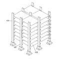
- FIG. 1 and 2 show a support column 3 on which a mounting table 4 is specifically formed.
- the mounting table 4 it is preferable to form the mounting table 4 on the support column because the bridge member 5 can be easily mounted and the bridge can be easily bridged.
- a known fixing method or fixture may be used in combination with the mounting table 4.
- the bridge member 5 is fixed to the mounting table 4 through a known fixing method or a fixture, the bridge member, the honeycomb, and the like mounted on the mounting table can be stabilized, and a torsional stress or the like on the column This is preferable because the burden can be reduced and the strength of the column can be increased.
- FIG. 2 is a diagram schematically showing a method of firing a ceramic honeycomb formed body using the shelf assembly in the present embodiment.
- the thickness of the column can be appropriately changed depending on the shape of the column, the weight of the object to be fired, the weight and dimensions of the shelf board to be used, etc., but usually 3 to 10 mm.
- the thickness is preferably about 3 to 5 mm.
- a method for manufacturing a support containing silicon carbide and silicon nitride will be described as a method for manufacturing the support.
- a predetermined amount of SiC powder, Si powder, a binder, water, or an organic solvent is kneaded and cast to obtain a molded body having a desired shape.
- this molded body is dried at 90 ° C. and then fired in a nitrogen atmosphere to produce Si 3 N 4 by a reaction between Si and nitrogen, thereby producing a composite material of silicon carbide and silicon nitride.
- a method can be mentioned.
- the bridge member 5 in the present embodiment is a horizontal support member that constitutes a part of a beam-structured shelf assembly.
- the honeycomb formed body is placed on the latter bridge member and fired. Therefore, since the honeycomb formed body is placed on the bridge member in the beam-structured shelf, it is desirable that the bridge member is bridged in the horizontal direction.
- this horizontal direction does not require a horizontal state in a strict sense, and it is sufficient if the horizontal direction has a level enough to stably place the article to be fired.
- the bridge member be arranged apart from the adjacent bridge member. This is because the adjacent bridge members are arranged without being separated from each other, so that no gas is trapped in the honeycomb structure, the contact area can be suppressed, and the effects of the present application can be achieved.
- the column 3 is provided with a mounting table 4 that supports the bridge member 5 (first bridging member 5 a), and the bridge member 5 (second bridging member 5 b) on the mounting table 4. Is placed or fixed (via a fixture or the like). Further, the tochi 107 is placed on the bridge member 5 (second bridging member), and the honeycomb formed body 100 is placed on the tochi 107 described above. As described above, when the ceramic honeycomb formed body is fired by using the shelf assembly in the present embodiment, the ceramic honeycomb formed body 100 and the shelf board are connected between the ceramic honeycomb formed body 100 and the shelf board (or via Tochi. Gas) is not trapped in the fired product.
- the contact area of the bottom surface of the honeycomb formed body is reduced, and the dimensional deformation of the honeycomb formed body can be controlled to be small by reducing the frictional resistance when shrinking during firing. Furthermore, the packing efficiency of the objects to be fired can be improved.
- arranged apart from adjacent bridge members means a relationship between a bridging member arranged on the same horizontal plane and a bridging member arranged on the same horizontal plane.
- “Disposed” means at least so as not to contact. This is because by arranging the bridging members arranged on the same horizontal plane so as not to contact each other at least, gas does not accumulate in the honeycomb structure and the effects of the present application can be achieved.
- the “adjacent bridge member” excludes a bridge member that is bridged by a column and a bridge member that is on the bridge member that is bridged by the column. This is because the bridging member that is bridged to the column and the bridging member that is on the bridge member bridged to the column are structurally in contact with each other and are not separated from each other.
- the above-described horizontal plane does not require a horizontal plane state in a strict sense, and may be level enough to stably place the article to be fired.
- the bridge member that is spaced apart from the “adjacent bridge member” is a relationship between the bridge member 5 b that is arranged on the same horizontal plane and the bridge member 5 b that is arranged on the same horizontal plane.
- the relationship between the bridging member 5a and the bridging member 5b is excluded.
- the bridge member of the present embodiment is the same for both (1) the bridge member bridged to the column and (2) the bridge member further bridged to the bridge member bridged to the column. It can be composed of shape, material, etc. However, it is preferable that the bridge member is composed of a first bridge member that is bridged on a support column and a second bridge member that is bridged on the first bridge member, and the first bridge member is a flat plate member.
- the second bridge member is configured as a rectangular column member made of a rectangular column member, and the honeycomb body is placed on the second bridge member and fired. The first bridge member is used as a member to be bridged on the support column, and the second bridge member is used by being further bridged on the first bridge member.
- the honeycomb formed body is placed on the second bridge member and fired.
- the reason why the bridging member is configured as a separate member in this manner is that it is easier to achieve the effects of the present application when the bridging member is made of a configuration and material corresponding to each role.
- it is desirable that the first bridging member and the second bridging member are also bridged in the horizontal direction, but this horizontal direction does not require a horizontal state in a strict sense, and the product to be fired is stabilized. It is sufficient if there is a level of horizontalness.
- the first bridge member 5 a is a member for bridging the support column 3 and constitutes a part of the shelf assembly.
- the shape of the first bridge member 5a include a prismatic member having a prismatic shape, a flat plate member, and the like. However, a flat member is more preferable.
- a second bridge member described later can be easily placed on the first bridge member. This is because it is easy to place the components stably.
- the shape of the second bridge member is not limited to such a shape. For example, even if the second bridge member has a cylindrical shape, the surface on which the second bridge member or the like is to be placed is processed to be easily placed. Is included in the shape of the first bridge member in the present embodiment.
- the cross-sectional shape of the first bridge member for example, a solid or hollow triangular columnar or quadrangular columnar column can be cited. It is because it can comprise as a lightweight member by shape
- the material of the first bridge member is composed of a refractory material having high compressive strength and high heat resistance.
- a refractory material having high compressive strength and high heat resistance examples thereof include silicon-impregnated silicon carbide refractories.
- the first bridge member is made of a composite material of silicon carbide and silicon nitride.
- a prismatic member is formed from a composite material of silicon carbide and silicon nitride, it can further withstand the load of the object to be fired, and can withstand high-temperature firing in a firing furnace. To preferred.
- the cross-sectional shape includes, for example, 120 ⁇ 20 mm / thickness 5 mm, 160 ⁇ 30 mm / thickness 5 mm, 200 ⁇ 50 mm / thickness 5 mm, etc., but is not limited to these sizes. If the structural strength of about 5 times the generated stress can be secured, there is no particular problem, and it can be used as a bridging member of the present application.
- the size of the first bridge member is not particularly limited, but a suitably wide one is preferable. This is because the second bridge member and the honeycomb formed body can be easily placed on the first bridge member and can be easily stabilized.
- the through-hole is formed and the second bridge member is penetrated, for example, when a fixing tool having a recess or the like corresponding to the diameter of the bridge member is used, rattling in the through-hole is reduced. Therefore, it is possible to use a prism member thinner than the through-hole diameter, which is preferable. It should be noted that it is desirable to select a suitable size for the first bridge member according to needs such as the weight of the honeycomb to be placed.
- the column and the mounting base of the bridge member are in contact with each other over the entire surface. This is preferable because the load can be dispersed and supported. Moreover, even when a torsional stress is applied to the support column, the mounting table of the first bridge member rotates along the cylindrical surface to absorb the torsion, so that the support column can be prevented from being damaged by a crack.
- the first bridge member is inserted into a through hole formed in the support column, and the first bridge member is mounted on the upper surface of the mounting table formed on the support column. It is preferable to mount and assemble (assemble) at least two first bridge members in parallel between the columns. If necessary, the first bridge member may be fixed to the upper surface of the mounting table by a known fixture or fixing method.
- a mounting base (a protruding portion of a support column) made of a columnar protrusion may be provided at a place where the first bridging member is placed, and a hole may be formed in the first bridging member to be inserted and fixed. A hole can be made in the first bridging member and the column, and a cylindrical pin can be inserted and fixed.
- the second bridging member can be attached to the first bridging member by providing semicircular protrusions on both sides of the large bridging member to prevent the second bridging member from shifting.
- a hole can be made in the first bridging member and the second bridging member, and a cylindrical pin can be inserted and fixed.
- Second bridge member As shown in FIG. 1, the second bridge member 5 b is a member for bridging on the first bridge members 5 a facing each other, and constitutes a part of the shelf assembly.
- the honeycomb formed body is placed on the second bridge member and fired.
- Examples of the shape of the second bridge member include a prismatic member having a prismatic shape, a flat plate member, and the like.
- a prism member having a prismatic shape is more preferable. This is because, when the second bridge member is composed of a prismatic member, the surface on which the torch, the honeycomb formed body, etc. are placed is horizontal and easy to place stably. In addition, if it is not horizontal, the load applied to the honeycomb mounting surface is not uniform, and the honeycomb is likely to be deformed, or harmful effects such as cracks during firing are likely to occur, and the characteristics of the honeycomb are also impaired. Because. The above-mentioned horizontal does not require a horizontal state in a strict sense, and it is sufficient if the horizontality is sufficient to stably place a torch, a honeycomb formed body, and the like.
- the cross-sectional shape of the second bridge member for example, a solid or hollow triangular columnar or quadrangular columnar column can be cited. It is because it can comprise as a lightweight member by shape
- the material of the second bridge member is preferably composed of a refractory having high compressive strength and high heat resistance.
- a refractory having high compressive strength and high heat resistance For example, silicon-impregnated silicon carbide refractories can be used.
- the second bridge member is made of a composite material of silicon carbide and silicon nitride.
- a prismatic member is formed from a composite material of silicon carbide and silicon nitride, it can further withstand the load of the object to be fired, and can withstand high-temperature firing in a firing furnace. To preferred.
- the cross-sectional shape of the bridge member may be 20 ⁇ 20 mm / thickness 5 mm, 30 ⁇ 30 mm / thickness 5 mm, 40 ⁇ 50 mm / thickness 5 mm, etc.
- a structural strength of about 5 times the generated stress can be ensured without being limited to a particular size, and it can be used as a bridging member of the present application.
- nitride-bonded SiC made by NGK Adrek or Saint-Gobain can be used.
- the size of the second bridge member is not particularly limited, but is preferably narrower than the size of the first bridge member but appropriately wide. If the width is too wide, the number of honeycomb molded bodies that can be mounted is reduced, and further, a gap between the second bridge member and the adjacent second bridge member cannot be formed, and gas tends to be trapped in the honeycomb molded body. This is because it becomes difficult to achieve the effects of the present application. Further, if the width is excessively narrow, it is difficult to stably place the honeycomb formed body. Further, the weight of the honeycomb formed body is locally concentrated on the contact surface with the second bridge member (or torch), and the like. This is because it may cause adverse effects. In addition, it is preferable to select a suitable size according to needs such as the weight of the honeycomb to be placed.
- the contact area between the second bridge member and the bottom surface of the honeycomb molded body is preferably 20 to 70% of the bottom area of the honeycomb molded body. It is preferable for the contact area to be within such a desired range because no gas is trapped in the honeycomb molded body, abnormal combustion of the molded body can be controlled, and the crack generation rate can be suppressed. That is, since the gap can be reliably formed between the second bridge member and the second bridge member, the effect of the present application can be achieved.
- the second bridge members are arranged so that the distance between adjacent second bridge members is in the range of 10 to 150 mm.
- the second bridge member may be placed with a predetermined interval.
- two or more prismatic members may be crossed and placed on the two members used as the first bridge member.
- the prism member used in (2) is placed so that an appropriate gap can be formed. This is because, if there is no gap, the honeycomb molded body is filled with gas, and the effects of the present application cannot be achieved.
- the gap is large, the honeycomb formed body cannot be stably placed, and its own weight resulting from the inclination is concentrated locally, which may cause problems such as deformation of the honeycomb formed body.
- the shelf structure of the beam structure in the present embodiment includes at least the above-described support, a bridge member that is bridged to the support, and a bridge member that is further bridged on the bridge member. That is, a beam-structured shelf is configured by alternately stacking a pillar, a bridge member bridged by the pillar, and a bridge member further bridged on the bridge member.
- first bridge members 5a are arranged across the four levels in the length direction of the shelf assembly between the top of the column and the lowest part of the column.
- the second bridge member 5b is bridged and placed so as to bridge the pair of first bridge members 5a.
- the second bridge member 5b is mounted in a total of 24 pieces of 6 ⁇ 4 steps per step. Then, after placing the honeycomb formed body (or the honeycomb formed body through the torch) on the second bridge member that has been mounted, another column is set up at the four corners of the column in the same manner as described above. And the process of placing another first bridge member on the top of the column is repeated to complete the shelf assembly.
- pillar is not restricted to a 1st bridge member, If it can use as a beam and the durability which can respond to a calcination of a honeycomb is obtained, it will be 1st bridge.
- a widely known member may be used instead of the member.
- the number of columns used and the number of prism members used can be changed as appropriate depending on the shape of the shelf.
- the thickness of the prismatic member can be reduced. Specifically, the thickness can be reduced to about 25 to 50 cm ⁇ 25 to 50 cm ⁇ 5 mm (thickness).
- a mounting base for the first bridge member, a fixture used in combination with the mounting base, etc. are not indispensable, but are preferably used because the first bridge member can be stably mounted and fixed. That is, the mounting member and the fixing member are in contact with the above-described prism member, support the load by dispersing, and the mounting table, the fixing tool, etc. become a so-called reinforcing member even when a torsional stress is applied to the column. It is possible to prevent damage to the support due to cracks.
- the mounting table, the fixture used in combination with the mounting table, etc. may be configured separately from the column, and may be installed, for example, in an elliptical or circular through-hole formed in the column. Moreover, you may form in a support
- Tochi is a member to prevent defects and malfunctions such as chipping of the lower end outer periphery of the ceramic honeycomb that is a fired body, or cutting of the end face of the ceramic honeycomb, cracking of cells, rib cutting, etc. It is generally used and is preferably used also when firing the honeycomb formed body in the present embodiment.
- tochi is also called a setter and refers to a so-called underlay-like member that supports the fired product on the cross-linking member.
- the tochi (tochi) is used between the honeycomb formed body and the first bridge member (square column member) when the honeycomb formed body is fired, and is configured as a plate-like member.
- the ceramic honeycomb structure is manufactured by firing a honeycomb formed body obtained by forming a green body in an upright state in a firing furnace with one end face down. During the firing, the honeycomb formed body contracts in the cell length direction and the direction orthogonal to the cell length direction, and if the honeycomb formed body is placed directly on the first bridge member, the first bridge is formed. Due to the frictional resistance between the member and the honeycomb formed body and the adhesion of the bridge member on the end face of the honeycomb formed body, the above-described adverse effects may occur. Therefore, in order to prevent such defects and defects, it is preferable to use Tochi (Tochi).
- Tochi Tochi
- This tochi (tochi) is basically a sintered torch with no firing shrinkage, or an unfired torch with the same firing shrinkage made of the same material as the material to be fired.
- a certain “raw tochi / co-tochi” is common, but a tochi (tochi) suitably used in the present embodiment is “raw tochi / co-tochi”. Costs since the torch can be used repeatedly if “baked tochi” is used instead of unfired “raw tochi / co-tochi” made of the same material as the material to be fired and having the same firing shrinkage. However, since the “baked torch” becomes a so-called lid when the honeycomb formed body is fired, the gas generated from the binder cannot be completely removed and may be trapped in the honeycomb. Accordingly, since the effect of the present application cannot be sufficiently achieved, it is preferable to use “raw tochi / co-tochi”.
- the cost can be increased because it can be used only once, but the occurrence of ribs, cells, etc. in the ceramic honeycomb is suppressed, so that the quality can be improved. Further, since the material is made of the same material as the honeycomb, the contact surface does not become a so-called lid of the honeycomb, and gas can be prevented from being trapped in the honeycomb.
- the calcination furnace trolley in the present embodiment is a pedestal (trolley) used by placing a honeycomb formed body, which is a product to be fired, on a beam-structured shelf on the calcination furnace trolley and moving the kiln in a predetermined direction. That is.
- the carriage for the firing furnace is formed so that a moving means can be attached.
- the present invention is not limited to such a baking table, and can be used as a baking table of the present application as long as it is a known baking table and can mount the beam structure of the present application.
- Ceramic honeycomb formed body The ceramic honeycomb formed body fired by the honeycomb formed body firing method of the present embodiment is a ceramic honeycomb formed body having a large number of cells arranged in the axial direction.
- the honeycomb formed body of the present embodiment is prepared by kneading a predetermined forming raw material to prepare a kneaded material, forming the prepared kneaded material to produce a honeycomb-shaped formed body, and drying it to form a honeycomb formed body Can be obtained by firing the honeycomb formed body obtained.
- the method of kneading the forming raw material to prepare the kneaded material is not particularly limited, and examples thereof include a method using a kneader, a vacuum kneader or the like.
- the predetermined forming raw material can be appropriately selected according to a desired material.
- the method for producing the honeycomb-shaped molded body is not particularly limited, and a conventionally known molding method such as extrusion molding, injection molding, or press molding can be used.
- a preferable example is a method of extruding the clay prepared as described above using a die having a desired outer peripheral wall thickness, partition wall thickness, and cell density.
- the method is as follows. In other words, the supply of soil to the place to be thinned is reduced by changing the diameter and arrangement of the back hole of the base and the shape of the press plate used to form the outer peripheral wall, thereby forming a specific position thinly. Make a difference in the outer wall thickness.
- the drying method is not particularly limited, and conventionally known drying methods such as hot air drying, microwave drying, dielectric drying, vacuum drying, vacuum drying, freeze drying and the like can be used. Especially, the drying method which combined hot air drying, microwave drying, or dielectric drying is preferable at the point which can dry the whole molded object rapidly and uniformly.
- the drying conditions can be appropriately selected according to the shape, material and the like of the honeycomb formed body.
- the honeycomb formed body dried by the above-described method can be fired in a firing furnace to obtain the honeycomb structure of the present embodiment.
- the firing furnace and firing conditions can be appropriately selected according to the shape, material, and the like of the honeycomb formed body.
- organic substances such as a binder may be burned and removed by temporary firing.
- the material of the honeycomb formed body in the present embodiment is silicon-carbonized formed from silicon carbide (SiC), silicon carbide (SiC) as an aggregate and silicon (Si) as a binder from the viewpoint of strength and heat resistance.
- silicon carbide (SiC) as an aggregate
- Si silicon
- silicon carbide-cordierite-based composite materials lithium aluminum silicate, aluminum titanate, and Fe-Cr-Al based metals
- silicon carbide (SiC) or a silicon-silicon carbide based composite material are preferable.
- the same material as the honeycomb formed body can be used as the filler used for the plugging.
- the filler for plugging with a filler, for example, cells that are not plugged are masked, so that the end face of the honeycomb segment is immersed in a slurry-like filler and filled into open (unmasked) cells. This can be done.
- the filling of the filler may be performed before or after firing after forming the honeycomb, but it is preferable to perform the filling before firing because the firing step is completed once.
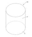
- FIG. 3 is a diagram schematically showing the honeycomb formed body, in which a large number of cells arranged in the axial direction are omitted.
- honeycomb formed body Preparation of honeycomb formed body (raw honeycomb structure) before firing: As a raw material, cordierite-forming raw materials mainly composed of talc, kaolin, and alumina are mixed with water and binder, and then the mixed raw materials are extruded into a cylindrical shape by a kneader, and then extruded. Was extruded to obtain a raw honeycomb structure (honeycomb molded body) having a large number of cells of ⁇ 320 mm ⁇ 300 mmL arranged in the axial direction.
- honeycomb compact (raw honeycomb structure): The honeycomb formed body (raw honeycomb structure) before firing was prepared in the same manner as the honeycomb formed body (raw honeycomb structure) obtained in [1-1] above.
- the pillars and prismatic members of Examples 7 to 11 were molded in a desired shape by kneading and molding a predetermined amount of C powder, SiC powder, Si 3 N 4 , binder, water or organic solvent, as described above. After the body was obtained, the compact was prepared by placing the compact in an inert gas or vacuum under reduced pressure in a metal Si atmosphere and impregnating the compact with metal Si.
- the green honeycomb molded body is dried, the green honeycomb molded body is placed on the prismatic member so as to have a desired contact area using the beam structure shelves in Examples 7 to 11 and Comparative Example 2. Then, the fired honeycomb bodies of Examples 7 to 11 and Comparative Example 2 were obtained. The results are shown in Table 2. In Comparative Example 2, as described above, “the contact area between the prism and the honeycomb formed body” shown in Table 2 is read as “the contact area between the shelf board and the honeycomb formed body”.
- Example 1 As shown in Table 1, the honeycomb formed body of Example 1 was obtained by forming a shelf with a spacing of 10 mm between the prisms and placing the honeycomb formed body on the shelf and firing it. . In the honeycomb molded body of Example 1, the temperature difference inside and outside the molded body was 65 ° C. and the crack generation rate was 1.5%, but this is not until the characteristics of the honeycomb molded body are greatly impaired. Results were obtained.
- the honeycomb molded bodies of Examples 2 to 6 were shelved with the intervals between the prisms being 30 mm, 60 mm, 90 mm, 120 mm, and 150 mm, respectively.
- the temperature difference between the inside and outside of the molded body of Example 2 was 54 ° C.
- the temperature difference between the inside and outside the molded body of Example 3 was 54 ° C.
- the temperature difference between the inside and outside of the molded body of Example 4 was 52 ° C.
- the difference is 48 ° C.
- the temperature difference between the inside and outside of the molded body of Example 6 is 48 ° C.
- the temperature difference between the inside and outside the molded body can be suppressed within a suitable range, and the occurrence rate of each crack is also 0%. It was.
- the honeycomb molded body of Comparative Example 1 since the shelf plate on which the honeycomb molded body is placed is a flat plate, there is no space between the prisms as shown in the above-described embodiments. Therefore, the temperature difference inside and outside the molded body was 95 ° C., and the crack generation rate was 3.2%, and it was proved as a result that it could not withstand the use that greatly deteriorated the characteristics of the honeycomb molded body.
- the contact area between the prism and the honeycomb molded body as shown in each of the above embodiments cannot be adjusted. That is, in Comparative Example 1, the contact area between the shelf board and the honeycomb molded body is 100%, resulting in a dimensional deformation of 1.5 mm, which cannot be used to greatly impair the characteristics of the honeycomb molded body. It was proved as a result.
- a method for firing a honeycomb formed body of the present invention is a method for firing a ceramic honeycomb formed body using a firing furnace carriage composed of a beam-structured shelf composed of columns and bridge members, the ceramic honeycomb formed body
- a firing furnace carriage composed of a beam-structured shelf composed of columns and bridge members
- the ceramic honeycomb formed body By placing and firing on the prismatic member, there is a gap between the prismatic member and the prismatic member, so the decomposition gas generated inside the honeycomb molded body during firing escapes from the bottom of the honeycomb molded body and suddenly Generation of defects such as cracks due to heat generation can be suppressed, dimensional deformation of the honeycomb formed body can be reduced, and the honeycomb formed body can be suitably used as a firing method for improving packing efficiency.
Landscapes
- Engineering & Computer Science (AREA)
- Chemical & Material Sciences (AREA)
- Ceramic Engineering (AREA)
- Manufacturing & Machinery (AREA)
- Materials Engineering (AREA)
- Structural Engineering (AREA)
- Organic Chemistry (AREA)
- Inorganic Chemistry (AREA)
- Mechanical Engineering (AREA)
- General Engineering & Computer Science (AREA)
- Furnace Charging Or Discharging (AREA)
- Ceramic Products (AREA)
Abstract
La présente invention concerne un procédé pour fritter un comprimé céramique en nid d'abeille qui comporte de nombreuses cellules juxtaposées dans la direction axiale, en utilisant un chariot pour un four de frittage d'une ossature d'une structure de poutre. Dans le procédé de frittage de comprimé en nid d'abeille pour fritter un comprimé en nid d'abeille, l'ossature (1) de la structure de poutre comprend des montants (3), des éléments de poutre principale (5a) qui relient les montants, et des éléments de poutre principale (5b) qui relient en outre les éléments de poutre principale (5a), les éléments de poutre principale (5b) qui relient les éléments de poutre principale étant agencés de manière à être espacés des éléments adjacents de poutre principale, et le corps en nid d'abeille étant placé par-dessus les éléments de poutre principale. Des espaces libres sont laissés entre des éléments de prismes de sorte que les gaz décomposés au cours de l'opération de frittage peuvent être empêchés de quitter la partie inférieure du comprimé en nid d'abeille, pour ainsi supprimer les défauts tels que des fissures, qui pourraient autrement être entraînés abruptement par une production de chaleur. La déformation de taille du comprimé en nid d'abeille peut être réduite pour ainsi perfectionner le rendement de compactage.
Applications Claiming Priority (2)
| Application Number | Priority Date | Filing Date | Title |
|---|---|---|---|
| JP2008013750 | 2008-01-24 | ||
| JP2008-013750 | 2008-01-24 |
Publications (1)
| Publication Number | Publication Date |
|---|---|
| WO2009093690A1 true WO2009093690A1 (fr) | 2009-07-30 |
Family
ID=40901193
Family Applications (1)
| Application Number | Title | Priority Date | Filing Date |
|---|---|---|---|
| PCT/JP2009/051079 Ceased WO2009093690A1 (fr) | 2008-01-24 | 2009-01-23 | Procédé de frittage pour comprimé en nid d'abeille |
Country Status (1)
| Country | Link |
|---|---|
| WO (1) | WO2009093690A1 (fr) |
Cited By (2)
| Publication number | Priority date | Publication date | Assignee | Title |
|---|---|---|---|---|
| JP2010127591A (ja) * | 2008-12-01 | 2010-06-10 | Ngk Insulators Ltd | 焼成用棚組 |
| JP2019158221A (ja) * | 2018-03-13 | 2019-09-19 | 三浦工業株式会社 | 食品機械用棚板 |
Citations (7)
| Publication number | Priority date | Publication date | Assignee | Title |
|---|---|---|---|---|
| JPS62202870A (ja) * | 1986-02-20 | 1987-09-07 | 日本碍子株式会社 | セラミツクスハニカム構造体の焼成方法 |
| JPS63210593A (ja) * | 1987-02-27 | 1988-09-01 | 日本碍子株式会社 | セラミツクハニカム構造体の焼成法 |
| JP2004301402A (ja) * | 2003-03-31 | 2004-10-28 | Ngk Insulators Ltd | 熱処理炉 |
| JP2005082451A (ja) * | 2003-09-09 | 2005-03-31 | Ngk Insulators Ltd | 窒化珪素結合SiC耐火物及びその製造方法 |
| JP2005207646A (ja) * | 2004-01-21 | 2005-08-04 | Chugai Ro Co Ltd | 被焼成物の送り装置及び焼成炉 |
| JP2007010235A (ja) * | 2005-06-30 | 2007-01-18 | Asahi Glass Co Ltd | セラミックス熱処理用治具 |
| JP2008120653A (ja) * | 2006-11-15 | 2008-05-29 | Denso Corp | セラミックハニカム成形体の焼成用載置台 |
-
2009
- 2009-01-23 WO PCT/JP2009/051079 patent/WO2009093690A1/fr not_active Ceased
Patent Citations (7)
| Publication number | Priority date | Publication date | Assignee | Title |
|---|---|---|---|---|
| JPS62202870A (ja) * | 1986-02-20 | 1987-09-07 | 日本碍子株式会社 | セラミツクスハニカム構造体の焼成方法 |
| JPS63210593A (ja) * | 1987-02-27 | 1988-09-01 | 日本碍子株式会社 | セラミツクハニカム構造体の焼成法 |
| JP2004301402A (ja) * | 2003-03-31 | 2004-10-28 | Ngk Insulators Ltd | 熱処理炉 |
| JP2005082451A (ja) * | 2003-09-09 | 2005-03-31 | Ngk Insulators Ltd | 窒化珪素結合SiC耐火物及びその製造方法 |
| JP2005207646A (ja) * | 2004-01-21 | 2005-08-04 | Chugai Ro Co Ltd | 被焼成物の送り装置及び焼成炉 |
| JP2007010235A (ja) * | 2005-06-30 | 2007-01-18 | Asahi Glass Co Ltd | セラミックス熱処理用治具 |
| JP2008120653A (ja) * | 2006-11-15 | 2008-05-29 | Denso Corp | セラミックハニカム成形体の焼成用載置台 |
Cited By (2)
| Publication number | Priority date | Publication date | Assignee | Title |
|---|---|---|---|---|
| JP2010127591A (ja) * | 2008-12-01 | 2010-06-10 | Ngk Insulators Ltd | 焼成用棚組 |
| JP2019158221A (ja) * | 2018-03-13 | 2019-09-19 | 三浦工業株式会社 | 食品機械用棚板 |
Similar Documents
| Publication | Publication Date | Title |
|---|---|---|
| EP2251628B1 (fr) | Plaque outil de four pour la cuisson de céramique | |
| EP1647790B1 (fr) | Méthode de fabrication de corps en céramique poreuse | |
| US7892623B2 (en) | Honeycomb structured body, manufacturing device of honeycomb structured body and manufacturing method of honeycomb structured body | |
| US20080236724A1 (en) | Method for manufacturing honeycomb structure | |
| US10493394B2 (en) | Porous material, method for manufacturing porous material, and honeycomb structure | |
| JP7488875B2 (ja) | 加熱炉 | |
| US20080254271A1 (en) | Si-SiC BASED FIRED BODY AND METHOD FOR MANUFACTURING THE SAME | |
| WO2011040145A1 (fr) | Structure de nid d'abeilles et procédé pour sa fabrication | |
| US20100116427A1 (en) | Honeycomb segment-forming die and method for manufacturing honeycomb structure | |
| US11066336B2 (en) | Honeycomb structure | |
| US20060240212A1 (en) | Honeycomb structure | |
| WO2009093691A1 (fr) | Procédé de frittage pour comprimé en nid d'abeille | |
| JP2012001426A (ja) | セラミクスハニカム焼成体の製造方法 | |
| US20150252702A1 (en) | Honeycomb structure | |
| US20180257999A1 (en) | Honeycomb structure | |
| JP6113272B2 (ja) | 棚システム用のセラミックの板 | |
| JP2005219977A (ja) | セラミックスハニカム焼成用トチ及びセラミックスハニカムの焼成方法 | |
| JP5478896B2 (ja) | ハニカムセグメント接合体の製造方法 | |
| EP2233453B1 (fr) | Structure en nid d'abeille | |
| US20190030752A1 (en) | Manufacturing method of honeycomb structure | |
| JP2008120653A (ja) | セラミックハニカム成形体の焼成用載置台 | |
| JP6329462B2 (ja) | セラミック構造体の製造方法 | |
| WO2025063034A1 (fr) | Structure en nid d'abeille en céramique à base de cordiérite et son procédé de production | |
| JP7803894B2 (ja) | 焼成体の製造方法 | |
| JP2008273810A (ja) | ハニカム構造体の製造方法 |
Legal Events
| Date | Code | Title | Description |
|---|---|---|---|
| 121 | Ep: the epo has been informed by wipo that ep was designated in this application |
Ref document number: 09704704 Country of ref document: EP Kind code of ref document: A1 |
|
| NENP | Non-entry into the national phase |
Ref country code: DE |
|
| 122 | Ep: pct application non-entry in european phase |
Ref document number: 09704704 Country of ref document: EP Kind code of ref document: A1 |
|
| NENP | Non-entry into the national phase |
Ref country code: JP |