WO2009093843A2 - 바인더 수지에 카본입자가 분산되어 있는 코팅층을 가지는 연료전지용 금속분리판 및 그 제조방법 - Google Patents
바인더 수지에 카본입자가 분산되어 있는 코팅층을 가지는 연료전지용 금속분리판 및 그 제조방법 Download PDFInfo
- Publication number
- WO2009093843A2 WO2009093843A2 PCT/KR2009/000314 KR2009000314W WO2009093843A2 WO 2009093843 A2 WO2009093843 A2 WO 2009093843A2 KR 2009000314 W KR2009000314 W KR 2009000314W WO 2009093843 A2 WO2009093843 A2 WO 2009093843A2
- Authority
- WO
- WIPO (PCT)
- Prior art keywords
- fuel cell
- plate
- metal
- metal separator
- carbon particles
- Prior art date
- Legal status (The legal status is an assumption and is not a legal conclusion. Google has not performed a legal analysis and makes no representation as to the accuracy of the status listed.)
- Ceased
Links
Images





Classifications
-
- H—ELECTRICITY
- H01—ELECTRIC ELEMENTS
- H01M—PROCESSES OR MEANS, e.g. BATTERIES, FOR THE DIRECT CONVERSION OF CHEMICAL ENERGY INTO ELECTRICAL ENERGY
- H01M8/00—Fuel cells; Manufacture thereof
- H01M8/02—Details
- H01M8/0202—Collectors; Separators, e.g. bipolar separators; Interconnectors
- H01M8/0204—Non-porous and characterised by the material
- H01M8/0206—Metals or alloys
-
- A—HUMAN NECESSITIES
- A63—SPORTS; GAMES; AMUSEMENTS
- A63B—APPARATUS FOR PHYSICAL TRAINING, GYMNASTICS, SWIMMING, CLIMBING, OR FENCING; BALL GAMES; TRAINING EQUIPMENT
- A63B69/00—Training appliances or apparatus for special sports
- A63B69/36—Training appliances or apparatus for special sports for golf
- A63B69/3661—Mats for golf practice, e.g. mats having a simulated turf, a practice tee or a green area
-
- A—HUMAN NECESSITIES
- A63—SPORTS; GAMES; AMUSEMENTS
- A63B—APPARATUS FOR PHYSICAL TRAINING, GYMNASTICS, SWIMMING, CLIMBING, OR FENCING; BALL GAMES; TRAINING EQUIPMENT
- A63B69/00—Training appliances or apparatus for special sports
- A63B69/36—Training appliances or apparatus for special sports for golf
- A63B69/3621—Contacting or non-contacting mechanical means for guiding the swing
-
- C—CHEMISTRY; METALLURGY
- C23—COATING METALLIC MATERIAL; COATING MATERIAL WITH METALLIC MATERIAL; CHEMICAL SURFACE TREATMENT; DIFFUSION TREATMENT OF METALLIC MATERIAL; COATING BY VACUUM EVAPORATION, BY SPUTTERING, BY ION IMPLANTATION OR BY CHEMICAL VAPOUR DEPOSITION, IN GENERAL; INHIBITING CORROSION OF METALLIC MATERIAL OR INCRUSTATION IN GENERAL
- C23G—CLEANING OR DE-GREASING OF METALLIC MATERIAL BY CHEMICAL METHODS OTHER THAN ELECTROLYSIS
- C23G1/00—Cleaning or pickling metallic material with solutions or molten salts
- C23G1/02—Cleaning or pickling metallic material with solutions or molten salts with acid solutions
- C23G1/08—Iron or steel
- C23G1/085—Iron or steel solutions containing HNO3
-
- H—ELECTRICITY
- H01—ELECTRIC ELEMENTS
- H01M—PROCESSES OR MEANS, e.g. BATTERIES, FOR THE DIRECT CONVERSION OF CHEMICAL ENERGY INTO ELECTRICAL ENERGY
- H01M8/00—Fuel cells; Manufacture thereof
- H01M8/02—Details
- H01M8/0202—Collectors; Separators, e.g. bipolar separators; Interconnectors
- H01M8/0204—Non-porous and characterised by the material
- H01M8/0213—Gas-impermeable carbon-containing materials
-
- H—ELECTRICITY
- H01—ELECTRIC ELEMENTS
- H01M—PROCESSES OR MEANS, e.g. BATTERIES, FOR THE DIRECT CONVERSION OF CHEMICAL ENERGY INTO ELECTRICAL ENERGY
- H01M8/00—Fuel cells; Manufacture thereof
- H01M8/02—Details
- H01M8/0202—Collectors; Separators, e.g. bipolar separators; Interconnectors
- H01M8/0204—Non-porous and characterised by the material
- H01M8/0221—Organic resins; Organic polymers
-
- H—ELECTRICITY
- H01—ELECTRIC ELEMENTS
- H01M—PROCESSES OR MEANS, e.g. BATTERIES, FOR THE DIRECT CONVERSION OF CHEMICAL ENERGY INTO ELECTRICAL ENERGY
- H01M8/00—Fuel cells; Manufacture thereof
- H01M8/02—Details
- H01M8/0202—Collectors; Separators, e.g. bipolar separators; Interconnectors
- H01M8/0204—Non-porous and characterised by the material
- H01M8/0223—Composites
- H01M8/0226—Composites in the form of mixtures
-
- H—ELECTRICITY
- H01—ELECTRIC ELEMENTS
- H01M—PROCESSES OR MEANS, e.g. BATTERIES, FOR THE DIRECT CONVERSION OF CHEMICAL ENERGY INTO ELECTRICAL ENERGY
- H01M8/00—Fuel cells; Manufacture thereof
- H01M8/02—Details
- H01M8/0202—Collectors; Separators, e.g. bipolar separators; Interconnectors
- H01M8/0204—Non-porous and characterised by the material
- H01M8/0223—Composites
- H01M8/0228—Composites in the form of layered or coated products
-
- H—ELECTRICITY
- H01—ELECTRIC ELEMENTS
- H01M—PROCESSES OR MEANS, e.g. BATTERIES, FOR THE DIRECT CONVERSION OF CHEMICAL ENERGY INTO ELECTRICAL ENERGY
- H01M8/00—Fuel cells; Manufacture thereof
- H01M8/10—Fuel cells with solid electrolytes
- H01M2008/1095—Fuel cells with polymeric electrolytes
-
- H—ELECTRICITY
- H01—ELECTRIC ELEMENTS
- H01M—PROCESSES OR MEANS, e.g. BATTERIES, FOR THE DIRECT CONVERSION OF CHEMICAL ENERGY INTO ELECTRICAL ENERGY
- H01M8/00—Fuel cells; Manufacture thereof
- H01M8/02—Details
- H01M8/0202—Collectors; Separators, e.g. bipolar separators; Interconnectors
- H01M8/0204—Non-porous and characterised by the material
- H01M8/0206—Metals or alloys
- H01M8/0208—Alloys
- H01M8/021—Alloys based on iron
-
- Y—GENERAL TAGGING OF NEW TECHNOLOGICAL DEVELOPMENTS; GENERAL TAGGING OF CROSS-SECTIONAL TECHNOLOGIES SPANNING OVER SEVERAL SECTIONS OF THE IPC; TECHNICAL SUBJECTS COVERED BY FORMER USPC CROSS-REFERENCE ART COLLECTIONS [XRACs] AND DIGESTS
- Y02—TECHNOLOGIES OR APPLICATIONS FOR MITIGATION OR ADAPTATION AGAINST CLIMATE CHANGE
- Y02E—REDUCTION OF GREENHOUSE GAS [GHG] EMISSIONS, RELATED TO ENERGY GENERATION, TRANSMISSION OR DISTRIBUTION
- Y02E60/00—Enabling technologies; Technologies with a potential or indirect contribution to GHG emissions mitigation
- Y02E60/30—Hydrogen technology
- Y02E60/50—Fuel cells
-
- Y—GENERAL TAGGING OF NEW TECHNOLOGICAL DEVELOPMENTS; GENERAL TAGGING OF CROSS-SECTIONAL TECHNOLOGIES SPANNING OVER SEVERAL SECTIONS OF THE IPC; TECHNICAL SUBJECTS COVERED BY FORMER USPC CROSS-REFERENCE ART COLLECTIONS [XRACs] AND DIGESTS
- Y02—TECHNOLOGIES OR APPLICATIONS FOR MITIGATION OR ADAPTATION AGAINST CLIMATE CHANGE
- Y02P—CLIMATE CHANGE MITIGATION TECHNOLOGIES IN THE PRODUCTION OR PROCESSING OF GOODS
- Y02P70/00—Climate change mitigation technologies in the production process for final industrial or consumer products
- Y02P70/50—Manufacturing or production processes characterised by the final manufactured product
Definitions
- the present invention relates to a metal separator plate for fuel cells and a method of manufacturing the same, and more particularly, to a separator plate of a polymer electrolyte fuel cell (PEMFC), the corrosion current and the contact resistance of the US Department of Energy (DOE) standards (corrosion current is 1 mW / cm 2 or less and a contact resistance of 20 mPa ⁇ cm 2 or less), and a metal separator for a fuel cell which can improve production efficiency in a continuous process and a method for manufacturing the same.
- PEMFC polymer electrolyte fuel cell
- DOE US Department of Energy
- a fuel cell is a power generation device which converts chemical energy into electrical energy generally by oxidizing and reducing hydrogen and oxygen.
- the unit cell of the fuel cell Since the unit cell of the fuel cell has a low output voltage and practicality, it is generally used by stacking several to several hundred unit cells. In this way, when the unit cells are stacked, the electrical connection between the unit cells is made, the reaction gas is separated, and the separator serves as a flow path through which the coolant flows.
- the separator or bipolar plate, together with the membrane-electrode assembly (MEA), is a key part of the fuel cell, and the structural support of the membrane-electrode assembly and the gas diffusion layer (GDL), the collection and transfer of generated current, and the reaction gas. It plays various roles such as transportation and removal, and cooling water transportation for removing reaction heat.
- the material properties of the separator include excellent electrical conductivity, thermal conductivity, gas sealing property, and chemical stability such as corrosion resistance.
- the metal When the metal is applied as the material of the separator, it is possible to reduce the volume and weight of the fuel cell stack by reducing the thickness of the separator and to manufacture by stamping, thereby securing mass productivity.
- stainless steel As the metal material for the fuel cell separator, stainless steel, aluminum alloy, and carbon steel sheet may be used.
- the passivation film formed on the surface may affect the electrical conductivity, and the fuel cell may be used for a long time in consideration of the high temperature and high humidity conditions.
- the electrical conductivity may gradually decrease, and further, a problem may occur such that the corrosion prevents the separator from performing its function.
- Another method to increase the electrical conductivity and corrosion resistance of the fuel cell separator plate of the metal material is a method of plasma coating or physical vapor deposition (PVD) on the surface of the steel sheet of the metal material, which is a method of improving the electrical conductivity and corrosion resistance Since a separate space called a chamber is required, it is difficult to produce a separator plate in a continuous process, and thus there is a problem in that the production efficiency is reduced.
- PVD physical vapor deposition
- the problem to be solved by the present invention is to maintain excellent electrical conductivity and corrosion resistance without other side effects, even if used for a long time in the operating environment, such as the initial vibration as well as automobile, fuel that can have a high production efficiency as a continuous production process is possible It is to provide a method for producing a battery metal separator plate.
- Another problem to be solved by the present invention is to provide a fuel cell metal separator produced by the manufacturing method proposed in the present invention.
- a method of manufacturing a metal separator plate for a fuel cell including: (a) preparing a base metal plate; (b) pickling the surface of the metal plate; (c) coating a composition comprising a binder resin, carbon particles, and a solvent on the surface of the pickled metal plate; And (d) drying the metal plate coated with the composition on the surface at a temperature below the thermal decomposition temperature of the binder resin and above the boiling point of the solvent to form a coating layer in which carbon particles are dispersed in a binder resin matrix on the surface of the metal plate. And a step, wherein the processes are performed in a continuous process.
- Metal separator plate for fuel cells according to the present invention for solving the other problem is a metal plate; And a coating layer formed on the surface of the metal plate and having carbon particles dispersed throughout the volume of the matrix of the binder resin.
- the manufacturing method of the metal separator plate for fuel cells according to the present invention even if used for a long time in the operating environment as well as the initial stage of vibration as well as the DOE standard (corrosion current 1 ⁇ A / cm2 or less, without other side effects such as powdering phenomenon, Excellent electrical conductivity and corrosion resistance satisfying the contact resistance of 20 mPa ⁇ cm 2 or less can be maintained, and the continuous production process is possible, and thus, high production efficiency can be obtained.
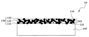
- FIG. 1 is a cross-sectional view showing a metal separator plate for a fuel cell according to the present invention.
- FIG. 2 is a graph showing the results of measuring the surface of the coating layer using AFM (atomic force morphology, SEIKO SPA400) measuring equipment after forming a coating layer using carbon black and graphite alone or a mixture thereof as carbon particles in the polymer resin. For the picture.
- AFM atomic force morphology, SEIKO SPA400
- FIG. 3 is a process flow diagram illustrating a manufacturing process of a metal separator plate for fuel cells according to an embodiment of the present invention.
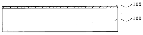
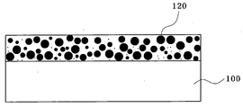
- 4 to 7 are cross-sectional views illustrating a method of manufacturing a stainless steel separator plate for fuel cells according to an embodiment of the present invention.
- FIG. 8 is a view illustrating a contact resistance measuring apparatus for measuring contact resistance of a stainless steel separator plate for fuel cells according to the present invention.
- Example 9 is a graph showing the corrosion resistance measurement results for the stainless 316L separator, graphite separator, the separator prepared in Example 1, and Comparative Example 1.
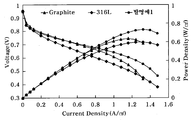
- FIG. 10 is a graph illustrating fuel cell performance evaluation of a stainless steel 316L separator, a graphite separator, and the separator manufactured by Example 1.
- FIG. 10 is a graph illustrating fuel cell performance evaluation of a stainless steel 316L separator, a graphite separator, and the separator manufactured by Example 1.
- FIG. 1 is a cross-sectional view showing a metal separator plate for a fuel cell according to the present invention.
- the metal separator plate 10 for fuel cells includes a metal steel sheet base material 100 and a coating layer 105 formed on the surface of the metal steel plate base material 100.
- the metal sheet base material 100 may be selected from a stainless steel sheet, an aluminum sheet, and a carbon steel sheet, and preferably, a stainless steel sheet is used.
- the stainless steel sheet used is less than 0.08 wt% carbon (C), 16 to 28 wt% chromium (Cr), 0.1 to 20 wt% nickel (Ni), 0.1 Molybdenum (Mo), 0.1 to 5 wt% tungsten (W), 0.1 to 2 wt% tin (Sn), 0.1 to 2 wt% copper and iron (Fe) in the balance.
- the thickness of the metal steel base material 100 is 1t or less, Preferably it is 0.2t or less.
- the coating layer 105 includes a matrix filler 110 of a binder resin and a conductive filler of carbon particles 120 to protect the surface of the metal sheet base material 100 from corrosion. And it serves to transfer the electrical energy generated from the fuel cell.
- the base unit 110 serves as a kind of binder for preventing the carbon particles 120 from being separated from the surface of the metal sheet base material 100 and scattering in the form of powder, that is, powdering. It is made of a polymer resin.
- the polymer resin that can be used for the base unit 110 one or two or more mixtures selected from acrylic resins, phenolic resins, urethane resins, urethane resins, melamine resins, fluorine resins, silicone resins, and epoxy resins are used.
- the polymer resin may also serve as a hardening agent for promoting hardening of the base unit 110.
- the carbon particles 120 are excellent in electrical conductivity and are evenly or unevenly dispersed throughout the entire internal volume of the base portion 110 made of the binder polymer resin.
- the carbon particles 120 are dispersed so that the particles are connected to each other inside the base portion 110 to be electrically connected to the surface of the coating layer 105 from the metal sheet base material 100.
- a portion of the carbon particles 120 is in contact with the surface of the metal sheet base material 100 (carbon particles denoted by reference numeral 121 of FIG. 1), and a portion of the carbon particles 120 is the coating layer 105 It is distributed so as to be exposed or protruded on the surface of (carbon particles represented by the drawing portion 123 of FIG. 1), a portion of the carbon particles 120 and the carbon particles 121 in contact with the surface of the metal sheet base material 100
- the carbon particles 123 existing on the surface of the coating layer 105 are connected to each other (carbon particles represented by reference numeral 122 of FIG. 1) and dispersed in the base unit 110.
- carbon particles 120 one or more selected from carbon black, graphite, and carbon nanotubes may be used.
- the maximum particle size is preferably 1 ⁇ m or less, and when graphite is used, the maximum particle size is preferably 3 ⁇ m or less.
- the content ratio of the polymer binder resin constituting the carbon particles 120 of the coating layer 105 to the base layer 110 is 1: 1 to 6: 1, preferably 2: 1 to 4: 1, based on the weight thereof.
- the reason is that if the content of the polymer resin is too high in the case of less than 1: 1, it is difficult to secure the electrical conductivity of the coating layer 105, and if it exceeds 6: 1, the corrosion resistance is poor and the content of the binder is so small that the powdering phenomenon ( This is because powdering is likely to occur.
- the filling rate of the carbon particles filled in the coating layer 105 directly affects the contact resistance of the entire separator 10, which will be described in detail below.
- 2 (a) to 2 (c) show the surface of the coating layer after forming the coating layer using carbon black and graphite alone or a mixture thereof as carbon particles in the polymer resin (epoxy resin).
- (a) of FIG. 2 is a coating layer formed by using carbon black having a particle diameter of about 0.05 ⁇ m alone.
- the maximum roughness (R max ) of the surface is about 0.5 ⁇ m and the average roughness (Ra) is It was confirmed that it was 0.2 ⁇ m.
- FIG. 2 (b) shows that the coating layer was formed using only graphite having a particle diameter of about 1.0 ⁇ m, and the AFM measurement showed that the maximum roughness of the surface was about 3.0 ⁇ m and the average roughness Ra was about 1.1 ⁇ m.
- FIG. 2 (c) shows a coating layer formed by mixing carbon black having a particle size of about 0.05 ⁇ m and graphite having a particle size of about 1.0 ⁇ m at a ratio of 1: 2.5.
- the maximum roughness of the surface of the AFM measurement result is It was confirmed that it was about 0.26 ⁇ m and the average roughness Ra was about 0.14 ⁇ m.
- the surface roughness is found to be smaller when the mixture is used than when carbon black or graphite is used alone.
- the surface roughness is considered to be relatively high due to coarseness and localized particle aggregation.
- FIG. 2 (c) using a mixture of carbon black and graphite, the surface roughness was relatively lower than that of FIGS. 2 (a) and 2 (b). Since the carbon black, which is a fine particle, is filled in the space between the graphite particles, the inside of the coating layer may be filled, thereby increasing the filling rate of the carbon particles in the coating layer. Since this is prevented it can be seen that the effect of improving the internal conductivity of the coating layer.
- the separator having the coating layer formed according to the present invention the lower the roughness of the coating layer, the lower the interfacial contact resistance with the gas diffusion layer (GDL), thereby reducing the overall contact resistance of the separator. Confirmed.
- the carbon particles used in the coating layer 105 are a mixture of carbon black and graphite alone, and they are mixed with each other at an appropriate ratio. It can be seen that it is possible to increase the filling rate of and to reduce the surface roughness of the coating layer, thereby reducing the overall contact resistance of the separator for fuel cells.
- carbon black having an average particle diameter of 0.03 to 0.1 ⁇ m: graphite having an average particle diameter of 0.5 to 1.0 ⁇ m is used at the same time, and the mixing ratio thereof is mixed so as to be 1: 1 to 1: 3.
- the most optimized filling rate, surface roughness and contact resistance values can be obtained.
- the thickness of the coating layer 105 is 0.1 to 10 ⁇ m, preferably 1.5 to 3.5 ⁇ m, because the corrosion resistance is lowered when the thickness is less than 0.1 ⁇ m. This is because the bonding force to (100) may fall and thus the electrical conductivity may be deteriorated, and powdering may occur.
- FIGS. 4 to 7 are process cross-sectional views according to each process step of the process flow chart.
- a metal sheet base material 100 is provided (S210).
- the metal sheet base material 100 may be selected from a stainless steel sheet, an aluminum sheet, and a carbon steel sheet, and preferably, a stainless steel sheet is used.
- the stainless steel sheet used is less than 0.08 wt% carbon (C), 16 to 28 wt% chromium (Cr), 0.1 to 20 wt% nickel (Ni), 0.1 A stainless steel sheet containing -6 wt% molybdenum (Mo), 0.1-5 wt% tungsten (W), 0.1-2 wt% tin (Sn), 0.1-2 wt% copper and iron (Fe) in balance. It is characterized in that, more specifically, austenitic stainless steels such as SUS 316L, 0.2t is used.
- the thickness of the metal steel base material 100 is 1t or less, Preferably it is 0.2t or less.
- a passive film 102 made of an oxide having a thin thickness is formed, which is generated by reaction with oxygen in the air when the metal sheet base material 100 is stored in the air. It is an oxide film.
- the metal sheet base material 100 provided as described above may be degreased to remove impurities on the surface of the metal plate base material 100 using an alkali or acidic degreasing agent in order to improve coating adhesion of the composition to be performed later.
- the metal sheet metal base material 100 whose surface is degreased as described above is dried until the moisture on the surface is sufficiently dry.
- the pickling process is performed using a pickling solution of H 2 O composition with 5 to 25 wt% HNO 3 + 2.5 to 20 wt% H 2 SO 4 + balance, preferably 10 wt% HNO 3 + 5 wt% H 2 SO 4 + Residual amount of H 2 O composition is suitable.
- the pickling treatment temperature is 40 °C to 80 °C
- the treatment time is 40 seconds to 80 seconds
- a dip treatment method Dip type
- spray treatment method Spray type
- the pickling process removes the oxide film 102 on the surface of the metal sheet. Specifically, in the case of using the stainless steel sheet as the base plate 100 of the metal sheet, the iron oxide component is removed from the surface and the chromium component is relatively increased.
- the surface of the steel sheet has the property of chromium (Cr-rich).
- the chromium-rich layer increases the corrosion resistance and at the same time gives roughness to the surface of the base material, thereby improving the coating wetting on the coating to be performed later.
- the degreasing step, the pickling step, the washing step, and the drying step are all performed as the pretreatment step, but some of the steps may be omitted.
- the composition is coated on the surface of the metal sheet base material 100 subjected to the pretreatment process (S230).
- the composition used at this time includes carbon particles, a polymer resin acting as a binder, and a solvent.
- polymer resin used as the binder one or two or more mixtures selected from acrylic resins, phenol resins, urethane resins, melamine resins, fluorine resins, silicone resins, and epoxy resins may be used. Among them may also be included to serve as a hardening agent (hardening agent) for promoting curing.
- the content of the binder polymer resin in the total composition is 5 to 10 wt%.
- the powdering phenomenon is caused by the fact that the content of carbon particles is relatively high, so that the binder cannot function properly as a binder. This may occur, and when the content is 10wt% or more, the content of the carbon particles may be relatively low, and thus the desired level of electrical conductivity may not be obtained.
- carbon particles one or more selected from carbon black, graphite, and carbon nanotubes may be used.
- the maximum particle size is preferably 1 ⁇ m or less and the average particle size is 0.05 to 0.1 ⁇ m. In the case of graphite, the maximum particle size is 3 ⁇ m or less and the average particle size is used. It is preferable to use the thing of 0.5-1.0 micrometer.
- the content of carbon particles in the total composition is 10 to 60 wt%.
- the content of the binder polymer resin is relatively high, so that it is difficult to obtain a desired level of electrical conductivity. This is because a relatively low content of the binder polymer resin may cause powdering.
- the mixing ratio of carbon particles: binder polymer resin in the composition is 1: 1 to 6: 1, preferably 2: 1, based on the weight.
- the content of the carbon particles and the binder polymer resin in the composition is 5 ⁇ 55wt% is preferable, because less than 5wt% because the effect of forming a coating layer is insignificant, and if it exceeds 55wt%, the viscosity of the composition is too high to give a uniform coating film It is difficult to obtain.
- the solvent used in the composition which is a coating solution, may be used alone or in combination with an organic solvent such as hexanes, ketones, alcohols, or water (H 2 O).
- an organic solvent such as hexanes, ketones, alcohols, or water (H 2 O).
- the types of solvents presented above are merely exemplary and other types of solvents may be used.
- the solvent is all removed in the drying (curing) process to be carried out later, when a large amount of solvent is removed at a time at a constant drying temperature, pores (pores) are formed in the cured coating film or the hardened coating layer is not dense Because it can be obtained by using a mixture of solvents having a variety of boiling points will be able to solve this problem by inducing the removal of the solvent gradually by temperature distribution.
- composition coating process may be performed by spray coating, dip coating, roll coating, and the like, in which case, the gas flow path and cooling water may be applied to the metal separator plate for the fuel cell. It depends on when the stamping process for forming a flow path is performed.
- the coating process is performed by spray coating or dip coating suitable for the uneven surface, and after stamping the composition In the case where the process is performed, the coating process may be performed by roll coating.
- the properties of the composition coating film will be described in more detail.
- the carbon particles 120 are not completely connected to each other. It is in the form of being dispersed within the composition coating film in a less compact state.
- the drying temperature is determined by the type of solvent and the binder polymer resin used, that is, the drying temperature is determined at a temperature lower than the thermal decomposition temperature of the binder polymer resin and higher than the boiling point of the solvent, preferably 160 to 340 ° C. Dried at temperature.
- the drying time is carried out until all or at least 99% of the solvent used is volatilized and the binder resin is completely solidified.
- the drying process may be performed for 13 seconds to 30 minutes.
- the higher the drying temperature the shorter the drying time.
- the binder resin in the coating layer solidifies before the solvent is sufficiently removed, so that pores are easily generated and carbon particles may not be properly dispersed. It does not exhibit conductivity and corrosion resistance.
- the drying process may be carried out in an air atmosphere, the drying pressure may be lowered to facilitate the removal of the solvent, or the drying process may be performed in a hydrogen reduction atmosphere to prevent unwanted oxidation during the drying process. have.
- composition coating film is hardened (hardening) is present on the surface of the metal steel plate base material 100 as a conductive coating film 105 having a certain hardness.
- the composition coating film of FIG. 6 shrinks, and the carbon particles existing therein are compressed.
- the carbon particles are connected to each other through the compression process. As described in the present invention will be present in the state of being connected to each other inside the cured coating layer 105 is finally formed.
- composition coating film of FIG. 6 is formed, a pre-heating process for the composition coating film is performed prior to the drying process of FIG. 7 before the drying process of FIG. It is desirable to have a process that removes some of the solvent.
- Pre-heating is preferably carried out at a temperature below the boiling point of the solvent used, specifically, it is preferably carried out within a time range of about 5 to 30 minutes at a temperature of 50 ⁇ 150 °C.
- the processes S210 to S220 described above may have a very high production efficiency because they are performed in a continuous process.
- 316L stainless steel sheet with a thickness of 1.0 mm or less was used as the base steel plate, and carbon black (Printex L, denka black, ketjen black, acetylene black, vulcanXC-72) and graphite (CPB30, HN905) were used. It was.
- binder polymer resin epoxy resin, phenol resin, and urethane resin were used.
- Example according to the mixing ratio (P: B) of the carbon particles and the binder resin in the range of the present invention, the content (NV content) of the carbon particles and the binder resin except the solvent in the overall coating composition, and drying temperature and drying time Specimen 1 to Example 16 were prepared, and specifically, the types of carbon particles, binder resin, and solvent used in each example, and drying temperature are listed in Table 1 and Table 2.
- Comparative Example 1 while giving a compounding ratio (P: B) of the carbon particles and the binder resin, the content (NV content) of the carbon particles and the binder resin in the overall coating composition, and the drying temperature and drying time outside the ranges presented in the present invention
- Specimen of Comparative Example 6 were prepared, and the conditions used in each Comparative Example were specifically described in Table 2.
- FIG. 8 is a view illustrating a contact resistance measuring apparatus for measuring contact resistance of a stainless steel separator plate for fuel cells according to the present invention.
- a modified Davides method is used to obtain an optimized constant for fastening a cell for measuring contact resistance of a stainless steel separator for fuel cells manufactured in the above embodiments and comparative examples.
- Stainless steel (SS) and carbon paper were used to measure the contact resistance.
- the contact resistances were measured in the range of 10 kHz to 10 mHz with DC 5A and AC 0.5A in the measurement range.
- the contact resistance measuring device 80 is provided with carbon paper 810, gold-plated copper plate (0) up and down with the specimen 800 between, and the copper plate 820 is a current supply device ( 830 and the voltage measuring device 840.
- the voltage was measured by applying a current of DC 5A / AC 0.5A to a current supply device 830 capable of supplying current to the specimen 800 (IM6, Zahner).
- an instron capable of providing pressure so that the specimen 800, the carbon paper 810, and the copper plate 820 has a laminated structure above and below the copper plate 820 of the contact resistance measuring device 80 may be used. (Model 5566, compression test) is prepared.
- the pressure gauge provides a pressure of 50 to 150 N / cm 2 to the contact resistance measuring device 80.
- the contact resistance of the specimen 800 of the example and the comparative example shown in Table 1, that is, the stainless steel separator plate for fuel cell was measured by the contact resistance measuring device 80 prepared as described above.
- EG & G 273A was used as a measuring instrument for measuring the corrosion current of the stainless steel separator of the present invention. Corrosion endurance test was carried out under simulated environment of PEFC (Polymer Electrolyte Fuel Cell).
- PEFC Polymer Electrolyte Fuel Cell
- the anode environment is an environment in which hydrogen passes through a membrane-electrode assembly (MEA), where hydrogen ions and electrons are separated, and the cathode environment is a reaction in which oxygen is passed to generate hydrogen electrons and water. It's an environment that happens.
- MEA membrane-electrode assembly
- the corrosion current density of the stainless steel sheet at ⁇ 0.6V vs SCE (0.842 vs NHE) at a value of 1 ⁇ A / cm 2 or less.
- the stainless steel separator for fuel cells preferably has a corrosion current of 1 mA / cm 2 or less and a contact resistance of 20 mPa ⁇ cm 2 or less based on the US Department of Energy (DOE) standard.
- DOE US Department of Energy
- a separator having a serpentine flow path was used to supply the reactant gas, and a membrane-electrode assembly (Gore's model name 5710) and a gas diffusion layer (SGL's model 10BA) were placed between the separator plates and fastened to a constant pressure.
- the cell was fabricated.
- the fuel cell performance was evaluated using the unit cell.
- the fuel cell operating device was NSC Test Station 700W class and KIKUSUI PLZ 664 Electronic Loader was used as the electronic load device for the fuel cell performance evaluation.
- Hydrogen and air were used as the reaction gas, and the flow rate was supplied after humidifying 100% of relative humidity while maintaining a constant stoichiometric ratio of hydrogen 1.5 and air 2.0 according to the current.
- Humidifier and cell temperature was kept constant at 70 °C and the performance was evaluated under atmospheric pressure conditions. At this time, the active area (active area) was 25 cm 2, the operating pressure was 1 atm.
- the corrosion current is 1 ⁇ A / cm2 or less
- the contact resistance is 20m ⁇ ⁇ cm2 exhibits a value This is a very good value that meets the standards set by the US Department of Energy (DOE).
- Comparative Examples 1 and 5 it can be seen that the powdering phenomenon occurs because the content of the carbon particles in Comparative Example 1 is too high, in the case of Comparative Example 5 this drying temperature is It appears to be too high because a large amount of polymeric binder has been removed.
- Comparative Examples, 2, 3, 4, and 6 it can be seen that the contact resistance is higher than the DOE criterion, which is higher than that of the examples of the present invention. This is because the content of is low, in the case of Comparative Example 3 and Comparative Example 4 because the binder resin is not completely formed inside the coating layer due to the low drying temperature and short drying time, respectively, because the dense connection of the carbon particles was not achieved, Comparative Example In case 6, it is due to the passive film on the uncoated stainless steel surface.
- Example 9 is a graph showing the corrosion resistance measurement results for the stainless 316L separator, graphite separator, the separator prepared by Example 1, and Comparative Example 1.
- Example 1 of the present invention exhibits a lower corrosion current density than SUS 316L and graphite separator, specifically, in the case of Example 1 0.5 ⁇ A / cm2
- the value of about 8.1 kPa / cm ⁇ 2> in the case of SUSL 316L and the comparative example 1 shows about 21.7 kW / cm ⁇ 2>.
- FIG. 10 is a graph showing a fuel cell performance evaluation of the SUS 316L separator, graphite separator, the separator prepared in Example 1.
- Example 1 coated separator shows the best performance characteristics. In particular, in the case of the invention example 1 shows a superior performance than the graphite.
- the metal separation plate to which the coating of the present invention is applied has a high possibility of being applied to an actual fuel cell by replacing graphite.
Landscapes
- Chemical & Material Sciences (AREA)
- Engineering & Computer Science (AREA)
- General Chemical & Material Sciences (AREA)
- Chemical Kinetics & Catalysis (AREA)
- Sustainable Development (AREA)
- Electrochemistry (AREA)
- Manufacturing & Machinery (AREA)
- Life Sciences & Earth Sciences (AREA)
- Sustainable Energy (AREA)
- Composite Materials (AREA)
- Health & Medical Sciences (AREA)
- Physical Education & Sports Medicine (AREA)
- General Health & Medical Sciences (AREA)
- Materials Engineering (AREA)
- Mechanical Engineering (AREA)
- Metallurgy (AREA)
- Organic Chemistry (AREA)
- Fuel Cell (AREA)
Priority Applications (5)
| Application Number | Priority Date | Filing Date | Title |
|---|---|---|---|
| JP2010539316A JP5270690B2 (ja) | 2008-01-21 | 2009-01-21 | バインダー樹脂にカーボン粒子が分散しているコーティング層を有する燃料電池用金属分離板及びその製造方法 |
| BRPI0905616-5A BRPI0905616A2 (pt) | 2008-01-21 | 2009-01-21 | "método de fabricação de uma placa bipolar metálica para células combustível e placa bipolar metálica para células combustível" |
| CN2009801015092A CN101911355A (zh) | 2008-01-21 | 2009-01-21 | 燃料电池用金属隔板及其制造方法 |
| EP09703865.7A EP2234192B1 (en) | 2008-01-21 | 2009-01-21 | Metal separator plate for a fuel cell having a coating layer comprising carbon particles dispersed in a binder resin, and a production method therefor |
| US12/810,342 US8852827B2 (en) | 2008-01-21 | 2009-01-21 | Metal separator plate for a fuel cell having a coating layer comprising carbon particles dispersed in a binder resin, and a production method therefor |
Applications Claiming Priority (2)
| Application Number | Priority Date | Filing Date | Title |
|---|---|---|---|
| KR1020080006123A KR100839193B1 (ko) | 2008-01-21 | 2008-01-21 | 바인더 수지에 카본입자가 분산되어 있는 코팅층을 가지는연료전지용 금속분리판 및 그 제조방법 |
| KR10-2008-0006123 | 2008-01-21 |
Publications (2)
| Publication Number | Publication Date |
|---|---|
| WO2009093843A2 true WO2009093843A2 (ko) | 2009-07-30 |
| WO2009093843A3 WO2009093843A3 (ko) | 2009-10-22 |
Family
ID=39771729
Family Applications (1)
| Application Number | Title | Priority Date | Filing Date |
|---|---|---|---|
| PCT/KR2009/000314 Ceased WO2009093843A2 (ko) | 2008-01-21 | 2009-01-21 | 바인더 수지에 카본입자가 분산되어 있는 코팅층을 가지는 연료전지용 금속분리판 및 그 제조방법 |
Country Status (7)
| Country | Link |
|---|---|
| US (1) | US8852827B2 (pt) |
| EP (1) | EP2234192B1 (pt) |
| JP (1) | JP5270690B2 (pt) |
| KR (1) | KR100839193B1 (pt) |
| CN (1) | CN101911355A (pt) |
| BR (1) | BRPI0905616A2 (pt) |
| WO (1) | WO2009093843A2 (pt) |
Cited By (1)
| Publication number | Priority date | Publication date | Assignee | Title |
|---|---|---|---|---|
| KR101826574B1 (ko) * | 2016-10-24 | 2018-03-22 | 현대자동차 주식회사 | 연료전지용 분리판 및 연료전지용 분리판의 코팅 방법 |
Families Citing this family (47)
| Publication number | Priority date | Publication date | Assignee | Title |
|---|---|---|---|---|
| KR101000697B1 (ko) * | 2008-07-17 | 2010-12-10 | 현대자동차주식회사 | 연료전지용 금속분리판 및 이의 표면층 형성 방법 |
| FR2971628B1 (fr) * | 2011-02-14 | 2013-02-22 | Commissariat Energie Atomique | Pile a combustible a membrane d'echange de protons presentant des performances accrues |
| JP5654915B2 (ja) * | 2011-03-23 | 2015-01-14 | 大阪瓦斯株式会社 | 保護膜形成方法 |
| JP5466669B2 (ja) * | 2011-05-20 | 2014-04-09 | 株式会社神戸製鋼所 | 燃料電池セパレータの製造方法 |
| JP5839161B2 (ja) * | 2011-06-17 | 2016-01-06 | 日産自動車株式会社 | 燃料電池用ガス拡散層及びその製造方法 |
| JP5308493B2 (ja) * | 2011-09-06 | 2013-10-09 | マグネクス株式会社 | 燃料電池セパレータのコーティング材及びコーティング方法、及び、燃料電池セパレータのコーティング材及びコーティング方法を用いたセルスタック |
| JP2013200970A (ja) * | 2012-03-23 | 2013-10-03 | Kobe Steel Ltd | 燃料電池セパレータ材、燃料電池、および燃料電池セパレータ材の製造方法 |
| US8976362B2 (en) * | 2012-08-08 | 2015-03-10 | USA as represented by the Administrator of the National Aeronautics Space Administration | System, apparatus and method for emittance control and suppressing stray light |
| JP5708614B2 (ja) * | 2012-11-02 | 2015-04-30 | トヨタ自動車株式会社 | セルモジュール、および、燃料電池スタック |
| FR3002368B1 (fr) * | 2013-02-15 | 2015-03-06 | Commissariat Energie Atomique | Plaque bipolaire metallique pour pile a combustible a membrane echangeuse de protons |
| WO2014137352A1 (en) * | 2013-03-08 | 2014-09-12 | Byk Chemie Gmbh | Process for providing metallic substrates with corrosion resistance |
| KR101500067B1 (ko) | 2013-03-29 | 2015-03-06 | 현대자동차주식회사 | 연료전지용 분리판 및 이의 제조방법 |
| DE102014005930A1 (de) * | 2013-05-05 | 2014-11-20 | Daimler Ag | Hybride Bipolarplatten-Anordnung für Brennstoffzellen |
| JP6163934B2 (ja) * | 2013-07-18 | 2017-07-19 | トヨタ車体株式会社 | 燃料電池のセパレータの製造方法 |
| JP6170477B2 (ja) * | 2013-11-11 | 2017-07-26 | 株式会社神戸製鋼所 | チタン製燃料電池セパレータ材およびチタン製燃料電池セパレータ材の製造方法 |
| EP2919299B1 (en) * | 2014-03-13 | 2017-10-11 | Robert Bosch Gmbh | Improved lithium/air cathode design |
| US9928968B2 (en) * | 2014-08-14 | 2018-03-27 | Carnegie Mellon University | Melanins as active components in energy storage materials |
| KR101731845B1 (ko) * | 2015-05-12 | 2017-05-04 | 한국과학기술원 | 연료전지용 복합재료 분리판 및 그 제조방법 |
| JP6970495B2 (ja) * | 2015-10-05 | 2021-11-24 | 日鉄ケミカル&マテリアル株式会社 | ステンレス鋼板カーボン複合材及びその製造方法 |
| WO2017093869A1 (en) | 2015-12-01 | 2017-06-08 | Tubitak | Method for fast shaping carbon supported metal catalyst powders into flexible plates via subsequent cold and hot compression moulding |
| CN108123142B (zh) | 2016-11-28 | 2022-01-04 | 财团法人工业技术研究院 | 抗腐蚀结构及包含其抗腐蚀结构的燃料电池 |
| KR102298876B1 (ko) * | 2017-02-21 | 2021-09-06 | 현대자동차 주식회사 | 연료전지용 분리판 및 연료전지용 분리판의 코팅 방법 |
| JP2019133838A (ja) * | 2018-01-31 | 2019-08-08 | トヨタ自動車株式会社 | 燃料電池用セパレータ |
| CN108359929B (zh) * | 2018-03-30 | 2022-11-08 | 浙江福腾宝家居用品有限公司 | 一种不锈钢工件抗变色的处理方法 |
| JP7258014B2 (ja) * | 2018-04-02 | 2023-04-14 | 日鉄ケミカル&マテリアル株式会社 | 金属カーボン積層前駆体及び金属カーボン積層前駆体の製造方法 |
| KR102311802B1 (ko) | 2018-05-03 | 2021-10-12 | 주식회사 엘지에너지솔루션 | 고분자계 고체 전해질을 포함하는 전극의 제조 방법 및 그 방법으로 제조된 전극 |
| CN109818004B (zh) * | 2019-01-09 | 2020-06-30 | 合肥工业大学 | 一种燃料电池双极板的制备方法 |
| CN110137524B (zh) * | 2019-04-26 | 2020-11-20 | 山东岱擎新能源科技有限公司 | 一种金属基复合双极板基材及其制备方法 |
| DE102019209766A1 (de) * | 2019-07-03 | 2021-01-07 | Audi Ag | Brennstoffzellenplatte, Bipolarplatte und Brennstoffzellenvorrichtung |
| DE102019127626A1 (de) | 2019-10-14 | 2021-04-15 | Elringklinger Ag | Bipolarplatte, Verfahren zur Herstellung und deren Verwendung |
| DE102020210209A1 (de) | 2020-08-12 | 2022-02-17 | Ekpo Fuel Cell Technologies Gmbh | Bipolarplatte, Brennstoffzelle und Verfahren zur Herstellung einer Bipolarplatte |
| WO2022150953A1 (zh) * | 2021-01-12 | 2022-07-21 | 舍弗勒技术股份两合公司 | 双极板及其制造方法以及质子交换膜燃料电池 |
| DE102021208748A1 (de) | 2021-08-11 | 2023-02-16 | Robert Bosch Gesellschaft mit beschränkter Haftung | Verfahren zur Herstellung einer Kontaktplatte |
| DE102022200621A1 (de) | 2022-01-20 | 2023-07-20 | Robert Bosch Gesellschaft mit beschränkter Haftung | Verfahren zur Herstellung einer Kontaktplatte |
| DE102022108476A1 (de) | 2022-04-07 | 2023-10-12 | Ekpo Fuel Cell Technologies Gmbh | Bipolarplatte, Brennstoffzelle und Verfahren zur Herstellung einer Bipolarplatte |
| CN114875464B (zh) * | 2022-04-27 | 2024-03-15 | 宁波福至新材料有限公司 | 一种pem电解槽阳极双极板的制备方法 |
| CN115000441B (zh) * | 2022-05-12 | 2024-02-06 | 上海安池科技有限公司 | 一种制备燃料电池双极板用的不锈钢带上预涂层制备方法 |
| KR102853588B1 (ko) * | 2022-06-07 | 2025-09-03 | 현대제철 주식회사 | 고내식, 고전도 특성을 가지는 연료전지 분리판용 코팅재 및 코팅 방법 |
| BE1030680B1 (fr) * | 2022-06-29 | 2024-01-29 | Centre De Recherches Metallurgiques Asbl Centrum Voor Res In De Metallurgie Vzw | Revetement d'un substrat metallique avec une couche externe carbonee obtenue par la methode sol-gel |
| CN115117380A (zh) * | 2022-07-28 | 2022-09-27 | 山东仁丰特种材料股份有限公司 | 一种多孔双极板及制备方法 |
| KR102904215B1 (ko) * | 2022-10-19 | 2025-12-26 | 현대제철 주식회사 | 연료전지용 분리판 및 이의 제조방법 |
| KR20240097159A (ko) * | 2022-12-20 | 2024-06-27 | 주식회사 엘지에너지솔루션 | 전극 저항 측정 장치 |
| KR102881248B1 (ko) | 2023-02-02 | 2025-11-05 | 현대제철 주식회사 | 금속분리판 및 이의 제조방법 |
| CN116154204B (zh) * | 2023-02-23 | 2023-07-25 | 浙江菲尔特过滤科技股份有限公司 | 一种燃料电池板用碳膜涂层工艺 |
| JP2025035731A (ja) * | 2023-09-04 | 2025-03-14 | 株式会社東芝 | 電気化学セルスタックのセパレータ |
| WO2025056790A1 (en) | 2023-09-14 | 2025-03-20 | Condalign As | Bipolar plate |
| KR20250146098A (ko) | 2024-03-29 | 2025-10-13 | 현대제철 주식회사 | 금속분리판의 제조방법 및 이에 따라 제조된 금속분리판 |
Citations (1)
| Publication number | Priority date | Publication date | Assignee | Title |
|---|---|---|---|---|
| US6440598B1 (en) | 1997-10-14 | 2002-08-27 | Nisshin Steel Co., Ltd. | Separator for low temperature type fuel cell and method of production thereof |
Family Cites Families (13)
| Publication number | Priority date | Publication date | Assignee | Title |
|---|---|---|---|---|
| JP4656683B2 (ja) * | 1999-09-02 | 2011-03-23 | パナソニック株式会社 | 高分子電解質型燃料電池 |
| JP4366872B2 (ja) | 2000-03-13 | 2009-11-18 | トヨタ自動車株式会社 | 燃料電池用ガスセパレータおよび該燃料電池用セパレータの製造方法並びに燃料電池 |
| KR100338032B1 (ko) * | 2000-06-13 | 2002-05-24 | 김순택 | 리튬-황 전지 |
| JP2003109618A (ja) * | 2001-09-27 | 2003-04-11 | Mitsubishi Plastics Ind Ltd | 燃料電池用セパレータ |
| US6811918B2 (en) * | 2001-11-20 | 2004-11-02 | General Motors Corporation | Low contact resistance PEM fuel cell |
| JP3609385B2 (ja) * | 2002-04-15 | 2005-01-12 | 日本ピラー工業株式会社 | 燃料電池用セパレータ |
| US6866958B2 (en) * | 2002-06-05 | 2005-03-15 | General Motors Corporation | Ultra-low loadings of Au for stainless steel bipolar plates |
| US7261963B2 (en) * | 2002-11-12 | 2007-08-28 | General Motors Corporation | Corrosion resistant, electrically and thermally conductive coating for multiple applications |
| US20040121122A1 (en) * | 2002-12-20 | 2004-06-24 | Graftech, Inc. | Carbonaceous coatings on flexible graphite materials |
| US6942941B2 (en) * | 2003-08-06 | 2005-09-13 | General Motors Corporation | Adhesive bonds for metalic bipolar plates |
| FR2876626B1 (fr) * | 2004-10-19 | 2007-01-05 | Arkema Sa | Utilisation d'un polymere fluore pour proteger la surface d' un materiau inorganique contre la corrosion |
| WO2007046522A1 (ja) * | 2005-10-17 | 2007-04-26 | Dai Nippon Printing Co., Ltd. | 高分子電解質型燃料電池用のセパレータおよびその製造方法 |
| KR20070049917A (ko) * | 2005-11-09 | 2007-05-14 | 삼성에스디아이 주식회사 | 연료 전지용 세퍼레이터, 이의 제조 방법 및 이를 포함하는연료전지 시스템 |
-
2008
- 2008-01-21 KR KR1020080006123A patent/KR100839193B1/ko not_active Expired - Fee Related
-
2009
- 2009-01-21 EP EP09703865.7A patent/EP2234192B1/en active Active
- 2009-01-21 WO PCT/KR2009/000314 patent/WO2009093843A2/ko not_active Ceased
- 2009-01-21 JP JP2010539316A patent/JP5270690B2/ja active Active
- 2009-01-21 US US12/810,342 patent/US8852827B2/en active Active
- 2009-01-21 BR BRPI0905616-5A patent/BRPI0905616A2/pt not_active Application Discontinuation
- 2009-01-21 CN CN2009801015092A patent/CN101911355A/zh active Pending
Patent Citations (1)
| Publication number | Priority date | Publication date | Assignee | Title |
|---|---|---|---|---|
| US6440598B1 (en) | 1997-10-14 | 2002-08-27 | Nisshin Steel Co., Ltd. | Separator for low temperature type fuel cell and method of production thereof |
Cited By (3)
| Publication number | Priority date | Publication date | Assignee | Title |
|---|---|---|---|---|
| KR101826574B1 (ko) * | 2016-10-24 | 2018-03-22 | 현대자동차 주식회사 | 연료전지용 분리판 및 연료전지용 분리판의 코팅 방법 |
| US10329665B2 (en) | 2016-10-24 | 2019-06-25 | Hyundai Motor Company | Fuel cell separator and coating method of seperator for fuel cell separator |
| US10876203B2 (en) | 2016-10-24 | 2020-12-29 | Hyundai Motor Company | Fuel cell separator and coating method for fuel cell separator |
Also Published As
| Publication number | Publication date |
|---|---|
| EP2234192B1 (en) | 2019-04-03 |
| US20100279209A1 (en) | 2010-11-04 |
| JP5270690B2 (ja) | 2013-08-21 |
| CN101911355A (zh) | 2010-12-08 |
| WO2009093843A3 (ko) | 2009-10-22 |
| KR100839193B1 (ko) | 2008-06-17 |
| BRPI0905616A2 (pt) | 2015-06-30 |
| US8852827B2 (en) | 2014-10-07 |
| EP2234192A2 (en) | 2010-09-29 |
| JP2011508376A (ja) | 2011-03-10 |
| EP2234192A4 (en) | 2013-07-24 |
Similar Documents
| Publication | Publication Date | Title |
|---|---|---|
| KR100839193B1 (ko) | 바인더 수지에 카본입자가 분산되어 있는 코팅층을 가지는연료전지용 금속분리판 및 그 제조방법 | |
| WO2011021881A2 (ko) | 표면에 코팅막이 형성된 연료전지용 금속 분리판 및 그 제조방법 | |
| WO2011162431A1 (ko) | 연료전지용 분리판 및 그 제조 방법 | |
| EP2112250B1 (en) | Stainless separator for fuel cell and method of manufacturing the same | |
| US6887613B2 (en) | Corrosion resistant PEM fuel cell | |
| CN101682049B (zh) | 用于燃料电池的具有M/MNx和MOyNz层的不锈钢隔板及其制造方法 | |
| Cunningham et al. | New materials and procedures to protect metallic PEM fuel cell bipolar plates | |
| KR100885041B1 (ko) | 표면에 금속 질화물층(MNx), 금속 탄화물층(MCy), 금속 붕소화물층(MBz) 중에서 선택되는 코팅층이 형성된 연료전지용 스테인리스 분리판 및 그 제조방법 | |
| US20090017361A1 (en) | Separator for fuel cell and method for fabricating the same | |
| CN1826710A (zh) | 耐腐蚀的燃料电池终端板 | |
| WO2015099449A1 (ko) | 고체산화물 연료전지용 공기극 집전체 및 이를 포함하는 고체산화물 연료전지 | |
| Wan et al. | Preparation and performance of novel MEA with multi catalyst layer structure for PEFC by magnetron sputter deposition technique | |
| WO2021125417A1 (ko) | 고분자 연료전지 분리판용 스테인리스강 및 그 제조 방법 | |
| KR101787619B1 (ko) | 도전층 피복 알루미늄재와 그 제조 방법 | |
| CN100587870C (zh) | 固体电解电容及其制造方法 | |
| WO2016117915A1 (ko) | 고분자 전해질 막 및 그 제조방법 | |
| JP3807708B2 (ja) | 固体高分子型燃料電池用セパレータ部材の製造方法 | |
| US20080152957A1 (en) | Non-functional fuel cell for fuel cell stack | |
| CN115433914B (zh) | 一种耐高温抗氧化石墨制品涂层的制备工艺 | |
| WO2017175892A1 (ko) | 연료전지용 복합 전해질막, 이를 포함하는 막-전극 접합체, 이를 포함하는 연료전지, 및 이들의 제조방법 | |
| KR100777125B1 (ko) | CrN이 코팅된 연료전지용 금속분리판 및 그 제조방법 | |
| US20250364686A1 (en) | Metal separator and method for manufacturing the same | |
| WO2025206545A1 (ko) | 금속분리판의 제조방법 및 이에 따라 제조된 금속분리판 | |
| WO2025110857A1 (ko) | 금속분리판 및 이의 제조방법 | |
| WO2023200162A1 (ko) | 촉매층과 이의 제조방법 및 막-전극 접합체와 이의 제조방법 |
Legal Events
| Date | Code | Title | Description |
|---|---|---|---|
| WWE | Wipo information: entry into national phase |
Ref document number: 200980101509.2 Country of ref document: CN |
|
| 121 | Ep: the epo has been informed by wipo that ep was designated in this application |
Ref document number: 09703865 Country of ref document: EP Kind code of ref document: A2 |
|
| WWE | Wipo information: entry into national phase |
Ref document number: 2230/KOLNP/2010 Country of ref document: IN |
|
| WWE | Wipo information: entry into national phase |
Ref document number: 2010539316 Country of ref document: JP |
|
| WWE | Wipo information: entry into national phase |
Ref document number: 2009703865 Country of ref document: EP |
|
| WWE | Wipo information: entry into national phase |
Ref document number: 12810342 Country of ref document: US |
|
| NENP | Non-entry into the national phase |
Ref country code: DE |
|
| ENP | Entry into the national phase |
Ref document number: PI0905616 Country of ref document: BR Kind code of ref document: A2 Effective date: 20100624 |