WO2009095972A1 - 作業用車両における前窓のガイドレール構造 - Google Patents
作業用車両における前窓のガイドレール構造 Download PDFInfo
- Publication number
- WO2009095972A1 WO2009095972A1 PCT/JP2008/003784 JP2008003784W WO2009095972A1 WO 2009095972 A1 WO2009095972 A1 WO 2009095972A1 JP 2008003784 W JP2008003784 W JP 2008003784W WO 2009095972 A1 WO2009095972 A1 WO 2009095972A1
- Authority
- WO
- WIPO (PCT)
- Prior art keywords
- guide
- roller
- guide rail
- cable
- cab
- Prior art date
- Legal status (The legal status is an assumption and is not a legal conclusion. Google has not performed a legal analysis and makes no representation as to the accuracy of the status listed.)
- Ceased
Links
Images



Classifications
-
- E—FIXED CONSTRUCTIONS
- E02—HYDRAULIC ENGINEERING; FOUNDATIONS; SOIL SHIFTING
- E02F—DREDGING; SOIL-SHIFTING
- E02F9/00—Component parts of dredgers or soil-shifting machines, not restricted to one of the kinds covered by groups E02F3/00 - E02F7/00
- E02F9/16—Cabins, platforms, or the like, for drivers
- E02F9/163—Structures to protect drivers, e.g. cabins, doors for cabins; Falling object protection structure [FOPS]; Roll over protection structure [ROPS]
-
- B—PERFORMING OPERATIONS; TRANSPORTING
- B60—VEHICLES IN GENERAL
- B60J—WINDOWS, WINDSCREENS, NON-FIXED ROOFS, DOORS, OR SIMILAR DEVICES FOR VEHICLES; REMOVABLE EXTERNAL PROTECTIVE COVERINGS SPECIALLY ADAPTED FOR VEHICLES
- B60J1/00—Windows; Windscreens; Accessories therefor
- B60J1/02—Windows; Windscreens; Accessories therefor arranged at the vehicle front, e.g. structure of the glazing, mounting of the glazing
- B60J1/04—Windows; Windscreens; Accessories therefor arranged at the vehicle front, e.g. structure of the glazing, mounting of the glazing adjustable
Definitions
- the present invention belongs to the technical field of a guide rail structure of a front window in a work vehicle such as a hydraulic excavator.
- the front window provided in the cab of a work vehicle such as a hydraulic excavator, it opens and closes to a closed position that closes the window opening on the front of the cab and an open position that is housed in the cab ceiling and opens the window opening
- Some are freely configured.
- the base end side of the assist cable whose front end side is connected to the lower part of the front window is wound around a winding device disposed at the rear part of the cab.
- the guide rail for guiding the opening and closing movement of the front window is arranged in an inverted L shape from the front surface of the cab to the ceiling surface.
- a rail Conventionally known as a rail is a roller guide portion that guides the upper and lower rollers attached to the upper and lower portions of the front window, and a cable guide portion that guides the assist cable described above.
- Patent Documents 1 and 2 By the way, for example, when a guide rail in which the roller guide portion and the cable guide portion are arranged side by side is arranged in a substantially rectangular parallelepiped cab, the guide rail corner portion is arranged at the corner portion between the cab front surface and the cab ceiling surface.
- the guide rail corner portion protrudes indoors to narrow the cabin space of the cab or obstruct the operator's field of view.
- the radius of curvature of the cable guide portion is small at the guide rail corner, the frictional force generated when the assist cable moves while being pressed against the inner surface of the groove increases, and the assist cable and the guide rail wear quickly. The problem occurs.
- a sealing material is attached to the peripheral edge of the front window opening.
- Patent Document 1 a guide rail corner portion is provided by providing a sliding member having wear resistance or lubricity or providing a cable guide roller in the cable guide portion of the guide rail corner portion. The friction generated between the assist cable and the guide rail can be reduced.
- Patent Document 2 an apparatus for pressing the front window in the vertical direction against the seal material is proposed in order to ensure the sealing performance between the front window and the seal material. JP 2002-327571 A JP 2000-274135 A
- the device of Patent Document 2 requires a large number of parts such as a lever, a spring, a stopper, and a stopper release body as a device for pressing the front window perpendicularly to the seal material, which is complicated in structure and costly. There is a problem that it becomes high, and there is a problem to be solved by the present invention.
- the present invention has been created in order to solve these problems in view of the above circumstances, and the invention of claim 1 is a closed position for closing a window opening on the front surface of a cab and a cab ceiling.
- a pair of left and right guide rails that guide the opening and closing of the front window are attached to the upper and lower portions of the front window.
- the guide rail includes a front guide rail disposed along the cab front surface, an upper guide rail disposed along the cab ceiling surface, a cab front surface, and a cab front surface.
- the front guide rail has a cable guide portion on the front side and a roller guide portion on the rear side, and a roller guide portion on the front guide rail.
- the upper guide rail has the roller guide portion on the upper side and the cable guide portion on the lower side, and the front portion of the roller guide portion is directed toward the front of the cab rather than the cable guide portion.
- the corner guide rail is connected to the upper end of the roller guide portion of the front guide rail, and the lower roller is connected to the cab ceiling.
- An R-shaped roller guide part that guides to the front part and a cable guide for the front guide rule provided on the outer diameter side of the roller guide part.
- a guide rail structure of front window in a working vehicle comprising a a front end of the cable guide portion of the upper end and the upper guide rail parts and the cable guide portion connected to the R-shaped.
- the corner guide rail is formed with the cable guide portion on the outer diameter side of the roller guide portion, and thus, for example, the corner guide rail can be adapted to a rectangular parallelepiped cab. Even if the radius of curvature on the inner diameter side of the rail is designed to be small, the radius of curvature of the cable guide portion can be secured large, and the frictional force generated between the assist cable and the cable guide portion can be reduced. Thus, it is possible to effectively prevent the assist cable and the guide rail from being worn at an early stage due to the frictional force.
- the upper roller is guided toward the front surface of the cab by the extended portion of the roller guide portion of the upper guide rail, so that the front window is attached to the peripheral portion of the window opening. It can be pressed substantially vertically against the sealing member for preventing rainwater intrusion to be performed, and as a result, the sealing performance between the front window and the sealing member can be ensured. As a result, the frictional force generated between the assist cable and the cable guide portion can be reduced to effectively protect the assist cable and the guide rail, while ensuring the sealing performance between the front window and the seal member. In addition, since it has a simple structure without requiring special guide rails or separate members, it can greatly contribute to cost reduction.
- FIG. 7 is a view taken in the direction of arrow X in FIG. 6.
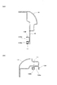
- A) is the Z section enlarged view of FIG. 3
- B) is the X arrow directional view of (A).
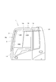
- reference numeral 1 denotes a cab provided in a working machine such as a hydraulic excavator, which has a substantially rectangular parallelepiped shape in the present embodiment, but a window opening 2 a is formed in the front surface 2 of the cab 1.
- Reference numeral 3 denotes a front window that opens and closes the window opening 2a.
- the front window 3 is configured by assembling a transparent plate 3b such as a glass plate on the upper, lower, left, and right window frames 3a.
- a pair of left and right upper rollers 4 and lower rollers 5 are rotatably attached to upper and lower portions of the left and right window frames 3a via brackets 6 and 7 and support shafts 8 and 9, respectively.
- the upper window 4 and the lower roller 5 are guided by a pair of left and right guide rails 10 which will be described later, whereby the front window 3 is housed in the closed position where the window opening 2a is closed and in the ceiling of the cab 1.
- the window opening 2a is opened and closed to the open position.
- the front window 3 in the closed position and the open position is locked at each position by a lock device (not shown).
- the window frame 3 is provided with a handle that is gripped by an operator when the front window 3 is opened and closed.
- 11 is an assist cable
- the front end side of the assist cable 11 is connected to the lower portion of the front window 3 via a link 12 that is pivotally supported by a support shaft 9 that supports the lower roller 5. It is connected.
- the base end side of the assist cable 11 reaches the ceiling rear portion of the cab 1 while being guided by the guide rail 10, and is connected to a winding device 13 disposed at the ceiling rear portion.
- the take-up device 13 includes a take-up spring (not shown) that constantly urges the assist cable 11 toward the take-up side. The urging force of the winding spring acts on the front window 3 via the assist cable 11 so that the labor required when the operator opens and closes the front window 3 can be reduced.
- the spring type is adopted in the present embodiment as described above. However, the winding type is not limited to this, but is an electric drive type driven by a motor. It may be.
- the guide rail 10 is fixed to the left and right frames 14 forming the framework structure of the cab 1 directly or via a plate 15 to guide the upper roller 4 and the lower roller 5 and guide the assist cable 11.
- the guide rail 10 has a front-side guide rail 10 ⁇ / b> A that is arranged along the front surface 2 of the cab 1, and a front-rear direction that is arranged along the ceiling surface 16 of the cab 1.
- the upper guide rail 10 ⁇ / b> B that faces is formed from an R-shaped corner guide rail 10 ⁇ / b> C that is disposed at the corner between the front surface 2 and the ceiling surface 16 of the cab 1.
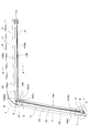
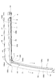
- the front guide rail 10A, the upper guide rail 10B, and the corner guide rail 10C all have roller guide portions 10Aa, 10Ba, and 10Ca having a U-shaped cross section for guiding the lower roller 5 or the upper roller 4 and the assist cable 11.
- the cable guide portions 10Ab, 10Bb, and 10Cb having a U-shaped cross section to be guided are formed side by side, but the front guide rail 10A has the cable guide portion 10Ab on the front side and the roller guide portion 10Aa on the rear side.
- the lower roller 5 is guided by the roller guide portion 10Aa of the front guide rail 10A.
- the upper guide rail 10B is arranged with the roller guide portion 10Ba on the upper side and the cable guide portion 10Bb on the lower side, and the upper roller 4 is guided to the roller guide portion 10Ba of the upper guide rail 10B. It is the composition which becomes. Further, the front portion of the roller guide portion 10Ba of the upper guide rail 10B is linearly extended toward the cab front surface 2 from the front end of the cable guide portion 10Bb, and the upper roller 4 is connected to the cab by the extension portion 10BaE. It can guide linearly toward the front surface 2. The upper roller 4 is guided in a straight line toward the cab front surface 2, so that the front window 3 is substantially omitted with respect to the rainwater intrusion prevention seal member 17 attached to the peripheral edge of the window opening 2a. It can be pressed vertically.
- the corner guide rail 10C is formed with an R-shaped roller guide portion 10Ca connected to the upper end of the roller guide portion 10Aa of the front guide rail 10A.
- the roller guide portion 10Ca allows the lower roller 5 to be connected to the cab. 1 can be guided to the front of the ceiling.
- the cable guide portion 10Cb of the corner guide rail 10C is formed on the outer diameter side of the roller guide portion 10Ca, and the cable guide portion 10Cb is connected to the upper end and the upper side of the cable guide portion 10Ab of the front guide rule 10A.
- the front end of the cable guide portion 10Bb of the guide rail 10B is formed to be connected in an R shape.
- the cable guide portion 10Ab of the front guide rule 10A is located on the front side of the roller guide portion 10Aa
- the cable guide portion 10Bb of the upper guide rail 10B is located on the lower side of the roller guide portion 10Ba.
- the cable guide portion 10Cb of the corner guide rail 10C is formed so as to connect the upper end of the cable guide portion 10Ab of the front guide rule 10A and the front end of the cable guide portion 10Bb of the upper guide rail 10B in an R shape. .
- the radius of curvature on the inner diameter side of the corner guide rail 10C is set so as to correspond to the cab 1 having a substantially rectangular parallelepiped shape. Even if it is designed to be small, the radius of curvature of the cable guide portion 10Cb can be increased. Furthermore, since the roller guide portion 10Ba of the upper guide rail 10B is located above the cable guide portion 10Bb, as described above, the roller guide portion of the upper guide rail 10B is not obstructed by the cable guide portion 10Bb. The front part of 10Ba can be extended linearly toward the cab front surface 2 from the front end of the cable guide part 10Bb.
- the upper roller 4 is located at the front end portion of the roller guide portion 10Ba of the upper guide rail 10B, while the lower roller 5 is It is located at the lower end of the roller guide portion 10Aa of the front guide rail 10A.
- the assist cable 11 passes through the cable guide portion 10Ab of the front guide rail 10A, the cable guide portion 10Cb of the corner guide rail 10C, and the cable guide portion 10Bb of the upper guide rail 10B, and from the lower portion of the front window 3 to the ceiling of the cab 1. It is wired so as to reach the winding device 13 disposed at the rear.
- the upper roller 4 is guided by the roller guide portion 10Ba of the upper guide rail 10B and moves backward, while the lower roller 5 is moved to the roller guide portion 10Aa of the front guide rail 10A.
- the movement of the front window 3 toward the opening side is reduced because the assist cable 11 is urged toward the winding side by a winding spring built in the winding device 13, thereby reducing the labor of the operator.
- the upper roller 4 is positioned at the rear end of the roller guide portion 10Ba of the upper guide rail 10B, while the lower roller 5 is It is located at the rear end of the roller guide portion 10Ca of the corner guide rail 10C.
- the upper roller 4 when closing the front window 3 in the open position, the upper roller 4 is guided by the roller guide portion 10Ba of the upper guide rail 10B and moves forward, while the lower roller 5 is a roller of the corner guide rail 10C.
- the guide part 10Ca and the front guide rail 10A are guided by the roller guide part 10Aa and move downward.
- the front part of the roller guide part 10Ba of the upper guide rail 10B is located in front of the cab rather than the front end of the cable guide part 10Bb. Since the upper roller 4 is linearly guided toward the front surface 2 of the cab by the extended portion 10BaE, the front window 3 is opened when reaching the closed position.
- the movement of the front window 3 toward the closing side is such that the assist cable 11 is urged toward the winding side by a winding spring built in the winding device 13, so that the lowering speed due to the weight of the front window 3 is reduced. As a result, the labor of the operator can be reduced.
- the guide rail 10 includes the upper roller 4 and the lower roller 5 attached to the upper and lower portions of the front window 3 and the front window 3 in order to reduce labor required to open and close the front window 3.
- the guide rail 10 is arranged along the cab ceiling surface 16 and the front guide rail 10 ⁇ / b> A arranged along the cab front surface 2.
- the upper guide rail 10B and the corner guide rail 10C disposed in the corner portion of the cab front surface 2 and the cab ceiling surface 16 are formed.
- the front guide rail 10A has a cable guide portion 10Ab on the front side.
- the guide portion 10Aa is positioned on the rear side, and the lower roller 5 is guided by the roller guide portion 10Aa of the front guide rail 10A.
- the upper guide rail 10B has the roller guide portion 10Ba on the upper side and the cable guide portion 10Bb on the lower side, and the front portion of the roller guide portion 10Ba is straighter toward the cab front surface 2 than the cable guide portion 10Bb.
- the upper roller 4 is guided by the roller guide portion 10Ba of the upper guide rail 10B, and the corner guide rail 10C is connected to the upper end of the roller guide portion 10Aa of the front guide rail 10A.
- An R-shaped roller guide portion 10Ca that guides the lower roller 5 to the front portion of the cab ceiling, and is formed on the outer diameter side of the roller guide portion 10Ca, and the upper end and upper guide of the cable guide portion 10Ab of the front guide rule 10A. Cable cable that connects the front end of the cable guide portion 10Bb of the rail 10B in an R shape. And a de portion 10Cb.
- the assist cable 11 passes through the cable guide portion 10Ab of the front guide rail 10A, the cable guide portion 10Cb of the corner guide rail 10C, and the cable guide portion 10Bb of the upper guide rail 10B, and from the lower portion of the front window 3 to the ceiling of the cab 1. It is wired so as to reach the winding device 13 disposed at the rear, and when the front window 3 is opened and closed, it moves while being pressed against the inner surface of the groove of the cable guide portion 10Cb of the corner guide rail 10C by the tension.
- the corner guide rail 10C is formed with the cable guide portion 10Cb on the outer diameter side of the roller guide portion 10Ca, for example, the inner diameter of the corner guide rail 10C can be adapted to the rectangular parallelepiped cab 1. Side, that is, the radius of curvature of the roller guide portion 10Ca is reduced. Even if measured, the radius of curvature of the cable guide portion 10Cb can be secured large, and the frictional force generated between the assist cable 11 and the cable guide portion 10Cb can be reduced. 11 and the guide rail 10 can be effectively prevented from wearing out early.
- the upper guide rail 10B is linearly extended from the cable guide portion 10Bb toward the cab front surface 2 toward the front surface of the cab, but in this case, the upper guide rail 10B Since the guide portion 10Ba is provided on the upper side of the cable guide portion 10Bb, the roller guide portion 10Ba can be extended linearly toward the cab front surface 2 without being obstructed by the cable guide portion 10Bb.
- the upper roller 4 is linearly guided toward the cab front surface 2 by the extended portion 10BaE of the roller guide portion 10Ba, so that the front window 3 has a peripheral edge of the window opening 2a when reaching the closed position.
- the seal member 17 is pressed substantially perpendicularly to the rainwater intrusion-preventing seal member 17 mounted on the portion, so that the sealing performance between the front window 3 and the seal member 17 can be ensured and the seal member 17 can be reliably secured.
- the radius of curvature of the cable guide portion 10Cb of the corner guide rail 10C can be increased to reduce the frictional force generated between the assist cable 11 and the cable guide portion 10Cb. It is also possible to ensure the sealing performance between the two, and this has a simple structure and does not require a special guide rail or a separate member, which can greatly contribute to cost reduction.
- the present invention relates to a technical field of a guide rail structure of a front window in a work vehicle such as a hydraulic excavator. Since the frictional force at the corner portion can be reduced by the configuration as in the present invention, the assist cable is generated by the frictional force. In addition, it is possible to effectively prevent the guide rail from being worn out at an early stage. In addition, there is no need for special guide rails or separate members, and the structure is simple and the sealing performance between the front window and the sealing material can be secured when the front window is closed. There is a possibility of use.
Landscapes
- Engineering & Computer Science (AREA)
- Mining & Mineral Resources (AREA)
- Civil Engineering (AREA)
- General Engineering & Computer Science (AREA)
- Structural Engineering (AREA)
- Mechanical Engineering (AREA)
- Window Of Vehicle (AREA)
- Component Parts Of Construction Machinery (AREA)
Abstract
【課題】ローラガイド部とケーブルガイド部が並設された前窓用のガイドレールにおいて、コーナー部における摩擦力を小さくすると共に、前窓閉鎖時において前窓とシール材との間のシール性を確保できるようにする。 【解決手段】 ガイドレール10を、前側ガイドレール10Aと上側ガイドレール10Bとコーナーガイドレール10Cとから形成し、前側ガイドレール10Aは、ケーブルガイド部10Abがローラガイド部10Aaの前側に位置し、上側ガイドレール10Bは、ローラガイド部10Baがケーブルガイド部10Bbの上側に位置すると共に、ローラガイド部10aの前部がキャブ前面2に向けて延長され、コーナーガイドレール10Cは、ローラガイド部10Caの外径側に、前側、上側ガイドレールのケーブルガイド部10Ab、10Bb同士を連結するケーブルガイド部10Cbが形成される構成にした。
Description
本発明は、油圧ショベル等の作業用車両における前窓のガイドレール構造の技術分野に属するものである。
一般に、油圧ショベル等の作業用車両のキャブに設けられる前窓のなかには、キャブ前面の窓用開口部を閉じる閉位置と、キャブ天井部に収納されて窓用開口部を開く開位置とに開閉自在に構成されたものがある。さらにこのものにおいて、前窓の開閉時におけるオペレータの労力を軽減するべく、先端側が前窓の下部に連結されるアシストケーブルの基端側を、キャブ後部に配設された巻取装置に巻取るように構成したアシスト機能付きのものも提供されている。
この様なアシスト機能付きの前窓において、該前窓の開閉移動をガイドするガイドレールは、キャブ前面から天井面に亘って逆L字形状に配設されることになるが、この様なガイドレールとして、従来、前窓の上下部に取付けられた上側ローラおよび下側ローラをガイドするローラガイド部と、前述したアシストケーブルをガイドするケーブルガイド部とを並設して設けたものが知られている(例えば、特許文献1、2参照)。
ところで、例えば略直方体形状のキャブに、前記ローラガイド部とケーブルガイド部とが並設されたガイドレールを配設する場合、キャブ前面とキャブ天井面とのコーナー部に配されるガイドレールコーナー部分の曲率半径が大きいと、該ガイドレールコーナー部分が室内側に突出してキャブの室内スペースを狭くしたりオペレータの視界を妨げたりするため、ガイドレールコーナー部分の曲率半径をなるべく小さくすることが要求される。しかるに、ガイドレールコーナー部分においてケーブルガイド部の曲率半径が小さいと、アシストケーブルが溝内側面に押付けられながら移動するときに発生する摩擦力が大きくなって、アシストケーブルやガイドレールが早期に摩耗するという問題が発生する。
一方、前窓が閉位置に位置している状態において該前窓と窓用開口部との間隙から雨水が浸入することを防止するべく、前窓開口部の周縁部にはシール材が装着されるが、前窓を閉じるときにシール材に対して前窓を垂直に押付けることができないと、良好なシール性を確保できないという問題もある。
そこで、特許文献1のものは、ガイドレールコーナー部分のケーブルガイド部に、耐摩耗性や潤滑性を有する摺動部材を設けたり、ケーブルガイドローラを配設したりすることで、ガイドレールコーナー部分においてアシストケーブルとガイドレールとの間に発生する摩擦を軽減できるようにしている。
一方、特許文献2のものには、前窓とシール材とのシール性を確保するために、前窓をシール材に対して垂直方向に押付けるための装置が提唱されている。
特開2002-327571号公報
特開2000-274135号公報
この様なアシスト機能付きの前窓において、該前窓の開閉移動をガイドするガイドレールは、キャブ前面から天井面に亘って逆L字形状に配設されることになるが、この様なガイドレールとして、従来、前窓の上下部に取付けられた上側ローラおよび下側ローラをガイドするローラガイド部と、前述したアシストケーブルをガイドするケーブルガイド部とを並設して設けたものが知られている(例えば、特許文献1、2参照)。
ところで、例えば略直方体形状のキャブに、前記ローラガイド部とケーブルガイド部とが並設されたガイドレールを配設する場合、キャブ前面とキャブ天井面とのコーナー部に配されるガイドレールコーナー部分の曲率半径が大きいと、該ガイドレールコーナー部分が室内側に突出してキャブの室内スペースを狭くしたりオペレータの視界を妨げたりするため、ガイドレールコーナー部分の曲率半径をなるべく小さくすることが要求される。しかるに、ガイドレールコーナー部分においてケーブルガイド部の曲率半径が小さいと、アシストケーブルが溝内側面に押付けられながら移動するときに発生する摩擦力が大きくなって、アシストケーブルやガイドレールが早期に摩耗するという問題が発生する。
一方、前窓が閉位置に位置している状態において該前窓と窓用開口部との間隙から雨水が浸入することを防止するべく、前窓開口部の周縁部にはシール材が装着されるが、前窓を閉じるときにシール材に対して前窓を垂直に押付けることができないと、良好なシール性を確保できないという問題もある。
そこで、特許文献1のものは、ガイドレールコーナー部分のケーブルガイド部に、耐摩耗性や潤滑性を有する摺動部材を設けたり、ケーブルガイドローラを配設したりすることで、ガイドレールコーナー部分においてアシストケーブルとガイドレールとの間に発生する摩擦を軽減できるようにしている。
一方、特許文献2のものには、前窓とシール材とのシール性を確保するために、前窓をシール材に対して垂直方向に押付けるための装置が提唱されている。
しかるに、前記特許文献1のものにおいて、摺動部材を用いる場合には、該摺動部材が埋め込まれた特殊なガイドレールが必要であって、コストが高くなり汎用的でないという問題がある。また、ケーブルガイドローラを配設する場合には、コーナー部の曲率半径に相当する大きなケーブルガイドローラを採用すると、該ケーブルガイドローラが室内側に大きく突出して邪魔になるため、多数の小さなケーブルガイドローラを配する方が好ましいが、そうすると、部品点数が増えて、ケーブルガイドローラ取付けの手間もかかり、やはりコスト高になるという問題がある。
一方、特許文献2のものは、前窓をシール材に垂直に押付けるための装置として、レバー、スプリング、ストッパ、ストッパ解除体等の多数の部品が必要であって、構造が複雑でコストも高くなるという問題があり、これらに本発明が解決しようとする課題がある。
一方、特許文献2のものは、前窓をシール材に垂直に押付けるための装置として、レバー、スプリング、ストッパ、ストッパ解除体等の多数の部品が必要であって、構造が複雑でコストも高くなるという問題があり、これらに本発明が解決しようとする課題がある。
本発明は、上記の如き実情に鑑みこれらの課題を解決することを目的として創作されたものであって、請求項1の発明は、キャブ前面の窓用開口部を閉じる閉位置とキャブ天井部に収納されて窓用開口部を開く開位置とに開閉自在な前窓を設けてなる作業用車両において、前記前窓の開閉をガイドする左右一対のガイドレールを、前窓の上下部に取付けられた上側ローラおよび下側ローラをガイドするローラガイド部と、先端側が前窓の下部に連結され基端側がキャブ後部に配設の巻取装置に連結されるアシストケーブルをガイドするケーブルガイド部とを並設して構成するにあたり、前記ガイドレールを、キャブ前面に沿うように配される前側ガイドレールと、キャブ天井面に沿うように配される上側ガイドレールと、キャブ前面とキャブ天井面とのコーナー部に配されるコーナーガイドレールとから形成すると共に、前側ガイドレールは、ケーブルガイド部が前側にローラガイド部が後側に位置し、且つ、前側ガイドレールのローラガイド部には下側ローラがガイドされる構成であり、上側ガイドレールは、ローラガイド部が上側にケーブルガイド部が下側に位置すると共に、ローラガイド部の前部がケーブルガイド部よりもキャブ前面に向けて延長され、且つ、上側ガイドレールのローラガイド部には上側ローラがガイドされる構成である一方、コーナーガイドレールは、前側ガイドレールのローラガイド部の上端に連結され、下側ローラをキャブ天井前部までガイドするR状のローラガイド部と、該ローラガイド部の外径側に設けられ、前側ガイドルールのケーブルガイド部の上端と上側ガイドレールのケーブルガイド部の前端とをR状に連結するケーブルガイド部とを有することを特徴とする作業用車両における前窓のガイドレール構造である。
請求項1の発明とすることにより、コーナーガイドレールは、ローラガイド部の外径側にケーブルガイド部が形成されることになり、而して、例えば直方体形状のキャブに対応できるようにコーナーガイドレールの内径側の曲率半径を小さく設計しても、ケーブルガイド部の曲率半径を大きく確保できることになって、アシストケーブルとケーブルガイド部との間に発生する摩擦力を小さくすることができ、よって、摩擦力によってアシストケーブルおよびガイドレールが早期に摩耗してしまうことを有効に防止できる。さらに、前窓が閉位置に達するときに、上側ローラが上側ガイドレールのローラガイド部の延長部分によってキャブ前面に向けてガイドされることで、前窓を、窓用開口部の周縁部に装着される雨水侵入防止用のシール部材に対して略垂直に押付けることができ、これによって、前窓とシール部材との間のシール性を確実に確保できることになる。この結果、アシストケーブルとケーブルガイド部との間に発生する摩擦力を小さくしてアシストケーブルおよびガイドレールを有効に保護できるものでありながら、前窓とシール部材との間のシール性も確保できることになり、しかも、特殊なガイドレールや別途部材を必要とせず、簡単な構造のものであるから、コスト低減に大きく貢献できる。
1 キャブ
3 前窓
4 上側ローラ
5 下側ローラ
10 ガイドレール
10A 前側ガイドレール
10Aa ローラガイド部
10Ab ケーブルガイド部
10B 上側ガイドレール
10Ba ローラガイド部
10BaE 延長部分
10Bb ケーブルガイド部
10C コーナーガイドレール
10Ca ローラガイド部
10Cb ケーブルガイド部
11 アシストケーブル
3 前窓
4 上側ローラ
5 下側ローラ
10 ガイドレール
10A 前側ガイドレール
10Aa ローラガイド部
10Ab ケーブルガイド部
10B 上側ガイドレール
10Ba ローラガイド部
10BaE 延長部分
10Bb ケーブルガイド部
10C コーナーガイドレール
10Ca ローラガイド部
10Cb ケーブルガイド部
11 アシストケーブル
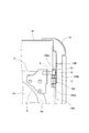
次に、本発明の実施の形態について、図面に基づいて説明する。図において、1は油圧ショベル等の作業用機械に設けられるキャブであって、本実施の形態では略直方体形状をしているが、該キャブ1の前面2には、窓用開口部2aが開設されている。また、3は前記窓用開口部2aを開閉する前窓であって、該前窓3は、上下左右の窓枠3aにガラス板等の透明板3bを組付けて構成されるものであるが、左右の窓枠3aの上下部には、左右一対の上側ローラ4、下側ローラ5がそれぞれブラケット6、7および支軸8、9を介して回転自在に取付けられている。そしてこれら上側ローラ4、下側ローラ5が後述する左右一対のガイドレール10にガイドされることによって、前窓3は、窓用開口部2aを閉じる閉位置と、キャブ1の天井部に収納されて窓用開口部2aを開く開位置とに開閉移動する構成になっている。尚、閉位置、開位置の前窓3は、図示しないロック装置によって各位置にロックされるようになっている。また、図示しないが、窓枠3には、該前窓3を開閉するときにオペレータが把持する把手が取付けられている。
一方、11はアシストケーブルであって、該アシストケーブル11の先端側は、前記下側ローラ5を支持する支軸9に揺動自在に軸承されるリンク12を介して、前窓3の下部に連結されている。一方、アシストケーブル11の基端側は、前記ガイドレール10にガイドされる状態でキャブ1の天井後部まで至り、該天井後部に配設された巻取装置13に連結されていると共に、該巻取装置13には、アシストケーブル11を常に巻取り側に付勢する巻取りバネ(図示せず)が内装されている。そして、該巻取りバネの付勢力がアシストケーブル11を介して前窓3に作用することによって、オペレータが前窓3を開閉するときの労力を軽減できる構成になっている。尚、アシストケーブル11を巻取る巻取装置13としては、本実施の形態では前述したようにバネ式が採用されているが、これに限定されることなく、モータで駆動する電動駆動式のものであっても良い。
前記ガイドレール10は、キャブ1の骨組構造体をなす左右のフレーム14に直接或いはプレート15を介して固定されていて、前記上側ローラ4および下側ローラ5をガイドすると共に、アシストケーブル11をガイドするものであるが、該ガイドレール10は、キャブ1の前面2に沿うように配される上下方向を向く前側ガイドレール10Aと、キャブ1の天井面16に沿うように配される前後方向を向く上側ガイドレール10Bと、キャブ1の前面2と天井面16とのコーナー部に配されるR状のコーナーガイドレール10Cとから形成されている。
これら前側ガイドレール10A、上側ガイドレール10B、コーナーガイドレール10Cは、何れも、下側ローラ5或いは上側ローラ4をガイドする断面コ字形状のローラガイド部10Aa、10Ba、10Caと、アシストケーブル11をガイドする断面コ字形状のケーブルガイド部10Ab、10Bb、10Cbとが並設する状態で形成されているが、前側ガイドレール10Aは、ケーブルガイド部10Abが前側にローラガイド部10Aaが後側に位置する状態で配されると共に、前側ガイドレール10Aのローラガイド部10Aaには、下側ローラ5がガイドされる構成になっている。
また、上側ガイドレール10Bは、ローラガイド部10Baが上側にケーブルガイド部10Bbが下側に位置する状態で配されると共に、上側ガイドレール10Bのローラガイド部10Baには、上側ローラ4がガイドされる構成になっている。さらに、上側ガイドレール10Bのローラガイド部10Baの前部は、ケーブルガイド部10Bbの前端よりもキャブ前面2に向けて直線状に延長されており、該延長部分10BaEによって、上側ローラ4を、キャブ前面2に向けて直線状にガイドすることができるようになっている。そして、該上側ローラ4がキャブ前面2に向けて直線状にガイドされることで、窓用開口部2aの周縁部に装着された雨水侵入防止用のシール部材17に対して前窓3を略垂直に押付けることができるようになっている。
一方、コーナーガイドレール10Cは、前側ガイドレール10Aのローラガイド部10Aaの上端に連結されるR状のローラガイド部10Caが形成されており、該ローラガイド部10Caによって、下側ローラ5を、キャブ1の天井前部までガイドすることができるようになっている。また、コーナーガイドレール10Cのケーブルガイド部10Cbは、前記ローラガイド部10Caの外径側に形成されているが、該ケーブルガイド部10Cbは、前側ガイドルール10Aのケーブルガイド部10Abの上端と、上側ガイドレール10Bのケーブルガイド部10Bbの前端とをR状に連結するように形成されている。
ここで、前述したように、前側ガイドルール10Aのケーブルガイド部10Abはローラガイド部10Aaの前側に、また、上側ガイドレール10Bのケーブルガイド部10Bbはローラガイド部10Baの下側に位置していると共に、コーナーガイドレール10Cのケーブルガイド部10Cbは、前側ガイドルール10Aのケーブルガイド部10Abの上端と、上側ガイドレール10Bのケーブルガイド部10Bbの前端とをR状に連結するように形成されている。そして、コーナーガイドレール10Cのケーブルガイド部10Cbは、ローラガイド部10Caの外径側に位置しているから、略直方体形状のキャブ1に対応できるようにコーナーガイドレール10Cの内径側の曲率半径を小さく設計しても、ケーブルガイド部10Cbの曲率半径を大きくすることができる。さらに、上側ガイドレール10Bのローラガイド部10Baはケーブルガイド部10Bbの上側に位置しているから、該ケーブルガイド部10Bbに邪魔されることなく、前述したように、上側ガイドレール10Bのローラガイド部10Baの前部を、ケーブルガイド部10Bbの前端よりもキャブ前面2に向けて直線状に延長させることができる。
そして、前窓3が閉位置に位置している状態では、図3に示すごとく、上側ローラ4は、上側ガイドレール10Bのローラガイド部10Baの前端部に位置する一方、下側ローラ5は、前側ガイドレール10Aのローラガイド部10Aaの下端部に位置している。また、アシストケーブル11は、前側ガイドレール10Aのケーブルガイド部10Ab、コーナーガイドレール10Cのケーブルガイド部10Cb、上側ガイドレール10Bのケーブルガイド部10Bbを通って、前窓3の下部からキャブ1の天井後部に配設の巻取装置13に至るように配線される。
前記閉位置の前窓3を開くと、上側ローラ4は、上側ガイドレール10Bのローラガイド部10Baにガイドされて後方に移動する一方、下側ローラ5は、前側ガイドレール10Aのローラガイド部10Aaにガイドされて上方に移動し、さらにコーナーガイドレール10Cのローラガイド部10Caに至る。該前窓3の開側への移動は、アシストケーブル11が巻取装置13に内装の巻取りバネにより巻取り側に付勢されていることで、オペレータの労力が軽減される。
さらに、前記前窓3が開位置に達した状態では、図4に示すごとく、上側ローラ4は、上側ガイドレール10Bのローラガイド部10Baの後端部に位置する一方、下側ローラ5は、コーナーガイドレール10Cのローラガイド部10Caの後端部に位置するようになっている。
一方、開位置の前窓3を閉じる場合には、上側ローラ4は、上側ガイドレール10Bのローラガイド部10Baにガイドされて前方に移動する一方、下側ローラ5は、コーナーガイドレール10Cのローラガイド部10Caおよび前側ガイドレール10Aのローラガイド部10Aaにガイドされて下方に移動するが、この場合、上側ガイドレール10Bのローラガイド部10Baの前部は、ケーブルガイド部10Bbの前端よりもキャブ前面2に向けて直線状に延長されているから、該延長部分10BaEによって上側ローラ4がキャブ前面2に向けて直線状にガイドされることで、前窓3は、閉位置に達するときに、窓用開口部2aの周縁部に装着された雨水侵入防止用のシール部材17に対して略垂直に押付けられることになる。該前窓3の閉側への移動は、アシストケーブル11が巻取装置13に内装の巻取りバネにより巻取り側に付勢されていることで、前窓3の自重による降下速度が減速され、これによりオペレータの労力を軽減できるようになっている。
叙述の如く構成された本形態において、ガイドレール10は、前窓3の上下部に取付けられた上側ローラ4および下側ローラ5と、前窓3の開閉に要する労力を軽減するべく前窓3の下部に連結されるアシストケーブル11とをガイドすることになるが、該ガイドレール10は、キャブ前面2に沿うように配される前側ガイドレール10Aと、キャブ天井面16に沿うように配される上側ガイドレール10Bと、キャブ前面2とキャブ天井面16とのコーナー部に配されるコーナーガイドレール10Cとから形成されており、そして、前側ガイドレール10Aは、ケーブルガイド部10Abが前側にローラガイド部10Aaが後側に位置し、且つ、前側ガイドレール10Aのローラガイド部10Aaには下側ローラ5がガイドされる構成であり、また、上側ガイドレール10Bは、ローラガイド部10Baが上側にケーブルガイド部10Bbが下側に位置すると共に、ローラガイド部10Baの前部がケーブルガイド部10Bbよりもキャブ前面2に向けて直線状に延長され、且つ、上側ガイドレール10Bのローラガイド部10Baには上側ローラ4がガイドされる構成であり、さらに、コーナーガイドレール10Cは、前側ガイドレール10Aのローラガイド部10Aaの上端に連結されて下側ローラ5をキャブ天井前部までガイドするR状のローラガイド部10Caと、該ローラガイド部10Caの外径側に形成され、前側ガイドルール10Aのケーブルガイド部10Abの上端と上側ガイドレール10Bのケーブルガイド部10Bbの前端とをR状に連結するケーブルガイド部10Cbとを有している。
そして、アシストケーブル11は、前側ガイドレール10Aのケーブルガイド部10Ab、コーナーガイドレール10Cのケーブルガイド部10Cb、上側ガイドレール10Bのケーブルガイド部10Bbを通って、前窓3の下部からキャブ1の天井後部に配設の巻取装置13に至るように配線されると共に、前窓3の開閉時には、その張力によって、コーナーガイドレール10Cのケーブルガイド部10Cbの溝内側面に押付けられながら移動することになるが、この場合に、コーナーガイドレール10Cは、ローラガイド部10Caの外径側にケーブルガイド部10Cbが形成されているから、例えば直方体形状のキャブ1に対応できるようにコーナーガイドレール10Cの内径側、つまりローラガイド部10Caの曲率半径を小さく設計しても、ケーブルガイド部10Cbの曲率半径を大きく確保できることになって、アシストケーブル11とケーブルガイド部10Cbとの間に発生する摩擦力を小さくすることができ、よって、摩擦力によってアシストケーブル11およびガイドレール10が早期に摩耗してしまうことを有効に防止できる。
さらにこのものにおいて、上側ガイドレール10Bは、ローラガイド部10Baの前部がケーブルガイド部10Bbよりもキャブ前面2に向けて直線状に延長されているが、この場合、上側ガイドレール10Bは、ローラガイド部10Baがケーブルガイド部10Bbの上側に設けられているから、ケーブルガイド部10Bbに邪魔されることなくローラガイド部10Baをキャブ前面2に向けて直線状に延長させることができる。そして、上記ローラガイド部10Baの延長部分10BaEによって上側ローラ4がキャブ前面2に向けて直線状にガイドされることで、前窓3は、閉位置に達するときに、窓用開口部2aの周縁部に装着された雨水侵入防止用のシール部材17に対して略垂直に押付けられることになり、よって、前窓3とシール部材17との間のシール性を確実に確保できると共に、シール部材17が前窓3に擦られて早期に損傷してしまうような不具合をなくすことができる。
この結果、コーナーガイドレール10Cのケーブルガイド部10Cbの曲率半径を大きくしてアシストケーブル11とケーブルガイド部10Cbとの間に発生する摩擦力を小さくできるものでありながら、前窓3とシール部材17との間のシール性も確保できることになり、しかもこのものは、簡単な構造のものであって、特殊なガイドレールや別途部材を必要としないから、コスト低減に大きく貢献できる。
本発明は、油圧ショベル等の作業用車両における前窓のガイドレール構造の技術分野に関するものであり、本発明のごとく構成することにより、コーナー部における摩擦力を小さく出来るため、摩擦力によってアシストケーブルおよびガイドレールが早期に摩耗してしまうことを有効に防止できる。さらに、特殊なガイドレールや別途部材を必要とせず、簡単な構造で、前窓閉鎖時において前窓とシール材との間のシール性を確保できるため、コスト低減に大きく貢献できるという産業上の利用可能性がある。
Claims (1)
- キャブ前面の窓用開口部を閉じる閉位置とキャブ天井部に収納されて窓用開口部を開く開位置とに開閉自在な前窓を設けてなる作業用車両において、前記前窓の開閉をガイドする左右一対のガイドレールを、前窓の上下部に取付けられた上側ローラおよび下側ローラをガイドするローラガイド部と、先端側が前窓の下部に連結され基端側がキャブ後部に配設の巻取装置に連結されるアシストケーブルをガイドするケーブルガイド部とを並設して構成するにあたり、前記ガイドレールを、キャブ前面に沿うように配される前側ガイドレールと、キャブ天井面に沿うように配される上側ガイドレールと、キャブ前面とキャブ天井面とのコーナー部に配されるコーナーガイドレールとから形成すると共に、前側ガイドレールは、ケーブルガイド部が前側にローラガイド部が後側に位置し、且つ、前側ガイドレールのローラガイド部には下側ローラがガイドされる構成であり、上側ガイドレールは、ローラガイド部が上側にケーブルガイド部が下側に位置すると共に、ローラガイド部の前部がケーブルガイド部よりもキャブ前面に向けて延長され、且つ、上側ガイドレールのローラガイド部には上側ローラがガイドされる構成である一方、コーナーガイドレールは、前側ガイドレールのローラガイド部の上端に連結され、下側ローラをキャブ天井前部までガイドするR状のローラガイド部と、該ローラガイド部の外径側に設けられ、前側ガイドルールのケーブルガイド部の上端と上側ガイドレールのケーブルガイド部の前端とをR状に連結するケーブルガイド部とを有することを特徴とする作業用車両における前窓のガイドレール構造。
Priority Applications (3)
| Application Number | Priority Date | Filing Date | Title |
|---|---|---|---|
| EP08871896A EP2236334B1 (en) | 2008-01-28 | 2008-12-16 | Guide-rail structure of front window in working vehicle |
| US12/812,504 US7922237B2 (en) | 2008-01-28 | 2008-12-16 | Guide-rail structure of front window in working vehicle |
| CN2008801199570A CN101896371B (zh) | 2008-01-28 | 2008-12-16 | 工程车辆中的前窗的导轨结构 |
Applications Claiming Priority (2)
| Application Number | Priority Date | Filing Date | Title |
|---|---|---|---|
| JP2008-015983 | 2008-01-28 | ||
| JP2008015983A JP4424688B2 (ja) | 2008-01-28 | 2008-01-28 | 作業用車両における前窓のガイドレール構造 |
Publications (1)
| Publication Number | Publication Date |
|---|---|
| WO2009095972A1 true WO2009095972A1 (ja) | 2009-08-06 |
Family
ID=40912343
Family Applications (1)
| Application Number | Title | Priority Date | Filing Date |
|---|---|---|---|
| PCT/JP2008/003784 Ceased WO2009095972A1 (ja) | 2008-01-28 | 2008-12-16 | 作業用車両における前窓のガイドレール構造 |
Country Status (5)
| Country | Link |
|---|---|
| US (1) | US7922237B2 (ja) |
| EP (1) | EP2236334B1 (ja) |
| JP (1) | JP4424688B2 (ja) |
| CN (1) | CN101896371B (ja) |
| WO (1) | WO2009095972A1 (ja) |
Families Citing this family (10)
| Publication number | Priority date | Publication date | Assignee | Title |
|---|---|---|---|---|
| US8292355B2 (en) * | 2010-10-26 | 2012-10-23 | Miller Michael C | Vehicle roof with retractable windshield |
| CZ21992U1 (cs) * | 2011-02-21 | 2011-03-24 | Dfk Cab, S.R.O. | Kabina vozidla |
| JP5599758B2 (ja) * | 2011-05-19 | 2014-10-01 | 日立建機株式会社 | 開口閉塞カバーおよび該開口閉塞カバーを備えた建設機械 |
| KR20140044815A (ko) * | 2011-06-13 | 2014-04-15 | 히다치 겡키 가부시키 가이샤 | 건설 기계 |
| CN102352714B (zh) * | 2011-09-20 | 2015-04-08 | 柳工常州机械有限公司 | 挖掘机驾驶室前活动窗滑轨 |
| JP2015093595A (ja) * | 2013-11-13 | 2015-05-18 | キャタピラー エス エー アール エル | 前窓のガイドレール構造 |
| JP6124345B2 (ja) * | 2013-12-05 | 2017-05-10 | キャタピラー エス エー アール エル | 前窓のガイドレール構造 |
| JP6549895B2 (ja) * | 2015-05-19 | 2019-07-24 | 株式会社日立製作所 | 熱交換器ユニット |
| JP7238720B2 (ja) * | 2019-09-26 | 2023-03-14 | コベルコ建機株式会社 | 建設機械のキャブ |
| US11628748B2 (en) | 2020-07-08 | 2023-04-18 | Oshkosh Corporation | Visibility enhancements for delivery vehicle |
Citations (5)
| Publication number | Priority date | Publication date | Assignee | Title |
|---|---|---|---|---|
| JPH054516A (ja) * | 1991-06-27 | 1993-01-14 | Nippon Cable Syst Inc | 建設機械用キヤビンのフロントウインド開閉装置 |
| JPH0687462U (ja) * | 1993-05-11 | 1994-12-22 | 八千代工業株式会社 | 窓開閉装置 |
| JPH07279200A (ja) * | 1994-03-31 | 1995-10-24 | Yachiyo Kogyo Kk | 窓開閉装置 |
| JP2000274135A (ja) | 1999-03-25 | 2000-10-03 | Shin Caterpillar Mitsubishi Ltd | 開閉装置 |
| JP2002327571A (ja) | 2001-05-02 | 2002-11-15 | Komatsu Ltd | 作業車両用キャブの前窓開閉装置 |
Family Cites Families (13)
| Publication number | Priority date | Publication date | Assignee | Title |
|---|---|---|---|---|
| US3078917A (en) * | 1959-02-26 | 1963-02-26 | Walter Balfour & Co Inc | Rolling type closure construction |
| US3385459A (en) * | 1966-03-02 | 1968-05-28 | Federated Dept Stores Inc | Cargo transporting apparatus |
| US4775180A (en) * | 1987-11-10 | 1988-10-04 | Phillips Arthur J | Automatic retractable shade |
| US4889381A (en) * | 1988-03-25 | 1989-12-26 | American & Overseas Corporation | Retractable truck bed cover apparatus |
| US5044686A (en) * | 1989-06-19 | 1991-09-03 | Acenbrack Donald F | Retractable horizontal conveyance shade apparatus |
| US5165746A (en) * | 1991-03-27 | 1992-11-24 | Dorso Trailer Sales Inc. | Polymeric articulated beverage body door |
| JPH0687462A (ja) | 1992-09-08 | 1994-03-29 | Nippon Toreele Mobil Kk | 多軸トレ−ラ−の操舵機構 |
| US5330246A (en) * | 1992-11-18 | 1994-07-19 | Bernardo Richard G | Slat block and guide track apparatus for rolling truck bed cover |
| WO1994023138A1 (fr) * | 1993-03-31 | 1994-10-13 | Kabushiki Kaisha Komatsu Seisakusho | Procede de commande automatique de l'ouverture et de la fermeture de la fenetre d'une cabine de conducteur d'engin de travaux et dispositif permettant la mise en ×uvre dudit procede |
| JP3175879B2 (ja) * | 1993-07-23 | 2001-06-11 | 株式会社小松製作所 | 作業車両の窓自動開閉制御装置 |
| US5547214A (en) * | 1995-01-23 | 1996-08-20 | Alliedsignal Inc. | Side impact soft pack air bag module |
| JP4133109B2 (ja) * | 2002-08-20 | 2008-08-13 | 新キャタピラー三菱株式会社 | 建設機械におけるシャッター式のガード装置 |
| CN2918686Y (zh) * | 2006-05-31 | 2007-07-04 | 三一重机有限公司 | 可开闭式驾驶室前窗 |
-
2008
- 2008-01-28 JP JP2008015983A patent/JP4424688B2/ja active Active
- 2008-12-16 WO PCT/JP2008/003784 patent/WO2009095972A1/ja not_active Ceased
- 2008-12-16 EP EP08871896A patent/EP2236334B1/en not_active Not-in-force
- 2008-12-16 CN CN2008801199570A patent/CN101896371B/zh not_active Expired - Fee Related
- 2008-12-16 US US12/812,504 patent/US7922237B2/en active Active
Patent Citations (5)
| Publication number | Priority date | Publication date | Assignee | Title |
|---|---|---|---|---|
| JPH054516A (ja) * | 1991-06-27 | 1993-01-14 | Nippon Cable Syst Inc | 建設機械用キヤビンのフロントウインド開閉装置 |
| JPH0687462U (ja) * | 1993-05-11 | 1994-12-22 | 八千代工業株式会社 | 窓開閉装置 |
| JPH07279200A (ja) * | 1994-03-31 | 1995-10-24 | Yachiyo Kogyo Kk | 窓開閉装置 |
| JP2000274135A (ja) | 1999-03-25 | 2000-10-03 | Shin Caterpillar Mitsubishi Ltd | 開閉装置 |
| JP2002327571A (ja) | 2001-05-02 | 2002-11-15 | Komatsu Ltd | 作業車両用キャブの前窓開閉装置 |
Non-Patent Citations (1)
| Title |
|---|
| See also references of EP2236334A4 * |
Also Published As
| Publication number | Publication date |
|---|---|
| CN101896371B (zh) | 2012-03-21 |
| US7922237B2 (en) | 2011-04-12 |
| JP2009173228A (ja) | 2009-08-06 |
| JP4424688B2 (ja) | 2010-03-03 |
| CN101896371A (zh) | 2010-11-24 |
| EP2236334B1 (en) | 2012-11-14 |
| EP2236334A1 (en) | 2010-10-06 |
| EP2236334A4 (en) | 2011-12-28 |
| US20100283290A1 (en) | 2010-11-11 |
Similar Documents
| Publication | Publication Date | Title |
|---|---|---|
| JP4424688B2 (ja) | 作業用車両における前窓のガイドレール構造 | |
| JP5140129B2 (ja) | サンルーフ装置 | |
| US9321333B2 (en) | Slide door apparatus for vehicle | |
| US20090224575A1 (en) | Subassembly for a sliding roof | |
| WO2014061637A1 (ja) | 車両用自動開閉装置 | |
| JP6124345B2 (ja) | 前窓のガイドレール構造 | |
| JP4062331B2 (ja) | 建設機械の前窓開閉装置 | |
| WO2013069154A1 (ja) | エレベータのかごにおける気密装置及び気密装置を備えたエレベータのかご | |
| JP2011045979A (ja) | 引戸式片開き2枚扉装置 | |
| WO2018151292A1 (ja) | 開閉体開閉機構 | |
| JPWO2004106213A1 (ja) | エレベータのドア装置 | |
| JP2006008121A (ja) | 車両用開放式屋根構造 | |
| JP7413318B2 (ja) | ケーブルの弛み除去機構およびサンシェード開閉装置 | |
| JP2015168493A (ja) | エレベータのドア開閉装置 | |
| KR20140106192A (ko) | 선루프용 개폐장치 | |
| JP2004278026A (ja) | 開閉装置 | |
| JP2009101872A (ja) | 車輌の扉開閉機構 | |
| JP2009166953A (ja) | エレベータのドア装置 | |
| CN204196660U (zh) | 前窗导轨结构 | |
| JP2004217392A (ja) | エレベータの扉装置 | |
| JP2000108673A (ja) | 自動車用開口ル―フ構造 | |
| KR20140115131A (ko) | 블라인드타입 선루프장치 | |
| JP7306808B2 (ja) | 作業機械のキャビン及び作業機械 | |
| JP2009166970A (ja) | エレベータの戸ガイド装置 | |
| JP2008174014A (ja) | 建設機械のエンジンカバー |
Legal Events
| Date | Code | Title | Description |
|---|---|---|---|
| WWE | Wipo information: entry into national phase |
Ref document number: 200880119957.0 Country of ref document: CN |
|
| 121 | Ep: the epo has been informed by wipo that ep was designated in this application |
Ref document number: 08871896 Country of ref document: EP Kind code of ref document: A1 |
|
| WWE | Wipo information: entry into national phase |
Ref document number: 2008871896 Country of ref document: EP |
|
| WWE | Wipo information: entry into national phase |
Ref document number: 12812504 Country of ref document: US |
|
| NENP | Non-entry into the national phase |
Ref country code: DE |