WO2009096176A1 - Dispositif électronique - Google Patents
Dispositif électronique Download PDFInfo
- Publication number
- WO2009096176A1 WO2009096176A1 PCT/JP2009/000318 JP2009000318W WO2009096176A1 WO 2009096176 A1 WO2009096176 A1 WO 2009096176A1 JP 2009000318 W JP2009000318 W JP 2009000318W WO 2009096176 A1 WO2009096176 A1 WO 2009096176A1
- Authority
- WO
- WIPO (PCT)
- Prior art keywords
- setting
- display
- item
- electronic device
- information
- Prior art date
- Legal status (The legal status is an assumption and is not a legal conclusion. Google has not performed a legal analysis and makes no representation as to the accuracy of the status listed.)
- Ceased
Links
Images



Classifications
-
- H—ELECTRICITY
- H04—ELECTRIC COMMUNICATION TECHNIQUE
- H04N—PICTORIAL COMMUNICATION, e.g. TELEVISION
- H04N23/00—Cameras or camera modules comprising electronic image sensors; Control thereof
- H04N23/60—Control of cameras or camera modules
- H04N23/62—Control of parameters via user interfaces
-
- H—ELECTRICITY
- H04—ELECTRIC COMMUNICATION TECHNIQUE
- H04N—PICTORIAL COMMUNICATION, e.g. TELEVISION
- H04N2101/00—Still video cameras
Definitions
- the present invention relates to an electronic device whose operation is controlled based on setting contents that can be changed by a user. More specifically, the present invention relates to an electronic device whose operation is controlled by displaying pictorial symbols corresponding to a plurality of setting items on a display device and causing the user to change the setting contents.
- Patent Document 1 discloses an electronic camera equipped with a liquid crystal monitor.
- a cross key and a liquid crystal monitor are arranged on the back of the camera.
- a menu balloon for performing various settings for the electronic camera is displayed on an OSD (On Screen Display) in addition to a captured image and a reproduced image.
- the user operates the cross key to select a desired menu item and change the setting. This makes it possible to input various setting contents even if the number of operation keys is small.
- an electronic camera with relatively good operability is provided. JP 2001-2111368 A
- menu balloon displayed on the LCD monitor is a simplified display of the contents of each operation setting, the menu balloon alone may not understand what it means.
- An object of the present invention is to provide an electronic device with high operability by making it easy to convey the contents of each operation setting to the operator and simplifying the display of the setting screen as much as possible.
- An electronic device is an electronic device that operates in accordance with a setting for each of a plurality of selection items for selecting an operation condition, and an operation unit operated by a user to change the setting; A plurality of pictograms corresponding to each of the items, and for the selected pictogram, a display unit for displaying information on a selected item that is an item corresponding to the pictorial symbol selected, and A control unit that controls display of the display unit so that display of the information on the selected item is canceled when an operation for changing the setting of the selected item is performed via the operation unit.
- the display unit displays information on the selected item and information on the setting currently applied to the selected item. It may be displayed.
- the display unit displays pictorial symbols corresponding to each of a plurality of selectable settings with respect to the selected item, and an operation for changing the setting of the selected item is performed via the operation unit.
- the control unit may change the display of the display unit so as to display setting information corresponding to the pictorial symbol selected by the operation.
- the display unit may simultaneously display a plurality of pictorial symbols corresponding to each of a plurality of selectable settings for the selected item.
- the display unit may display a pictorial symbol corresponding to the setting currently applied to the item that cannot be changed for the item that cannot be changed from among the plurality of items.
- the display unit displays a description of a function of the electronic device as the information on the selected item, and the setting information includes numerical values required for turning on / off the function and executing the function. At least one description may be displayed.
- the operation unit may accept an operation for changing the setting of the selected item and an operation for selecting one of the pictorial symbols corresponding to the plurality of items by different operation methods.
- the information of the selected item corresponding to the selected pictorial symbol is displayed on the display unit, an operating condition setting environment that is easier to understand for any user is provided. Can be provided. Thereby, since the user can easily understand the meaning of the pictogram, it can be operated smoothly. Furthermore, when an operation for changing the setting of the selected item is performed, the display of the information of the selected item is canceled, so that the setting screen can be simplified and an erroneous operation can be prevented. According to these, the operability of the electronic device can be greatly improved.
- FIG. 1 is a block diagram illustrating a configuration of a digital camera 100 according to an embodiment of the present invention.
- 2 is a rear view of the digital camera 100.
- FIG. It is a figure which shows a state when the right key 183 is pressed after displaying a quick menu on the liquid crystal monitor 170 by control of the controller 150.
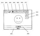
- FIG. FIG. 4 is a diagram showing a display example of a quick menu in which only a setting information display field D90 is displayed after the up key 182 or the down key 184 is pressed from the state of FIG. It is a figure which shows the example of a display of a quick menu when the setting of the operation condition selection item of "LCD brightness" is changeable by operating the right key 183 or the left key 185.
- FIG. 6 is a state transition diagram regarding the operation of the digital camera 100.
- FIG. 1 is a block diagram illustrating a configuration of a digital camera 100 according to an embodiment of the present invention.
- 2 is a rear view of the digital camera 100
- FIG. 1 is a block diagram showing the configuration of the digital camera 100 according to the present embodiment.
- the digital camera 100 includes an optical system 120, a CCD image sensor 121, an AD converter (ADC) 122, an image processing unit 130, a buffer memory 140, a flash memory 141, a controller 150, and a memory card 161.
- the optical system 120 collects light from the subject and forms a subject image on the CCD image sensor 121.
- the optical system 120 can be configured by a lens or the like. Any number of lens groups may be used in the optical system 120.
- the CCD image sensor 121 is an image sensor that captures a subject image and generates image data.
- another image pickup device such as a CMOS image sensor or an NMOS image sensor may be used.
- the AD converter 122 converts the image data generated by the CCD image sensor 121 from analog format data to digital format data.
- the image processing unit 130 performs various processes on the image data. Examples of various processing include, but are not limited to, gamma correction, white balance correction, YC conversion processing, electronic zoom processing, compression processing, and expansion processing. Moreover, you may lack some of these.
- the image processing unit 130 may be configured by a hard-wired electronic circuit, or may be configured by a microcomputer using a program. Further, it may be constituted by one semiconductor chip together with the controller 150 or the like.
- the buffer memory 140 functions as a work memory for the image processing unit 130 and the controller 150.
- the buffer memory 140 can be realized by a DRAM, for example.
- the flash memory 141 functions as an internal memory for storing image data and the like.
- the controller 150 is a control means for controlling the entire digital camera 100.
- the controller 150 stores the image data processed or processed by the image processing unit 130 in the flash memory 141 or the memory card 161.
- the controller 150 may be configured with a hard-wired electronic circuit or a microcomputer using a program. Further, it may be constituted by one semiconductor chip together with the image processing unit 130 and the like. The controller 150 may include an internal memory.
- the card slot 160 is configured so that the memory card 161 can be attached and detached.
- the card slot 160 can connect the memory card 161 electrically and mechanically.
- the card slot 160 may have a function of controlling the memory card 161.
- the memory card 161 is an external memory provided with a storage device such as a flash memory.
- the memory card 161 can store data such as image data processed by the image processing unit 130.
- the memory card 161 is shown as an example of the external memory, but this is an example.
- a storage medium such as an optical disk may be used as the external memory.
- the memory card 161 is removable from the digital camera 100 and may not be an essential component of the digital camera 100.
- FIG. 1 shows a memory card 161 for convenience of explanation.
- the liquid crystal monitor 170 is a device that displays an image indicated by image data for display processed by the image processing unit 130.
- the liquid crystal monitor 170 can display setting conditions of the digital camera 100 in addition to images.
- a liquid crystal monitor is shown as an example of a display device, but this is an example.
- an organic EL display, an inorganic EL display, a plasma display, or a CRT may be used.
- the operation unit 180 is a general term for operation means such as buttons, keys, and dials provided in the digital camera 100.
- a shutter button 190 for example, a cross key 182 to 185, a zoom dial 191 and the like which will be described later with reference to FIG.
- the controller 150 controls the digital camera 100 in accordance with a user operation via the operation unit 180.
- the operation unit 180 is also used when the user changes settings related to various operating conditions of the digital camera 100. “Settings related to operating conditions” are on / off of various functions of the digital camera 100, numerical conditions necessary for executing the selected / input functions, and the like. With these settings, the image stabilization function is turned on / off, the continuous shooting function is turned on / off, the data size of the shot image, the white balance is automatically determined or the preset value is used, etc., according to the user's preference. Is possible.
- a plurality of pictorial symbols are displayed on the liquid crystal monitor 170 of the digital camera 100.
- Each pictorial symbol corresponds to each of various selection items regarding the operating conditions of the digital camera 100 that are classified in advance.
- this item is referred to as “operation condition selection item”.
- the user can change the setting of the operation condition selection item corresponding to the pictorial symbol by selecting the pictorial symbol via the operation unit 180.
- An example of the contents of the operation condition selection item and a specific description of the setting change will be described in detail later.
- FIG. 2 is a rear view of the digital camera 100.
- An operation unit 180 is disposed on the back and top surfaces of the digital camera 100.
- a liquid crystal monitor 170 is disposed on the back of the digital camera 100.
- the decision button 181 is used by the user to confirm the setting candidates displayed on the liquid crystal monitor 170. For example, when the user presses the enter button 181 in a state where a set value candidate of an operation condition selection item is cursor-displayed (or highlighted) on the liquid crystal monitor 170, the controller 150 sets the candidate as a set value. Adopt as. Further, by pressing the enter button 181, a detailed setting screen can be called on the liquid crystal monitor 170. On this detailed setting screen, settings relating to operation condition selection items that can be selected by a quick menu described later are performed.
- the up key 182, the right key 183, the down key 184, and the left key 185 together constitute a cross key.
- the controller 150 changes the position of the cursor so that the cursor displayed on the liquid crystal monitor 170 is moved upward.
- the right key 183 is used to move the cursor to the right
- the down key 184 is used to move the cursor downward
- the left key 185 is used to move the cursor to the left.
- the delete button 186 is used to delete image data from the flash memory 141 or the memory card 161.
- the delete button 186 is also used to display a simple imaging menu (hereinafter referred to as a quick menu) on the liquid crystal monitor 170 when the controller 150 is in the imaging mode.
- the quick menu according to the present embodiment is displayed on the liquid crystal monitor 170 of FIG.
- the “quick menu” here is pictorial symbols D10 to D70 displayed at the top of the screen in the liquid crystal monitor 170.
- Each of the pictorial symbols D10 to D70 is a pictorial symbol (icon) indicating an operation condition selection item.
- the operation condition selection items that can be set in the quick menu are a part of selectable settings that are called (displayed) by pressing the enter button 181. By making it possible to set the operation condition selection items with the quick menu, it is very easy to change the settings. Since there are many operating condition selection items whose settings are frequently changed, the operability of the digital camera 100 can be improved by introducing a quick menu.
- the pictograms D10 to D70 are pictograms (icons) each indicating an operation condition selection item.
- the pictogram represents the current setting of each operation condition selection item (function ON / OFF, numerical value required for executing the function, etc.).
- each pictogram will be described.
- the pictogram D10 is provided for setting operation condition selection items related to the camera shake correction function.
- a camera shake correction function for example, a mode in which the camera shake correction function is always operating during the imaging mode, a mode in which the camera shake correction function operates only during exposure, and a mode in which the camera shake correction function is turned off are implemented. One of them can be selected and set.
- the pictorial symbol D20 is provided for setting operation condition selection items related to the continuous shooting function.
- the continuous shooting function in response to a single full-press operation of the shutter button 190, a three-frame continuous shooting mode in which three images are continuously captured, and continuous imaging is performed while the shutter button 190 is fully pressed. Infinite continuous shooting (free continuous shooting) mode and a mode for turning off the continuous shooting function are implemented, and one of them can be selected and set.
- the pictogram D30 is provided for setting operation condition selection items related to a method for determining a focus frame during autofocus operation.
- a method for determining the focus frame a plurality of modes such as a mode for fixing to a central frame and a mode for automatically determining one of the 16 frames according to a captured image are implemented. Can be set.
- the pictogram D40 is provided for setting operation condition selection items related to white balance.
- white balance examples include auto white balance, sunny mode, and cloudy mode.
- the pictorial symbol D50 is provided for setting operation condition selection items related to ISO sensitivity.
- Examples of the ISO sensitivity include auto ISO sensitivity, ISO 100 equivalent, ISO 200 equivalent, and the like.
- the pictorial symbol D60 is provided for setting operation condition selection items related to the number of recording pixels. As the number of recording pixels, 10 million pixels or 3 million pixels can be set.
- the pictogram D70 is provided for setting an operation condition selection item related to the brightness of the liquid crystal monitor 170. As the brightness, “bright”, “medium”, “dark” and the like can be set.
- the display button 187 is used to change the display method of the liquid crystal monitor 170.
- the controller 150 displays the guideline on the screen of the liquid crystal monitor 170 or stops the display.
- the operation mode switch 188 is a slide switch. By sliding the operation mode switch 188 in the right direction, the controller 150 can be set to the imaging mode. By sliding the operation mode switch 188 leftward, the controller 150 can be set to the reproduction mode.
- the operation mode button 189 is used for setting a detailed operation mode. When the operation mode button 189 is pressed, the operation mode can be set.
- the operation mode button 189 when the operation mode is set to the imaging mode, when the operation mode button 189 is pressed, “normal imaging”, “macro imaging”, “sunset imaging”, and the like are displayed as setting candidates. The operator can select any one of them using the cross key 182-185, and can decide using the decision button 181.
- the controller 150 controls the digital camera 100 in the determined imaging mode.
- the operation mode button 189 When the operation mode is set to the playback mode, when the operation mode button 189 is pressed, “normal playback”, “slide show”, etc. are displayed as setting candidates. The operator can select any one of them using the cross key 182-185, and can decide using the decision button 181.
- the controller 150 controls the digital camera 100 in the determined playback mode.
- the shutter button 190 is used to start capturing a still image.
- the zoom dial 191 is used to change the imaging magnification at the time of imaging.
- the power switch 192 is a slide switch for turning on / off the power of the digital camera 100.
- FIG. 3 shows a state when the right key 183 is pressed after the quick menu is displayed on the liquid crystal monitor 170 under the control of the controller 150.
- the pictorial symbol D21 is highlighted, and settings relating to the continuous shooting function of the digital camera 100 are possible.
- the quick menu is displayed in response to pressing of the delete button 186, and the pictorial symbol D10 related to camera shake correction setting is highlighted immediately after the display. That is, the pictorial symbol D10 is selected by default when the user does not operate the operation unit 180.
- highlight means a display mode for identifying a certain pictorial symbol from other pictorial symbols.
- a state in which a pictorial symbol is surrounded by a blinking cursor will be described as a highlighted state.
- the quick menu including the pictorial symbol is preferably displayed so as to be superimposed on the currently captured through image. This is because the user can continue to capture the imaging target before and after displaying the quick menu, and shooting is not hindered.
- the controller 150 moves the cursor surrounding the pictorial symbol, for example, and selects the pictorial symbol corresponding to the operation condition selection item whose setting can be changed. That is, the right key 183 and the left key 185 are in a state where the setting cannot be changed (or the change has been completed) for the operation condition selection item in which the setting can be changed, and the setting is made for another operation condition selection item. An operator's instruction to enter a changeable state is accepted.
- a plurality of pictorial symbols indicating selectable settings are displayed at the same time in the operation condition selection items that are in a changeable state.
- only the pictorial symbol indicating the currently selected setting is displayed for setting items whose settings cannot be changed.
- the continuous shooting setting item corresponding to the pictogram D21 is a selected item whose setting is to be changed.
- the pictorial symbol corresponding to the selected item is not only the pictorial symbol D21 indicating the currently selected setting (“three-shot continuous shooting”), but also a plurality of other pictorial symbols corresponding to other settings that can be changed. Are also displayed at the same time. Specifically, the pictorial symbol D22 indicating “infinite continuous shooting” and the pictorial symbol D23 indicating “continuous shooting OFF”.
- the currently selected pictorial symbol D20 indicating “three-shot continuous shooting” is surrounded by the cursor. As a result, the operator can easily recognize the currently selected setting.
- an item information display field D80 and a setting information display field D90 are displayed.
- the item information display column D80 information on the currently selected operation condition selection item that can be changed is displayed.
- the item information display field D80 indicates that the operation condition selection items related to the continuous shooting function can be changed corresponding to the selected pictorial symbol D21.
- the setting information display field D90 displays information related to the currently selected setting among the setting candidates belonging to the operation condition selection items that are currently changeable. By displaying the setting information display field D90 on the liquid crystal monitor 170, the operator can easily recognize what setting is currently selected for the operation condition selection item.
- the controller 150 sets the setting items that can be changed from the setting items that can be changed until then, in the item information display field. D80 is displayed. For example, when the left key 185 is pressed, the picture symbol D10 related to the camera shake function is selected, and the setting can be changed.
- the item information display field D80 may be information for explaining the operation condition selection item in which the setting can be changed, but may be the name of the setting or the setting may be changed. The information described in detail may be used. For example, instead of “continuous shooting” or in combination, information such as “a plurality of images can be taken by pressing the shutter button once” may be displayed. Similarly, the setting information display field D90 may be information for explaining the currently selected setting.
- a pictorial symbol corresponding to another setting is selected for the operation condition selection item in which the setting can be changed.
- the pictorial symbol D21 corresponding to “three-shot continuous shooting” is selected, but in FIG. 4, the upper key 182 is continuously pressed or the lower key 184 is pressed once.
- the picture symbol D22 corresponding to “infinite continuous shooting” is selected.
- the controller 150 can change the operation condition selection item. Then, the setting corresponding to the pictorial symbol selected at that time is adopted.
- the controller 150 updates the setting information display field D90 and displays information for explaining the setting. It is displayed on the liquid crystal monitor 170. Further, the controller 150 controls the display of the liquid crystal monitor 170 so as to cancel the display of the item information display field D80 displayed in FIG. Specifically, the controller 150 generates a video signal of the quick menu screen that includes the updated video information of the setting information display field D90 and does not include the video information of the item information display field D80, Output to the liquid crystal monitor 170.
- a picture symbol D22 corresponding to infinite continuous shooting is surrounded by a cursor, and “free continuous shooting” which is information indicating the setting is displayed in the setting information display field D90.
- the display of the item information display field D80 “continuous shooting” is canceled.
- the controller 150 sets the operation condition selection items that are different from the operation condition selection items whose settings can be changed.
- the item information display field D80 is displayed in a changeable state.
- the controller 150 controls the display of the liquid crystal monitor 170 so as to cancel the display of the item information display field D80.
- FIG. 5 shows a quick menu display example when the right key 183 or the left key 185 is operated and the setting of the operation condition selection item “LCD brightness” can be changed.
- the setting of “LCD brightness” can be changed. More specifically, when the up key 182 or the down key 184 is operated from the state shown in FIG. 5, the controller 150 moves the cursor to another setting, and displays the setting information display field D90 in the information related to the new setting. Update. Then, the controller 150 controls the display of the liquid crystal monitor 170 so as to cancel the display of the item information display field D80. Further, the display of the liquid crystal monitor 170 is controlled with the new setting, that is, the changed brightness.
- the controller 150 moves the cursor to “dark” and sets the setting information display field D90. Is updated to “dark”, and the brightness of the liquid crystal monitor 170 is set to be dark by a predetermined amount. Then, the display screen of the liquid crystal monitor 170 becomes dark. Thereby, since the new setting is immediately reflected in the operation, the operator can recognize the suitability of the new setting immediately and easily.
- the digital camera 100 can change settings for a plurality of operation condition selection items, and controls the operation of the device according to the set settings.
- FIG. 6 shows state transitions related to the operation of the digital camera 100.
- the controller 150 controls the operation of the digital camera 100 so that the state transition described in FIG. 6 is performed, so that the operation of the digital camera 100 described so far is realized.
- the process is started by a quick menu display operation by pressing the delete button 186.
- the controller 150 of the digital camera 100 displays the operation condition selection item information corresponding to the selected pictorial symbol in the item information display column D80 of the liquid crystal monitor 170, and at the same time, displays the operation condition selection item information in the setting information display column D90. Displays setting information related to operating condition selection items.
- the state shifts to S2.
- the controller 150 displays the setting information selected for the operation condition selection item in the setting information display field D90 of the liquid crystal monitor 170.
- the controller 150 erases the display of the item information display field D80.
- state S1 if no operation is performed and a predetermined time (for example, 2 seconds) elapses, the process proceeds to state S3.
- a predetermined time for example, 2 seconds
- state S2 when the left key 185 or the right key 183 is pressed and an operation for changing the operation condition selection item is performed, the state shifts to state S1.
- the controller 150 deletes the display of the setting information display field D90.
- state S3 when the left key 185 or the right key 183 is pressed to perform an operation for changing the operation condition selection item, the process proceeds to state S1.
- state S3 when an operation for changing the setting of the operation condition selection item is performed by pressing the upper key 182 or the lower key 184 in the state S3, the state shifts to S2.
- the digital camera 100 includes a liquid crystal monitor 170, a right key 183 and a left key 185, an upper key 182 and a lower key 184, and a controller 150.
- the liquid crystal monitor 170 displays pictorial symbols indicating settings that can be changed.
- the right key 183 and the left key 185 indicate that the setting cannot be changed for the operation condition selection item in which the setting can be changed, and the setting can be changed for other operation condition selection items. Accepts operator instructions.
- the up key 182 and the down key 184 indicate other settings from the state in which the pictorial symbol indicating one of the changeable settings is selected for the operation condition selection item in which the setting can be changed. An operator instruction for changing the pictorial symbol to the selected state is received.
- the controller 150 sets the operation condition selection items different from the operation condition selection items whose settings can be changed until then. Then, the item information display field D80, which is information for explaining the operation condition selection items whose settings can be changed, is displayed.
- the controller 150 controls the display of the liquid crystal monitor 170 so as to cancel the display of the item information display field D80.
- the item information display field D80 Since the item information display field D80 is displayed, the operator can easily recognize which operation condition selection item is currently changeable. Only the display of pictorial symbols can help the operator who cannot understand what the pictorial symbols mean. Therefore, operability is improved.
- the display of the item information display field D80 is canceled, so that it is possible to simplify the display of the setting screen (quick menu) and to prevent erroneous operations. . Thereby, the operability of the digital camera 100 can be improved.
- the operator understands which operation condition selection item is to be changed once through the item information display column D80 and the like, and then stops displaying the item information display column D80. There is no problem. By canceling the display of the item information display field D80, the display of the setting screen can be prevented from being complicated, and the operability for the operator is improved.
- the controller 150 also controls the display of the liquid crystal monitor 170 to display the setting information display field D90 that is information for explaining the setting indicated by the selected pictorial symbol. Good. Thereby, the operator can easily recognize the currently selected setting.
- the controller 150 controls the liquid crystal monitor 170 to simultaneously display a plurality of pictograms indicating selectable settings for the operation condition selection items whose settings can be changed. May be. Thereby, the operator can easily recognize a plurality of setting selection candidates simultaneously.
- the controller 150 simultaneously displays a plurality of pictograms indicating selectable settings for the operation condition selection items whose settings can be changed, and for the operation condition selection items whose settings cannot be changed.
- the display on the liquid crystal monitor 170 is controlled so as to display only the pictorial symbol indicating the currently selected setting.
- the above-described digital camera is an example of an embodiment of the present invention.
- the present invention can be applied to any electronic device that can change settings for a plurality of operation condition selection items and controls the device itself based on the adopted settings.
- the right key 183 and the left key 185 of the cross key are illustrated as specific examples of the operation unit 180 for selecting the pictorial symbol corresponding to the operation condition selection item.
- the user may change the setting by operating a joystick, a voice recognition device, a line-of-sight detector, a touch panel, or the like. That is, the operation unit accepts an operator's instruction to change the setting of the operation condition selection item in which the setting can be changed to a state in which the setting cannot be changed and to change the setting of other items. Anything that can do.
- the up key 182 and the down key 184 of the cross key are illustrated as specific examples of the operation unit 180 for changing the setting of the operation condition selection item corresponding to the selected pictorial symbol.
- the user may change the setting by operating a joystick, a voice recognition device, a line-of-sight detector, a touch panel, or the like.
- the pictorial symbol indicating one of the configurable settings from the selected pictorial symbol to the selected state Any device that can accept an operator's instruction is acceptable.
- At least a plurality of pictograms indicating selectable settings are simultaneously displayed for the operation condition selection items whose settings can be changed. Only the pictorial symbol shown may be displayed. Thereby, the setting screen can be simplified. However, as described above, it is preferable in terms of operability to display a plurality of pictorial symbols indicating selectable settings simultaneously for the operation condition selection items in which the settings can be changed.
- the electronic device of the present invention cancels the display of the information on the selected item when an operation for changing the setting of the selected item is performed via the operation unit. According to this process, an area for displaying other information to be displayed can be secured, which is very effective in an electronic device having a small display area. However, the same effect can be obtained even with an electronic device having a large display area. For example, when it is necessary to display a pictorial symbol or the like for an elderly person, the larger the display area, the higher the visibility and the operability can be improved.
- the digital camera 100 including the liquid crystal monitor 170 has been described.
- a control unit corresponding to the controller 150 in the embodiment generates a video signal and transmits the video signal to an external display device.
- the display device displays pictorial symbols respectively corresponding to a plurality of items. For a pictorial symbol that is displayed in plural and that is selected, information on items corresponding to the pictorial symbol may be displayed.
- the present invention can be applied to any electronic device that can change the setting of at least a plurality of setting items and controls the device itself based on the set setting.
- it can be applied to a mobile phone terminal, a portable audio device, a car navigation system terminal, and the like.
Landscapes
- Engineering & Computer Science (AREA)
- Human Computer Interaction (AREA)
- Multimedia (AREA)
- Signal Processing (AREA)
- Studio Devices (AREA)
- Indication In Cameras, And Counting Of Exposures (AREA)
- Exposure Control For Cameras (AREA)
Abstract
Priority Applications (2)
| Application Number | Priority Date | Filing Date | Title |
|---|---|---|---|
| US12/864,672 US20100318941A1 (en) | 2008-01-28 | 2009-01-28 | Electronic device |
| JP2009551434A JP5611600B2 (ja) | 2008-01-28 | 2009-01-28 | 電子機器 |
Applications Claiming Priority (2)
| Application Number | Priority Date | Filing Date | Title |
|---|---|---|---|
| JP2008016120 | 2008-01-28 | ||
| JP2008-016120 | 2008-01-28 |
Publications (1)
| Publication Number | Publication Date |
|---|---|
| WO2009096176A1 true WO2009096176A1 (fr) | 2009-08-06 |
Family
ID=40912532
Family Applications (1)
| Application Number | Title | Priority Date | Filing Date |
|---|---|---|---|
| PCT/JP2009/000318 Ceased WO2009096176A1 (fr) | 2008-01-28 | 2009-01-28 | Dispositif électronique |
Country Status (3)
| Country | Link |
|---|---|
| US (1) | US20100318941A1 (fr) |
| JP (1) | JP5611600B2 (fr) |
| WO (1) | WO2009096176A1 (fr) |
Cited By (2)
| Publication number | Priority date | Publication date | Assignee | Title |
|---|---|---|---|---|
| JP2011118673A (ja) * | 2009-12-03 | 2011-06-16 | Ricoh Co Ltd | 情報処理装置及び情報処理装置の制御方法 |
| JP2014059915A (ja) * | 2013-12-27 | 2014-04-03 | Canon Inc | 表示制御装置、表示制御装置の制御方法およびプログラム |
Families Citing this family (6)
| Publication number | Priority date | Publication date | Assignee | Title |
|---|---|---|---|---|
| KR101567814B1 (ko) * | 2009-01-21 | 2015-11-11 | 삼성전자주식회사 | 슬라이드 쇼를 제공하는 방법, 장치, 및 컴퓨터 판독가능 저장매체 |
| US9032293B2 (en) * | 2010-09-08 | 2015-05-12 | Sony Corporation | Dynamic iconic setting indicator |
| US8756502B2 (en) | 2010-09-08 | 2014-06-17 | Sony Corporation | Minimal and preferential option user interface |
| JP5833822B2 (ja) * | 2010-11-25 | 2015-12-16 | パナソニックIpマネジメント株式会社 | 電子機器 |
| JP2012128473A (ja) | 2010-12-13 | 2012-07-05 | Sony Corp | 画像処理装置及び画像処理方法 |
| US11269486B2 (en) * | 2012-05-29 | 2022-03-08 | Samsung Electronics Co., Ltd. | Method for displaying item in terminal and terminal using the same |
Citations (1)
| Publication number | Priority date | Publication date | Assignee | Title |
|---|---|---|---|---|
| JP2007052403A (ja) * | 2005-07-19 | 2007-03-01 | Canon Inc | 表示装置及び表示方法及びプログラム及び記憶媒体 |
Family Cites Families (8)
| Publication number | Priority date | Publication date | Assignee | Title |
|---|---|---|---|---|
| US20040233316A1 (en) * | 2003-05-21 | 2004-11-25 | Battles Amy E. | Camera menu system |
| US7379666B2 (en) * | 2003-09-30 | 2008-05-27 | Matsushita Electric Industrial Co., Ltd. | Electronic appliance |
| JP2005128437A (ja) * | 2003-10-27 | 2005-05-19 | Fuji Photo Film Co Ltd | 撮影装置 |
| JP2005311878A (ja) * | 2004-04-23 | 2005-11-04 | Olympus Corp | カメラおよびカメラの制御方法 |
| JP2006191300A (ja) * | 2005-01-05 | 2006-07-20 | Toshiba Corp | デジタルカメラ及び電子機器 |
| JP5083855B2 (ja) * | 2006-01-30 | 2012-11-28 | ソニー株式会社 | 撮影装置 |
| KR101357776B1 (ko) * | 2007-04-25 | 2014-02-05 | 삼성전자주식회사 | 설정정보 변경이 용이한 촬영장치 및 그 제어방법 |
| JP2009010775A (ja) * | 2007-06-28 | 2009-01-15 | Sony Corp | 画像表示装置、撮像装置、画像表示方法、プログラム |
-
2009
- 2009-01-28 WO PCT/JP2009/000318 patent/WO2009096176A1/fr not_active Ceased
- 2009-01-28 JP JP2009551434A patent/JP5611600B2/ja not_active Expired - Fee Related
- 2009-01-28 US US12/864,672 patent/US20100318941A1/en not_active Abandoned
Patent Citations (1)
| Publication number | Priority date | Publication date | Assignee | Title |
|---|---|---|---|---|
| JP2007052403A (ja) * | 2005-07-19 | 2007-03-01 | Canon Inc | 表示装置及び表示方法及びプログラム及び記憶媒体 |
Cited By (2)
| Publication number | Priority date | Publication date | Assignee | Title |
|---|---|---|---|---|
| JP2011118673A (ja) * | 2009-12-03 | 2011-06-16 | Ricoh Co Ltd | 情報処理装置及び情報処理装置の制御方法 |
| JP2014059915A (ja) * | 2013-12-27 | 2014-04-03 | Canon Inc | 表示制御装置、表示制御装置の制御方法およびプログラム |
Also Published As
| Publication number | Publication date |
|---|---|
| JPWO2009096176A1 (ja) | 2011-05-26 |
| US20100318941A1 (en) | 2010-12-16 |
| JP5611600B2 (ja) | 2014-10-22 |
Similar Documents
| Publication | Publication Date | Title |
|---|---|---|
| JP5652652B2 (ja) | 表示制御装置および方法 | |
| JP5611600B2 (ja) | 電子機器 | |
| EP1981261B1 (fr) | Dispositif d imagerie, méthode de commande d affichage et programme | |
| US8458591B2 (en) | Image pickup apparatus, method for controlling display of image pickup apparatus, and computer program for executing method for controlling display of image pickup apparatus | |
| JP4288612B2 (ja) | 画像処理装置および方法、並びにプログラム | |
| JP4884417B2 (ja) | 携帯型電子装置及びその制御方法 | |
| US8917335B2 (en) | Image capturing apparatus with zoom function | |
| US20120137236A1 (en) | Electronic device | |
| US20090007020A1 (en) | Image display device, image pickup apparatus, image display method, and program thereof | |
| JP2013098862A (ja) | 携帯機器 | |
| JP2009225237A (ja) | 撮像装置 | |
| EP4009152B1 (fr) | Équipement électronique | |
| WO2021255975A1 (fr) | Dispositif d'imagerie, dispositif de commande d'imagerie, procédé de commande de dispositif d'imagerie et programme | |
| JP2013090056A (ja) | 画像再生装置及びカメラ | |
| US8325251B2 (en) | Imaging apparatus, function control method, and function control program | |
| US20130167089A1 (en) | Electronic device | |
| JP5096304B2 (ja) | 操作制御装置、カメラ、操作制御方法および操作制御用プログラム | |
| JP2010183244A (ja) | 撮像装置及び撮像装置の制御方法 | |
| JP2016151996A (ja) | 表示制御装置 | |
| JP7540311B2 (ja) | 電子機器、表示プログラム、表示方法、及び、表示システム | |
| CN118575485A (zh) | 成像装置和变焦控制方法 | |
| JP2006344168A (ja) | 画像表示装置及び撮影装置 | |
| JP5157428B2 (ja) | 撮像装置 | |
| JP4274547B2 (ja) | 電子機器の設定画面表示方法及び電子機器 | |
| JP2013219440A (ja) | 撮像装置 |
Legal Events
| Date | Code | Title | Description |
|---|---|---|---|
| 121 | Ep: the epo has been informed by wipo that ep was designated in this application |
Ref document number: 09705677 Country of ref document: EP Kind code of ref document: A1 |
|
| WWE | Wipo information: entry into national phase |
Ref document number: 2009551434 Country of ref document: JP |
|
| WWE | Wipo information: entry into national phase |
Ref document number: 12864672 Country of ref document: US |
|
| NENP | Non-entry into the national phase |
Ref country code: DE |
|
| 122 | Ep: pct application non-entry in european phase |
Ref document number: 09705677 Country of ref document: EP Kind code of ref document: A1 |