WO2009096200A1 - 等速自在継手用ケージ - Google Patents
等速自在継手用ケージ Download PDFInfo
- Publication number
- WO2009096200A1 WO2009096200A1 PCT/JP2009/050001 JP2009050001W WO2009096200A1 WO 2009096200 A1 WO2009096200 A1 WO 2009096200A1 JP 2009050001 W JP2009050001 W JP 2009050001W WO 2009096200 A1 WO2009096200 A1 WO 2009096200A1
- Authority
- WO
- WIPO (PCT)
- Prior art keywords
- joint member
- diameter surface
- cage
- axial center
- surface roughness
- Prior art date
- Legal status (The legal status is an assumption and is not a legal conclusion. Google has not performed a legal analysis and makes no representation as to the accuracy of the status listed.)
- Ceased
Links
Images


Classifications
-
- F—MECHANICAL ENGINEERING; LIGHTING; HEATING; WEAPONS; BLASTING
- F16—ENGINEERING ELEMENTS AND UNITS; GENERAL MEASURES FOR PRODUCING AND MAINTAINING EFFECTIVE FUNCTIONING OF MACHINES OR INSTALLATIONS; THERMAL INSULATION IN GENERAL
- F16D—COUPLINGS FOR TRANSMITTING ROTATION; CLUTCHES; BRAKES
- F16D3/00—Yielding couplings, i.e. with means permitting movement between the connected parts during the drive
- F16D3/16—Universal joints in which flexibility is produced by means of pivots or sliding or rolling connecting parts
- F16D3/20—Universal joints in which flexibility is produced by means of pivots or sliding or rolling connecting parts one coupling part entering a sleeve of the other coupling part and connected thereto by sliding or rolling members
- F16D3/22—Universal joints in which flexibility is produced by means of pivots or sliding or rolling connecting parts one coupling part entering a sleeve of the other coupling part and connected thereto by sliding or rolling members the rolling members being balls, rollers, or the like, guided in grooves or sockets in both coupling parts
- F16D3/223—Universal joints in which flexibility is produced by means of pivots or sliding or rolling connecting parts one coupling part entering a sleeve of the other coupling part and connected thereto by sliding or rolling members the rolling members being balls, rollers, or the like, guided in grooves or sockets in both coupling parts the rolling members being guided in grooves in both coupling parts
- F16D3/224—Universal joints in which flexibility is produced by means of pivots or sliding or rolling connecting parts one coupling part entering a sleeve of the other coupling part and connected thereto by sliding or rolling members the rolling members being balls, rollers, or the like, guided in grooves or sockets in both coupling parts the rolling members being guided in grooves in both coupling parts the groove centre-lines in each coupling part lying on a sphere
- F16D3/2245—Universal joints in which flexibility is produced by means of pivots or sliding or rolling connecting parts one coupling part entering a sleeve of the other coupling part and connected thereto by sliding or rolling members the rolling members being balls, rollers, or the like, guided in grooves or sockets in both coupling parts the rolling members being guided in grooves in both coupling parts the groove centre-lines in each coupling part lying on a sphere where the groove centres are offset from the joint centre
-
- F—MECHANICAL ENGINEERING; LIGHTING; HEATING; WEAPONS; BLASTING
- F16—ENGINEERING ELEMENTS AND UNITS; GENERAL MEASURES FOR PRODUCING AND MAINTAINING EFFECTIVE FUNCTIONING OF MACHINES OR INSTALLATIONS; THERMAL INSULATION IN GENERAL
- F16D—COUPLINGS FOR TRANSMITTING ROTATION; CLUTCHES; BRAKES
- F16D3/00—Yielding couplings, i.e. with means permitting movement between the connected parts during the drive
- F16D3/16—Universal joints in which flexibility is produced by means of pivots or sliding or rolling connecting parts
- F16D3/20—Universal joints in which flexibility is produced by means of pivots or sliding or rolling connecting parts one coupling part entering a sleeve of the other coupling part and connected thereto by sliding or rolling members
- F16D3/22—Universal joints in which flexibility is produced by means of pivots or sliding or rolling connecting parts one coupling part entering a sleeve of the other coupling part and connected thereto by sliding or rolling members the rolling members being balls, rollers, or the like, guided in grooves or sockets in both coupling parts
- F16D3/223—Universal joints in which flexibility is produced by means of pivots or sliding or rolling connecting parts one coupling part entering a sleeve of the other coupling part and connected thereto by sliding or rolling members the rolling members being balls, rollers, or the like, guided in grooves or sockets in both coupling parts the rolling members being guided in grooves in both coupling parts
- F16D2003/22303—Details of ball cages
-
- F—MECHANICAL ENGINEERING; LIGHTING; HEATING; WEAPONS; BLASTING
- F16—ENGINEERING ELEMENTS AND UNITS; GENERAL MEASURES FOR PRODUCING AND MAINTAINING EFFECTIVE FUNCTIONING OF MACHINES OR INSTALLATIONS; THERMAL INSULATION IN GENERAL
- F16D—COUPLINGS FOR TRANSMITTING ROTATION; CLUTCHES; BRAKES
- F16D2250/00—Manufacturing; Assembly
-
- F—MECHANICAL ENGINEERING; LIGHTING; HEATING; WEAPONS; BLASTING
- F16—ENGINEERING ELEMENTS AND UNITS; GENERAL MEASURES FOR PRODUCING AND MAINTAINING EFFECTIVE FUNCTIONING OF MACHINES OR INSTALLATIONS; THERMAL INSULATION IN GENERAL
- F16D—COUPLINGS FOR TRANSMITTING ROTATION; CLUTCHES; BRAKES
- F16D2250/00—Manufacturing; Assembly
- F16D2250/003—Chip removing
Definitions
- the present invention relates to a cage for a constant velocity universal joint, which is used in a power transmission system of an automobile or various industrial machines, and relates to a fixed type constant velocity universal joint cage using a ball as a rolling element.
- Constant velocity universal joints generally include an outer joint member having a track groove formed on the inner diameter side, an inner joint member having a track groove formed on the outer diameter side, and a track groove and an inner joint member of the outer joint member. And a cage for holding the ball interposed between the inner diameter surface of the outer joint member and the outer diameter surface of the inner joint member. .
- the outer diameter surface and inner diameter surface of the cage are in contact with the outer ring as the outer joint member and the inner ring as the inner joint member.
- Dimensional accuracy and surface roughness are ensured by cutting (quenching steel) after (quenching) (Patent Document 1).
- the surface roughness (surface roughness) of the outer diameter surface and the inner diameter surface is the same in the entire area from one end side to the other end side. Finished. JP 2002-188653 A
- the outer diameter surface of the cage is machined by quenching steel cutting, it is generally cut from the end side corresponding to the inlet side of the outer ring to the end side corresponding to the inner side of the outer ring, which reduces tool wear. Accordingly, the surface roughness decreases from the center of the outer diameter surface of the cage to the end side corresponding to the back side of the outer ring.
- cutting is performed from the end side corresponding to the back side of the outer ring to the end side corresponding to the inlet side of the outer ring, which reduces tool wear.
- the surface roughness decreases from the center of the inner diameter surface of the cage to the end side corresponding to the inlet side of the outer ring. If the specified value cannot be satisfied at a location where the surface roughness of the outer diameter surface and inner diameter surface of the cage decreases, the tool reaches the end of its service life at that time. In particular, if the tool is expensive, the tool life has a great influence on the production cost, so that it is required to extend the tool life.
- the present invention provides a constant velocity universal joint cage capable of extending the life of a cutting tool and reducing the production cost.
- the cage for a constant velocity universal joint of the present invention is disposed between an outer diameter surface guided by an outer joint member, an inner diameter surface guided by an inner joint member, and the outer joint member and the inner joint member.
- the constant velocity universal joint cage having a pocket for accommodating a plurality of balls, the spherical surface roughness on the end side corresponding to the opening side of the outer joint member from the axial center of the inner diameter surface, The spherical surface roughness on the end side corresponding to the back side of the outer joint member is made different from the center in the axial direction.
- the spherical surface roughness between the end side corresponding to the opening side of the outer joint member and the end side corresponding to the back side from the axial center of the inner diameter surface is obtained.
- the spherical surface roughness on the end side corresponding to the opening side of the outer joint member from the axial center of the inner diameter surface is the spherical surface on the end side corresponding to the inner side of the outer joint member from the axial center of the inner diameter surface. It is preferable to make it rougher than the roughness. This is because the track groove of the outer joint member opens on the inlet side (opening side), so that the spherical surface roughness of the inner diameter surface of the cage from the axial center to the end side corresponding to the opening side of the outer joint member This is because even if the roughness is rough, the influence on the function of the constant velocity universal joint is small.
- the spherical surface roughness of the end side corresponding to the opening side of the outer joint member from the axial center of the inner diameter surface is R1, and the end surface side corresponding to the inner side of the outer joint member from the axial center of the inner diameter surface is R1.
- R2 ⁇ R1 ⁇ 2 ⁇ R2 or the spherical surface roughness on the end side corresponding to the back side of the outer joint member from the axial center of the inner diameter surface is set to be R2.
- Ra can be 0.8 or less.
- the constant velocity universal joint cage of the present invention is arranged between the outer diameter surface guided by the outer joint member, the inner diameter surface guided by the inner joint member, and the outer joint member and the inner joint member.
- the constant velocity universal joint cage provided with a pocket for accommodating a plurality of balls provided, the spherical surface roughness on the end side corresponding to the back side of the outer joint member from the axial center of the outer diameter surface, The spherical surface roughness on the end side corresponding to the opening side of the outer joint member is made different from the axial center of the outer diameter surface.
- the spherical surface roughness between the end side corresponding to the inner side of the outer joint member and the end side corresponding to the opening side from the axial center of the outer diameter surface can be finished rough.
- the finishing process by the cutting tool can be roughly finished. That is, the tool life criterion can be relaxed in this rough range.
- the spherical surface roughness on the end side corresponding to the back side of the outer joint member from the axial center of the outer diameter surface is determined from the end side corresponding to the opening side of the outer joint member from the axial center of the outer diameter surface. It is preferable to make it rougher than the spherical surface roughness. This is because the track groove of the outer joint member opens to the inlet side (opening side), so that the outer surface of the cage has a spherical surface rough surface on the end side corresponding to the inner side of the outer joint member from the center in the axial direction. This is because even if the degree is rough, the influence on the function of the constant velocity universal joint is small.
- the spherical surface roughness on the end side corresponding to the back side of the outer joint member from the axial center of the outer diameter surface is R3, and the end portion corresponding to the opening side of the outer joint member from the axial center of the outer diameter surface
- the roughness can be Ra 0.8 or less.
- finishing with a cutting tool can be roughly finished in a rough range. For this reason, in the rough range, the tool life criterion is relaxed, the life of the cutting tool can be extended, and the production cost can be reduced.
- the spherical surface roughness on the end side corresponding to the inlet side (opening side) from the axial center of the inner diameter surface of the cage is rough.
- the influence on the function of the constant velocity universal joint is small.
- the spherical surface roughness on the end side corresponding to the opening side of the outer joint member is increased from the axial center.
- the spherical surface roughness on the end side corresponding to the back side of the outer joint member is roughened from the axial center to the outer diameter surface of the cage.
- the spherical surface roughness on the end side corresponding to the opening side of the outer joint member from the axial center of the inner diameter surface of the cage is R1
- the end portion corresponding to the inner side of the outer joint member from the axial center of the inner diameter surface By setting R2 ⁇ R1 ⁇ 2 ⁇ R2 when the spherical surface roughness on the side is R2, the tool life can be greatly extended.
- the spherical surface roughness on the end side corresponding to the back side of the outer joint member from the axial center of the outer diameter surface of the cage is R3, and from the axial center of the outer diameter surface to the opening side of the outer joint member.
- the spherical surface roughness on the end side corresponding to the back side of the outer joint member from the axial center of the inner diameter surface of the cage, or the end corresponding to the opening side of the outer joint member from the axial center of the outer diameter surface of the cage By setting the spherical surface roughness on the part side to Ra 0.8 or less, the influence on the function of the constant velocity universal joint can be extremely reduced.
- FIG. 3 shows a constant velocity universal joint using the constant velocity universal joint cage according to the present invention.
- the constant velocity universal joint includes an outer ring 3 as an outer joint member in which a ball track groove 2 (hereinafter simply referred to as a track groove 2) is formed on the inner diameter surface 1, and a ball track groove 5 on the outer diameter surface 4. Torque is transmitted by interposing between the inner ring 6 as an inner joint member formed with the inner ring member (hereinafter simply referred to as the track groove 5) and the track groove 2 of the outer ring 3 and the track groove 5 of the inner ring 6. And a cage 8 that is interposed between the inner diameter surface 1 of the outer ring 3 and the outer diameter surface 4 of the inner ring 6 and holds the balls 7.
- the outer ring 3 includes a bowl-shaped mouse portion 3a having a track groove 2 and a stem portion 3b protruding from the bottom of the mouse portion 3a.
- the shaft 11 is inserted into the center hole (inner diameter hole) 12 of the inner ring 6 and is fitted with a spline, and the torque can be transmitted between the two by the spline fitting.
- the shaft 11 is prevented from coming off from the inner ring 6 by a retaining ring 13.
- the center of curvature O1 of the track groove 2 of the outer ring 3 is shifted from the joint center O in the axial direction toward the opening side of the outer ring 3, and the center of curvature O2 of the track groove 5 of the inner ring 6 is shifted from the joint center O to the outer ring 3 in the axial direction.
- the track groove 2 is provided on the back side opposite to the center of curvature O1 by an equal distance f.
- the cage 8 includes an outer diameter surface 14 that is guided in contact with the inner diameter surface 1 of the outer ring 3, an inner diameter surface 15 that is guided in contact with the outer diameter surface 4 of the inner ring 6, and a pocket 16 that accommodates the ball 7. have.
- the outer diameter surface 14 and the inner diameter surface 15 of the cage 8 are cut surfaces after quenching. That is, when the cage 8 is made of a steel material such as medium carbon steel, the outer diameter surface 14 and the inner diameter surface 15 are cut after thermosetting (for example, induction hardening).
- thermosetting for example, induction hardening
- the induction hardening is hardening in which a member to be cured is placed between coils through which a high-frequency current passes, and the surface of the member to be cured is heated by Joule heat accompanying eddy current.
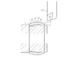
- the inner diameter surface 15 of the cage 8 may be referred to as an end A corresponding to the opening side of the outer ring 3 from the axial center 17 (hereinafter, simply referred to as an end A corresponding to the opening side).
- a certain range H1 and a range H2 of an end B corresponding to the back side of the outer ring 3 from the axial center 17 (hereinafter, simply referred to as an end B corresponding to the back side).
- the degree (surface roughness) is different.
- the spherical surface roughness in the range H1 is made rougher than the spherical surface roughness in the range H2.
- the surface roughness of the range H1 is R1
- the surface roughness of the range H2 is R2
- the surface roughness R2 in the range H2 is set to Ra 0.8 or less.
- the outer diameter surface 14 of the cage 8 may be referred to as an end C corresponding to the back side of the outer ring 3 from the axial center 18 (hereinafter, simply referred to as an end C corresponding to the back side).
- the spherical surface roughness The degree (surface roughness) is different.
- the spherical surface roughness in the range H3 is made rougher than the spherical surface roughness in the range H4.
- the surface roughness of the range H3 is R3 and the surface roughness of the range H4 is R4, R4 ⁇ R3 ⁇ 2 ⁇ R4. Further, the surface roughness R4 in the range H4 is set to Ra 0.8 or less.
- the surface roughness is a centerline average roughness, and the roughness curve is folded back from the centerline, and the area obtained by the roughness curve and the centerline is measured length.
- the divided value is expressed in micrometers ( ⁇ m).
- the cutting (grinding) of the inner diameter surface 15 of the cage 8 is performed by moving the blade of the tool 19 from the end B side corresponding to the inner side of the inner diameter surface 15 to the opening side as shown by an arrow. Move to the corresponding end A side.
- the surface roughness in the range H1 from the axial center 17 to the end A side may be rougher than the surface roughness in the range H2 from the axial center 17 to the end B, so the cutting tool in the range H1 Finishing with can be finished rough.
- the cutting (grinding) of the outer diameter surface 14 of the cage 8 is performed by moving the blade of the tool 20 from the end D side corresponding to the opening side of the outer diameter surface 14 as shown by an arrow. It moves to the end C side corresponding to the side.
- the surface roughness of the range H3 from the axial center 18 to the end C side may be rougher than the surface roughness of the range H4 from the axial center 18 to the end D side.
- the finishing process by the cutting tool in the range H3 can be roughly finished.
- the range H1 on the end A side corresponding to the opening side from the axial center 17 of the inner diameter surface 15 of the cage 8 and the end C side corresponding to the rear side from the axial center 18 of the outer diameter surface 14 are shown.
- the finishing process by the cutting tool can be roughly finished, so that the wear of the cutting tool can be reduced. Thereby, the lifetime of the cutting tool can be extended, and the production cost can be reduced.
- the spherical surface roughness in the range H2 on the end B side corresponding to the back side from the axial center 17 of the inner diameter surface 15 is the end corresponding to the opening side from the center 17 in the axial direction. You may make it rougher than the spherical surface roughness in the range H1 on the A side. However, since the track groove 2 of the outer ring 3 opens to the inlet side (opening side), the spherical surface roughness in the range H1 on the end A side corresponding to the opening side from the axial center 17 is set to the axial center 17.
- the roughness of the spherical surface roughness in the range H2 on the end B side corresponding to the rear side from the rear side has less influence on the function of the constant velocity universal joint. Therefore, as in the embodiment described with reference to FIG. 1, it is preferable that the spherical surface roughness in the range H ⁇ b> 1 on the end A side from the axial center 17 is made rougher than the spherical surface roughness in the range H ⁇ b> 2.
- the spherical surface roughness in the range H4 on the end D side corresponding to the opening side from the axial center 18 is the end C side corresponding to the back side from the axial center 18. It may be made rougher than the spherical surface roughness in the range H3. However, in the same manner as described above, since the influence on the function of the constant velocity universal joint is reduced, the spherical surface roughness in the range H3 on the end C side corresponding to the back side from the axial center 18 of the outer diameter surface 14 is reduced. The degree is preferably made rougher than the spherical surface roughness in the range H4 on the end D side corresponding to the opening side from the axial center 18.
- the spherical surface roughness on the end A side corresponding to the opening side from the axial center 17 of the inner diameter surface 15 is R1
- the spherical surface on the end B side corresponding to the inner side from the axial center 17 of the inner diameter surface 15 is R1.
- the spherical surface roughness on the end C side corresponding to the rear side from the axial center 18 of the outer diameter surface 14 of the cage 8 is R3
- the end corresponding to the opening side from the axial center 17 of the outer diameter surface 14 is defined as R3.
- the degree to Ra 0.8 or less the influence on the function of the constant velocity universal joint can be extremely reduced.
- a bar field type (BJ) is shown as the constant velocity universal joint, but other fixed type constant velocity universal joints such as an undercut free type (UJ) may be used.
- the number of balls 7 can be arbitrarily set. In particular, the number of balls 7 can be set in the range of 3 to 8, but is not limited thereto.
- the hardening process may be a process such as carburizing and quenching other than induction hardening.
- only one of the inner diameter surface 15 and the outer diameter surface 14 of the cage 8 is a spherical surface on each of the end side corresponding to the opening side and the end side corresponding to the back side with the axial center as a boundary.
- the roughness may be different.
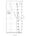
- FIG. 4 shows the relationship between the number of cage inner diameter surfaces that can be processed by one cutting tool and the surface roughness.
- ⁇ indicates the surface roughness at the axial center 17 of the inner diameter surface 15
- ⁇ indicates the surface roughness on the end B side corresponding to the inner side of the inner diameter surface 15
- ⁇ indicates the inner surface 15.
- the surface roughness on the end A side corresponding to the inlet side (opening side) is shown.
- the tool life is reached when the surface roughness on the end A side corresponding to the opening side cannot be secured to the same surface roughness as the end B side or axial center corresponding to the back side.
- the tool life is, for example, The number of processes can be extended to about 1000.
- the outer diameter surface 14 of the cage 8 is the same as the inner diameter surface 15 by applying the configuration of the present invention.
- the tool life can be extended.
Landscapes
- Engineering & Computer Science (AREA)
- General Engineering & Computer Science (AREA)
- Mechanical Engineering (AREA)
- Rolling Contact Bearings (AREA)
Abstract
Description
6 内輪
7 ボール
8 ケージ
14 外径面
15 内径面
16 ポケット
17 軸方向中央
18 軸方向中央
A 外輪の開口側に対応する端部
B 外輪の奥側に対応する端部
C 外輪の奥側に対応する端部
D 外輪の開口側に対応する端部
Claims (8)
- 外側継手部材に案内される外径面と、内側継手部材に案内される内径面と、前記外側継手部材と前記内側継手部材との間に配設される複数のボールを収容するポケットを備えた等速自在継手用ケージにおいて、
前記内径面の軸方向中央から外側継手部材の開口側に対応する端部側の球面面粗度と、前記内径面の軸方向中央から外側継手部材の奥側に対応する端部側の球面面粗度を相違させたことを特徴とする等速自在継手用ケージ。 - 前記内径面の軸方向中央から外側継手部材の開口側に対応する端部側の球面面粗度を、前記内径面の軸方向中央から外側継手部材の奥側に対応する端部側の球面面粗度よりも粗くした請求項1に記載の等速自在継手用ケージ。
- 前記内径面の軸方向中央から外側継手部材の開口側に対応する端部側の球面面粗度をR1とし、前記内径面の軸方向中央から外側継手部材の奥側に対応する端部側の球面面粗度をR2としたときに、R2<R1<2×R2となるようにした請求項2に記載の等速自在継手用ケージ。
- 前記内径面の軸方向中央から外側継手部材の奥側に対応する端部側の球面面粗度がRa0.8以下である請求項3に記載の等速自在継手用ケージ。
- 外側継手部材に案内される外径面と、内側継手部材に案内される内径面と、前記外側継手部材と前記内側継手部材との間に配設される複数のボールを収容するポケットを備えた等速自在継手用ケージにおいて、
前記外径面の軸方向中央から外側継手部材の奥側に対応する端部側の球面面粗度と、前記外径面の軸方向中央から外側継手部材の開口側に対応する端部側の球面面粗度を相違させたことを特徴とする等速自在継手用ケージ。 - 前記外径面の軸方向中央から外側継手部材の奥側に対応する端部側の球面面粗度を、前記外径面の軸方向中央から外側継手部材の開口側に対応する端部側の球面面粗度よりも粗くした請求項5に記載の等速自在継手用ケージ。
- 前記外径面の軸方向中央から外側継手部材の奥側に対応する端部側の球面面粗度をR3とし、前記外径面の軸方向中央から外側継手部材の開口側に対応する端部側の球面面粗度をR4としたときに、R4<R3<2×R4となるようにした請求項6に記載の等速自在継手用ケージ。
- 前記外径面の軸方向中央から外側継手部材の開口側に対応する端部側の球面面粗度がRa0.8以下である請求項7に記載の等速自在継手用ケージ。
Priority Applications (3)
| Application Number | Priority Date | Filing Date | Title |
|---|---|---|---|
| US12/864,732 US8313387B2 (en) | 2008-01-30 | 2009-01-05 | Cage for constant velocity universal joint |
| EP09705154.4A EP2246583B1 (en) | 2008-01-30 | 2009-01-05 | Cage for constant velocity universal joint |
| CN2009801024496A CN101918727B (zh) | 2008-01-30 | 2009-01-05 | 等速万向接头用保持架 |
Applications Claiming Priority (2)
| Application Number | Priority Date | Filing Date | Title |
|---|---|---|---|
| JP2008019491A JP5202974B2 (ja) | 2008-01-30 | 2008-01-30 | 等速自在継手用ケージ |
| JP2008-019491 | 2008-01-30 |
Publications (1)
| Publication Number | Publication Date |
|---|---|
| WO2009096200A1 true WO2009096200A1 (ja) | 2009-08-06 |
Family
ID=40912553
Family Applications (1)
| Application Number | Title | Priority Date | Filing Date |
|---|---|---|---|
| PCT/JP2009/050001 Ceased WO2009096200A1 (ja) | 2008-01-30 | 2009-01-05 | 等速自在継手用ケージ |
Country Status (5)
| Country | Link |
|---|---|
| US (1) | US8313387B2 (ja) |
| EP (1) | EP2246583B1 (ja) |
| JP (1) | JP5202974B2 (ja) |
| CN (1) | CN101918727B (ja) |
| WO (1) | WO2009096200A1 (ja) |
Citations (4)
| Publication number | Priority date | Publication date | Assignee | Title |
|---|---|---|---|---|
| JPH07310752A (ja) * | 1994-05-13 | 1995-11-28 | Toyota Motor Corp | 等速自在継手の内輪およびその製造方法 |
| JP2002188653A (ja) | 2000-12-20 | 2002-07-05 | Ntn Corp | 等速自在継手 |
| JP2006214540A (ja) * | 2005-02-04 | 2006-08-17 | Ntn Corp | 摺動式等速自在継手 |
| JP2007232033A (ja) * | 2006-02-28 | 2007-09-13 | Ntn Corp | 固定式等速自在継手及びその製造方法 |
Family Cites Families (3)
| Publication number | Priority date | Publication date | Assignee | Title |
|---|---|---|---|---|
| US4834400A (en) * | 1988-03-15 | 1989-05-30 | University Of New Mexico | Differential surface roughness dynamic seals and bearings |
| US4973068A (en) * | 1988-03-15 | 1990-11-27 | University Of New Mexico | Differential surface roughness dynamic seals and bearings |
| US5586826A (en) * | 1994-12-19 | 1996-12-24 | Skf Sverige Ab | Roller bearing provided with roller skew control and long life characteristics |
-
2008
- 2008-01-30 JP JP2008019491A patent/JP5202974B2/ja not_active Expired - Fee Related
-
2009
- 2009-01-05 CN CN2009801024496A patent/CN101918727B/zh not_active Expired - Fee Related
- 2009-01-05 WO PCT/JP2009/050001 patent/WO2009096200A1/ja not_active Ceased
- 2009-01-05 US US12/864,732 patent/US8313387B2/en not_active Expired - Fee Related
- 2009-01-05 EP EP09705154.4A patent/EP2246583B1/en not_active Not-in-force
Patent Citations (4)
| Publication number | Priority date | Publication date | Assignee | Title |
|---|---|---|---|---|
| JPH07310752A (ja) * | 1994-05-13 | 1995-11-28 | Toyota Motor Corp | 等速自在継手の内輪およびその製造方法 |
| JP2002188653A (ja) | 2000-12-20 | 2002-07-05 | Ntn Corp | 等速自在継手 |
| JP2006214540A (ja) * | 2005-02-04 | 2006-08-17 | Ntn Corp | 摺動式等速自在継手 |
| JP2007232033A (ja) * | 2006-02-28 | 2007-09-13 | Ntn Corp | 固定式等速自在継手及びその製造方法 |
Non-Patent Citations (1)
| Title |
|---|
| See also references of EP2246583A4 * |
Also Published As
| Publication number | Publication date |
|---|---|
| US20110045914A1 (en) | 2011-02-24 |
| CN101918727B (zh) | 2013-03-06 |
| JP5202974B2 (ja) | 2013-06-05 |
| EP2246583B1 (en) | 2013-05-22 |
| JP2009180285A (ja) | 2009-08-13 |
| EP2246583A1 (en) | 2010-11-03 |
| EP2246583A4 (en) | 2012-05-09 |
| CN101918727A (zh) | 2010-12-15 |
| US8313387B2 (en) | 2012-11-20 |
Similar Documents
| Publication | Publication Date | Title |
|---|---|---|
| JP5882172B2 (ja) | トルク伝達装置、トルクを伝達するために2つの機能領域を有する構成部分を製造するための方法、及びジョイント軸 | |
| WO2011043268A1 (ja) | 固定式等速自在継手 | |
| JP2008174208A (ja) | 車輪用軸受装置のハブ輪およびその製造方法 | |
| JP5202975B2 (ja) | 等速自在継手用内側継手部材、その製造方法、及び等速自在継手 | |
| JP5202974B2 (ja) | 等速自在継手用ケージ | |
| JP4813286B2 (ja) | 等速自在継手用外側継手部材 | |
| JP2010043691A (ja) | 等速自在継手およびその製造方法 | |
| JP2009191902A (ja) | 車輪用軸受装置 | |
| JP2009191901A (ja) | 等速自在継手のケージ、プロペラシャフトアッセンブリー、およびドライブシャフトアッセンブリー | |
| JP7513831B2 (ja) | カウンタートラックジョイントおよびカウンタートラックジョイントの製造方法 | |
| JP4795271B2 (ja) | 等速自在継手用ケージ及びその組み付け方法 | |
| JP5085465B2 (ja) | トリポード型等速自在継手 | |
| JP5165488B2 (ja) | 等速自在継手の内側継手部材 | |
| JP2009191909A (ja) | 車輪用軸受装置 | |
| JP2010260144A (ja) | シール面加工方法、等速自在継手用外側継手部材、及び車輪用軸受装置 | |
| JP2009174660A (ja) | 等速自在継手のケージ、プロペラシャフトアッセンブリー、およびドライブシャフトアッセンブリー | |
| JP2009185878A (ja) | 等速自在継手及びシャフトアッセンブリ | |
| JP2010112505A (ja) | ダブルオフセット型等速自在継手 | |
| JP2007100801A (ja) | 等速自在継手用ケージおよび等速自在継手 | |
| JP2007064265A (ja) | 等速自在継手及びその内方部材 | |
| JP2008075779A (ja) | 等速自在継手用ケージおよび等速自在継手用ケージの製造方法 | |
| JP2007315578A (ja) | 等速自在継手用ケージ | |
| JP2010019344A (ja) | 摺動式等速自在継手 | |
| JP2009191905A (ja) | 車輪用軸受装置 | |
| JP2010025317A (ja) | 等速自在継手 |
Legal Events
| Date | Code | Title | Description |
|---|---|---|---|
| WWE | Wipo information: entry into national phase |
Ref document number: 200980102449.6 Country of ref document: CN |
|
| 121 | Ep: the epo has been informed by wipo that ep was designated in this application |
Ref document number: 09705154 Country of ref document: EP Kind code of ref document: A1 |
|
| WWE | Wipo information: entry into national phase |
Ref document number: 12864732 Country of ref document: US |
|
| NENP | Non-entry into the national phase |
Ref country code: DE |
|
| WWE | Wipo information: entry into national phase |
Ref document number: 5333/CHENP/2010 Country of ref document: IN Ref document number: 2009705154 Country of ref document: EP |