WO2009096210A1 - エンジン - Google Patents
エンジン Download PDFInfo
- Publication number
- WO2009096210A1 WO2009096210A1 PCT/JP2009/050174 JP2009050174W WO2009096210A1 WO 2009096210 A1 WO2009096210 A1 WO 2009096210A1 JP 2009050174 W JP2009050174 W JP 2009050174W WO 2009096210 A1 WO2009096210 A1 WO 2009096210A1
- Authority
- WO
- WIPO (PCT)
- Prior art keywords
- engine
- reduced
- fuel injection
- combustion chamber
- cylinder
- Prior art date
- Legal status (The legal status is an assumption and is not a legal conclusion. Google has not performed a legal analysis and makes no representation as to the accuracy of the status listed.)
- Ceased
Links
Images


Classifications
-
- F—MECHANICAL ENGINEERING; LIGHTING; HEATING; WEAPONS; BLASTING
- F02—COMBUSTION ENGINES; HOT-GAS OR COMBUSTION-PRODUCT ENGINE PLANTS
- F02D—CONTROLLING COMBUSTION ENGINES
- F02D41/00—Electrical control of supply of combustible mixture or its constituents
- F02D41/02—Circuit arrangements for generating control signals
- F02D41/04—Introducing corrections for particular operating conditions
- F02D41/06—Introducing corrections for particular operating conditions for engine starting or warming up
- F02D41/062—Introducing corrections for particular operating conditions for engine starting or warming up for starting
- F02D41/064—Introducing corrections for particular operating conditions for engine starting or warming up for starting at cold start
-
- F—MECHANICAL ENGINEERING; LIGHTING; HEATING; WEAPONS; BLASTING
- F02—COMBUSTION ENGINES; HOT-GAS OR COMBUSTION-PRODUCT ENGINE PLANTS
- F02D—CONTROLLING COMBUSTION ENGINES
- F02D17/00—Controlling engines by cutting out individual cylinders; Rendering engines inoperative or idling
-
- F—MECHANICAL ENGINEERING; LIGHTING; HEATING; WEAPONS; BLASTING
- F02—COMBUSTION ENGINES; HOT-GAS OR COMBUSTION-PRODUCT ENGINE PLANTS
- F02D—CONTROLLING COMBUSTION ENGINES
- F02D41/00—Electrical control of supply of combustible mixture or its constituents
- F02D41/008—Controlling each cylinder individually
- F02D41/0087—Selective cylinder activation, i.e. partial cylinder operation
-
- F—MECHANICAL ENGINEERING; LIGHTING; HEATING; WEAPONS; BLASTING
- F02—COMBUSTION ENGINES; HOT-GAS OR COMBUSTION-PRODUCT ENGINE PLANTS
- F02D—CONTROLLING COMBUSTION ENGINES
- F02D41/00—Electrical control of supply of combustible mixture or its constituents
- F02D41/30—Controlling fuel injection
- F02D41/38—Controlling fuel injection of the high pressure type
- F02D41/3809—Common rail control systems
- F02D41/3827—Common rail control systems for diesel engines
-
- F—MECHANICAL ENGINEERING; LIGHTING; HEATING; WEAPONS; BLASTING
- F02—COMBUSTION ENGINES; HOT-GAS OR COMBUSTION-PRODUCT ENGINE PLANTS
- F02D—CONTROLLING COMBUSTION ENGINES
- F02D2200/00—Input parameters for engine control
- F02D2200/02—Input parameters for engine control the parameters being related to the engine
- F02D2200/021—Engine temperature
-
- F—MECHANICAL ENGINEERING; LIGHTING; HEATING; WEAPONS; BLASTING
- F02—COMBUSTION ENGINES; HOT-GAS OR COMBUSTION-PRODUCT ENGINE PLANTS
- F02D—CONTROLLING COMBUSTION ENGINES
- F02D2200/00—Input parameters for engine control
- F02D2200/02—Input parameters for engine control the parameters being related to the engine
- F02D2200/023—Temperature of lubricating oil or working fluid
-
- F—MECHANICAL ENGINEERING; LIGHTING; HEATING; WEAPONS; BLASTING
- F02—COMBUSTION ENGINES; HOT-GAS OR COMBUSTION-PRODUCT ENGINE PLANTS
- F02D—CONTROLLING COMBUSTION ENGINES
- F02D2200/00—Input parameters for engine control
- F02D2200/02—Input parameters for engine control the parameters being related to the engine
- F02D2200/04—Engine intake system parameters
- F02D2200/0406—Intake manifold pressure
-
- F—MECHANICAL ENGINEERING; LIGHTING; HEATING; WEAPONS; BLASTING
- F02—COMBUSTION ENGINES; HOT-GAS OR COMBUSTION-PRODUCT ENGINE PLANTS
- F02D—CONTROLLING COMBUSTION ENGINES
- F02D2200/00—Input parameters for engine control
- F02D2200/02—Input parameters for engine control the parameters being related to the engine
- F02D2200/06—Fuel or fuel supply system parameters
- F02D2200/0602—Fuel pressure
- F02D2200/0604—Estimation of fuel pressure
-
- F—MECHANICAL ENGINEERING; LIGHTING; HEATING; WEAPONS; BLASTING
- F02—COMBUSTION ENGINES; HOT-GAS OR COMBUSTION-PRODUCT ENGINE PLANTS
- F02D—CONTROLLING COMBUSTION ENGINES
- F02D41/00—Electrical control of supply of combustible mixture or its constituents
- F02D41/02—Circuit arrangements for generating control signals
- F02D41/04—Introducing corrections for particular operating conditions
- F02D41/06—Introducing corrections for particular operating conditions for engine starting or warming up
- F02D41/068—Introducing corrections for particular operating conditions for engine starting or warming up for warming-up
-
- F—MECHANICAL ENGINEERING; LIGHTING; HEATING; WEAPONS; BLASTING
- F02—COMBUSTION ENGINES; HOT-GAS OR COMBUSTION-PRODUCT ENGINE PLANTS
- F02D—CONTROLLING COMBUSTION ENGINES
- F02D41/00—Electrical control of supply of combustible mixture or its constituents
- F02D41/02—Circuit arrangements for generating control signals
- F02D41/04—Introducing corrections for particular operating conditions
- F02D41/10—Introducing corrections for particular operating conditions for acceleration
- F02D41/105—Introducing corrections for particular operating conditions for acceleration using asynchronous injection
-
- F—MECHANICAL ENGINEERING; LIGHTING; HEATING; WEAPONS; BLASTING
- F02—COMBUSTION ENGINES; HOT-GAS OR COMBUSTION-PRODUCT ENGINE PLANTS
- F02D—CONTROLLING COMBUSTION ENGINES
- F02D41/00—Electrical control of supply of combustible mixture or its constituents
- F02D41/02—Circuit arrangements for generating control signals
- F02D41/14—Introducing closed-loop corrections
- F02D41/1497—With detection of the mechanical response of the engine
- F02D41/1498—With detection of the mechanical response of the engine measuring engine roughness
-
- F—MECHANICAL ENGINEERING; LIGHTING; HEATING; WEAPONS; BLASTING
- F02—COMBUSTION ENGINES; HOT-GAS OR COMBUSTION-PRODUCT ENGINE PLANTS
- F02D—CONTROLLING COMBUSTION ENGINES
- F02D41/00—Electrical control of supply of combustible mixture or its constituents
- F02D41/02—Circuit arrangements for generating control signals
- F02D41/14—Introducing closed-loop corrections
- F02D41/16—Introducing closed-loop corrections for idling
-
- F—MECHANICAL ENGINEERING; LIGHTING; HEATING; WEAPONS; BLASTING
- F02—COMBUSTION ENGINES; HOT-GAS OR COMBUSTION-PRODUCT ENGINE PLANTS
- F02D—CONTROLLING COMBUSTION ENGINES
- F02D41/00—Electrical control of supply of combustible mixture or its constituents
- F02D41/30—Controlling fuel injection
- F02D41/3011—Controlling fuel injection according to or using specific or several modes of combustion
- F02D41/3064—Controlling fuel injection according to or using specific or several modes of combustion with special control during transition between modes
Definitions
- the engine of the present invention includes a plurality of cylinders, a fuel injection device that injects fuel into each of the cylinders, a combustion chamber temperature calculation means that calculates a combustion chamber temperature, and a fuel injection amount that are all calculated by the fuel injection device.
- the normal operation is performed if the combustion chamber temperature calculated by the combustion chamber temperature calculating means is in an extremely low temperature range, and the reduced cylinder operation is performed if the fuel injection amount becomes smaller than a predetermined amount in the normal operation.
- the ECU 100 is connected to the engine coolant temperature sensor 21, the engine lubricating oil temperature sensor 22, the engine speed sensor 23, the air pressure sensor 24, the cell motor 25, the key switch 26, and the injector 16. .
- the ECU 100 replaces the combustion chamber temperature, which is difficult to obtain directly, with the engine coolant temperature TW or the engine lubricating oil temperature TL.
- An engine coolant temperature sensor 21 as a combustion chamber temperature calculation means is provided in the water jacket 11 and detects an engine coolant temperature TW as a combustion chamber temperature.
- An engine lubricating oil temperature sensor 22 as a combustion chamber temperature calculating means is provided in an oil tank (not shown) and detects an engine lubricating oil temperature TL as a combustion chamber temperature.
- the engine speed sensor 23 is provided close to the flywheel 13 fixed to the piston 10 and detects the engine speed N.
- the air pressure sensor 24 is provided in the air supply manifold 7 and detects the air pressure Pb.
- the reduced-cylinder operation is an operation in which the ECU 100 stops fuel injection for the specific cylinders 6a, 6b, and 6c.
- the cylinders 6a, 6b, and 6c to be deactivated are not limited.
- the normal operation is an operation in which a predetermined amount of fuel is injected at the most efficient timing in all the cylinders 6a, 6b, 6c, 6d, 6e, and 6f.
- the start mode is that the ECU 100 drives the diesel engine 1 by driving the cell motor 25 and fuel injection.
- the idle operation mode is that the ECU 100 drives the diesel engine 1 only by fuel injection without driving the cell motor 25.
- the stand-by for the reduced-cylinder operation refers to a state in which the reduced-cylinder operation is started when the combustion chamber temperature reaches a low temperature range or when a predetermined requirement is satisfied, and is actually a normal operation.
- Reing to reduced-cylinder operation refers to starting reduced-cylinder operation from a reduced-cylinder operation standby state.
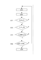
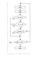
- Embodiment 1 The engine start control which is Embodiment 1 is demonstrated using FIG.
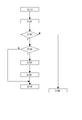
- the ECU 100 is activated by starting the engine (S110).
- the ECU 100 detects the engine coolant temperature TW by the engine coolant temperature sensor 21 (S120), and determines whether the engine is started at a very low temperature or at a low temperature based on the engine coolant temperature TW (S130). .
- the ECU 100 performs normal operation if it is not a cryogenic start or a cold start (S180), and determines if it is a cryogenic start if it is a cryogenic start or a cold start (S140).
- the ECU 100 performs a reduced-cylinder operation if it is a low temperature start (S170), and calculates a reduced-cylinder operation standby time TRCL_STBY as a predetermined time if it is a very low temperature start (S150). After waiting for the reduced cylinder operation during the operation standby time TRCL_STBY (S160), the reduced cylinder operation is started (S170).
- the TW map 40 will be described with reference to FIG.
- the TW map 40 is stored in the ECU 100 in advance.
- a reduced cylinder operation standby time TRCL_STBY (s), which is a time period during which it is assumed that the reduced cylinder operation can be performed from the low temperature start, is defined. That is, the ECU 100 can calculate the reduced cylinder operation standby time TRCL_STBY based on the engine coolant temperature TW using the TW map 40.
- the reduced cylinder operation can be started when the reduced cylinder operation waiting time TRCL_STBY that is assumed to be low in the temperature of the combustion chamber during standby of the reduced cylinder operation in the cryogenic temperature range. Therefore, if the combustion chamber temperature becomes low, the blue and white smoke of the diesel engine 1 can be effectively reduced.
- the correlation between the engine coolant temperature TW and the start mode in the engine start control according to the first embodiment. explain.
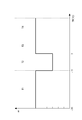
- the ECU 100 waits for the reduced-cylinder operation when the engine coolant temperature TW is in the extremely low temperature region T1, that is, performs normal operation, and starts the reduced-cylinder operation when the engine coolant temperature TW reaches the low temperature region T2.
- the ECU 100 performs normal operation when the engine coolant temperature TW reaches the normal temperature region T3 or the warm state region T4.
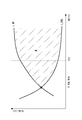
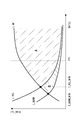
- the misfire limit line L_MF is the minimum fuel injection amount at which the diesel engine 1 misfires.
- the combustion chamber 9 in the diesel engine 1 is deprived of a large amount of heat by the evaporation heat of the fuel. This latent heat of vaporization increases depending on the fuel injection amount. Therefore, even if the fuel injection quantity Q is the same, the diesel engine 1 is liable to misfire because the air-fuel mixture cannot cause a combustion reaction as the engine coolant temperature TW becomes lower. Therefore, in the diesel engine 1, as indicated by the misfire limit line L_MF, the minimum fuel injection amount causing misfire decreases as the engine coolant temperature TW decreases.
- the horizontal axis is time t (s)
- the upper stage of the vertical axis is the engine speed N (rpm)
- the lower stage is the fuel injection amount Q (mm 3 / st)
- the upper one-dot chain line indicates the target idle speed Nm_ID (rpm)
- the lower one-dot chain line indicates the misfire limit line L_MF described above.
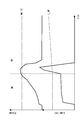
- the engine start control is started by reduced-cylinder operation even when the engine coolant temperature TW is in the extremely low temperature region T1.
- the engine coolant temperature TW is in the extremely low temperature region T1 at the moment when the diesel engine 1 enters the idle operation mode M2 by the reduced-cylinder operation from the start mode M1, the fuel necessary for maintaining the idle rotation
- the injection quantity Q increases extremely, and the engine stalls due to misfire.
- the low temperature start limit of the diesel engine 1 of Embodiment 1 will be described using the graph of FIG. 7 (the horizontal axis is the engine coolant temperature TW (° C.) and the vertical axis is the fuel injection amount Q (mm 3 / st)).
- FIG. 7 is the same as FIG. 5 with respect to the region A, the misfire limit line L_MF, and the fuel injection amount limit line (when the number of cylinders is reduced), and thus the description thereof is omitted.
- the engine start control according to the first embodiment waits for the reduced-cylinder operation when the engine coolant temperature TW is at the extremely low temperature T1.
- the fuel injection amount Q increases as compared to the normal operation.
- the fuel injection amount limit line (normal time) L_NORM decreases from the fuel injection amount limit line (reduction cylinder) L_RCL.
- the start limit region for normal operation is expanded to region B in addition to region A.
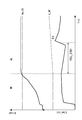
- the horizontal axis is the time t (s)
- the upper stage of the vertical axis is the engine speed N (rpm)
- the lower stage is the fuel injection amount Q (mm 3 / st)).
- the control behavior will be described in detail.
- the target idle speed Nm_ID (rpm) and the misfire limit line L_MF are the same as those in FIG.
- the fuel injection amount Q of the diesel engine 1 is smaller than that during the reduced-cylinder operation because the reduced-cylinder operation is waited for the reduced-cylinder operation standby time TRCL_STBY. That is, the diesel engine 1 can be reliably started even in the cryogenic region T1. Further, the reduced cylinder operation can be started after the friction of the diesel engine 1 is reduced. Therefore, the misfire margin (Q ⁇ in the figure) of the diesel engine 1 can be secured at the start of the reduced cylinder operation.
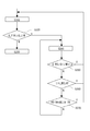
- the engine start control which is Embodiment 2 is demonstrated using FIG.
- the ECU 100 is activated by starting the engine (S210).
- the ECU 100 detects the engine coolant temperature TW (S220), and determines whether or not it is a cryogenic start or a cold start (S230).
- the ECU 100 performs a normal operation if it is not a cryogenic start or a cold start (S300), and determines if it is a cryogenic start if it is a cryogenic start or a cold start (S240).
- S250 if the ECU 100 starts at a very low temperature, the ECU 100 waits for a reduced-cylinder operation (S250).
- the ECU 100 calculates a normal fuel injection amount Q_NORM for normal operation, and calculates an estimated fuel injection amount Q_RCL for reduced cylinder operation for reduced cylinder operation based on the normal fuel injection amount Q_NORM. (S260). Further, the ECU 100 calculates the misfire limit injection amount Q_MF based on the engine coolant temperature TW, and determines whether or not the estimated fuel injection amount Q_RCL at the time of reduced cylinder is smaller than the misfire limit injection amount Q_MF (S270). Here, ECU 100 waits for reduced-cylinder operation if not small in S270 (S250).
- the estimated fuel injection amount Q_RCL at the time of cylinder reduction is smaller than the misfire limit injection quantity Q_MF while waiting for the cylinder reduction operation at an extremely low temperature, it is possible to return to the cylinder reduction operation. That is, the blue and white smoke of the diesel engine 1 can be effectively reduced.
- the combustion chamber temperature which is difficult to obtain directly, is replaced by the estimated fuel injection amount Q_RCL at the time of reduced cylinder assumed at the time of reduced cylinder operation. Therefore, the diesel engine 1 can return to the reduced-cylinder operation at an appropriate timing.
- the fuel injection amount during the reduced cylinder operation can be limited to be equal to or less than the maximum fuel injection amount Q_FULL during the normal operation based on the supply air pressure Pb. Therefore, generation of black smoke in the diesel engine 1 can be prevented.
- the engine start control according to the third embodiment will be described with reference to FIG.
- the third embodiment is a control in which steps S250 to S290 of the second embodiment are changed. If the ECU 100 starts at a very low temperature, the ECU 100 waits for a reduced-cylinder operation (S250), and calculates an estimated fuel injection amount Q_RCL during reduced-cylinder (S260).
- ECU100 determines whether engine cooling water temperature TW is larger than predetermined temperature TW_TH (S271). Here, if it is not larger in S271, the reduced cylinder operation is waited (S240). On the other hand, the ECU 100 determines whether or not the engine lubricating oil temperature TL is higher than a predetermined temperature TL_TH (S272). Here, if it is not large in S272, the reduced cylinder operation is waited (S250). On the other hand, the ECU 100 determines whether or not the normal fuel injection amount Q_NORM is smaller than the predetermined amount Q_TH (S273). Here, if it is not small in S273, the reduced-cylinder operation is waited (S250). On the other hand, if all conditions are satisfied in S271, S272, and S273, ECU 100 performs a reduced-cylinder operation through S280 (S290).
- the diesel engine 1 cannot return to the reduced cylinder operation unless the engine coolant temperature TW, the engine lubricating oil temperature TL, and the normal fuel injection amount Q_NORM all satisfy the predetermined conditions.
- the engine start control according to the fourth embodiment will be described with reference to FIG.
- the fourth embodiment is a control in which steps S250 to S290 of the second embodiment are changed. If the ECU 100 starts at a very low temperature, the ECU 100 waits for a reduced-cylinder operation (S250), and calculates an estimated fuel injection amount Q_RCL during reduced-cylinder (S260).
- ECU100 determines whether engine cooling water temperature TW is larger than predetermined temperature TW_TH (S275). Here, if it is larger in S275, the reduced-cylinder operation is performed through S280 (S290). On the other hand, the ECU 100 determines whether or not the engine lubricating oil temperature TL is higher than a predetermined temperature TL_TH (S276). Here, if it is larger in S276, the reduced-cylinder operation is performed through S280 (S290). On the other hand, the ECU 100 determines whether or not the normal fuel injection amount Q_NORM is smaller than the predetermined amount Q_TH (S277). Here, if it is smaller in S276, the reduced-cylinder operation is performed through S280 (S290). On the other hand, if all conditions are not satisfied in S275, S276, and S277, ECU 100 waits for a reduced cylinder operation (S250).
- the diesel engine 1 can return to the reduced cylinder operation if one of the engine coolant temperature TW, the engine lubricating oil temperature TL, and the normal fuel injection amount Q_NORM satisfies a predetermined condition.
- the engine start control according to the fourth embodiment will be described with reference to FIG.
- the ECU 100 starts the reduced-cylinder operation (S310), determines whether or not the fuel injection amount Q_FIN at the time of reduced-cylinder is greater than or equal to the predetermined amount Q_LIM (S320). If not greater than the predetermined amount Q_LIM in S320, the reduced-cylinder operation is performed. The operation is continued as it is (S330).
- the ECU 100 waits for the reduced cylinder operation (S340).
- the ECU 100 determines whether or not the estimated fuel injection amount Q_RCL at the time of reduced cylinder is smaller than a value obtained by multiplying the fuel injection limit amount Q_LIM at the time of waiting for reduced cylinder operation by a predetermined rate ⁇ (S350).
- the reduced-cylinder operation is started (S310).
- the ECU 100 determines whether or not a predetermined time t_DELAY has elapsed from the time t when the reduced cylinder operation is waited (S360).
- the reduced cylinder operation is started (S310). Further, the ECU 100 has the engine coolant temperature TW increased by a predetermined temperature TW_DELTA from the engine coolant temperature TW during standby for the reduced cylinder operation. It is determined whether or not (S370). Here, if it is larger in S350, the reduced-cylinder operation is started (S310).
- ECU 100 waits for the reduced-cylinder operation (S310).
- the present invention can be used for a diesel engine that performs reduced-cylinder operation.
Landscapes
- Engineering & Computer Science (AREA)
- Chemical & Material Sciences (AREA)
- Combustion & Propulsion (AREA)
- Mechanical Engineering (AREA)
- General Engineering & Computer Science (AREA)
- Oil, Petroleum & Natural Gas (AREA)
- Electrical Control Of Air Or Fuel Supplied To Internal-Combustion Engine (AREA)
- Combined Controls Of Internal Combustion Engines (AREA)
- Output Control And Ontrol Of Special Type Engine (AREA)
Abstract
Description
クランク軸12は、コンロッド12aを介してピストン10に連結される軸であり、ピストン10の往復運動によって回転運動を行う。
ウォータージャケット11は、燃焼室9を冷却するエンジン冷却水が通過する二重構造の空間である。
燃焼室温度算出手段としてのエンジン冷却水温度センサー21は、ウォータージャケット11に設けられ、燃焼室温度としてのエンジン冷却水温度TWを検出する。
燃焼室温度算出手段としてのエンジン潤滑油温度センサー22は、オイルタンク(図示略)に設けられ、燃焼室温度としてのエンジン潤滑油温度TLを検出する。
エンジン回転数センサー23は、ピストン10に固設されるフライホイール13に近設され、エンジン回転数Nを検出する。
給気圧センサー24は、給気マニホールド7に設けられ、給気圧Pbを検出する。
低温始動とは、燃焼室温度が低温域(-10℃~0℃)であるときのエンジン始動である。
極低温始動とは、燃焼室温度が極低温域(-30℃~-10℃)であるときのエンジン始動である。
通常運転とは、全ての気筒6a・6b・6c・6d・6e・6fに最も効率の良いタイミングで所定量の燃料噴射を行う運転である。
始動モードとは、ECU100がセルモータ25の駆動及び燃料噴射によって、ディーゼルエンジン1を駆動することである。
アイドル運転モードとは、ECU100がセルモータ25の駆動を伴わず燃料噴射のみによって、ディーゼルエンジン1を駆動することである。
減筒運転の復帰とは、減筒運転待機の状態から減筒運転を開始することをいう。
図2を用いて、実施形態1であるエンジン始動制御について説明する。ECU100は、エンジン始動によって起動される(S110)。次に、ECU100は、エンジン冷却水温度センサー21によって、エンジン冷却水温度TWを検出し(S120)、エンジン冷却水温度TWに基づいて、極低温始動又は低温始動か否かを判定する(S130)。このとき、ECU100は、極低温始動又は低温始動でなければ、通常運転を行い(S180)、極低温始動又は低温始動であれば、極低温始動か否かを判定する(S140)。このとき、ECU100は、低温始動であれば、減筒運転を行い(S170)、極低温始動であれば、所定時間としての減筒運転待機時間TRCL_STBYを算出し(S150)、算出された減筒運転待機時間TRCL_STBYの間において減筒運転を待機した後に(S160)、減筒運転を開始する(S170)。
なお、図7は、領域A、失火限界線L_MF、及び燃料噴射量限界線(減筒時)L_RCLについては、図5と同様であるため、説明を省略する。
実施形態1のエンジン始動制御は、エンジン冷却水温度TWが極低温T1にあれば、減筒運転を待機する。ここで、減筒運転とは、通常運転に比較して、燃料噴射量Qが増加する。そのため、エンジン冷却水温度TWが低くなるに従い、燃料噴射量限界線(通常時)L_NORMは、燃料噴射量限界線(減筒時)L_RCLより減少する。このようにして、通常運転の始動限界領域は、領域Aに加えて領域Bまで拡張される。
図9を用いて、実施形態2であるエンジン始動制御について説明する。ECU100は、エンジン始動によって起動される(S210)。ECU100は、エンジン冷却水温度TWを検出し(S220)、極低温始動又は低温始動か否かを判定する(S230)。このとき、ECU100は、極低温始動又は低温始動でなければ、通常運転を行い(S300)、極低温始動又は低温始動であれば、極低温始動か否かを判定する(S240)。次に、ECU100は、S240において、極低温始動であれば、減筒運転を待機する(S250)。
Claims (3)
- 複数の気筒と、
前記各気筒に燃料を噴射する燃料噴射装置と、
燃焼室温度を算出する燃焼室温度算出手段と、
前記燃料噴射装置によって全ての気筒に燃料を噴射する通常運転、或いは前記燃料噴射装置によって特定気筒のみに燃料を噴射する減筒運転によってエンジン始動を行う制御手段と、を具備するエンジンにおいて、
前記制御手段は、エンジン始動時に、前記燃焼室温度算出手段によって算出される燃焼室温度が極低温域であれば前記通常運転を行い、前記燃焼室温度が低温域になれば前記減筒運転を行うことを特徴とするエンジン。 - 前記制御手段は、エンジン始動時に、前記通常運転を行う場合に、前記通常運転を所定期間行った後に、前記減筒運転を行うことを特徴とする請求項1記載のエンジン。
- 複数の気筒と、
前記各気筒に燃料を噴射する燃料噴射装置と、
燃焼室温度を算出する燃焼室温度算出手段と、
燃料噴射量を算出し、前記燃料噴射装置によって全ての気筒に燃料を噴射する通常運転、或いは前記燃料噴射装置によって特定気筒のみに燃料を噴射する減筒運転によってエンジン始動を行う制御手段と、を具備するエンジンにおいて、
前記制御手段は、エンジン始動時に、前記燃焼室温度算出手段によって算出される燃焼室温度が極低温域であれば前記通常運転を行い、該通常運転において燃料噴射量が所定量より小さくなれば前記減筒運転を行うことを特徴とするエンジン。
Priority Applications (3)
| Application Number | Priority Date | Filing Date | Title |
|---|---|---|---|
| EP09705781.4A EP2249015B1 (en) | 2008-01-28 | 2009-01-09 | Engine |
| US12/864,466 US20100307458A1 (en) | 2008-01-28 | 2009-01-09 | Engine |
| CN2009801033989A CN101925728B (zh) | 2008-01-28 | 2009-01-09 | 发动机 |
Applications Claiming Priority (2)
| Application Number | Priority Date | Filing Date | Title |
|---|---|---|---|
| JP2008016178A JP4897715B2 (ja) | 2008-01-28 | 2008-01-28 | ディーゼルエンジンの制御装置 |
| JP2008-016178 | 2008-01-28 |
Publications (1)
| Publication Number | Publication Date |
|---|---|
| WO2009096210A1 true WO2009096210A1 (ja) | 2009-08-06 |
Family
ID=40912563
Family Applications (1)
| Application Number | Title | Priority Date | Filing Date |
|---|---|---|---|
| PCT/JP2009/050174 Ceased WO2009096210A1 (ja) | 2008-01-28 | 2009-01-09 | エンジン |
Country Status (6)
| Country | Link |
|---|---|
| US (1) | US20100307458A1 (ja) |
| EP (1) | EP2249015B1 (ja) |
| JP (1) | JP4897715B2 (ja) |
| KR (1) | KR101150402B1 (ja) |
| CN (1) | CN101925728B (ja) |
| WO (1) | WO2009096210A1 (ja) |
Families Citing this family (6)
| Publication number | Priority date | Publication date | Assignee | Title |
|---|---|---|---|---|
| US8408176B2 (en) * | 2009-01-09 | 2013-04-02 | Ford Global Technologies, Llc | System and method for reducing hydrocarbon emissions in a gasoline direct injection engine |
| JP5924258B2 (ja) * | 2012-12-25 | 2016-05-25 | トヨタ自動車株式会社 | 燃料噴射装置の制御装置 |
| JP6332255B2 (ja) * | 2015-12-10 | 2018-05-30 | トヨタ自動車株式会社 | 内燃機関の制御装置 |
| FR3089563B1 (fr) * | 2018-12-10 | 2020-11-13 | Psa Automobiles Sa | Procede de chauffage du liquide de refroidissement d’un moteur a combustion interne apres un demarrage a froid |
| JP7385553B2 (ja) * | 2020-12-31 | 2023-11-22 | 株式会社クボタ | エンジン搭載車両 |
| CN116792238A (zh) * | 2023-06-26 | 2023-09-22 | 潍柴动力股份有限公司 | 一种发动机的断油控制方法、装置、电子设备和存储介质 |
Citations (2)
| Publication number | Priority date | Publication date | Assignee | Title |
|---|---|---|---|---|
| JPS6296752A (ja) * | 1985-10-23 | 1987-05-06 | Mazda Motor Corp | デイ−ゼルエンジンの燃料制御装置 |
| JPH07158482A (ja) * | 1993-12-06 | 1995-06-20 | Nissan Motor Co Ltd | 多気筒内燃機関の燃料噴射制御装置 |
Family Cites Families (26)
| Publication number | Priority date | Publication date | Assignee | Title |
|---|---|---|---|---|
| JPS549B2 (ja) * | 1974-06-01 | 1979-01-05 | ||
| US4393825A (en) * | 1980-12-31 | 1983-07-19 | Cummins Engine Company, Inc. | System for controlling fuel flow within an internal combustion engine |
| JPS59103940A (ja) * | 1982-12-06 | 1984-06-15 | Toyota Motor Corp | 内燃機関の始動燃料制御方法 |
| DE4445779A1 (de) * | 1994-12-21 | 1996-06-27 | Fev Motorentech Gmbh & Co Kg | Verfahren zur Steuerung einer Mehrzylinder-Brennkraftmaschine in der Kaltstart- und Warmlaufphase |
| JPH08338282A (ja) * | 1995-06-09 | 1996-12-24 | Toyota Motor Corp | 多気筒内燃機関の燃料噴射制御装置 |
| JP3454116B2 (ja) * | 1997-11-10 | 2003-10-06 | トヨタ自動車株式会社 | 車両用駆動装置 |
| US6243642B1 (en) * | 1999-03-31 | 2001-06-05 | Detroit Diesel Corporation | System and method for detecting cold engine operation |
| US6286488B1 (en) * | 1999-10-07 | 2001-09-11 | General Electric Company | Diesel engine start assist apparatus |
| JP2001227369A (ja) * | 2000-02-17 | 2001-08-24 | Honda Motor Co Ltd | 気筒休止内燃機関の制御装置 |
| JP3849395B2 (ja) * | 2000-03-14 | 2006-11-22 | いすゞ自動車株式会社 | エンジンの燃料噴射制御装置 |
| US6705277B1 (en) * | 2000-07-13 | 2004-03-16 | Caterpillar Inc | Method and apparatus for delivering multiple fuel injections to the cylinder of an engine wherein the pilot fuel injection occurs during the intake stroke |
| US6520158B1 (en) * | 2000-11-28 | 2003-02-18 | Deere & Company | Engine fuel delivery control system |
| JP2002317669A (ja) * | 2001-04-19 | 2002-10-31 | Mitsubishi Electric Corp | 内燃機関の燃料噴射制御装置 |
| EP1458958A1 (en) * | 2001-11-30 | 2004-09-22 | Delphi Technologies, Inc. | Engine cylinder deactivation to improve the performance of exhaust emission control systems |
| US7073488B2 (en) * | 2003-03-11 | 2006-07-11 | Caterpillar Inc. | Cylinder cutout strategy for engine stability |
| JP2005009364A (ja) * | 2003-06-17 | 2005-01-13 | Honda Motor Co Ltd | 多気筒内燃機関の気筒休止制御装置 |
| US7059997B2 (en) * | 2003-08-04 | 2006-06-13 | Kabushiki Kaisha Toyota Chuo Kenkyusho | Engine system with cylinder number variable engine and method for controlling the engine system |
| US7086386B2 (en) * | 2004-03-05 | 2006-08-08 | Ford Global Technologies, Llc | Engine system and method accounting for engine misfire |
| JP2006183493A (ja) * | 2004-12-27 | 2006-07-13 | Nissan Motor Co Ltd | 内燃機関の制御装置 |
| JP2006283663A (ja) * | 2005-03-31 | 2006-10-19 | Toyota Industries Corp | 内燃機関における排気ガス浄化装置 |
| JP4616818B2 (ja) * | 2006-11-16 | 2011-01-19 | ヤンマー株式会社 | 内燃機関の制御方法 |
| JP2008215231A (ja) * | 2007-03-05 | 2008-09-18 | Yanmar Co Ltd | ディーゼルエンジン |
| US7478625B1 (en) * | 2007-09-11 | 2009-01-20 | Gm Global Technology Operations, Inc. | Engine cranking system with cylinder deactivation for a direct injection engine |
| US20100050993A1 (en) * | 2008-08-29 | 2010-03-04 | Yuanping Zhao | Dynamic Cylinder Deactivation with Residual Heat Recovery |
| JP4793453B2 (ja) * | 2009-02-04 | 2011-10-12 | トヨタ自動車株式会社 | 内燃機関の制御装置 |
| US9163568B2 (en) * | 2009-10-20 | 2015-10-20 | GM Global Technology Operations LLC | Cold start systems and methods |
-
2008
- 2008-01-28 JP JP2008016178A patent/JP4897715B2/ja not_active Expired - Fee Related
-
2009
- 2009-01-09 US US12/864,466 patent/US20100307458A1/en not_active Abandoned
- 2009-01-09 CN CN2009801033989A patent/CN101925728B/zh not_active Expired - Fee Related
- 2009-01-09 KR KR1020107015132A patent/KR101150402B1/ko not_active Expired - Fee Related
- 2009-01-09 EP EP09705781.4A patent/EP2249015B1/en not_active Not-in-force
- 2009-01-09 WO PCT/JP2009/050174 patent/WO2009096210A1/ja not_active Ceased
Patent Citations (2)
| Publication number | Priority date | Publication date | Assignee | Title |
|---|---|---|---|---|
| JPS6296752A (ja) * | 1985-10-23 | 1987-05-06 | Mazda Motor Corp | デイ−ゼルエンジンの燃料制御装置 |
| JPH07158482A (ja) * | 1993-12-06 | 1995-06-20 | Nissan Motor Co Ltd | 多気筒内燃機関の燃料噴射制御装置 |
Also Published As
| Publication number | Publication date |
|---|---|
| CN101925728B (zh) | 2013-11-06 |
| EP2249015B1 (en) | 2020-09-30 |
| KR20100099266A (ko) | 2010-09-10 |
| US20100307458A1 (en) | 2010-12-09 |
| EP2249015A1 (en) | 2010-11-10 |
| CN101925728A (zh) | 2010-12-22 |
| JP4897715B2 (ja) | 2012-03-14 |
| KR101150402B1 (ko) | 2012-06-01 |
| JP2009174489A (ja) | 2009-08-06 |
| EP2249015A4 (en) | 2017-11-15 |
Similar Documents
| Publication | Publication Date | Title |
|---|---|---|
| JP5786679B2 (ja) | 圧縮自己着火式エンジンの始動制御装置 | |
| JP4506527B2 (ja) | 内燃機関の制御装置 | |
| US7581531B2 (en) | Method for operating an internal combustion engine | |
| JP4616818B2 (ja) | 内燃機関の制御方法 | |
| JP2009013921A (ja) | 内燃機関の停止始動制御装置 | |
| JP4897715B2 (ja) | ディーゼルエンジンの制御装置 | |
| JP2016109014A (ja) | エンジンの制御装置 | |
| JP2011132920A (ja) | 内燃機関の制御装置 | |
| JP5040754B2 (ja) | ディーゼルエンジンの自動停止装置 | |
| JP5842678B2 (ja) | 圧縮自己着火式エンジンの始動制御方法および装置 | |
| JP4743139B2 (ja) | 内燃機関の燃料噴射量制御装置 | |
| JP5332871B2 (ja) | 火花点火式内燃機関の燃料噴射制御装置 | |
| JP6002521B2 (ja) | 筒内噴射エンジンの制御装置 | |
| JP5831168B2 (ja) | 圧縮自己着火式エンジンの始動制御装置 | |
| JP2010065569A (ja) | 内燃機関の燃料噴射制御装置 | |
| JP4978524B2 (ja) | ディーゼルエンジンの自動停止装置 | |
| JP2009062961A (ja) | ディーゼルエンジンの制御装置 | |
| JP2016109015A (ja) | エンジンの制御装置 | |
| KR101115106B1 (ko) | 내연 기관의 제어 방법 | |
| JP5948815B2 (ja) | 圧縮自己着火式エンジンの始動制御装置 | |
| JP5512307B2 (ja) | 燃料噴射制御装置 | |
| JP2024047857A (ja) | 内燃機関の始動制御装置 | |
| JP2005201063A (ja) | 圧縮着火内燃機関の始動制御装置、及び始動制御方法 | |
| JP2022165103A (ja) | エンジンの制御装置 | |
| JP5262532B2 (ja) | ディーゼルエンジンの自動停止装置及びディーゼルエンジンの制御方法 |
Legal Events
| Date | Code | Title | Description |
|---|---|---|---|
| WWE | Wipo information: entry into national phase |
Ref document number: 200980103398.9 Country of ref document: CN |
|
| 121 | Ep: the epo has been informed by wipo that ep was designated in this application |
Ref document number: 09705781 Country of ref document: EP Kind code of ref document: A1 |
|
| ENP | Entry into the national phase |
Ref document number: 20107015132 Country of ref document: KR Kind code of ref document: A |
|
| WWE | Wipo information: entry into national phase |
Ref document number: 4959/DELNP/2010 Country of ref document: IN Ref document number: 2009705781 Country of ref document: EP |
|
| WWE | Wipo information: entry into national phase |
Ref document number: 12864466 Country of ref document: US |
|
| NENP | Non-entry into the national phase |
Ref country code: DE |