WO2009096370A1 - Appareil d'évaporation - Google Patents
Appareil d'évaporation Download PDFInfo
- Publication number
- WO2009096370A1 WO2009096370A1 PCT/JP2009/051231 JP2009051231W WO2009096370A1 WO 2009096370 A1 WO2009096370 A1 WO 2009096370A1 JP 2009051231 W JP2009051231 W JP 2009051231W WO 2009096370 A1 WO2009096370 A1 WO 2009096370A1
- Authority
- WO
- WIPO (PCT)
- Prior art keywords
- evaporation
- injection
- tower
- liquid
- spray
- Prior art date
- Legal status (The legal status is an assumption and is not a legal conclusion. Google has not performed a legal analysis and makes no representation as to the accuracy of the status listed.)
- Ceased
Links
Images

Classifications
-
- B—PERFORMING OPERATIONS; TRANSPORTING
- B01—PHYSICAL OR CHEMICAL PROCESSES OR APPARATUS IN GENERAL
- B01D—SEPARATION
- B01D1/00—Evaporating
- B01D1/16—Evaporating by spraying
-
- B—PERFORMING OPERATIONS; TRANSPORTING
- B01—PHYSICAL OR CHEMICAL PROCESSES OR APPARATUS IN GENERAL
- B01D—SEPARATION
- B01D1/00—Evaporating
- B01D1/0011—Heating features
- B01D1/0029—Use of radiation
- B01D1/0035—Solar energy
-
- B—PERFORMING OPERATIONS; TRANSPORTING
- B01—PHYSICAL OR CHEMICAL PROCESSES OR APPARATUS IN GENERAL
- B01D—SEPARATION
- B01D1/00—Evaporating
- B01D1/16—Evaporating by spraying
- B01D1/20—Sprayers
-
- B—PERFORMING OPERATIONS; TRANSPORTING
- B01—PHYSICAL OR CHEMICAL PROCESSES OR APPARATUS IN GENERAL
- B01D—SEPARATION
- B01D5/00—Condensation of vapours; Recovering volatile solvents by condensation
-
- C—CHEMISTRY; METALLURGY
- C02—TREATMENT OF WATER, WASTE WATER, SEWAGE, OR SLUDGE
- C02F—TREATMENT OF WATER, WASTE WATER, SEWAGE, OR SLUDGE
- C02F1/00—Treatment of water, waste water, or sewage
- C02F1/02—Treatment of water, waste water, or sewage by heating
- C02F1/04—Treatment of water, waste water, or sewage by heating by distillation or evaporation
- C02F1/10—Treatment of water, waste water, or sewage by heating by distillation or evaporation by direct contact with a particulate solid or with a fluid, as a heat transfer medium
- C02F1/12—Spray evaporation
-
- C—CHEMISTRY; METALLURGY
- C02—TREATMENT OF WATER, WASTE WATER, SEWAGE, OR SLUDGE
- C02F—TREATMENT OF WATER, WASTE WATER, SEWAGE, OR SLUDGE
- C02F1/00—Treatment of water, waste water, or sewage
- C02F1/02—Treatment of water, waste water, or sewage by heating
- C02F1/04—Treatment of water, waste water, or sewage by heating by distillation or evaporation
- C02F1/14—Treatment of water, waste water, or sewage by heating by distillation or evaporation using solar energy
-
- C—CHEMISTRY; METALLURGY
- C02—TREATMENT OF WATER, WASTE WATER, SEWAGE, OR SLUDGE
- C02F—TREATMENT OF WATER, WASTE WATER, SEWAGE, OR SLUDGE
- C02F2103/00—Nature of the water, waste water, sewage or sludge to be treated
- C02F2103/06—Contaminated groundwater or leachate
-
- C—CHEMISTRY; METALLURGY
- C02—TREATMENT OF WATER, WASTE WATER, SEWAGE, OR SLUDGE
- C02F—TREATMENT OF WATER, WASTE WATER, SEWAGE, OR SLUDGE
- C02F2103/00—Nature of the water, waste water, sewage or sludge to be treated
- C02F2103/08—Seawater, e.g. for desalination
-
- Y—GENERAL TAGGING OF NEW TECHNOLOGICAL DEVELOPMENTS; GENERAL TAGGING OF CROSS-SECTIONAL TECHNOLOGIES SPANNING OVER SEVERAL SECTIONS OF THE IPC; TECHNICAL SUBJECTS COVERED BY FORMER USPC CROSS-REFERENCE ART COLLECTIONS [XRACs] AND DIGESTS
- Y02—TECHNOLOGIES OR APPLICATIONS FOR MITIGATION OR ADAPTATION AGAINST CLIMATE CHANGE
- Y02A—TECHNOLOGIES FOR ADAPTATION TO CLIMATE CHANGE
- Y02A20/00—Water conservation; Efficient water supply; Efficient water use
- Y02A20/124—Water desalination
-
- Y—GENERAL TAGGING OF NEW TECHNOLOGICAL DEVELOPMENTS; GENERAL TAGGING OF CROSS-SECTIONAL TECHNOLOGIES SPANNING OVER SEVERAL SECTIONS OF THE IPC; TECHNICAL SUBJECTS COVERED BY FORMER USPC CROSS-REFERENCE ART COLLECTIONS [XRACs] AND DIGESTS
- Y02—TECHNOLOGIES OR APPLICATIONS FOR MITIGATION OR ADAPTATION AGAINST CLIMATE CHANGE
- Y02A—TECHNOLOGIES FOR ADAPTATION TO CLIMATE CHANGE
- Y02A20/00—Water conservation; Efficient water supply; Efficient water use
- Y02A20/124—Water desalination
- Y02A20/138—Water desalination using renewable energy
- Y02A20/142—Solar thermal; Photovoltaics
-
- Y—GENERAL TAGGING OF NEW TECHNOLOGICAL DEVELOPMENTS; GENERAL TAGGING OF CROSS-SECTIONAL TECHNOLOGIES SPANNING OVER SEVERAL SECTIONS OF THE IPC; TECHNICAL SUBJECTS COVERED BY FORMER USPC CROSS-REFERENCE ART COLLECTIONS [XRACs] AND DIGESTS
- Y02—TECHNOLOGIES OR APPLICATIONS FOR MITIGATION OR ADAPTATION AGAINST CLIMATE CHANGE
- Y02A—TECHNOLOGIES FOR ADAPTATION TO CLIMATE CHANGE
- Y02A20/00—Water conservation; Efficient water supply; Efficient water use
- Y02A20/20—Controlling water pollution; Waste water treatment
- Y02A20/208—Off-grid powered water treatment
- Y02A20/212—Solar-powered wastewater sewage treatment, e.g. spray evaporation
-
- Y—GENERAL TAGGING OF NEW TECHNOLOGICAL DEVELOPMENTS; GENERAL TAGGING OF CROSS-SECTIONAL TECHNOLOGIES SPANNING OVER SEVERAL SECTIONS OF THE IPC; TECHNICAL SUBJECTS COVERED BY FORMER USPC CROSS-REFERENCE ART COLLECTIONS [XRACs] AND DIGESTS
- Y02—TECHNOLOGIES OR APPLICATIONS FOR MITIGATION OR ADAPTATION AGAINST CLIMATE CHANGE
- Y02W—CLIMATE CHANGE MITIGATION TECHNOLOGIES RELATED TO WASTEWATER TREATMENT OR WASTE MANAGEMENT
- Y02W10/00—Technologies for wastewater treatment
- Y02W10/30—Wastewater or sewage treatment systems using renewable energies
- Y02W10/37—Wastewater or sewage treatment systems using renewable energies using solar energy
Definitions
- the present invention relates to an evaporation apparatus used when performing an evaporation operation (heating and vaporization) of a liquid to be processed having a novel configuration.
- the evaporation apparatus of the present invention can be used alone, as an evaporation apparatus (in a narrow sense), a concentrating apparatus, a dewatering drying apparatus, etc., and further appropriately combined with a condensing apparatus etc. as a distillation apparatus, a solid-liquid separation apparatus, etc. It is.
- a solid-liquid separation device suitable for producing irrigation water, drinking water or the like from salt water such as seawater, underground brine, or lake water can be obtained.
- the liquid to be treated in the evaporation apparatus of the present invention is not particularly limited as long as it is a liquid that can be ejected from the ejection nozzle. That is, the “liquid to be treated” includes not only “solution” such as salt water but also “suspension (suspension)” and “emulsion (emulsion). Examples of the "can” include fruit juice, various chemicals, excess sludge, sewage, factory waste liquid (for example, used paint / edible oil) and the like.
- seawater salt water
- fresh water dealinated water
- salt solid product
- Evaporation means not only industrial concentration treatment (apparatus) for recovering solute concentrate by evaporating the solvent in the solution, but also distillation (apparatus), drying (apparatus), etc. Any process (equipment) involving the evaporation (vaporization) operation.
- the above desalination has been mainly performed by an ion exchange method, a membrane permeation method, or an electroosmosis method.
- the desalination method as described above is expensive, and there has been a demand for a desalination method that has low operating costs (running costs) as well as equipment costs (initial costs). Particularly in desert countries, the necessity is high (see Patent Document 1, paragraphs 0001 to 0003).
- An object of the present invention is to provide an evaporation apparatus having a novel configuration.
- the evaporation apparatus of the present invention solves the above object (problem) by the following configuration.
- the spray means includes a spray pipe having a large number of spray nozzles, and a liquid to be treated (including a suspension) can be sprayed from the spray nozzles toward the inner central portion of the evaporation tower.
- the liquid to be treated is sprayed toward the inner central part of the evaporating tower having the highest greenhouse effect, which promotes evaporation or concentration of the liquid to be treated and further solid-liquid separation.
- the heat energy from the entire outer wall surface collects from the inner central part of the evaporation tower, and is less susceptible to the heat radiation from the wall surface, so that the temperature distribution is stably increased.
- the operation cost is low.
- the injection means can be arranged such that an injection pipe provided with a large number of injection nozzles faces each other so that the liquid to be processed (including suspension) injected from each of the injection nozzles can collide.
- the solvent (liquid) is refined (usually atomized), and evaporation (vaporization) is promoted.
- the solute (solid) is also on the surface of the solid particles. Evaporation of water (attached water) is promoted, and concentration or drying is promoted.
- the injection means is configured such that the injection pipes are arranged vertically, and the injection directions of the injection nozzles of the upper and lower injection pipes are inclined so that they can collide with each other at an intermediate position, and the injection pipes are ring-shaped.
- the collision position between the liquids to be ejected may be located inside the lower ejection pipe.
- the spray nozzle of the spray tube may be a curved nozzle capable of generating a vortex spray flow inside the upper position of the spray tube.
- the jet vortex rises smoothly, the high boiling point component, the concentrated liquid or the solid separation falls by its own weight, and the distillation, concentration, and solid separation operations can be performed more smoothly even with a single jet pipe. .
- a barack structure including a framework formed by the bottom plate and the aggregate and an outer wall portion formed by the transparent material can be provided.
- assembly and disassembly are easy, and equipment costs are low.
- the evaporator of each of the above configurations can be used in combination with a condenser.
- the desalination apparatus, the salt recovery apparatus, the distillation apparatus, and the drying apparatus can be easily used for various purposes.
- the condensing tower of the condensing device may have a barrack structure including a tub that forms a condensate liquid storage part, a skeleton formed of aggregate, and an outer wall part formed of a heat insulating material.
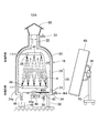
- the first embodiment is a desalination apparatus (solid-liquid separation apparatus) 16 composed of an evaporation apparatus (heating vaporization apparatus) 12 and a condensing apparatus 14.
- this desalination apparatus 16 can be used for operations such as distillation, solid-liquid separation, and liquid removal drying through vaporization (evaporation) treatment of other various liquids to be treated.
- the evaporation apparatus 12 basically includes an evaporation tower (apparatus main body) 18 having a greenhouse effect, and a liquid material injection means 20 disposed in the evaporation tower 18.
- the evaporation tower 18 is a cylindrical body having a truncated cone shape on the ceiling side.
- the evaporating tower 18 is not limited to the form shown in the figure, and may have any shape such as a rectangular tube or a rectangular box.
- the ceiling is usually tapered or hemispherical in cross section so that the evaporated materials can be smoothly collected and discharged (exhaust).
- the ceiling portion includes an exhaust port 22 formed in a cylindrical shape at the upper end.
- the size of the evaporation tower 18 is assumed to be, for example, a bottom plate area of about 1 to 700 m 2 and a height of about 3 to 20 m.
- the evaporation tower 18 has a barack structure that can be easily assembled and disassembled as described below, as in a normal greenhouse. By using the barrack structure, the equipment cost is reduced.
- the base plate 24 and the aggregate 26 formed on the base plate 24 form a frame 28 constituting the main body shape, and a flexible transparent plastic sheet (for example, a vinyl sheet) is formed on the frame (framework).
- the outer wall portion 30 is formed by covering or assembling a transparent plate material such as transparent inorganic / organic glass.
- a metal wire (pipe), a plastic-coated metal wire (composite wire), a plastic wire (pipe), wood, bamboo, or the like can be selected as appropriate.
- the outer wall 30 is preferably lined with a thin transparent material 31 from the standpoint of heat insulation and prevention of condensation.
- the transparent plastic sheet or organic / inorganic glass may have a double wall structure.
- a heat insulating transparent cloth such as a cold chill
- Cold chill is excellent in heat insulation and anti-condensation, and can be easily attached with clips, hooks and curtains, and can be easily replaced.
- the bottom plate 24 has a heating jacket structure (heating structure) and is supported on the gantry 32, although not necessarily.
- a heating medium introduction port 34 with an on-off valve is provided in the jacket portion 24a of the bottom plate 24 so that a heating medium (warm water or steam) can be introduced, and a drain port 36 with an on-off valve is provided on the bottom side.
- the exhaust port 22 has a double-pipe structure, and the jacket portion 24a and the exhaust port 22 are communicated with each other by forming an aggregate 26 that connects them with a pipe.
- the heat medium introduced into the jacket portion 24a of the bottom plate 24 reaches the annular space of the double tube forming the exhaust port 22 through the pipe forming the frame 28, and warms the evaporation tower 18 from the outer peripheral side.
- Reference numeral 23 denotes a steam exhaust port with an on-off valve.
- a heating pipe (auxiliary heating means) 19 is disposed in the vicinity of the inner peripheral wall of the evaporation tower 18 at a position slightly above and outside the lower injection pipe 40A.
- An electric heater or the like may be used instead of the heating tube 19.
- the size of the evaporation tower 18 and the condensation tower 50 is not particularly limited.
- Evaporation tower 18 bottom area 1-700m 2 , height 3-20m
- Condensing tower 50 Floor area: 3.5-23m 2 , height 3.5-23m Select from the range of.
- the bottom plate may be made of concrete or the ground (between soil and tatami). In that case, you may distribute a heating means (heating piping, an electric heater, etc.) in the ground or the ground surface.
- a heating means heating piping, an electric heater, etc.
- the heating means is arranged as described above, assuming that the evaporator should be operated continuously even when solar heat cannot be used (at night, cloudy, rainy weather, etc.).
- jet pipes 40 and 40A each having a number of jet nozzles 38 oppose each other so that liquids to be treated (including suspensions) jetted from the jet nozzles 38 can collide with each other. Arranged and configured.
- the collision position is usually near the center of the inside of the greenhouse evaporator tower.
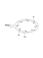
- a pair of upper and lower injection pipes 40, 40A each having a large number of injection nozzles 38 are arranged vertically, and the injection directions of the injection nozzles 38 of the upper and lower injection pipes 40, 40A are intermediate. It is in an oblique direction (slightly inside) so that it can collide with the position. As a result, the collision position of the liquid to be treated is located inside the lower injection pipe 40A. That is, when salt is recovered from seawater, the occurrence of clogging of the injection nozzle can be reduced as much as possible.
- the tip nozzle inclination angle (nozzle injection) ⁇ varies depending on the viscosity, concentration, etc. of the liquid to be treated (evaporation target), and is usually selected appropriately within a range of 5 to 45 °.
- the angle is 10 to 30 °, preferably 15 to 25 °.
- injection pipes 40 and 40A are ring-shaped, but a plurality of injection pipes may be arranged in parallel, or a grid-shaped communication pipe may be used.
- the opposing form of the injection tube was up and down, the opposing form can be left and right or front and rear, or an injection nozzle can be formed inside the ring injection pipe to cause collision in the lateral direction.
- the evaporation apparatus 12 is an apparatus for evaporating a liquid component from the liquid to be processed and recovering a solute (salt).
- the scraping rake 42 is arranged immediately above the bottom plate 24.
- the scraping rake 42 is connected to a drive shaft 44 a of a reduction motor 44.
- a product take-out port 46 with an on-off valve is formed at the scraping portion of the scraping rake (inclined plate) 42 of the bottom plate 24.
- a collection box 48 is disposed below the product outlet 46.
- the rotational speed of the scraping rake 42 varies depending on the type of evaporation residue and the deposition mode. Usually, select appropriately within the range of 0.5-3min- 1 .
- the condensing device 14 is connected to the exhaust port 22 of the evaporation tower 18 and the steam inlet 49 formed in the upper part of the condensing tower 50 via a connecting pipe 51.
- the vapor from the evaporator 12 can be introduced into the condensing tower 50.
- a condensate storage part (tub) 54 having a heat exchange pipe 52 disposed on the bottom side is provided in a condensing tower (apparatus body) 50 of the condensing device 14, and a contact filler 56 is disposed above the condensate storage part 54.
- a sprinkling pipe 58 is disposed above the steam inlet 49 of the condensing tower 50.
- the inlet of the sprinkling pipe 58 is connected via a circulation pipe 62 provided with a circulation pump 60 so that the condensate from the condensate reservoir 54 can be circulated.
- An overflow pipe 55 for collecting fresh water is provided at an intermediate height position of the condensate storage unit 54.
- the overflow pipe 55 is connected to a water storage tank or an irrigation pump by a hose or the like.
- Condensation tower 50 is also easy to assemble and disassemble by forming a skeleton with the bathtub and aggregate forming condensate reservoir 54 and forming outer wall 30 with aluminum foil, a reflector or the like, similarly to evaporation tower 18. A barack structure can be obtained.
- the cooling heat medium can pass through the heat exchange pipe 52.
- the cooling heat medium may be seawater (liquid to be treated), and may further be a cooling heat medium cooled by a cooling tower or a chiller.
- the contact filler (filler) 56 is not particularly limited and may be a Raschig ring or the like used as a normal filler, but has the following configuration described in Japanese Patent No. 193139 (a filler element is desirable. The contact efficiency is better than that of the filler.
- a plate-like packing element in which a number of flat resin pipes made of synthetic resin cut in accordance with the height of the counter-flow contact portion of the cooling tower are connected in parallel at least at the upper end so as to be independently swingable.” If the injection pressure of the circulating water injected from the water spray pipe is set to a predetermined pressure (for example, 0.1 MPa or more), the introduction of steam from the evaporator is promoted by the ejector effect (suction effect).
- a predetermined pressure for example, 0.1 MPa or more
- the liquid to be treated can be supplied to the evaporator 12 via the solar water heater 64.
- the installation location of the solar water heater 64 is the ceiling part of the condensing tower 50 in this embodiment.
- the solar water heater 64 is not particularly limited in its installation position as long as the supply pipes to be processed can be disposed between the outlet 64b and the injection pipes 40, 40A of the evaporation tower 18 and the inlets 40a, 40a.
- the heat exchange pipe 52 may be interposed between the inlet 64a of the solar water heater 64 and the intake of the treated water (raw material).
- the condensation tower (condenser main body) 50 is arranged on the north side or the west side of the evaporation tower (evaporator main body) 18, and a reflection treatment film is formed on the outer peripheral surface of the condensation tower 50 or covered with a reflection film. It is desirable to keep it.
- the solar heat utilization factor of the evaporator 12 can be increased.
- reflection treatment film As the reflection treatment film, mirror plating or the like can be used, and as the reflection film, silver vinyl, aluminum vapor-deposited heat insulating / insulating sheet, or the like can be used. Similarly, a heat shield / heat insulating sheet may be provided on the inner peripheral surface of the outer wall 30 of the condensation tower, or a reflection process may be performed.
- the structural material (aggregate) and wall material of the condensation tower body can be formed of the same materials as those in the evaporation tower 18.
- seawater desalination treatment is performed in the autumn using an evaporation tower 18 having an inner diameter of 2 m and an inner height of 6 m and a condensing tower 50 having an inner diameter of 60 cm and an inner height of 6.5 m. went.
- the lower injection pipe and the upper injection pipe used the following specifications.
- Lower injection pipe ring center diameter: 180 cm, pipe inner diameter: 4 cm, injection nozzle (nozzle diameter 0.4 mm, nozzle inclination angle ⁇ : 10 °): 70
- Upper injection pipe ring center diameter: 80 cm, pipe inner diameter: 4 cm, injection nozzle (nozzle diameter 0.4 mm): 30,
- Environmental conditions are: Weather: Sunny, Temperature: 25 ° C, Evaporating tower temperature: 31 ° C, Humidity (RH) 48%, Seawater is taken up with a water pump (not shown) (0.15 MPa)
- Injection amount Injection was performed under the condition of 600 dm 3 h ⁇ 1 .
- the intake pump used was a magnet type with a diameter of 20 A, a lift of 18 m, and a discharge amount of 20 dm 3 min ⁇ 1 .
- the circulation pump 60 was of a line type and had a diameter of 32 A, a lift of 8 m, and a discharge amount of 150 dm 3 min ⁇ 1 .
- the injection nozzle 38 of the injection pipe 40 ⁇ / b> A may be a curved nozzle that can generate a vortex injection flow inside the upper position of the injection pipe.
- the tip inclination angle ⁇ is set to 5 to 45 °, and usually a twisted vortex that is counterclockwise (left-turning) in the northern hemisphere and clockwise (right-turning) in the southern hemisphere is generated. Attach the nozzle to the ring-shaped injection tube. This is to use the Coriolis force of the earth's rotation.
- sea salt including hydrated material
- the second embodiment is the same as the first embodiment shown in FIG. 1 except that the condensing device 14 is discarded, and only the evaporation device 12A is used. (Dry product), slurry component, or high boiling point component is recovered.
- the ceiling part of the evaporation tower 18 is formed in a dome shape, and a Jinkasa cap 66 is attached to the open upper end part of the exhaust port 22 so that rainwater or the like does not enter.
- the cap shape is not limited to the Jinkasa shape, and may be a reverse bowl shape. Furthermore, if the tip of the cylindrical body that forms the exhaust port 22 is slightly directed in the perpendicular direction or downward, a cap for preventing intrusion of rainwater or the like is unnecessary.
- one (or plural) reflecting mirrors 68 corresponding to the size of the evaporation apparatus (evaporation tower) is installed.
- the reflecting mirror 68 is supported by a support rod 70 with a carriage via an angle adjusting jig 69.
- the mirror surface of the reflecting mirror 68 is arbitrary, such as a glass mirror, a resin plating plate, a steel plating plate.
- the number of injection tubes is not limited to one or one, and a plurality of pairs or a plurality of injection tubes may be provided.
- the evaporation apparatus of the present invention can also process (solid-liquid separation) muddy water, surplus sludge water from a wastewater treatment facility, and suspension (including slurry) such as paint.
- the liquids to be treated can be separated from each other through a flocculation operation using a flocculant without dehydrating with a dehydrator.
- the spray nozzle diameter is such that the solid dispersed particles in the slurry can pass, the solid dispersed particles and the liquid are simultaneously sprayed into the evaporation tower, so that the solid dispersed particles fall to the floor surface. As it accumulates, the liquid evaporates.
- the liquid is agglomerated by a condensing device, it can be recovered as distilled water when the liquid to be treated is aqueous, or as a regenerated solvent when the liquid to be treated is solvent-based.
Landscapes
- Chemical & Material Sciences (AREA)
- Chemical Kinetics & Catalysis (AREA)
- Engineering & Computer Science (AREA)
- Life Sciences & Earth Sciences (AREA)
- Physics & Mathematics (AREA)
- Toxicology (AREA)
- Health & Medical Sciences (AREA)
- Sustainable Energy (AREA)
- Sustainable Development (AREA)
- Thermal Sciences (AREA)
- Hydrology & Water Resources (AREA)
- Environmental & Geological Engineering (AREA)
- Water Supply & Treatment (AREA)
- Organic Chemistry (AREA)
- Heat Treatment Of Water, Waste Water Or Sewage (AREA)
- Treatment Of Sludge (AREA)
- Vaporization, Distillation, Condensation, Sublimation, And Cold Traps (AREA)
Abstract
L'invention concerne un appareil d'évaporation de conception inédite, capable de réaliser avec un bon rendement non seulement le dessalement d'eau salée (traitement de désalinisation) avec des coûts d'installation / d'exploitation réduits, mais également la gazéification / la séparation de divers liquides (en particulier une évaporation ou séparation solide-liquide). L'appareil d'évaporation (12) comporte une tour d'évaporation (18) à structure en hangar créant un effet de serre, et des moyens d'injection du liquide à traiter disposés dans la tour d'évaporation (18). Les moyens d'injection comprennent des canalisations d'injection supérieures et inférieures (40, 40A) munies d'une multiplicité de buses d'injection (38) et disposées de façon à se faire face de telle sorte que les liquides à traiter injectés à partir des buses d'injection (38) individuelles puissent se heurter. L'appareil d'évaporation (12) est utilisé comme appareil de dessalement (16) ou similaire en combinaison avec un appareil de condensation (14).
Applications Claiming Priority (2)
| Application Number | Priority Date | Filing Date | Title |
|---|---|---|---|
| JP2008-016945 | 2008-01-28 | ||
| JP2008016945A JP5578767B2 (ja) | 2008-01-28 | 2008-01-28 | 蒸発装置 |
Publications (1)
| Publication Number | Publication Date |
|---|---|
| WO2009096370A1 true WO2009096370A1 (fr) | 2009-08-06 |
Family
ID=40912723
Family Applications (1)
| Application Number | Title | Priority Date | Filing Date |
|---|---|---|---|
| PCT/JP2009/051231 Ceased WO2009096370A1 (fr) | 2008-01-28 | 2009-01-27 | Appareil d'évaporation |
Country Status (2)
| Country | Link |
|---|---|
| JP (1) | JP5578767B2 (fr) |
| WO (1) | WO2009096370A1 (fr) |
Cited By (10)
| Publication number | Priority date | Publication date | Assignee | Title |
|---|---|---|---|---|
| WO2015084494A3 (fr) * | 2013-12-06 | 2016-01-21 | Exxonmobil Upstream Research Company | Procédé et dispositif de séparation d'hydrocarbures et de contaminants au moyen d'un ensemble de pulvérisation |
| CN106488599A (zh) * | 2016-11-03 | 2017-03-08 | 舟山梅朋水处理有限公司 | 一种用于流体的加热器、过流加热系统和盐雾加热蒸发系统 |
| CN107143835A (zh) * | 2017-06-29 | 2017-09-08 | 濮阳市华凌石油机械化工有限公司 | 压裂液返排液蒸发器 |
| US9951356B2 (en) | 2013-12-12 | 2018-04-24 | Dow Global Technologies Llc | Processes to prepare elongated 2-ketoacids and C6-C10 compounds therefrom via genetic modifications to microbial metabolic pathways |
| US10260060B2 (en) | 2014-12-10 | 2019-04-16 | Dow Global Technologies Llc | Genetically modified phenylpyruvate decarboxylase, processes to prepare, and uses thereof |
| CN110563234A (zh) * | 2019-09-02 | 2019-12-13 | 龚建国 | 一种低耗能海水淡化系统及方法 |
| US10995322B2 (en) | 2016-09-30 | 2021-05-04 | Dow Global Technologies Llc | Processes to prepare elongated 2-ketoacids and C5-C10 compounds therefrom via genetic modifications to microbial metabolic pathways |
| US11230705B2 (en) | 2017-09-29 | 2022-01-25 | Dow Global Technologies Llc | Genetically modified isopropylmalate isomerase enzyme complexes and processes to prepare elongated 2-ketoacids and C5-C10 compounds therewith |
| EP4134611A4 (fr) * | 2020-04-08 | 2023-09-06 | Wga Water Global Access, S.L. | Dispositif de dessalement par compression de jet d'eau liquide |
| JP2025127259A (ja) * | 2024-02-20 | 2025-09-01 | 豐裕 劉 | 廃液を加速回収し浄化する蒸留機の構造 |
Families Citing this family (4)
| Publication number | Priority date | Publication date | Assignee | Title |
|---|---|---|---|---|
| CN102358629A (zh) * | 2011-09-24 | 2012-02-22 | 无锡市兴麟染整环保有限公司 | 海水淡化用雾化塔 |
| KR101581707B1 (ko) * | 2015-06-03 | 2015-12-31 | (주)효성엔바이로 | 원형 침전지의 슬러지 수집기 |
| CN105819531B (zh) * | 2016-05-12 | 2019-05-10 | 上海朴是环境科技股份有限公司 | 一种节能热泵型中温喷雾蒸发系统 |
| CN106765704B (zh) * | 2016-12-26 | 2019-07-09 | 南京航空航天大学 | 双热质耦合太阳能热空气型蒸发系统及其方法 |
Citations (5)
| Publication number | Priority date | Publication date | Assignee | Title |
|---|---|---|---|---|
| JPH1071320A (ja) * | 1996-08-30 | 1998-03-17 | Koichi Nakamura | 水資源造出装置 |
| JPH1192134A (ja) * | 1997-09-18 | 1999-04-06 | Hideo Taira | 海塩製造装置および方法 |
| JPH11290725A (ja) * | 1998-04-07 | 1999-10-26 | Japan Metals & Chem Co Ltd | スプレードライヤ用噴霧ノズル装置 |
| JP2001157555A (ja) * | 1999-09-20 | 2001-06-12 | Umai Kk | ニガリ含有食塩粒とその製造方法 |
| JP2006150147A (ja) * | 2002-12-19 | 2006-06-15 | Ebara Corp | 塩類等含有水の淡水化装置 |
Family Cites Families (6)
| Publication number | Priority date | Publication date | Assignee | Title |
|---|---|---|---|---|
| JPS4026297Y1 (fr) * | 1965-03-20 | 1965-09-07 | ||
| JPS425091Y1 (fr) * | 1966-05-26 | 1967-03-15 | ||
| JPS5388558U (fr) * | 1976-12-22 | 1978-07-20 | ||
| JPH0780240A (ja) * | 1993-06-21 | 1995-03-28 | Nippon Refine Kk | 有機溶剤の回収方法及び装置 |
| DE19631520C2 (de) * | 1996-08-03 | 2001-10-18 | Kavernen Bau Und Betr S Gmbh | Verfahren und Anlage zur soltechnischen Gewinnung von Evaporiten und Aufbereitung von Salzlösungen |
| EP1951624A4 (fr) * | 2005-11-22 | 2012-01-18 | Australian Creative Technologies Pty Ltd | Systeme de conduits |
-
2008
- 2008-01-28 JP JP2008016945A patent/JP5578767B2/ja active Active
-
2009
- 2009-01-27 WO PCT/JP2009/051231 patent/WO2009096370A1/fr not_active Ceased
Patent Citations (5)
| Publication number | Priority date | Publication date | Assignee | Title |
|---|---|---|---|---|
| JPH1071320A (ja) * | 1996-08-30 | 1998-03-17 | Koichi Nakamura | 水資源造出装置 |
| JPH1192134A (ja) * | 1997-09-18 | 1999-04-06 | Hideo Taira | 海塩製造装置および方法 |
| JPH11290725A (ja) * | 1998-04-07 | 1999-10-26 | Japan Metals & Chem Co Ltd | スプレードライヤ用噴霧ノズル装置 |
| JP2001157555A (ja) * | 1999-09-20 | 2001-06-12 | Umai Kk | ニガリ含有食塩粒とその製造方法 |
| JP2006150147A (ja) * | 2002-12-19 | 2006-06-15 | Ebara Corp | 塩類等含有水の淡水化装置 |
Cited By (16)
| Publication number | Priority date | Publication date | Assignee | Title |
|---|---|---|---|---|
| WO2015084494A3 (fr) * | 2013-12-06 | 2016-01-21 | Exxonmobil Upstream Research Company | Procédé et dispositif de séparation d'hydrocarbures et de contaminants au moyen d'un ensemble de pulvérisation |
| EA032756B1 (ru) * | 2013-12-06 | 2019-07-31 | Эксонмобил Апстрим Рисерч Компани | Способ и устройство для разделения углеводородов и загрязняющих веществ посредством распылительного узла |
| US9869511B2 (en) | 2013-12-06 | 2018-01-16 | Exxonmobil Upstream Research Company | Method and device for separating hydrocarbons and contaminants with a spray assembly |
| US9951356B2 (en) | 2013-12-12 | 2018-04-24 | Dow Global Technologies Llc | Processes to prepare elongated 2-ketoacids and C6-C10 compounds therefrom via genetic modifications to microbial metabolic pathways |
| US10260060B2 (en) | 2014-12-10 | 2019-04-16 | Dow Global Technologies Llc | Genetically modified phenylpyruvate decarboxylase, processes to prepare, and uses thereof |
| US10995322B2 (en) | 2016-09-30 | 2021-05-04 | Dow Global Technologies Llc | Processes to prepare elongated 2-ketoacids and C5-C10 compounds therefrom via genetic modifications to microbial metabolic pathways |
| US11236310B2 (en) | 2016-09-30 | 2022-02-01 | Dow Global Technologies Llc | Process to prepare elongated 2-ketoacids and C-5-C10 compounds therefrom via genetic modifications to microbial metabolic pathways |
| CN106488599A (zh) * | 2016-11-03 | 2017-03-08 | 舟山梅朋水处理有限公司 | 一种用于流体的加热器、过流加热系统和盐雾加热蒸发系统 |
| CN107143835A (zh) * | 2017-06-29 | 2017-09-08 | 濮阳市华凌石油机械化工有限公司 | 压裂液返排液蒸发器 |
| US11230705B2 (en) | 2017-09-29 | 2022-01-25 | Dow Global Technologies Llc | Genetically modified isopropylmalate isomerase enzyme complexes and processes to prepare elongated 2-ketoacids and C5-C10 compounds therewith |
| US11898181B2 (en) | 2017-09-29 | 2024-02-13 | Dow Global Technologies Llc | Genetically modified isopropylmalate isomerase enzyme complexes and processes to prepare elongated 2-ketoacids and C5-C10 compounds therewith |
| CN110563234A (zh) * | 2019-09-02 | 2019-12-13 | 龚建国 | 一种低耗能海水淡化系统及方法 |
| CN110563234B (zh) * | 2019-09-02 | 2021-12-03 | 衡阳远通物流有限公司 | 一种低耗能海水淡化系统及方法 |
| EP4134611A4 (fr) * | 2020-04-08 | 2023-09-06 | Wga Water Global Access, S.L. | Dispositif de dessalement par compression de jet d'eau liquide |
| JP2025127259A (ja) * | 2024-02-20 | 2025-09-01 | 豐裕 劉 | 廃液を加速回収し浄化する蒸留機の構造 |
| JP7769413B2 (ja) | 2024-02-20 | 2025-11-13 | 豐裕 劉 | 廃液を加速回収し浄化する蒸留機の構造 |
Also Published As
| Publication number | Publication date |
|---|---|
| JP5578767B2 (ja) | 2014-08-27 |
| JP2009172562A (ja) | 2009-08-06 |
Similar Documents
| Publication | Publication Date | Title |
|---|---|---|
| JP5578767B2 (ja) | 蒸発装置 | |
| Fath | Solar distillation: a promising alternative for water provision with free energy, simple technology and a clean environment | |
| US4363703A (en) | Thermal gradient humidification-dehumidification desalination system | |
| US10183872B2 (en) | Counter circulating liquid processing system by repeatedly re-using thermal energy | |
| EP2804682B1 (fr) | Station de dessalement utilisant une pompe à chaleur et de l'énergie photovoltaïque | |
| US10144655B2 (en) | Systems and methods for distillation of water from seawater, brackish water, waste waters, and effluent waters | |
| CN104973638A (zh) | 一种高盐高浓度有机废液处理工艺 | |
| CN104671310B (zh) | 一种多效耦合的雾化蒸发器 | |
| Wijewardane et al. | Inventions, innovations, and new technologies: Solar Desalination | |
| US10414670B2 (en) | Systems and methods for distillation of water from seawater, brackish water, waste waters, and effluent waters | |
| AU2008336266A1 (en) | Solar distillation device | |
| WO2009047380A1 (fr) | Système évaporateur d'eaux résiduelles et analogues au moyen d'énergies renouvelables | |
| US11772988B1 (en) | Solar dome desalination system with enhanced evaporation | |
| CN205773477U (zh) | 一种太阳能制水装置 | |
| AU2008238608B2 (en) | Apparatus for purifying contaminated liquid | |
| US20140124356A1 (en) | Process for solar thermal energy production | |
| CN103359800A (zh) | 一种斯特林热泵海水淡化装置 | |
| Ullah et al. | An overview of solar thermal desalination technologies | |
| CN204981215U (zh) | 太阳能薄膜废水蒸发浓缩装置 | |
| AU2010100471A4 (en) | Solar Distillation Device | |
| RU2553880C2 (ru) | Устройство и способ для опреснения морской воды | |
| CN101648734A (zh) | 太阳能海水淡化器 | |
| CN119929949B (zh) | 一种苦咸湖水净化装置 | |
| US12324993B1 (en) | Direct solar desalination with atomized droplets and heat recovery | |
| JP2000325941A5 (fr) |
Legal Events
| Date | Code | Title | Description |
|---|---|---|---|
| 121 | Ep: the epo has been informed by wipo that ep was designated in this application |
Ref document number: 09705584 Country of ref document: EP Kind code of ref document: A1 |
|
| NENP | Non-entry into the national phase |
Ref country code: DE |
|
| 122 | Ep: pct application non-entry in european phase |
Ref document number: 09705584 Country of ref document: EP Kind code of ref document: A1 |