WO2009096556A1 - Endoscope de traitement - Google Patents
Endoscope de traitement Download PDFInfo
- Publication number
- WO2009096556A1 WO2009096556A1 PCT/JP2009/051645 JP2009051645W WO2009096556A1 WO 2009096556 A1 WO2009096556 A1 WO 2009096556A1 JP 2009051645 W JP2009051645 W JP 2009051645W WO 2009096556 A1 WO2009096556 A1 WO 2009096556A1
- Authority
- WO
- WIPO (PCT)
- Prior art keywords
- treatment
- coil
- bending
- mounting
- wire
- Prior art date
- Legal status (The legal status is an assumption and is not a legal conclusion. Google has not performed a legal analysis and makes no representation as to the accuracy of the status listed.)
- Ceased
Links
Images



















Classifications
-
- A—HUMAN NECESSITIES
- A61—MEDICAL OR VETERINARY SCIENCE; HYGIENE
- A61B—DIAGNOSIS; SURGERY; IDENTIFICATION
- A61B34/00—Computer-aided surgery; Manipulators or robots specially adapted for use in surgery
- A61B34/30—Surgical robots
-
- A—HUMAN NECESSITIES
- A61—MEDICAL OR VETERINARY SCIENCE; HYGIENE
- A61B—DIAGNOSIS; SURGERY; IDENTIFICATION
- A61B1/00—Instruments for performing medical examinations of the interior of cavities or tubes of the body by visual or photographical inspection, e.g. endoscopes; Illuminating arrangements therefor
- A61B1/00131—Accessories for endoscopes
- A61B1/00133—Drive units for endoscopic tools inserted through or with the endoscope
-
- A—HUMAN NECESSITIES
- A61—MEDICAL OR VETERINARY SCIENCE; HYGIENE
- A61B—DIAGNOSIS; SURGERY; IDENTIFICATION
- A61B34/00—Computer-aided surgery; Manipulators or robots specially adapted for use in surgery
- A61B34/30—Surgical robots
- A61B34/37—Leader-follower robots
-
- A—HUMAN NECESSITIES
- A61—MEDICAL OR VETERINARY SCIENCE; HYGIENE
- A61B—DIAGNOSIS; SURGERY; IDENTIFICATION
- A61B17/00—Surgical instruments, devices or methods
- A61B17/00234—Surgical instruments, devices or methods for minimally invasive surgery
-
- A—HUMAN NECESSITIES
- A61—MEDICAL OR VETERINARY SCIENCE; HYGIENE
- A61B—DIAGNOSIS; SURGERY; IDENTIFICATION
- A61B17/00—Surgical instruments, devices or methods
- A61B17/28—Surgical forceps
- A61B17/29—Forceps for use in minimally invasive surgery
-
- A—HUMAN NECESSITIES
- A61—MEDICAL OR VETERINARY SCIENCE; HYGIENE
- A61B—DIAGNOSIS; SURGERY; IDENTIFICATION
- A61B18/00—Surgical instruments, devices or methods for transferring non-mechanical forms of energy to or from the body
- A61B18/04—Surgical instruments, devices or methods for transferring non-mechanical forms of energy to or from the body by heating
- A61B18/12—Surgical instruments, devices or methods for transferring non-mechanical forms of energy to or from the body by heating by passing a current through the tissue to be heated, e.g. high-frequency current
- A61B18/14—Probes or electrodes therefor
- A61B18/1492—Probes or electrodes therefor having a flexible, catheter-like structure, e.g. for heart ablation
-
- A—HUMAN NECESSITIES
- A61—MEDICAL OR VETERINARY SCIENCE; HYGIENE
- A61B—DIAGNOSIS; SURGERY; IDENTIFICATION
- A61B17/00—Surgical instruments, devices or methods
- A61B17/28—Surgical forceps
- A61B17/29—Forceps for use in minimally invasive surgery
- A61B2017/2901—Details of shaft
- A61B2017/2905—Details of shaft flexible
-
- A—HUMAN NECESSITIES
- A61—MEDICAL OR VETERINARY SCIENCE; HYGIENE
- A61B—DIAGNOSIS; SURGERY; IDENTIFICATION
- A61B17/00—Surgical instruments, devices or methods
- A61B17/28—Surgical forceps
- A61B17/29—Forceps for use in minimally invasive surgery
- A61B2017/2901—Details of shaft
- A61B2017/2906—Multiple forceps
-
- A—HUMAN NECESSITIES
- A61—MEDICAL OR VETERINARY SCIENCE; HYGIENE
- A61B—DIAGNOSIS; SURGERY; IDENTIFICATION
- A61B17/00—Surgical instruments, devices or methods
- A61B17/28—Surgical forceps
- A61B17/29—Forceps for use in minimally invasive surgery
- A61B2017/2926—Details of heads or jaws
- A61B2017/2927—Details of heads or jaws the angular position of the head being adjustable with respect to the shaft
-
- A—HUMAN NECESSITIES
- A61—MEDICAL OR VETERINARY SCIENCE; HYGIENE
- A61B—DIAGNOSIS; SURGERY; IDENTIFICATION
- A61B34/00—Computer-aided surgery; Manipulators or robots specially adapted for use in surgery
- A61B34/30—Surgical robots
- A61B2034/301—Surgical robots for introducing or steering flexible instruments inserted into the body, e.g. catheters or endoscopes
Definitions
- the present invention relates to a treatment endoscope. This application is filed in US application No. 1 filed Feb. 1, 2008. Claims priority based on 12 / 024,704, the contents of which are incorporated herein.
- an arm portion whose tip can be bent is inserted into a plurality of lumens arranged in a soft insertion portion inserted from a patient's mouth.
- each treatment tool can be approached from different directions, and multiple procedures can be continued with one endoscope inserted into the body. Can be done.
- the above-described treatment endoscope tends to be large in size, particularly when the operation part for operating the arm part tends to be large, in order to enable complicated operation of the arm part in order to enable various procedures. And the structure tends to be complicated. Since the procedure performed using the treatment endoscope requires high cleanliness as in the case of surgery, the treatment endoscope needs to be sterilized. In the case of becoming complicated and complicated, there is a problem that sterilization work is difficult.
- the present invention has been made in view of the above, and an object of the present invention is to provide a treatment endoscope capable of performing a sterilization operation easily and ensuring high cleanliness.
- a flexible sheath capable of bending operation, observation means for observing the distal end side of the sheath, and an arm protruding from the distal end of the sheath and capable of bending operation.
- the treatment endoscope is detachably connected to the operation unit.
- the arm part and the endoscope part can be operated in a more sanitary state by making it a sterilized disposable unit or by sterilizing and reusing it. it can.
- FIG. 3 is an AA arrow view of FIG. 2 along the axial direction of the first operation unit. It is AB arrow line view of FIG.
- FIG. 5 is a cross-sectional view taken along the line AC-AC in FIG. 4.
- FIG. 5 is a sectional view taken along the line AD-AD in FIG. 4.
- FIG. 9 is a sectional view taken along line AE-AE in FIG. 8.
- FIG. 11 is a cross-sectional view taken along the line AF-AF in FIG. 10 before a treatment instrument is inserted. It is a perspective view of a piston. It is sectional drawing which expands and shows the 1st operation stick of FIG. It is a figure which expands and shows a channel. It is a top view which shows a treatment tool.
- FIG. 16 is a cross-sectional view taken along AG-AG in FIG. 15. It is a figure explaining a mode that a protection member is attached to a ring. It is the figure which attached the protection member to the ring. It is a perspective view of a cam.
- FIG. 20 is an AH arrow view of FIG. 19.
- FIG. 16 is a cross-sectional view taken along the line AI-AI in FIG. 15.
- FIG. 16 is a cross-sectional view taken along line AJ-AJ in FIG.
- It is a schematic diagram explaining operation
- FIG. 30 It is a figure explaining the operation which pushes up a piston with a cam, when extracting a treatment implement. It is the figure which pushed up a piston by rotating a cam. It is a figure which shows the operation part which has arrange
- FIG. 1 shows the structure of the endoscope for treatment of 1st Embodiment of this invention. It is a figure which shows the operation part of the endoscope for the treatment. It is a perspective view which shows a 1st wire unit. It is a figure which decomposes
- the treatment endoscope according to the present invention includes an operation unit that extracts a portion necessary for treatment, that is, an operation unit that operates the arm unit and a treatment tool, and an endoscope operation unit that operates the endoscope.
- the function is divided, and the operation unit can be operated at a position away from the endoscope.
- the operation unit is built in the endoscope operation unit, the operator has to perform all the operations, which makes the operation complicated.
- two operators are It becomes possible to share roles between mirror operation and treatment operation, and the operation becomes easy.
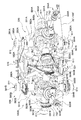
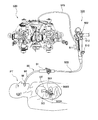
- FIG. 1 is a diagram showing an example of a basic structure of a treatment endoscope according to the present invention.
- an endoscope insertion portion 503 is integrally extended from one end of an endoscope operation portion 502.
- the endoscope insertion portion 503 is long and flexible, and its configuration is described in US Application No. 11 / 435,183 and NO. 11 / 652,880. That is, the endoscope insertion portion 503 has a sheath 301, and first and second arm portions 302A and 302B are provided at the distal end thereof.
- the treatment portions 505A and 505B of the treatment tools 504A and 504B protrude from the distal ends of the arm portions 302A and 302B, respectively.
- a first bending portion 306 and a second bending portion 308 are formed in order from the distal end side on each of the arm portions 302A and 302B, and cooperate with the third bending portion 203B formed in the first sheath 301. Therefore, bending operation is possible in the body.
- the first and second arm portions 302A and 302B are the same as those in US Application No. 11 / 652,880 may be inserted into another sheath that protrudes from the distal end of the sheath 301. In FIG. 1, the operation unit 520 is enlarged and illustrated for easy understanding.
- the endoscope operation unit 502 is provided with a forceps plug 510 on a side surface on one end side that is continuous with the endoscope insertion unit 503.
- the forceps plug 510 communicates with a working channel formed in the first sheath 301. If another treatment tool (not shown) is inserted from here, another treatment from the distal end of the endoscope insertion portion 503 is performed. The tool can be projected.
- the endoscope operation unit 502 is provided with a switch 511, an angle knob 512, and a universal cable 513 connected to a control device (not shown).
- the switch 511 is operated, for example, when air is supplied, water is supplied, or suction is performed through a channel formed in the first sheath 301.
- the angle knob 512 is used when the third bending portion 203B is bent in four directions with respect to the axis.
- connection sheath 515 is extended from the other end of the endoscope operation unit 502, and an operation unit 520 is provided at the end of the connection sheath 515.
- the operation unit 520 has a base 521 for fixing the connection sheath 515, and the first operation unit 530A and the second operation unit 530B are attached to the base 521.
- the first operation unit 530A has an operation stick 531A into which the operation unit 506A of the treatment instrument 504A passed through the first arm unit 302A is inserted, and the operation unit 506A can advance and retreat in the axial direction via the operation stick 531A. And tiltably supported in four directions with the axis as the center.
- the second operation unit 530B has an operation stick 531B into which the operation unit 506B of the treatment instrument 504B passed through the second arm unit 302B is inserted, and the operation unit 506B can advance and retreat in the axial direction via the operation stick 531B. And tiltably supported in four directions around the axis. Since the operation unit 520 is used by being fixed to a surgical bed or the like, the first and second operation units 530A and 530B can be operated.
- these operation units 530A and 530B are arranged so as to be inclined so that the connecting sheath 515 side is close to each other, and two operation units 506A and 506B (or two operation sticks 531A, 531B) is arranged open in the range of 20 ° to 100 °.
- the operation units 506A and 506B are arranged at an angle so as to open toward the operator, the operator can operate in an easy posture, and operability is improved.
- the width of the operation portion 520 on the connection sheath 515 side can be reduced.
- the arrangement (left and right direction) of the two operation units 530A and 530B can be matched.
- the operator's senses and the actual actions in the body can be easily associated with each other, and the procedure is facilitated.
- the operator since the operator operates only the operation sticks 531A and 531B and the operation units 506A and 506B of the treatment instruments 504A and 504B, the amount of force required for the operation can be reduced.
- the configuration of the first operation unit 530A will be described.
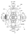
- the first operation unit 530 ⁇ / b> A has a bracket 551 ⁇ / b> A fixed to the base 521.
- the bracket 551A is fixed so that the opening 552A is substantially orthogonal to the center line of the first operation unit 530A.
- a first rotation mechanism 561A is attached to the side surface of the bracket 551A in the left-right direction.
- the first rotation mechanism 561A has a pair of support pieces 562A and 563A fixed so as to sandwich the opening 552A of the bracket 551A, and each of the support pieces 562A and 563A has one rotation shaft 564A and 565A. Has been placed.
- the rotation shafts 564A and 565A are arranged coaxially, and the frame 567A is rotatably supported with respect to the bracket 551 by the pair of rotation shafts 564A and 565A.
- the frame 567A has a quadrangular shape, and the opening is arranged in a direction orthogonal to the center line of the first operation unit 530A.
- An operation stick 531A is inserted into the frame 567A.
- the operation stick 531A is engaged with the frame 567A in the rotation direction of the rotation shafts 564A and 565A, and is inserted so as to be independently tiltable in the axial direction of the rotation shafts 564A and 565A.
- the tip 571A of the operation stick 531A extends beyond the frame 567A.
- a ball roller 572A is provided at the tip 571A.
- the ball rollers 572A are provided one by one across the center line of the operation stick 531A.
- the line connecting the centers of the two ball rollers 572A and the axes of the rotation shafts 564A and 565A of the first rotation mechanism 561A are In the state shown (the operation stick 531A is not tilted), they are parallel.
- the distance Laa from the rotation shafts 564A, 565A to the ball roller 572A is, for example, 50 to 200 mm.
- a frame 580A of the second rotation mechanism 581A is disposed so as to sandwich the ball roller 572A and to be in sliding contact with the ball roller 572A.
- the frame 580A is rotatably supported by a pair of rotating shafts 584A and 585A.
- the pair of rotation shafts 584A and 585A are arranged on the same axis, and the axis thereof is orthogonal to the pair of rotation shafts 564A and 555A of the first rotation mechanism 561A and also orthogonal to the center line of the first operation unit 530A. Are arranged to be.
- the rotation shafts 584A and 585A are rotatably supported by support pieces 582A and 583A that are fixed to the side surfaces in the vertical direction of the bracket 551A one by one.
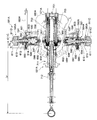
- the configuration of the rotation shafts 584A and 585A of the second rotation mechanism 581A will be described. Since the rotation shafts 584A and 585A have the same configuration, the rotation shaft 584A will be described as an example.
- the rotation shaft 584A has a bearing 591 fixed to the support piece 582A.
- the bearing 591 has a flange formed at one end of a cylinder, and is fixed to the support piece 582A through a bolt in a hole drilled in the flange.
- Outer rings of two bearings 592 and 593 are press-fitted apart in the axial direction inside the cylindrical portion of the bearing 591, and the drive shaft 594 is rotatable with respect to the bearing 591 via these bearings 592 and 593. Supported.
- the drive shaft 594 has a reduced diameter portion passing through the bearing 591.
- One end of the drive shaft 594 is expanded to a diameter substantially equal to the outer diameter of the bearing 591, and a coil spring 596 is wound from the outer periphery of the drive shaft 594 to the outer periphery of the cylindrical portion of the bearing 591. Both ends 596C and 596D of the coil spring 596 are bent. One end 596 ⁇ / b> C is engaged with a groove formed in a flange 594 ⁇ / b> C formed at the end of the drive shaft 594.
- the wire shape of the coil spring 596 is a square shape. As long as it has a square shape, it may be square or rectangular.
- the end face of the drive shaft 594 on the flange 594C side is provided with a cylindrical protrusion 594D on the central axis.
- a plurality of screw holes are formed at equal intervals around the protrusion 594D. Of these screw holes, one rotation pin 597 is screwed into two screw holes that are shifted by 180 degrees in the circumferential direction.
- the inner ring of the bearing 598 is press-fitted and fixed to the protrusion 594D.
- a bearing 599 is mounted on the outer periphery of the bearing 598.
- the bearing 599 has a cylindrical portion 599D in which a flange is formed.
- a ring pressing member 600 is inserted in advance into the cylindrical portion 599D, and the ring pressing member 600 is pressed toward the drive shaft 594 by a pressurizing screw 602 through a flat spring 601.
- a plurality of through holes 599 ⁇ / b> C are formed in the flange of the bearing 599 at equal intervals in the circumferential direction. The arrangement of these through holes 599C is equal to the arrangement of the screw holes of the drive shaft 594.
- the diameter of the through hole 599 ⁇ / b> C is larger than the outer diameter of the head of the rotating pin 597 and has play.
- a cylindrical cover 603 is attached so as to cover the flange 594C of the bearing 594 and the coil spring 576.
- a cutout 603 ⁇ / b> C is formed at the base end portion of the cover 603, and the other end 596 ⁇ / b> D of the coil spring 596 is hooked thereon.
- the cylindrical portion 599D protruding from the cover 603 by the bearing 599 is fixed to the frame 580A with a pin.
- the drive shaft 594 and the bearing 591 are connected via the coil spring 596. Since the bearing 591 is fixed to the support piece 582A, the drive shaft 594 cannot rotate in the direction in which the coil spring 596 is tightened. The coil spring 596 can rotate in the loosening direction.
- the frame 580A in contact with the operation stick 531A tilts. When the frame 580A is inclined, the bearing 594 of the rotation shaft 584A and the cover 603 are rotated.
- the coil spring 596 used for such a spring clutch needs to be manufactured from a material having high hardness. However, if a material having a high specific gravity such as iron is used, the weight of the operation unit 520 is increased. For this reason, it is preferable to use a material having a high hardness and a low specific gravity, for example, duralumin (No. 2000) or super duralumin (No. 7000).
- the coil spring 596 when the coil spring 596 is loosened to release the lock, if the rotation is transmitted via the coil spring 596, an excessive force is applied to the coil spring 596. In order not to maintain such a state, the play is set so that the head of the rotation pin 597 of the drive shaft 594 contacts the peripheral wall of the through hole 599C of the bearing 594 after the lock is released. By performing rotation transmission using the rotation pin 597, the coil spring 596 is prevented from being broken.
- the spring clutch configured as described above is not limited to this embodiment, and can also be used for a rotating mechanism of a treatment instrument and a rotating mechanism of an overtube.
- the drive shaft 584 protrudes from the flange side of the bearing 591 and is rotatably supported by the hollow shaft 612 by bearings 613 and 614.
- a sprocket 595 is fixed to the hollow shaft 612.
- a wire pulley may be used as a rotating body that pushes and pulls the wire.
- the hollow shaft 612 is rotatable with respect to the bearing 591 by a bearing 592.
- the drive shaft 594 and the hollow shaft 612 protrude beyond the sprocket 595 and are inserted into the torque limiter 611.
- the torque limiter 611 has an outer 611C fixed to the hollow shaft 612 and an inner 611D to which the drive shaft 594 is fixed.
- the inner 611D and the outer 611C rotate integrally until a preset torque is applied. When the set torque is exceeded, the outer 611C slips with respect to the inner 611D and rotation is not transmitted.
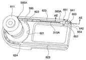
- the sprocket 595 is rotatably accommodated in a circular recess 621 formed in the support piece 583A.
- a chain 622 is wound around the teeth of the sprocket 595.
- the support piece 583A is formed with a groove 623 that is continuous with the recess 621 and into which the end of the chain 622 can be drawn.
- the groove 623 is carved deeper than the recess 621.
- the first bending wire 315A is fixed to one end of the chain 622.
- the first bending wire 315A is a wire for bending the first bending portion 306 of the first arm portion 302A in the right direction in FIG.
- the first bending wire 315 ⁇ / b> A is pulled into the adjustment tool 641 disposed at the end of the groove 623 of the support piece 583 ⁇ / b> A, passes through the coil sheath 642 connected to the adjustment tool 641, and the coil sheath 642. It is introduced into the connecting sheath 515 and routed to the first arm portion 302A.
- the adjustment tool 641 has a coil base 651 fixed to the support piece 583A.
- the coil base 651 is formed with a screw hole 651A, and an adjustment shaft 652 having a screw on the outer periphery is screwed into the screw hole 651A.
- the adjustment shaft 652 has a bottomed cylinder shape, and a coil stopper 653 is inserted from an end portion 652A corresponding to the bottom portion.
- the coil stopper 653 is prevented from coming off by engaging the flange-shaped protrusion 653A with the inner surface of the end portion 652A.
- the stopper in the opposite direction is prevented by attaching a lock screw 654 to the outer periphery.
- the end of the coil sheath 642 is fixed to the coil stopper 653.
- the first bending wire 315A is passed from the adjustment shaft 652 through the coil stopper 653 to the coil sheath 642. In the process of using the treatment endoscope 501, the first bending wire 315 ⁇ / b> A may extend and loosen.
- the coil sheath 642 advances and retreats in the axial direction together with the adjustment shaft 652.
- the first bending wire 315A is pulled with respect to the coil sheath 642, and the slackness is adjusted. Since the slack adjustment can be performed by adjusting the screw, it is not necessary to disassemble the device. Since the adjustment shaft 652 and the coil stopper 653 are rotatably engaged, the coil sheath 642 does not rotate even if the adjustment shaft 652 is rotated.
- the sprocket 595 on the rotating shaft 584A side is similarly accommodated in the support piece 582A and the chain 622 is wound around it.
- a first bending wire (not shown) is attached to the chain 622.
- the first bending wire is a wire for bending the first bending portion 306 of the first arm portion 302A leftward in FIG.
- the support piece 582A is also provided with an adjustment tool 641 so that the slack can be adjusted by moving the coil sheath 642 through which the first bending wire passes.
- the first bending wire is inserted into the coil sheath 642, is introduced into the connection sheath 515 together with the coil sheath 642, and is routed to the first arm portion 302A.
- the torque limiter 611 is provided on the rotation shafts 584A and 585A, if the force input from the operation stick 531A side is too large, the rotation of the rotation shaft 585A is transmitted to the sprocket 595. It will not be done. As a result, an excessive force is not applied to the first bending wire 315A. If the torque limiter 611 is not provided, there is a possibility that an excessive force is applied to the first bending wire 315A and breaks. However, by controlling the maximum torque with the torque limiter 611, the first bending wire 315A is controlled. Breakage is prevented.
- the torque limiter 611, the sprocket 595, and the rotation shafts 564A and 565A are arranged in this order from the outside in the axial direction, the distance between the support pieces 582A and 583A can be shortened, and the bracket 551A can be downsized. Can do. This increases the degree of freedom in layout and contributes to a reduction in size and weight.
- One rotation shaft 564A is the same as the rotation shaft 584A of the second rotation mechanism 581A except that the drive shaft 594 is attached to the frame 567A in the rotation direction via the rotation pin 597. It is configured.
- the other rotation shaft 565A is attached to the rotation shaft 585A of the second rotation mechanism 581A except that the drive shaft 594 is engaged with the frame 567A in the rotation direction via the rotation pin 597. It is the same composition as.
- a first bending upward operation wire (not shown) is connected to the sprocket 595 of one rotating shaft 564A through a chain 622.
- a first bending downward operation wire (not shown) is connected to the sprocket 595 of the other rotation shaft 565A via a chain 622.
- the first bending downward operation wire and the first bending upward operation wire are wires for bending the first bending portion 306 of the first arm portion 302A in the downward direction and the upward direction, respectively, in FIG.
- Each of the support pieces 562A and 563A is also provided with an adjustment tool 641 so that the slack can be adjusted by moving the coil sheath 642 through which the first bending downward operation wire or the first bending upward operation wire passes.
- the operation stick 531 ⁇ / b> A is fixed so that three cylindrical shafts 701, 702, and 703 are bundled at the tip portion to which the ball roller 572 ⁇ / b> A is attached.
- the central shaft 701 is longer than the other two shafts 702 and 703, and the other two shafts 702 and 703 contact the frame 567 ⁇ / b> A of the first rotation mechanism 561 ⁇ / b> A up to the abutting portion 710 serving as a rotation fulcrum.
- the central shaft 701 extends beyond the abutting portion 710.
- a second bending slider 711 is attached to the central shaft 701 so as to freely advance and retract in the axial direction. Further, a ratchet base 712 is fixed to the base end of the shaft 701. The second bending slider 711 is connected to the ratchet base 712 by a connecting plate 713 connected to the second bending slider 711 in the initial state, and cannot advance or retreat.
- the ratchet base 712 has a through hole 712 ⁇ / b> A serving as an entrance when the operation unit 506 ⁇ / b> A of the treatment tool 504 ⁇ / b> A is inserted in the center. Furthermore, a part 712B of the outer peripheral portion of the ratchet base 712 extends in a direction orthogonal to the axial direction. If a thumb is placed here, the second bending slider 711 can be smoothly advanced and retracted. A piston 715 is accommodated in the ratchet base 712 so as to be slidable in the radial direction.
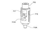
- the piston 715 is urged in a radial direction orthogonal to the axial direction by a coil spring 716, and a protrusion 715A at the tip protrudes into a through hole 712A serving as an insertion path for the treatment instrument 504A.
- a slit 717 is formed in the piston 715, and an engagement piece 717 ⁇ / b> A is formed in the slit 717.
- a first groove 718 of a connecting plate 713 inserted from a slit 712C penetrating the ratchet base 712 is engaged with the engaging piece 717A.
- the piston 715 may be provided with a longitudinal groove 717C parallel to the radial direction.
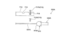
- the connecting plate 713 is connected to the second bending slider 711 by a fulcrum pin 721 at the distal end side, and extends substantially parallel to the axis from here toward the ratchet base 712.
- the first groove 718 has a concave shape into which the engagement piece 717A of the piston 715 can enter, and the wall surface on the distal end side of the first groove 718 is an inclined surface 718A from the middle. By the inclined surface 718A, the width of the first groove 718 is gradually expanded from the middle to the tip side.
- a second groove 719 is carved further on the tip side than the first groove 718.
- the second groove 719 has a concave shape into which the engagement piece 717A of the piston 715 can enter.
- the depth of the second groove 719 is shallower than that of the first groove 718.
- a wall surface on the proximal end side of the second groove 719 is an inclined surface 719A.
- the width of the second groove 719 is gradually expanded toward the base end side by the inclined surface 719A.
- the first groove 718 is formed at a position where the second curved portion 308 of the first arm portion 302A shown in FIG. 1 is straight.
- the second groove 719 is formed at a position where the second bending portion 308 is bent to open the first arm portion 302A. Therefore, when the first groove 718 is engaged with the piston 715, the arm portion 302A is closed, and when the second groove 719 is engaged, the second arm portion 303A can be opened.
- the second bending slider 711 is disposed coaxially with the axis of the operation stick 531A.
- the first operation unit 530A becomes compact.
- An edge 711A for hooking fingers is formed on the base end side.
- a linear stroke 722 is built in a portion in contact with the shaft 701 so that it can slide smoothly with respect to the shaft 701.
- pipes 731 are attached to the front end side of the second bending slider 711 one by one on the left and right sides with the axis line therebetween.
- the second bending wires 316A and 316B are passed through the pipes 731 one by one.
- the second bending wires 316A and 316B are fixed to the locking member 732 in the second bending slider 711, and the second bending wires 316A and 316B are prevented from coming off from the second bending slider 711.
- the pipes 731 are further inserted one by one into the two shafts 702 and 703 on the distal end side.
- the side shafts 702 and 703 into which the pipe 731 and the second bending wires 316A and 316B are inserted have a receiving member 741 on the base end side.
- Another pipe 742 is inserted into the receiving member 741 from the distal end side, and the pipe 731 and the second bending wires 316A and 316B are passed through the pipe 742.
- the tip of the pipe 742 is supported by the coil receiving case 743.
- the coil receiving case 743 is screwed into the hole of the cylindrical pusher 744.
- One end of a coil spring 745 is brought into contact with the proximal end of the pusher 744.
- the other end of the coil spring 745 is abutted against the receiving member 741, and the pusher 744 is urged toward the distal end side by the coil spring 745.
- a force is applied so that the coil sheath 747 moves relatively to the proximal side, and the coil spring 745 is compressed via the pusher 744. If the coil spring 745 is set in a state compressed in advance to a length that generates a predetermined force, the coil spring 745 starts to contract when the predetermined force is exceeded.
- the second bending wires 316A and 316B can be further pulled as much as the coil spring 745 contracts, an excessive force is not applied to the second bending wires 316A and 316B. Further, even when an excessive force is applied, while the coil spring 745 can be contracted, the force applied to the second bending wires 316A and 316B does not increase rapidly, and the overload amount is suppressed, so that it does not break.
- the coil spring 745 is compressed by a pusher pressing member 746 that is screwed from the distal ends of the shafts 702 and 703. Since the initial position of the pusher 744 can be adjusted by the pushing amount of the pusher pressing member 746, individual differences in the strength of the coil spring 745 and individual differences in the amount of force necessary for bending can be adjusted.
- the second bending wires 316A and 316B are drawn from the pipe 742.
- the second bending wires 316 ⁇ / b> A and 316 ⁇ / b> B are inserted into the coil sheath 747 within the coil receiving case 743, introduced into the connection sheath 515 together with the coil sheath 747, and routed to the second bending portion 308.
- the proximal end of the coil sheath 747 is fixed to a pipe-shaped coil receiver 748 within the coil receiver case 743 by brazing or the like.
- a coil receiving holding member 749 is screwed into the coil receiving case 743 from the distal end side.
- the coil receiver holding member 749 locks the coil receiver 748 in a freely rotatable manner, the coil sheath 747 does not come out of the coil receiver case 743 and the coil sheath 747 is not twisted.
- An assembly error may occur in the relative lengths of the coil sheath 747 and the second bending wires 316A and 316B, or the second bending wires 316A and 316B may extend and an error may occur.
- the error can be adjusted by adjusting the screwing amount of the coil receiving case 743 to the pusher 744.
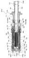
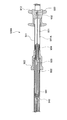
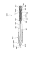
- a channel 801 through which the treatment instrument 504 ⁇ / b> A is passed is built in the central shaft 701.
- the channel 801 includes, from the proximal end side, a receiving portion 802 that receives the treatment instrument 504A, a coil spring 803 that is inserted between the receiving portion 802 and the distal end portion 571A, and a telescopic pipe 804 that is disposed in the coil spring 803. And have.
- the receiving portion 802 is formed with a hole 802A at the center which serves as an entrance when the treatment instrument 504A is passed.
- the hole 802A has a tapered shape in which the opening diameter on the base end side is increased.
- the telescopic pipe 804 has three pipes 805, 806, and 807 having different diameters arranged on the same axis, and a retaining member 808 is attached to the pipes 805 and 806.
- a stopper 809 is attached to the pipes 806 and 807 so as to be locked to the stopper 808. That is, when the three pipes 805 to 807 substantially overlap, the telescopic pipe 804 is the shortest. When the pipes 805 to 807 are stretched until the stopper 809 is locked to the stopper 808, the telescopic pipe 804 is the longest.
- the coil spring 803 is shown in a compressed state, the coil spring 803 is restored in a no-load state, and the receiving portion 802 moves near the proximal end of the shaft 701 to near the distal side of the piston 715.
- the receiving portion 802 In a state where the treatment instrument 504A is not inserted, the receiving portion 802 is disposed at the proximal end of the shaft 701, so that the insertion portion 507A of the treatment instrument 504A can be easily inserted.
- the receiving portion 802 is pushed forward by the distal end portion of the operation portion 506A of the treatment instrument 504A when the treatment instrument 504A is inserted, and is moved to the position shown in FIG.
- the telescopic pipe 807 is not limited to a triple pipe structure.
- An airtight valve 811 is provided in the path through which the treatment tool 504A is inserted, so that airtightness inside the body is maintained even if the treatment tool 504A is removed during the operation.
- the airtight valve 811 is made of, for example, a rubber sheet disposed so as to seal the hole 571 ⁇ / b> B communicating with the shaft 701.
- the rubber sheet is provided with a cut capable of inserting the insertion portion of the treatment instrument 504A. When passing the treatment tool 504A, the cut is pushed open. When the treatment instrument 504A is removed, the cut is closed and airtightness is maintained.
- a pressing member 812 is used to fix the airtight valve 811. If the holding member 812 is fixed to the distal end portion 571A with a screw, the airtight valve 811 made of a rubber sheet can be easily replaced.
- the treatment instrument 504A is introduced into the body through the hole 812A formed in the pressing member 812. However, the treatment tool 504A can be easily inserted by tapering the hole 812A toward the distal end side. Yes.
- the configuration of the second operation unit 530B will be described.
- the second operation unit 530B has a configuration symmetrical to the first operation unit 530A with respect to the center line in the left-right direction of the operation unit 520.
- “B” is given to some of the reference numerals in order to distinguish them from the first operation unit 530A.
- the treatment tool 504A to be inserted into the operation unit 520 will be described. Only the treatment instrument 504A will be described, but the treatment instrument 504B has the same configuration.
- One of the treatment instruments 504A and 504B may be a high-frequency knife, a puncture needle, a snare, a clip, other forceps, or the like.
- the treatment instrument 504A has a configuration in which a distal treatment portion 505A (see FIG. 1) and an operation portion 506A are connected by a long and flexible insertion portion 507A.
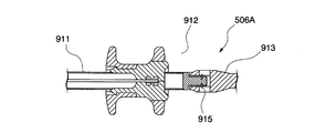
- the operation portion 506A has a main body portion 911 having a cam 910 fixed to the distal end, and a slider 912 for driving the treatment portion 505A is attached to the base end side of the main body portion 911 so as to be able to advance and retreat in the axial direction.
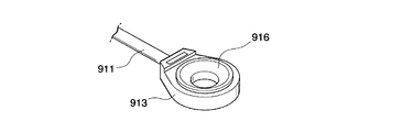
- a finger ring 913 is attached to the base end of the main body 911.
- the ring 913 is connected to the main body portion 911 via an E ring 915. Since the ring 913 can be rotated around the axis via the E-ring 915, the operability is good.
- a rubber protective member 916 may be fitted inside the ring 913 for use.
- the protective member 916 has a groove 916 ⁇ / b> A on the outer periphery, and is detachable from the ring 913. Fingers do not hurt during operation by using rubber. Moreover, since it is a detachable structure, it is excellent in cleaning property and sterilization property. If the protective member 916 is made of, for example, silicone rubber, chemical resistance and sterilization resistance can be provided.
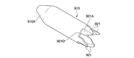
- the cam 910 has a tip that is reduced in diameter by a taper.
- the tapered surface 910A has a role of pushing up the piston 715 and a role of pushing in the channel 801 when inserted into the operation stick 531A.
- the outer periphery of the cam 910 is slidable substantially equal to the inner diameter of the shaft 701.
- the base end portion of the cam 910 has four wing portions 921 extending in the axial direction extending at equal intervals in the circumferential direction. As shown in FIG. 90A, each wing portion 921 is provided only on the outer peripheral portion of the cam 910, and one side surface 921A in the circumferential direction is inclined while forming a curved surface from the center side toward the radially outer side. Yes.
- a slope 921 ⁇ / b> C may be provided on the outer peripheral side of the inclined side surface 921 ⁇ / b> A of the cam 910 along with the step surface 921 ⁇ / b> B rising in the radial direction.
- the side surface 921A inclined by the slope 921C and the step 921D on the outer periphery of the cam 910 are smoothly eliminated.
- the side surface 921E opposite to the side surface 921A forms a gap slightly larger than the diameter of the piston 715 between the side surface 921A of the other wing portion 921 adjacent in the circumferential direction.
- the side surface 921E is inclined in the same direction as the inclination direction of the side surface 921A, and is a steep slope having a large inclination angle.
- the main body 911 is fixed to the inner hole of the cam 910 by screwing.
- the outer diameter of the main body 911 may be gradually decreased toward the base end side from the portion inserted into the cam 910 to the stopper 922 having an enlarged diameter. That is, FIG. 15 shows an example in which the diameter d2 on the base end side is smaller than the diameter d1 on the front end side. This is to prevent the main body portion 911 from pushing up the piston 715 even when there is play in the dimensions of the operation portion 506A of the treatment instrument 504A with respect to the operation stick 531A and the operation portion 506A is tilted or bent. It is.
- the relationship is set such that there is a gap between the piston 715 and the piston 715 when the tip of the piston 715 protrudes into the shaft 701. Interference between the piston 715 and the main body 911 is prevented, and the advancement / retraction of the treatment instrument 504A is lightened.
- the stopper 922 abuts on the ratchet base 712 when the treatment instrument 504A is inserted into the operation stick 531A, and restricts the treatment instrument 504A from being pushed in first.
- a pipe 931 is fixed to the slider 912, and an operation wire 932 for driving the treatment section 505A is passed through the pipe 931.
- the proximal ends of the operation wire 932 and the pipe 931 are locked to the slider 912 by a locking member 933.
- the pipe 931 passes through the slit 911 ⁇ / b> A of the main body portion 911 and is supported by a resinous pipe receiver 934 so as to freely advance and retract.
- the operation wire 932 is pulled out through another pipe 935 fixed to the pipe receiver 934, enters the intermediate jumper 941 together with the pipe 935, and is inserted into the metal single-layer coil 942 therein.
- the pipe 935 is insulated by being covered with a heat shrinkable tube.
- a coil receiver 943 to which the base end of the single layer coil 942 is fixed is accommodated on the base end side of the intermediate collar 941.
- the tip of the pipe 935 is inserted into the coil receiver 943.
- the intermediate collar 941 is provided with a reduced diameter portion 941A that prevents the coil receiver 943 from being pulled out to the tip side.
- the single layer coil 942 is inserted into the multilayer coil 951 on the tip side from the reduced diameter portion 941A.
- the multilayer coil 951 has a configuration in which three or more coils are coaxially arranged.
- the winding direction of the innermost layer coil and the outermost layer coil are made the same, and the winding direction of the intermediate layer coil is reversed.
- the intermediate layer coil is tightened, and the intermediate layer and innermost layer coils interfere to transmit the rotational torque to the treatment section 505A at the distal end.
- the loosened intermediate layer coil and the tightened outermost layer coil interfere with each other, and the rotational torque is transmitted to the treatment portion 505A.
- the multilayer coil 951 is made of metal, the transmission performance of the rotational torque is improved. If it is necessary to consider insulation, it is better to use a resin coil.
- the coil receiver 952 is brazed to the multilayer coil 951.
- the coil receiver 952 is slidably inserted into a long groove 941B carved in an insulating intermediate tab 941. For this reason, the multilayer coil 951 and the intermediate lever 941 engage in the rotational direction, but do not engage in the forward / backward direction.
- a resin stopper 953 is attached to the distal end side of the intermediate bush 941, and the stopper 953 restricts the protrusion of the coil receiver 952, so that the multilayer coil 951 does not come out of the intermediate bush 941. Absent. Further, the coil receiver 952 does not come into contact with the main body 911. With this configuration, the length of the multilayer coil 951 is not affected even if the single-layer coil 942 contracts or expands during treatment.
- the multilayer coil 951 is brazed in a state where the coil receiver 943 is slid to the base end side and pulled out from the intermediate tab 941. can do.
- the intermediate jumper 941 becomes high temperature during brazing, it is desirable to manufacture the intermediate jumper 941 with a resin having high heat resistance such as PEEK (polyether ether ketone).
- the outer periphery of the multilayer coil 951 drawn out from the intermediate bush 941 is covered with an insulating tube 954.
- the insulating tube 954 is made of a fluororesin, the sliding resistance is small and the rotation is good.
- the multilayer coil 951 with insulation coating passes through the pipe 955 that prevents meandering, and is then drawn out from a hole 910 ⁇ / b> C formed at the tip of the cam 910.
- the main body portion 911 In consideration of durability, it is preferable to manufacture the main body portion 911 from a metal material.
- a treatment instrument 504A that performs treatment using high frequency can be realized.
- the stopper 953, the intermediate collar 941, the heat shrinkable tube of the pipe 935, the pipe receiver 934, and the slider 912 made of resin, the gap between the main body 911, the operation wire 932, and the coils 942 and 951 can be reduced. Insulation is secured.
- treatment implement 504A can also be used in the type which applies a high frequency like an incision knife, a high frequency forceps, etc., or can be used together.
- the insulation coating of the multilayer coil 951 does not have to be provided if it is not a treatment instrument that applies high frequency. In this case, if the thickness of the heat-shrinkable tube used for coating is used to increase the thickness of the multilayer coil 951, a treatment tool with better rotation can be obtained. If the thickness is applied to the single-layer coil 942, it becomes stronger against compression and elongation.
- Two treatment tools 504A and 503B are inserted into the treatment endoscope 501.
- the treatment tool 504A is inserted into the first operation unit 530A.
- the piston 715 provided on the ratchet base 712 at the base end of the first operation stick 531A is engaged with the first groove 718 of the connecting plate 713.
- the connecting plate 713 is locked together. Since the ratchet base 712 cannot move, the movement of the second bending slider 711 is prohibited by the connection plate 713 being locked.
- the position at this time is a position where the second bending portion 308 is straight.
- the second bending portion 308 is always straight when the treatment instrument 504 ⁇ / b> A is inserted.
- the piston 715 is pushed up by the tapered surface 910A of the cam 910 at the tip of the operation unit 506A.
- the second bending slider 711 can be operated in the direction indicated by the arrow. .
- the insertion portion 507A of the treatment instrument 504A passes through the channel 801 and is guided to the channel in the connection sheath 515. Furthermore, it passes through the endoscope operation unit 502 and the endoscope insertion unit 503 and is guided to the tip of the first arm unit 302A. Similarly, the treatment instrument 504B is also inserted from the second operation stick 531B of the second operation unit 530B and guided to the tip of the second arm portion 303A.
- the endoscope insertion portion 503 is introduced into the body cavity from the opening formed in the stomach wall in advance with the two arm portions 302A and 303A closed. At this time, it may be passed through an overtube previously inserted into the body.
- the part to be treated is confirmed while observing an endoscopic image acquired by an imaging device provided at the tip of the endoscope insertion unit 503 on a monitor (not shown).
- the first operator operates the angle knob 512 of the endoscope operation unit 502 to bend the third bending portion 203B.
- the second operator also curves the second bending portion 308 and the first bending portion 306 as necessary.
- the second bending slider 711 When the second bending portion 308 is bent, the second bending slider 711 provided on the operation sticks 531A and 531B is moved backward. As shown in FIG. 25, when the second bending slider 711 is retracted while the piston 715 is lifted, the locking piece 717A of the piston 715 rises on the inclined surface 718A, and as shown in FIG. 713 slides on the piston 715. As shown in FIG. 27, when the piston 715 is fitted in the second groove 719, the second bending slider 711 cannot be moved backward any more. In this position, the second bending portion 308 shown in FIG. 1 is bent and the first arm portion 302A is opened.
- the second groove 719 is shallower than the first groove 718, and when the piston 715 is engaged with the second groove 719, a gap Ss is formed between the main part 911 of the operation unit 506A. ing. Since the main body 911 and the piston 715 are not rubbed, the main body 911 can be smoothly advanced and retracted.
- the operation portions 506A and 506B of the treatment tools 504A and 504B are tilted while confirming the endoscopic image.
- the rotation shafts 564A and 565A of the first rotation mechanism 561A rotate according to the tilt angle.
- the sprocket 595 attached to each of the rotation shafts 564A and 565A rotates and the first bending wires 315A and 315B attached to the chain 622 are pushed and pulled, so that the first bending portion 306 is bent upward.
- the rotation shafts 564A and 565A of the first rotation mechanism 561A rotate in the opposite direction according to the tilt angle.
- the sprocket 595 attached to each of the rotation shafts 564A and 565A rotates in the reverse direction, and the first bending wires 315A and 315B attached to the chain 622 are pushed and pulled in the opposite direction, and the first bending portion 306 is moved downward. Bend.
- the rotation shafts 584A and 585A of the second rotation mechanism 581A rotate according to the tilt angle.
- the sprocket 595 attached to each of the rotation shafts 584A and 585A is rotated so that the first bending downward operation wire and the first bending upward operation wire attached to the chain 622 are pushed and pulled, and the first bending portion 306 is moved rightward. Bend.
- the rotation shafts 584A and 585A of the second rotation mechanism 581A rotate in the reverse direction according to the tilt angle.
- a sprocket 595 attached to each of the rotation shafts 584A and 585A rotates in the reverse direction, and the first bending downward operation wire, the first bending upward operation wire attached to the chain 622, and the first bending portion 306 are bent leftward. To do.
- the operation unit 506A is tilted obliquely, the first and second rotating mechanisms 561A and 581A are driven according to the ratio between the vertical direction and the horizontal direction, and the first bending unit 306 tilts the operation unit 506A. Curved diagonally in the same direction as the direction.
- the operation stick 531A and the treatment can be performed even if the operator releases the hand.
- the operation unit 506A of the tool 504A does not drop downward due to gravity, and malfunction is prevented.
- the operation of the first bending portion 306 is a wire operation without using electrical means, the force required for the operation is adjusted to an appropriate value.
- the operation portion of the operation stick 531A for inputting force by the operator is separated from the rotation shafts 564A, 565A, 584A, 585A and offset to reduce the speed.
- a speed reduction ratio corresponding to the ratio of the distance Lr from the proximal end portion of the operation portion 506A of the treatment instrument 504A to the rotation shafts 564A, 565A, 584A, 585A and the radius Rs of the sprocket 595 is obtained. Therefore, the bending operation can be performed with a small amount of force while the size of the operation unit 520 is reduced. In addition, the reduced speed increases the resolution and enables a precise bending operation.
- the position where the force is transmitted from the first operation stick 531A to the second rotation mechanism 581A is the tip of the rotation shafts 564A and 565A as in the roller bearing 572A shown in FIG. Since the position is offset to the side, the amount of force at the transmission position is reduced and friction between parts is reduced. The strength required for the component parts can be reduced, and the operation unit 520 can be reduced in size and weight. Further, since the ball roller 572A is used at the position of transmitting force from the first operation stick 531A to the second rotation mechanism 581A, friction with the second rotation mechanism 581A is caused when the first operation stick 531A is rotated up and down. Is reduced, and the amount of force required for the up / down operation can be reduced.
- the position of the forceps member to be opened / closed is adjusted by the operation unit 506A of the treatment instrument 504A.
- the operation unit 506A When grasping the tissue, the position of the forceps member to be opened / closed is adjusted by the operation unit 506A of the treatment instrument 504A.
- the operation unit 506A When grasping the tissue, the position of the forceps member to be opened / closed is adjusted by the operation unit 506A of the treatment instrument 504A.
- the operation unit 506A is pushed into the first operation stick 531A, the treatment unit 505A further protrudes from the first arm unit 302A.
- the treatment unit 505A is pulled out from the first operation stick 531A.
- the treatment unit 505A is pulled into the first arm unit 302A.
- the treatment instrument 504A does not inadvertently come out of the first operation stick 531A.
- the main body 911 of the operation unit 506A When adjusting the direction of the treatment instrument 504A around the axis, the main body 911 of the operation unit 506A is rotated around the axis. Rotational torque is input to the multilayer coil 951 that is engaged in the rotational direction with the intermediate tab 941 shown in FIGS. Depending on the combination of the winding direction of each coil of the multilayer coil 951 and the rotation direction of the operation unit 506A, the coil is tightened or loosened, and two coils arranged adjacent to each other in the radial direction interfere with each other, and rotational torque is transmitted. The Since the treatment portion 505A is fixed to the distal end of the multilayer coil 951, the treatment portion 505A rotates about the axis by the transmission of the rotational torque. After confirming that the desired orientation is obtained from the endoscopic image, the rotation on the hand side is stopped.
- the slider 912 After adjusting the orientation and position of the treatment section 505A, the slider 912 is advanced.
- the operation wire 932 operates the opening / closing mechanism of the treatment portion 505A to open the pair of gripping pieces.
- the single layer coil 942 receives the extending force generated by pushing the operation wire 932. Since the multilayer coil 951 is not engaged with the operation portion 506A in the forward / backward direction, no force is applied to the multilayer coil 951. For this reason, the orientation of the treatment portion 505A can be adjusted even when the gripping piece is opened.
- the slider 912 When the slider 912 is retracted, the grasping piece is closed and the tissue is grasped. The compressive force generated at this time is received by the single layer coil 942.
- the treatment tools 504A and 505B are removed from the treatment endoscope 501. Further, the treatment tools 504A and 505B are also removed from the treatment endoscope 501 when a necessary treatment tool is replaced during the treatment.
- the operation unit 506A is rotated around the axis.
- the piston 715 is pushed up along the inclined side surface 921A of the wing portion 921 of the cam 910. By providing the inclined side surface 921A, the piston 715 can be pushed up with a small force as shown in FIG.
- the treatment instrument 504A does not rotate too much.
- the cam 910 is preferably made of metal in order to prevent breakage.
- the first operation stick 531A may be manufactured from POM (polyoxymethylene) having good slipperiness so that the cam 910 can be easily advanced and retracted.
- the treatment portions 505A and 504B cannot be removed if the second curved portion 308 of the arm portions 302A and 303A is open.
- the second bending portion 308 automatically returns to the straight. That is, when the piston 715 is lifted and the engagement with the second groove 719 is released, the second bending slider 711 is pulled back by the tension of the second bending wires 316A and 316B and the restoring force of the coil spring 745. As a result, the second bending portion 308 returns straight.
- an elastic member such as a spring 792 in FIG. 13 may be added in order to prevent the second bending slider 711 from returning vigorously. Then, after removing the treatment instrument 504A, the treatment endoscope 501 is removed from the body.
- the operation units 1001A and 1001B for operating the second bending slider 711 may be fixed to the brackets 551A and 551B one by one in parallel with the respective axes of the operation sticks 531A and 531B.
- Each operation unit 1001A, 1001B has a slider that can be moved forward and backward, and when the slider is moved, the wire in the coil sheath 1002 moves forward and backward.
- the coil sheath 1002 is fixed to a coil receiver 1003 attached to the ratchet base 712.
- a pipe 1004 is passed through the coil receiver 1003.
- the pipe 1003 is passed through the coil sheath 1002 and is rotatably engaged with the second bending slider 711 via the wire receiver 1005 together with the second bending wires 316A and 316B.
- a wire 1006 connected to the sliders of the operation units 1001A and 1001B is passed through the pipe 1004.
- the wire 1006 moves, the second bending slider 711 is pulled, and the second bending portion 308 is opened.
- the operation unit 520 can be made compact, and the second bending unit 308 can be easily operated.
- the operation sticks 531A and 531B do not move when the second bending portion 308 is operated. The grasped tissue does not move unexpectedly.
- the base end side of the cam 910 may be an inclined surface 1010.
- the treatment instrument 504A is pulled from the first operation stick 531A, the treatment instrument 504A is removed after the piston 715 has moved up the inclined surface 1010. The force of pulling the treatment tool 504A toward the hand during the treatment will not accidentally come off. You can remove it by applying more force. In this configuration, the treatment instrument 504A can be removed without rotating the operation unit 506A.
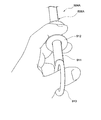
- FIG. 33 the slider 912 is sandwiched between the index finger and the middle finger.
- the slider 912 is rotated 90 ° clockwise with the slider 912 interposed therebetween.
- the index finger and the middle finger are separated from the slider 912. While releasing the hand from the slider 912, the hand is rotated 90 ° counterclockwise to the position shown in FIG.
- the insertion portion 507A of the treatment instrument 504A is connected to the channel from the first operation stick 531A to the second arm portion 302A, that is, the channel 801, the channel in the connection sheath 515, and the channel of the endoscope insertion portion 503. Therefore, even if the slider 912 and the finger touch each other slightly, it does not rotate counterclockwise and maintains its positional relationship. By repeating the above procedure, the treatment instrument 504A can be fed by 90 °.
- the treatment endoscope 501 may be used through the overtube 90.
- the first operator of the endoscope operation unit 502 performs a normal endoscope operation with the left hand, and operates the endoscope insertion unit 503 and the overtube 90 with the right hand.
- the curve of the overtube 90 By using the curve of the overtube 90, the approachability to the target position within the abdominal cavity is improved.
- the treatment endoscope of the present embodiment has the same basic structure as the above-described example, and a wire that transmits the operation of the operation unit to the arm unit that performs the treatment and the operation unit are detachable. .
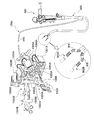
- FIG. 36 is a diagram showing a configuration of the treatment endoscope 1300 of the present embodiment.
- the treatment endoscope includes an endoscope operation unit 502 and an endoscope insertion unit 503 that are the same as those in the first embodiment, and an operation unit 1350 that has substantially the same basic structure as the operation unit 520.
- two arm portions 302A and 302B extend from the endoscope insertion portion 503.
- An observation device (not shown) is attached to the tip of the protruding sheath 301 so that the arms 302A and 302B can be observed.
- a wire for transmitting the operation of the operation unit 1350 to the arm units 302A and 302B is connected to a wire unit (mounting unit) that is detachable from the operation unit 1350 through the connection sheath 515.
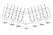
- the wire unit has two first bending wire units, that is, a first wire unit 1301 for moving up and down, a second wire unit 1302 for moving left and right, and a second wire unit for bending.
- a total of 1303 is provided. Therefore, in the present embodiment, a total of six wires, each of the wire units 1301A, 1302A, and 1303A connected to the first arm portion 302A and each of the wire units 1301B, 1302B, and 1303B connected to the second arm portion 302B.
- a unit is provided.
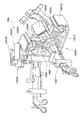
- FIG. 37 shows the operation unit 1350.
- the operation unit 1350 has substantially the same structure as the operation unit 520 of the first embodiment, and the first operation unit 1350A for operating the first arm unit 302A and the second operation unit for operating the second arm unit 302B. 1350B.
- the first wire units 1301A and 1301B are attached to the first rotation mechanisms 1351A and 1351B (not shown) of the operation units 1350A and 1350B, respectively.
- the second wire units 1302A and 1302B are attached to second rotation mechanisms 1352A and 1352B (not shown) of each operation unit.
- the second bending wire units 1303A and 1303B are detachably attached to second bending operation mechanisms 1353A and 1353B (not shown) provided between the first rotation mechanism and the second rotation mechanism in each operation unit. It is attached.
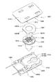
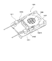
- FIG. 38 is a perspective view showing the first wire unit 1301
- FIG. 39 is an exploded view showing the first wire unit 1301.
- the second wire unit 1302 has the same structure except that the connected wires are different.
- the first wire unit 1301 includes a coil 1304 through which a wire extending from the arm portion is inserted, a coil base 1305 to which the coil 1304 is fixed, and a coil base 1305 through which the wire is inserted.
- a pulley (mounting member) 1306 that is wound around, a wire cover 1307 that is rotatably attached to the pulley 1306, and a unit cover 1308 that is attached to the coil base 1305 are configured.
- FIG. 40 is a view showing the first wire unit 1301 excluding the unit cover 1308 and the wire cover 1307.
- the coil base 1305 is formed of resin or the like, and includes a base portion 1309 to which each mechanism is attached, and a protrusion (first protrusion) 1310 provided to extend downward from the base portion 1309.
- a coil 1304 is fixed to the left and right of one end via a fixing member 1311.
- FIG. 41 is a cross-sectional view of the pulley 1306 inserted through the base portion 1309.
- the pulley 1306 has a disk part 1312 around which a wire extending from the arm part is wound, and a mounting part (second protrusion) 1313 extending below the disk part 1312.
- the mounting portion 1313 is provided below the disk portion 1312, and is provided below the first mounting portion 1313A having a smaller diameter than the disk portion 1312 and the first mounting portion 1313A, and has a diameter smaller than that of the disk portion 1312.
- a second mounting portion 1313B having a larger diameter than the first mounting portion 1313A.
- the pulley 1306 is disposed with a mounting portion 1313 rotatably inserted in a hole portion 1314 provided in a base portion 1309 of the coil base 1305.
- the hole 1314 is a groove having a width larger than the diameter of the circular mounting hole 1314A having a larger diameter than the second mounting portion 1313B and the first mounting portion 1313A and smaller than the diameter of the second mounting portion 1313B. 1314B.
- the disk portion 1312 is located on the base portion 1309, and the mounting portion 1313 protrudes below the base portion 1309.
- the pulley 1306 is arranged such that the first mounting portion 1313A is positioned in the groove 1314B.
- the wires 315C and 315D connected to the arm portion are inserted through the coil 1304 and protrude from the left and right fixing members 1311.
- Each of the wires 315C and 315D is wound around the outer periphery of the disk portion 1312 and is inserted into the disk portion 1312 from the end of the disk portion 1312 opposite to the fixing member 1311.
- a groove 1312A is provided on the upper surface of the disk portion 1312, and ends of the wires 315C and 315D are exposed in the groove 1312A.
- the ends of the wires 315C and 315D are fixed to the disk portion 1312 by a wire fixing member 1315.
- the wires 315C and 315D are integrally connected to the pulley 1306.
- the arm portions 302A and 302B are appropriately determined so that they can be appropriately operated.
- a substantially disc-shaped wire cover 1307 is attached from above the pulley 1306, and the wire fixing member 1315 is pressed by the wire cover 1307. Since the diameter of the wire cover 1307 is larger than the disk portion 1312 of the pulley 1306 and has side surfaces in the circumferential direction, the outside of the wires 315C and 315D wound around the pulley 1306 is covered with the wire cover 1307.
- the wire cover 1307 is formed with a notch 1307A through which the wire passes and a flat portion 1307B that comes into contact with the coil base 1305.
- the wires 315C and 315D protruding from the fixing member 1311 are wound around the pulley 1306 through the notch 1307A.
- the flat portion 1307B is in contact with the protrusion 1305A formed on the coil base 1305. Accordingly, the rotation of the wire cover 1307 is restricted, and the wire cover 1307 does not rotate even when the pulley 1306 rotates. Therefore, the position of the notch 1307A does not change, and the wire 315C, 315D and the wire cover 1307 are prevented from contacting each other while maintaining the positional relationship with the fixing member 1311.
- the unit cover 1308 includes a main body 1316 larger than the base portion 1309 of the coil base 1305 and four engaging claws 1317 provided so as to extend downward from the vicinity of the periphery of the main body 1316. It is configured.
- the unit cover 1308 is integrated with the coil base 1305 by being attached from above the base portion 1309 so that the four engagement holes 1318 provided in the base portion 1309 and the engagement claws 1317 are engaged with each other.
- the cover 1307 is prevented from floating.
- the engagement claw 1317 and the engagement hole 1318 are kept in the engaged state, and the engagement claw 1317 has a predetermined length in the engagement hole 1318 in the width direction and the longitudinal direction of the coil base 1305, for example, several millimeters. Play is provided so that it can be moved to some extent. Therefore, the unit cover 1308 can be moved relative to the coil base 1305 by a predetermined length in the width direction and the longitudinal direction of the coil base 1305 while being integrated with the coil base 1305.
- FIG. 43 is a diagram showing the first mounted unit 1354 provided in the first wire unit 1301 and the first rotation mechanism 1351 of the operation unit 1350.
- the first wire unit 1301 is attached to the first mounted portion 1354 with a drape 1319 in between in order to prevent contamination. This attachment procedure will be described later.
- FIG. 44 is a cross-sectional view of FIG. Below the first wire unit 1301, a protruding portion 1310 of the coil base 1305 and a mounting portion 1313 of the pulley 1306 protrude.
- Each of the protruding portion 1310 and the mounting portion 1313 has a substantially cylindrical shape, and is formed in a tapered shape in which the tip is gradually narrowed. A part of the outer peripheral surface excluding the tapered tip is cut, and second outer peripheral surfaces 1310A and 1313C parallel to the axis of the mounting portion 1313 are formed.
- the cross section perpendicular to the axis through the second outer peripheral surface is D-shaped in both the protruding portion 1310 and the mounting portion 1313.
- the second outer peripheral surfaces 1310A and 1313C are respectively provided with fitting holes 1320A and 1320B for fitting with the first mounted portion 1354 toward the radially inner side.
- the fitting hole 1320A is provided so as to open to the coil 1304 side, but may be provided in a different direction.
- the fitting hole 1320B of the mounting portion 1313 changes its direction with the rotation of the pulley 1306. As shown in FIG. 44, in the state where the fitting hole 1320B opens on the opposite side to the coil 1304, the arm portion Are connected to the pulleys 1306 and the wires 315C and 315D so as to be in an initial state parallel to the axis of the insertion portion of the endoscope.
- each of the fitting holes 1320A and 1320B has a shape in which the openings in the second outer peripheral surfaces 1310A and 1313C are long in the axial direction of the protruding portion 1310 and the mounting portion 1313, and each of the fitting holes 1320A and 1320B has a protruding portion. 1310 and the mounting portion 1313 are processed into a tapered shape so as to become shallower as they approach the tip. When the taper angle of each of the fitting holes 1320A and 1320B is set to around 30 to 40 degrees, the balance between the mounting strength and the ease of removal becomes good.
- the first mounted portion 1354 includes a first insertion portion 1355 into which the protruding portion 1310 is inserted, a second insertion portion 1356 into which the mounting portion 1313 is inserted, and a protruding portion that is rotatably attached to the first inserting portion 1355.
- a first holding portion 1357 that detachably and integrally holds 1310 and the first insertion portion 1355; and a second holding portion 1358 that detachably and integrally holds the mounting portion 1313 and the second insertion portion 1356. It is configured.
- the first insertion portion 1355 includes a flat base portion 1359 and a substantially cylindrical insertion hole 1360 attached to the base portion 1359 so as not to rotate.
- the second insertion portion 1356 has a substantially cylindrical shape, and is attached to a hole 1359 ⁇ / b> A provided in the base portion 1359 via a bearing 1361. That is, the second insertion portion 1356 is rotatable with respect to the base portion 1359.
- the second insertion portion 1356 is connected to the rotation shaft of the first rotation mechanism 1351 and rotates in conjunction with rotation of the rotation shaft.
- end surface of the insertion hole 1360 and the second insertion portion 1356 on the base portion 1359 side is chamfered to facilitate the insertion of the projection portion 1310 and the mounting portion 1313.
- the first holding portion 1357 and the second holding portion 1358 have substantially the same structure, and are accommodated in the fixing portions 1362A and 1362B fixed to the insertion hole 1360 and the second insertion portion 1356, respectively, and the fixing portion 1362. It has fitting members 1363A and 1363B.
- the second holding unit 1358 will be described, but the configuration and operation thereof are substantially the same for the first holding unit 1357 as well.
- the fixing portion 1362B of the second holding portion 1358 is a substantially cylindrical member, and is attached to the outer surface of the second insertion portion 1356 so that the axes thereof are orthogonal to each other.
- the operation amount of the first rotation mechanism 1351 is set to an initial state of zero.
- the fitting member 1363B is a substantially cylindrical member having a smaller diameter than the fixed portion 1362B, and is accommodated in the fixed portion 1362B.
- a biasing member 1364B such as a spiral spring is interposed between the fixed portion 1362B and the fitting member 1363B, and biases the fitting member 1363B toward the second insertion portion 1356.
- the wall surface of the portion where the fixing portion 1362B of the second insertion portion 1356 is attached is cut, and the fitting member 1363B protrudes into the second insertion portion 1356 by a predetermined length by the urging force of the urging member 1364B. It is like that.
- a fitting protrusion 1365B having a shape that can be fitted into the fitting hole 1320B is provided at the tip of the fitting member 1363B.
- the outer peripheral surface of the mounting portion 1313 where the fitting hole 1320B is provided has the flat second outer peripheral surface 1313C.
- the second outer peripheral surface 1313C in the vicinity of the arc-shaped outer periphery 1313D of the mounting portion 1313 is formed in a curved surface so as to be slightly convex outward in the radial direction.
- the fitting member 1363B A part of the applied urging force F is disassembled in a tangential direction with respect to the outer periphery 1313D of the mounting portion 1313, and acts as a torque T that rotates the mounting portion 1313 in a direction in which the fitting hole 1320B and the fitting protrusion 1365B approach.
- the mounting portion 1313 rotates, and the fitting hole 1320B and the fitting protrusion 1365B are fitted to face each other as shown in FIG. 46, and the second insertion portion 1356 and the mounting portion 1313 are integrally held. .
- the second holding portion 1358 is rotated by the reaction force of the torque T in addition to the mounting portion 1313 being rotated by the torque T.
- the 2nd insertion part 1356 also rotates to some extent.
- the fitting hole 1320B and the fitting protrusion 1365B are fitted to face each other.
- the protrusion 1310 and the first insertion portion 1355 of the coil base 1305 are integrally held in the same manner, but the insertion hole 1360 is not rotatable with respect to the base portion 1359, and thus the relative rotation as described above.
- the fitting hole 1320A and the fitting protrusion 1365A are fitted with each other without occurring.
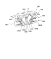
- FIG. 47 is a view showing the second bending wire unit 1303 excluding the unit cover 1308 and the wire cover 1307.
- the second bending wire unit 1303 has substantially the same structure as the first wire unit 1301, but the hole of the coil base 1305 is arranged so that the pulley 1306 can move to a side opposite to the coil 1304 (in the direction of the arrow) by a predetermined distance.
- the shape of 1314 is set.
- the second bending wire unit 1303 is detachably attached to a third attached portion 1366 provided in the second bending operation mechanism 1353 to be attached.
- the third mounted portion 1366 has substantially the same structure as the first mounted portion 1354 described above, but the second insertion portion into which the pulley 1306 is inserted is not rotatable with respect to the first insertion portion. 2 It is attached to the holding part side so as to be movable by a predetermined distance.
- the second insertion portion of the third mounted portion 1366 is connected to the slider 1368 provided on the operation stick 1367 by a transmission member such as a wire (not shown). By pulling the slider 1368 toward the hand side, the second insertion portion and The pulley of the second bending wire unit 1303 moves to the proximal side, and the second bending 308 (see FIG. 36) of the arm portion is bent.
- the operation unit 1350 is a non-sterilized portion that is repeatedly used and a configuration other than the operation unit 1350 is a sterilized disposable portion will be described as an example.
- the entire operation unit 1350 is covered with a drape 1319.
- the drape 1319 has a first attached portion 1354 to which the first wire unit 1301 is attached, a second attached portion 1369 to which the second wire unit 1302 is attached, and a third portion to which the second bending wire unit 1303 is attached.
- An opening 1321 is provided at a location corresponding to the position of the mounted portion 1366.
- the second mounted portion 1369 is attached to the second rotating mechanism 1352 and the structure thereof is the same as the first mounted portion 1354.
- FIG. 48 shows only the first operation unit 1350A, but the second operation unit 1350B is similarly covered with the drape 1319.
- the first wire unit 1301 is mounted on the first mounted portion 1354.
- the unit cover 1308 of each wire unit is gripped so that the protrusion 1310 of the coil base 1305 is inserted into the insertion hole 1360 of the first insertion portion 1355 and the mounting portion 1313 of the pulley 1306 is inserted into the second insertion portion 1356. Press on.
- the tips of the protrusion 1310 and the mounting portion 1313 are tapered, and the insertion hole 1360 and the second insertion portion 1356 are chamfered.
- the protrusion 1310 and the mounting portion 1313 are guided so as to be inserted coaxially with the insertion hole 1360 and the second insertion portion 1356.
- the unit cover 1308 and the coil base 1305 are integrated so as to be relatively movable to some extent in the longitudinal direction and the width direction of the unit cover 1308, the insertion hole 1360 and the second insertion can be inserted even if the mounting operation is not accurate.
- the coil base 1305 moves relative to the unit cover 1308 to some extent in accordance with the position of the portion 1356 to absorb the operation deviation.
- the protruding portion 1310 and the mounting portion 1313 can be easily inserted into the insertion hole 1360 and the second insertion portion 1356.
- the outer peripheral surface of the portion provided with the fitting hole 1320B of the mounting portion 1313 is formed as the second outer peripheral surface 1313C having a smaller curvature value than the columnar portion including the outer periphery 1313D. Even if the member 1363B is urged by the urging member 1364B, the pulley 1306 and the second holding portion 1358 can be relatively moved relative to each other by the torque T.
- the first wire unit 1301 and the first mounted portion 1354 are integrally mounted, the pulley 1306 is held integrally with the second insertion portion 1356 by the second holding portion 1358, and the second insertion portion 1356 is operated by the operating portion. When rotated by the operation of 1350, it rotates in conjunction.
- the distance L1 between the axes of the insertion hole 1360 of the first insertion portion 1355 and the second insertion portion 1356 is the hole 1314 in which the pulley 1306 is provided in the base portion 1309 of the coil base 1305 as shown in FIG. It is set longer than the distance L2 between the axes of the protrusion 1310 and the mounting portion 1313 in a state of being in close contact with the wall surface on the coil 1304 side (left side in FIG. 128). Therefore, when the first wire unit 1301 and the first mounted portion 1354 are integrally attached, the pulley 1306 moves to the circular hole 1314A side, and the coil 1304 side wall surface of the hole 1314 is between the pulley 1306 and the pulley 1306.
- the gap G is secured, and the base portion 1309 and the mounting portion 1313 are not in contact with each other. Accordingly, it is possible to prevent the rotation operation of the first rotation mechanism 1351 from becoming heavy due to the frictional force generated between the wall surface of the hole 1314 on the coil 1304 side and the pulley 1306.
- the mounting portion 1313 and the fitting member 1363B are not only the fitting hole 1320B but also the periphery of the fitting hole 1320B.
- the flat portion 1313C is also in contact. Accordingly, when the second holding portion 1358 and the pulley 1306 rotate in conjunction with each other, the contact area between the second outer peripheral surface 1313C and the fitting member 1363B increases, and therefore the stress acting on the fitting protrusion 1365B by the linkage. Is reduced, and the fitting protrusion 1365B and the fitting hole 1320B are not easily damaged.
- the dimensions of the fitting protrusion 1365B such as the diameter of the fitting protrusion 1365B are set to be larger than the area of the end face of the fitting protrusion 1365B, the area of the portion in contact with the second outer peripheral surface 1313C is larger. The breakage or the like of the joint hole 1320B can be prevented more suitably.
- the second wire unit 1302 is mounted on the second mounted portion 1369 and the second bending wire unit 1303 is mounted on the third mounted portion 1366, as shown in FIG.
- a similar mounting operation is performed on the second operation unit 1350B (not shown).
- all the wires of the arm units 302A and 302B are connected to the operation unit 1350, and the arm units 302A and 302B can be operated by the operation unit 1350.
- the treatment tool 1322 used for the operation stick 1367 is inserted, and a desired procedure is performed by the same operation as that of the treatment endoscope 501 of the first embodiment.
- the used treatment tool 1322 is removed from the operation stick 1367, and each wire unit is removed from each attached portion.
- the unit cover 1308 is grasped and the wire unit is pulled up in parallel with the axis of the protrusion 1310 and the mounting portion 1313.
- the fitting members 1363A and 1363B of the first holding part 1357 and the second holding part 1358 gradually retreat toward the fixing parts 1362A and 1362B, so that the wire unit and the attached member are attached.
- the fitting with the part is released and can be removed.
- the treatment endoscope 1300 includes an operation unit 1350 having a complicated structure and difficult to sterilize by providing the wire units 1301, 1302, and 1303 and the mounted portions 1354, 1366, and 1369.
- a wire for operating the arm portions 302A and 302B inserted into the body is detachable. Therefore, the procedure can be performed in a more sanitary state by making the arm part and the endoscope part a sterilized disposable unit or by sterilizing and reusing the arm part and the endoscope part.
- a part of the unsterilized operation unit 1350 does not protrude to the outside from the opening 1321 of the drape 1319 that covers the operation unit 1350, and a sterilized protrusion (for example, a protrusion) on each wire unit 1301, 1302, and 1303 side. Since the portion 1310 and the mounting portion 1313) are inserted and fixed in the respective mounted portions 1354, 1366, and 1369 inside the drape 1319, the wires connected to the respective wire units are not easily contaminated by the operation portion 1350.
- each wire unit is formed in almost the same shape, the number of types of parts at the time of manufacture is reduced, and it can be manufactured at a low cost when mass-producing disposable units.
- the second outer peripheral surface 1313C provided with the fitting hole 1320B is formed flat in the second mounting portion 1313B of the pulley 1306 has been described, but the modification shown in FIG.
- the second outer peripheral surface may be formed as the second outer peripheral surface 1313E having a smaller curvature than the outer peripheral surface including the outer periphery 1313D. Even in this case, since the torque T is generated similarly, the fitting hole 1320B and the fitting protrusion 1365B can be smoothly fitted.
- each wire unit 1301A, 1302A, 1303A, 1301B, 1302B, and 1303B is attached to each attached member by a connecting member 1370 having a certain stretchability such as vinyl or cloth. You may connect so that it may correspond to the parts 1354, 1369, and 1368. FIG. If it does in this way, it can prevent attaching each wire unit to the to-be-attached part which does not correspond accidentally. And it becomes unnecessary to cover the whole operation part with a drape, and the cost required for the procedure can be reduced.
- the operation unit is configured by the first operation unit and the second operation unit has been described.
- the number of operation units may be appropriately changed according to the number of arms of the arm unit.
- the second bending wire unit and the third mounted portion may not be provided.
- the arm part and the endoscope part can be operated in a more sanitary state by making it a sterilized disposable unit or by sterilizing and reusing it. it can.
Landscapes
- Health & Medical Sciences (AREA)
- Life Sciences & Earth Sciences (AREA)
- Surgery (AREA)
- Engineering & Computer Science (AREA)
- Animal Behavior & Ethology (AREA)
- Veterinary Medicine (AREA)
- Biomedical Technology (AREA)
- Heart & Thoracic Surgery (AREA)
- Medical Informatics (AREA)
- Molecular Biology (AREA)
- Robotics (AREA)
- General Health & Medical Sciences (AREA)
- Public Health (AREA)
- Nuclear Medicine, Radiotherapy & Molecular Imaging (AREA)
- Physics & Mathematics (AREA)
- Biophysics (AREA)
- Optics & Photonics (AREA)
- Pathology (AREA)
- Radiology & Medical Imaging (AREA)
- Endoscopes (AREA)
- Surgical Instruments (AREA)
Abstract
L'invention porte sur un endoscope de traitement comprenant: une gaine souple pouvant être soumise à une flexion; un moyen d'observation observant un côté plus proche de l'extrémité distale de la gaine; un bras saillant de l'extrémité distale de la gaine et pouvant être soumis à la flexion; un moyen de commande de la flexion du bras; et un élément de transmission relié au bras et au moyen de commande de la flexion et provoquant la flexion du bras, ledit élément de transmission étant monté réversiblement sur le moyen de commande.
Priority Applications (1)
| Application Number | Priority Date | Filing Date | Title |
|---|---|---|---|
| CN2009801037208A CN101932278B (zh) | 2008-02-01 | 2009-01-30 | 处理用内窥镜 |
Applications Claiming Priority (2)
| Application Number | Priority Date | Filing Date | Title |
|---|---|---|---|
| US12/024,704 US9308049B2 (en) | 2006-01-13 | 2008-02-01 | Medical treatment endoscope |
| US12/024,704 | 2008-02-01 |
Publications (1)
| Publication Number | Publication Date |
|---|---|
| WO2009096556A1 true WO2009096556A1 (fr) | 2009-08-06 |
Family
ID=40651936
Family Applications (1)
| Application Number | Title | Priority Date | Filing Date |
|---|---|---|---|
| PCT/JP2009/051645 Ceased WO2009096556A1 (fr) | 2008-02-01 | 2009-01-30 | Endoscope de traitement |
Country Status (5)
| Country | Link |
|---|---|
| US (1) | US9308049B2 (fr) |
| EP (1) | EP2085018A1 (fr) |
| JP (1) | JP5302019B2 (fr) |
| CN (1) | CN101932278B (fr) |
| WO (1) | WO2009096556A1 (fr) |
Families Citing this family (70)
| Publication number | Priority date | Publication date | Assignee | Title |
|---|---|---|---|---|
| US7655004B2 (en) | 2007-02-15 | 2010-02-02 | Ethicon Endo-Surgery, Inc. | Electroporation ablation apparatus, system, and method |
| US8075572B2 (en) | 2007-04-26 | 2011-12-13 | Ethicon Endo-Surgery, Inc. | Surgical suturing apparatus |
| US8100922B2 (en) | 2007-04-27 | 2012-01-24 | Ethicon Endo-Surgery, Inc. | Curved needle suturing tool |
| US8262655B2 (en) | 2007-11-21 | 2012-09-11 | Ethicon Endo-Surgery, Inc. | Bipolar forceps |
| US8568410B2 (en) | 2007-08-31 | 2013-10-29 | Ethicon Endo-Surgery, Inc. | Electrical ablation surgical instruments |
| US8579897B2 (en) | 2007-11-21 | 2013-11-12 | Ethicon Endo-Surgery, Inc. | Bipolar forceps |
| US20090112059A1 (en) | 2007-10-31 | 2009-04-30 | Nobis Rudolph H | Apparatus and methods for closing a gastrotomy |
| US8480657B2 (en) | 2007-10-31 | 2013-07-09 | Ethicon Endo-Surgery, Inc. | Detachable distal overtube section and methods for forming a sealable opening in the wall of an organ |
| US8262680B2 (en) | 2008-03-10 | 2012-09-11 | Ethicon Endo-Surgery, Inc. | Anastomotic device |
| US8114072B2 (en) | 2008-05-30 | 2012-02-14 | Ethicon Endo-Surgery, Inc. | Electrical ablation device |
| US8771260B2 (en) | 2008-05-30 | 2014-07-08 | Ethicon Endo-Surgery, Inc. | Actuating and articulating surgical device |
| US8652150B2 (en) | 2008-05-30 | 2014-02-18 | Ethicon Endo-Surgery, Inc. | Multifunction surgical device |
| US8317806B2 (en) | 2008-05-30 | 2012-11-27 | Ethicon Endo-Surgery, Inc. | Endoscopic suturing tension controlling and indication devices |
| US8679003B2 (en) | 2008-05-30 | 2014-03-25 | Ethicon Endo-Surgery, Inc. | Surgical device and endoscope including same |
| US8070759B2 (en) | 2008-05-30 | 2011-12-06 | Ethicon Endo-Surgery, Inc. | Surgical fastening device |
| US8906035B2 (en) | 2008-06-04 | 2014-12-09 | Ethicon Endo-Surgery, Inc. | Endoscopic drop off bag |
| US8403926B2 (en) | 2008-06-05 | 2013-03-26 | Ethicon Endo-Surgery, Inc. | Manually articulating devices |
| US8361112B2 (en) | 2008-06-27 | 2013-01-29 | Ethicon Endo-Surgery, Inc. | Surgical suture arrangement |
| US8262563B2 (en) | 2008-07-14 | 2012-09-11 | Ethicon Endo-Surgery, Inc. | Endoscopic translumenal articulatable steerable overtube |
| US8888792B2 (en) | 2008-07-14 | 2014-11-18 | Ethicon Endo-Surgery, Inc. | Tissue apposition clip application devices and methods |
| US8211125B2 (en) | 2008-08-15 | 2012-07-03 | Ethicon Endo-Surgery, Inc. | Sterile appliance delivery device for endoscopic procedures |
| US8529563B2 (en) | 2008-08-25 | 2013-09-10 | Ethicon Endo-Surgery, Inc. | Electrical ablation devices |
| US8241204B2 (en) | 2008-08-29 | 2012-08-14 | Ethicon Endo-Surgery, Inc. | Articulating end cap |
| US8480689B2 (en) | 2008-09-02 | 2013-07-09 | Ethicon Endo-Surgery, Inc. | Suturing device |
| JP5407036B2 (ja) | 2008-09-02 | 2014-02-05 | オリンパスメディカルシステムズ株式会社 | 処置用内視鏡 |
| US8409200B2 (en) | 2008-09-03 | 2013-04-02 | Ethicon Endo-Surgery, Inc. | Surgical grasping device |
| US8114119B2 (en) | 2008-09-09 | 2012-02-14 | Ethicon Endo-Surgery, Inc. | Surgical grasping device |
| US8337394B2 (en) | 2008-10-01 | 2012-12-25 | Ethicon Endo-Surgery, Inc. | Overtube with expandable tip |
| US8157834B2 (en) | 2008-11-25 | 2012-04-17 | Ethicon Endo-Surgery, Inc. | Rotational coupling device for surgical instrument with flexible actuators |
| US8172772B2 (en) | 2008-12-11 | 2012-05-08 | Ethicon Endo-Surgery, Inc. | Specimen retrieval device |
| US8361066B2 (en) | 2009-01-12 | 2013-01-29 | Ethicon Endo-Surgery, Inc. | Electrical ablation devices |
| US8828031B2 (en) | 2009-01-12 | 2014-09-09 | Ethicon Endo-Surgery, Inc. | Apparatus for forming an anastomosis |
| US9226772B2 (en) | 2009-01-30 | 2016-01-05 | Ethicon Endo-Surgery, Inc. | Surgical device |
| US8252057B2 (en) | 2009-01-30 | 2012-08-28 | Ethicon Endo-Surgery, Inc. | Surgical access device |
| JP5052553B2 (ja) | 2009-03-19 | 2012-10-17 | オリンパス株式会社 | 処置内視鏡 |
| US20110098704A1 (en) | 2009-10-28 | 2011-04-28 | Ethicon Endo-Surgery, Inc. | Electrical ablation devices |
| US8608652B2 (en) | 2009-11-05 | 2013-12-17 | Ethicon Endo-Surgery, Inc. | Vaginal entry surgical devices, kit, system, and method |
| US8353487B2 (en) | 2009-12-17 | 2013-01-15 | Ethicon Endo-Surgery, Inc. | User interface support devices for endoscopic surgical instruments |
| US20110152878A1 (en) * | 2009-12-17 | 2011-06-23 | Ethicon Endo-Surgery, Inc. | Interface systems for aiding clinicians in controlling and manipulating at least one endoscopic surgical instrument and a cable controlled guide tube system |
| US8496574B2 (en) | 2009-12-17 | 2013-07-30 | Ethicon Endo-Surgery, Inc. | Selectively positionable camera for surgical guide tube assembly |
| US8506564B2 (en) | 2009-12-18 | 2013-08-13 | Ethicon Endo-Surgery, Inc. | Surgical instrument comprising an electrode |
| US9028483B2 (en) | 2009-12-18 | 2015-05-12 | Ethicon Endo-Surgery, Inc. | Surgical instrument comprising an electrode |
| US9005198B2 (en) | 2010-01-29 | 2015-04-14 | Ethicon Endo-Surgery, Inc. | Surgical instrument comprising an electrode |
| US10092291B2 (en) | 2011-01-25 | 2018-10-09 | Ethicon Endo-Surgery, Inc. | Surgical instrument with selectively rigidizable features |
| US9254169B2 (en) | 2011-02-28 | 2016-02-09 | Ethicon Endo-Surgery, Inc. | Electrical ablation devices and methods |
| US9314620B2 (en) | 2011-02-28 | 2016-04-19 | Ethicon Endo-Surgery, Inc. | Electrical ablation devices and methods |
| US9233241B2 (en) | 2011-02-28 | 2016-01-12 | Ethicon Endo-Surgery, Inc. | Electrical ablation devices and methods |
| WO2012125785A1 (fr) | 2011-03-17 | 2012-09-20 | Ethicon Endo-Surgery, Inc. | Dispositif chirurgical portatif de manipulation d'un ensemble à aimants interne dans le corps d'un patient |
| US9198685B2 (en) * | 2011-08-24 | 2015-12-01 | Gyrus Ent, L.L.C. | Surgical instrument with malleable tubing |
| US8986199B2 (en) | 2012-02-17 | 2015-03-24 | Ethicon Endo-Surgery, Inc. | Apparatus and methods for cleaning the lens of an endoscope |
| CN103889303B (zh) * | 2012-03-30 | 2016-05-11 | 奥林巴斯株式会社 | 活体内导入装置 |
| US9427255B2 (en) | 2012-05-14 | 2016-08-30 | Ethicon Endo-Surgery, Inc. | Apparatus for introducing a steerable camera assembly into a patient |
| JP6323974B2 (ja) | 2012-05-18 | 2018-05-16 | オリンパス株式会社 | 手術支援装置 |
| US9078662B2 (en) | 2012-07-03 | 2015-07-14 | Ethicon Endo-Surgery, Inc. | Endoscopic cap electrode and method for using the same |
| US9545290B2 (en) | 2012-07-30 | 2017-01-17 | Ethicon Endo-Surgery, Inc. | Needle probe guide |
| US10314649B2 (en) | 2012-08-02 | 2019-06-11 | Ethicon Endo-Surgery, Inc. | Flexible expandable electrode and method of intraluminal delivery of pulsed power |
| US9572623B2 (en) | 2012-08-02 | 2017-02-21 | Ethicon Endo-Surgery, Inc. | Reusable electrode and disposable sheath |
| US9277957B2 (en) | 2012-08-15 | 2016-03-08 | Ethicon Endo-Surgery, Inc. | Electrosurgical devices and methods |
| US10098527B2 (en) | 2013-02-27 | 2018-10-16 | Ethidcon Endo-Surgery, Inc. | System for performing a minimally invasive surgical procedure |
| USD757935S1 (en) * | 2014-02-06 | 2016-05-31 | Karl Storz Endoscopy-America, Inc. | Rotation wheel extension |
| JP6265859B2 (ja) * | 2014-07-28 | 2018-01-24 | オリンパス株式会社 | 処置具駆動装置 |
| WO2018174226A1 (fr) * | 2017-03-24 | 2018-09-27 | 株式会社メディカロイド | Mécanisme de réglage de la tension, interface et mécanisme d'entraînement |
| CN109381254B (zh) * | 2017-08-02 | 2024-02-13 | 上海市嘉定区安亭医院 | 一种用于消化内镜手术具有电凝功能的持针钳 |
| CN109381237B (zh) * | 2017-08-02 | 2024-02-13 | 上海市嘉定区安亭医院 | 一种用于消化内镜下微创手术的血管钳 |
| CN109381232B (zh) * | 2017-08-02 | 2024-02-13 | 上海市嘉定区安亭医院 | 一种用于消化内镜下微创手术的持针钳 |
| CN109381243B (zh) * | 2017-08-02 | 2024-02-13 | 上海市嘉定区安亭医院 | 一种用于消化内镜手术具有电凝功能的血管钳 |
| WO2021166183A1 (fr) * | 2020-02-20 | 2021-08-26 | リバーフィールド株式会社 | Dispositif porteur d'instrument chirurgical et dispositif d'assistance chirurgicale |
| WO2021166184A1 (fr) * | 2020-02-20 | 2021-08-26 | リバーフィールド株式会社 | Dispositif porteur d'instrument chirurgical et dispositif d'assistance chirurgicale |
| WO2021166182A1 (fr) * | 2020-02-20 | 2021-08-26 | リバーフィールド株式会社 | Dispositif porteur d'instrument chirurgical et dispositif d'assistance chirurgicale |
| JP7775274B2 (ja) * | 2021-02-18 | 2025-11-25 | 富士フイルム株式会社 | 内視鏡 |
Citations (11)
| Publication number | Priority date | Publication date | Assignee | Title |
|---|---|---|---|---|
| JPS5545436A (en) * | 1978-09-26 | 1980-03-31 | Olympus Optical Co | Curve operation device of endoscope |
| JPS56104501U (fr) * | 1980-01-14 | 1981-08-15 | ||
| JPS63102401U (fr) * | 1986-12-25 | 1988-07-04 | ||
| JPH0549594A (ja) * | 1991-08-28 | 1993-03-02 | Olympus Optical Co Ltd | 電動湾曲式内視鏡装置 |
| JPH08131441A (ja) * | 1994-11-04 | 1996-05-28 | Olympus Optical Co Ltd | 超音波プローブ |
| JPH10258022A (ja) * | 1997-01-20 | 1998-09-29 | Suzuki Motor Corp | ハイブリッドオペレーションシステム |
| JPH11318815A (ja) * | 1998-05-14 | 1999-11-24 | Olympus Optical Co Ltd | 内視鏡 |
| JP2004290569A (ja) * | 2003-03-28 | 2004-10-21 | Olympus Corp | 医療用処置装置 |
| JP2007151595A (ja) * | 2005-11-30 | 2007-06-21 | Olympus Corp | 内視鏡用治療装置 |
| JP2007175070A (ja) * | 2005-12-26 | 2007-07-12 | Olympus Medical Systems Corp | 内視鏡および内視鏡システム |
| WO2007080974A1 (fr) * | 2006-01-13 | 2007-07-19 | Olympus Medical Systems Corp. | Endoscope de traitement |
Family Cites Families (63)
| Publication number | Priority date | Publication date | Assignee | Title |
|---|---|---|---|---|
| US2470408A (en) | 1947-03-12 | 1949-05-17 | Nader Engineering Company | Frame for dynamoelectric machines |
| US4245624A (en) * | 1977-01-20 | 1981-01-20 | Olympus Optical Co., Ltd. | Endoscope with flexible tip control |
| JPS6057241B2 (ja) | 1980-01-23 | 1985-12-13 | 日本電信電話株式会社 | アンテナの着雪防止装置 |
| US4577621A (en) * | 1984-12-03 | 1986-03-25 | Patel Jayendrakumar I | Endoscope having novel proximate and distal portions |
| JPS63102401A (ja) | 1986-10-17 | 1988-05-07 | Matsushita Electric Ind Co Ltd | オ−トアンテナ |
| JPS63242217A (ja) | 1987-03-31 | 1988-10-07 | 株式会社東芝 | 内視鏡のワイヤ操作機構 |
| IT1235460B (it) * | 1987-07-31 | 1992-07-30 | Confida Spa | Endoscopio flessibile. |
| JPH0646089Y2 (ja) * | 1990-02-02 | 1994-11-24 | 原田工業株式会社 | 電動伸縮形アンテナ駆動装置 |
| US5217114A (en) | 1991-05-15 | 1993-06-08 | Applied Vascular Devices, Inc. | Catheter package |
| JPH055105U (ja) | 1991-07-04 | 1993-01-26 | オリンパス光学工業株式会社 | 内視鏡用処置具の操作部 |
| US5299559A (en) * | 1992-03-13 | 1994-04-05 | Acuson Corporation | Endoscope with overload protective device |
| US5318013A (en) * | 1992-11-06 | 1994-06-07 | Wilk Peter J | Surgical clamping assembly and associated method |
| US5395367A (en) * | 1992-07-29 | 1995-03-07 | Wilk; Peter J. | Laparoscopic instrument with bendable shaft and removable actuator |
| US6346074B1 (en) * | 1993-02-22 | 2002-02-12 | Heartport, Inc. | Devices for less invasive intracardiac interventions |
| JPH08502438A (ja) * | 1993-02-22 | 1996-03-19 | ヴァリーラブ・インコーポレーテッド | 腹腔鏡切開緊張開創器装置及び方法 |
| DE4305376C1 (de) * | 1993-02-22 | 1994-09-29 | Wolf Gmbh Richard | Schaft für medizinische Instrumente |
| JP3625894B2 (ja) | 1995-05-29 | 2005-03-02 | オリンパス株式会社 | 医療用処置装置 |
| US6436107B1 (en) * | 1996-02-20 | 2002-08-20 | Computer Motion, Inc. | Method and apparatus for performing minimally invasive surgical procedures |
| JP3225835B2 (ja) * | 1996-03-14 | 2001-11-05 | 富士写真光機株式会社 | 内視鏡の処置具固定機構 |
| US6013024A (en) * | 1997-01-20 | 2000-01-11 | Suzuki Motor Corporation | Hybrid operation system |
| US5916147A (en) * | 1997-09-22 | 1999-06-29 | Boury; Harb N. | Selectively manipulable catheter |
| US5976075A (en) * | 1997-12-15 | 1999-11-02 | University Of Massachusetts | Endoscope deployment apparatus |
| US20020087048A1 (en) * | 1998-02-24 | 2002-07-04 | Brock David L. | Flexible instrument |
| US6352503B1 (en) * | 1998-07-17 | 2002-03-05 | Olympus Optical Co., Ltd. | Endoscopic surgery apparatus |
| US7637905B2 (en) | 2003-01-15 | 2009-12-29 | Usgi Medical, Inc. | Endoluminal tool deployment system |
| JP3917332B2 (ja) | 1999-08-04 | 2007-05-23 | ペンタックス株式会社 | 内視鏡用処置具の操作ワイヤ連結部 |
| US6780151B2 (en) * | 1999-10-26 | 2004-08-24 | Acmi Corporation | Flexible ureteropyeloscope |
| US6610007B2 (en) | 2000-04-03 | 2003-08-26 | Neoguide Systems, Inc. | Steerable segmented endoscope and method of insertion |
| JP2002253563A (ja) | 2001-03-02 | 2002-09-10 | Olympus Optical Co Ltd | 内視鏡用処置具 |
| US7250027B2 (en) * | 2002-05-30 | 2007-07-31 | Karl Storz Endovision, Inc. | Articulating vertebrae with asymmetrical and variable radius of curvature |
| JP4148763B2 (ja) | 2002-11-29 | 2008-09-10 | 学校法人慈恵大学 | 内視鏡手術ロボット |
| US7476237B2 (en) | 2003-02-27 | 2009-01-13 | Olympus Corporation | Surgical instrument |
| US20040199052A1 (en) * | 2003-04-01 | 2004-10-07 | Scimed Life Systems, Inc. | Endoscopic imaging system |
| DE112004001398T5 (de) | 2003-07-29 | 2006-06-29 | Pentax Corp. | Gerät zur inneren Behandlung eines Patienten und System zur inneren Behandlung eines Patienten |
| JP4533695B2 (ja) * | 2003-09-23 | 2010-09-01 | オリンパス株式会社 | 処置用内視鏡 |
| DE10351013A1 (de) | 2003-10-31 | 2005-06-02 | Polydiagnost Gmbh | Endoskop mit einer flexiblen Sonde |
| JP4451124B2 (ja) * | 2003-11-28 | 2010-04-14 | オリンパス株式会社 | 内視鏡用処置具挿抜システム |
| JP4504696B2 (ja) * | 2004-02-03 | 2010-07-14 | オリンパス株式会社 | 内視鏡用処置具及び内視鏡並びに内視鏡処置システム |
| US8052636B2 (en) * | 2004-03-05 | 2011-11-08 | Hansen Medical, Inc. | Robotic catheter system and methods |
| JP4102320B2 (ja) | 2004-03-10 | 2008-06-18 | オリンパス株式会社 | 内視鏡 |
| JP4526284B2 (ja) | 2004-03-18 | 2010-08-18 | オリンパス株式会社 | 内視鏡装置 |
| AU2005228956B2 (en) * | 2004-03-23 | 2011-08-18 | Boston Scientific Limited | In-vivo visualization system |
| JP4652713B2 (ja) | 2004-04-02 | 2011-03-16 | オリンパス株式会社 | 内視鏡治療装置 |
| JP2005296412A (ja) | 2004-04-13 | 2005-10-27 | Olympus Corp | 内視鏡治療装置 |
| US8277373B2 (en) | 2004-04-14 | 2012-10-02 | Usgi Medical, Inc. | Methods and apparaus for off-axis visualization |
| US8562516B2 (en) * | 2004-04-14 | 2013-10-22 | Usgi Medical Inc. | Methods and apparatus for obtaining endoluminal access |
| US8512229B2 (en) * | 2004-04-14 | 2013-08-20 | Usgi Medical Inc. | Method and apparatus for obtaining endoluminal access |
| US7678117B2 (en) * | 2004-06-07 | 2010-03-16 | Novare Surgical Systems, Inc. | Articulating mechanism with flex-hinged links |
| JP4528097B2 (ja) | 2004-11-18 | 2010-08-18 | オリンパス株式会社 | 内視鏡装置 |
| US7785252B2 (en) * | 2004-11-23 | 2010-08-31 | Novare Surgical Systems, Inc. | Articulating sheath for flexible instruments |
| WO2006059722A1 (fr) | 2004-12-03 | 2006-06-08 | Olympus Corporation | Endoscope pliable a section d’insertion amovible et dispositif d'endoscope electriquement pliable a section d’insertion amovible |
| WO2007057880A2 (fr) | 2005-11-17 | 2007-05-24 | Stryker Gi Ltd. | Gaine de protection d’instrument endoscopique |
| US7930065B2 (en) * | 2005-12-30 | 2011-04-19 | Intuitive Surgical Operations, Inc. | Robotic surgery system including position sensors using fiber bragg gratings |
| US8092371B2 (en) * | 2006-01-13 | 2012-01-10 | Olympus Medical Systems Corp. | Medical treatment endoscope |
| US8021293B2 (en) * | 2006-01-13 | 2011-09-20 | Olympus Medical Systems Corp. | Medical treatment endoscope |
| JP5091229B2 (ja) * | 2006-04-24 | 2012-12-05 | シネコー・エルエルシー | 経管腔的外科手術システム |
| US8518024B2 (en) * | 2006-04-24 | 2013-08-27 | Transenterix, Inc. | System and method for multi-instrument surgical access using a single access port |
| US7927271B2 (en) * | 2006-05-17 | 2011-04-19 | C.R. Bard, Inc. | Endoscope tool coupling |
| CN104688327B (zh) * | 2006-06-13 | 2017-06-09 | 直观外科手术操作公司 | 微创手术系统 |
| US7691054B2 (en) | 2006-06-23 | 2010-04-06 | Olympus Medical Systems Corporation | Endoscope system, treatment instrument cartridge, and storage case |
| US9084621B2 (en) * | 2006-12-01 | 2015-07-21 | Boston Scientific Scimed, Inc. | Guide tube systems and methods |
| US20080262294A1 (en) | 2007-04-20 | 2008-10-23 | Usgi Medical, Inc. | Endoscopic system with disposable sheath |
| JP4648365B2 (ja) | 2007-07-23 | 2011-03-09 | オリンパス株式会社 | 内視鏡処置システム |
-
2008
- 2008-02-01 US US12/024,704 patent/US9308049B2/en not_active Expired - Fee Related
-
2009
- 2009-01-23 JP JP2009013615A patent/JP5302019B2/ja not_active Expired - Fee Related
- 2009-01-30 WO PCT/JP2009/051645 patent/WO2009096556A1/fr not_active Ceased
- 2009-01-30 EP EP09001342A patent/EP2085018A1/fr not_active Withdrawn
- 2009-01-30 CN CN2009801037208A patent/CN101932278B/zh not_active Expired - Fee Related
Patent Citations (11)
| Publication number | Priority date | Publication date | Assignee | Title |
|---|---|---|---|---|
| JPS5545436A (en) * | 1978-09-26 | 1980-03-31 | Olympus Optical Co | Curve operation device of endoscope |
| JPS56104501U (fr) * | 1980-01-14 | 1981-08-15 | ||
| JPS63102401U (fr) * | 1986-12-25 | 1988-07-04 | ||
| JPH0549594A (ja) * | 1991-08-28 | 1993-03-02 | Olympus Optical Co Ltd | 電動湾曲式内視鏡装置 |
| JPH08131441A (ja) * | 1994-11-04 | 1996-05-28 | Olympus Optical Co Ltd | 超音波プローブ |
| JPH10258022A (ja) * | 1997-01-20 | 1998-09-29 | Suzuki Motor Corp | ハイブリッドオペレーションシステム |
| JPH11318815A (ja) * | 1998-05-14 | 1999-11-24 | Olympus Optical Co Ltd | 内視鏡 |
| JP2004290569A (ja) * | 2003-03-28 | 2004-10-21 | Olympus Corp | 医療用処置装置 |
| JP2007151595A (ja) * | 2005-11-30 | 2007-06-21 | Olympus Corp | 内視鏡用治療装置 |
| JP2007175070A (ja) * | 2005-12-26 | 2007-07-12 | Olympus Medical Systems Corp | 内視鏡および内視鏡システム |
| WO2007080974A1 (fr) * | 2006-01-13 | 2007-07-19 | Olympus Medical Systems Corp. | Endoscope de traitement |
Also Published As
| Publication number | Publication date |
|---|---|
| JP5302019B2 (ja) | 2013-10-02 |
| US9308049B2 (en) | 2016-04-12 |
| CN101932278A (zh) | 2010-12-29 |
| US20080287737A1 (en) | 2008-11-20 |
| EP2085018A1 (fr) | 2009-08-05 |
| CN101932278B (zh) | 2012-10-24 |
| JP2009183699A (ja) | 2009-08-20 |
Similar Documents
| Publication | Publication Date | Title |
|---|---|---|
| JP5302019B2 (ja) | 処置用内視鏡 | |
| JP5400410B2 (ja) | 処置用内視鏡 | |
| JP5281915B2 (ja) | 医療機器 | |
| JP5371497B2 (ja) | 回転力伝達機構、力量緩和装置、及び、医療用デバイス | |
| US8021293B2 (en) | Medical treatment endoscope | |
| US20250204946A1 (en) | Surgical devices and systems with rotating end effector assemblies having an ultrasonic blade assembly | |
| US12161357B2 (en) | Surgical devices and systems with rotating end effector assemblies having an ultrasonic blade | |
| US9456736B2 (en) | Endoscope, and treatment instrument for endoscope | |
| CN101677814B (zh) | 外科手术器械 | |
| CN104602624A (zh) | 具有定位在远侧的钳口组件的超声外科器械 | |
| US20120150155A1 (en) | Instrument Control Device | |
| AU2006276773A1 (en) | Surgical instrument guide device | |
| CN110958861A (zh) | 具有带超声刀的旋转端部执行器组件的外科装置和系统 | |
| US20240407632A1 (en) | Endoscopic tool stabilization and related methods of use | |
| JP2019509090A (ja) | 内視鏡器具 | |
| CN117255654A (zh) | 可重新定位组织接合构件和相关系统以及方法 | |
| JP7779113B2 (ja) | 医療用デバイス |
Legal Events
| Date | Code | Title | Description |
|---|---|---|---|
| WWE | Wipo information: entry into national phase |
Ref document number: 200980103720.8 Country of ref document: CN |
|
| 121 | Ep: the epo has been informed by wipo that ep was designated in this application |
Ref document number: 09705145 Country of ref document: EP Kind code of ref document: A1 |
|
| NENP | Non-entry into the national phase |
Ref country code: DE |
|
| 122 | Ep: pct application non-entry in european phase |
Ref document number: 09705145 Country of ref document: EP Kind code of ref document: A1 |
|
| NENP | Non-entry into the national phase |
Ref country code: JP |