WO2009096583A1 - Dispositif de protection de batterie de véhicule et procédé associé - Google Patents
Dispositif de protection de batterie de véhicule et procédé associé Download PDFInfo
- Publication number
- WO2009096583A1 WO2009096583A1 PCT/JP2009/051731 JP2009051731W WO2009096583A1 WO 2009096583 A1 WO2009096583 A1 WO 2009096583A1 JP 2009051731 W JP2009051731 W JP 2009051731W WO 2009096583 A1 WO2009096583 A1 WO 2009096583A1
- Authority
- WO
- WIPO (PCT)
- Prior art keywords
- vehicle
- battery
- protection device
- battery protection
- porous ceramic
- Prior art date
- Legal status (The legal status is an assumption and is not a legal conclusion. Google has not performed a legal analysis and makes no representation as to the accuracy of the status listed.)
- Ceased
Links
Images


Classifications
-
- B—PERFORMING OPERATIONS; TRANSPORTING
- B60—VEHICLES IN GENERAL
- B60J—WINDOWS, WINDSCREENS, NON-FIXED ROOFS, DOORS, OR SIMILAR DEVICES FOR VEHICLES; REMOVABLE EXTERNAL PROTECTIVE COVERINGS SPECIALLY ADAPTED FOR VEHICLES
- B60J3/00—Antiglare equipment associated with windows or windscreens; Sun visors for vehicles
-
- H—ELECTRICITY
- H01—ELECTRIC ELEMENTS
- H01M—PROCESSES OR MEANS, e.g. BATTERIES, FOR THE DIRECT CONVERSION OF CHEMICAL ENERGY INTO ELECTRICAL ENERGY
- H01M10/00—Secondary cells; Manufacture thereof
- H01M10/60—Heating or cooling; Temperature control
- H01M10/61—Types of temperature control
- H01M10/613—Cooling or keeping cold
-
- H—ELECTRICITY
- H01—ELECTRIC ELEMENTS
- H01M—PROCESSES OR MEANS, e.g. BATTERIES, FOR THE DIRECT CONVERSION OF CHEMICAL ENERGY INTO ELECTRICAL ENERGY
- H01M10/00—Secondary cells; Manufacture thereof
- H01M10/60—Heating or cooling; Temperature control
- H01M10/62—Heating or cooling; Temperature control specially adapted for specific applications
- H01M10/625—Vehicles
-
- H—ELECTRICITY
- H01—ELECTRIC ELEMENTS
- H01M—PROCESSES OR MEANS, e.g. BATTERIES, FOR THE DIRECT CONVERSION OF CHEMICAL ENERGY INTO ELECTRICAL ENERGY
- H01M10/00—Secondary cells; Manufacture thereof
- H01M10/60—Heating or cooling; Temperature control
- H01M10/65—Means for temperature control structurally associated with the cells
- H01M10/656—Means for temperature control structurally associated with the cells characterised by the type of heat-exchange fluid
- H01M10/6561—Gases
- H01M10/6563—Gases with forced flow, e.g. by blowers
-
- H—ELECTRICITY
- H01—ELECTRIC ELEMENTS
- H01M—PROCESSES OR MEANS, e.g. BATTERIES, FOR THE DIRECT CONVERSION OF CHEMICAL ENERGY INTO ELECTRICAL ENERGY
- H01M10/00—Secondary cells; Manufacture thereof
- H01M10/60—Heating or cooling; Temperature control
- H01M10/65—Means for temperature control structurally associated with the cells
- H01M10/658—Means for temperature control structurally associated with the cells by thermal insulation or shielding
-
- H—ELECTRICITY
- H01—ELECTRIC ELEMENTS
- H01M—PROCESSES OR MEANS, e.g. BATTERIES, FOR THE DIRECT CONVERSION OF CHEMICAL ENERGY INTO ELECTRICAL ENERGY
- H01M10/00—Secondary cells; Manufacture thereof
- H01M10/60—Heating or cooling; Temperature control
- H01M10/66—Heat-exchange relationships between the cells and other systems, e.g. central heating systems or fuel cells
-
- B—PERFORMING OPERATIONS; TRANSPORTING
- B60—VEHICLES IN GENERAL
- B60K—ARRANGEMENT OR MOUNTING OF PROPULSION UNITS OR OF TRANSMISSIONS IN VEHICLES; ARRANGEMENT OR MOUNTING OF PLURAL DIVERSE PRIME-MOVERS IN VEHICLES; AUXILIARY DRIVES FOR VEHICLES; INSTRUMENTATION OR DASHBOARDS FOR VEHICLES; ARRANGEMENTS IN CONNECTION WITH COOLING, AIR INTAKE, GAS EXHAUST OR FUEL SUPPLY OF PROPULSION UNITS IN VEHICLES
- B60K1/00—Arrangement or mounting of electrical propulsion units
- B60K2001/003—Arrangement or mounting of electrical propulsion units with means for cooling the electrical propulsion units
- B60K2001/005—Arrangement or mounting of electrical propulsion units with means for cooling the electrical propulsion units the electric storage means
-
- B—PERFORMING OPERATIONS; TRANSPORTING
- B60—VEHICLES IN GENERAL
- B60K—ARRANGEMENT OR MOUNTING OF PROPULSION UNITS OR OF TRANSMISSIONS IN VEHICLES; ARRANGEMENT OR MOUNTING OF PLURAL DIVERSE PRIME-MOVERS IN VEHICLES; AUXILIARY DRIVES FOR VEHICLES; INSTRUMENTATION OR DASHBOARDS FOR VEHICLES; ARRANGEMENTS IN CONNECTION WITH COOLING, AIR INTAKE, GAS EXHAUST OR FUEL SUPPLY OF PROPULSION UNITS IN VEHICLES
- B60K1/00—Arrangement or mounting of electrical propulsion units
- B60K1/04—Arrangement or mounting of electrical propulsion units of the electric storage means for propulsion
- B60K2001/0405—Arrangement or mounting of electrical propulsion units of the electric storage means for propulsion characterised by their position
- B60K2001/0416—Arrangement in the rear part of the vehicle
-
- Y—GENERAL TAGGING OF NEW TECHNOLOGICAL DEVELOPMENTS; GENERAL TAGGING OF CROSS-SECTIONAL TECHNOLOGIES SPANNING OVER SEVERAL SECTIONS OF THE IPC; TECHNICAL SUBJECTS COVERED BY FORMER USPC CROSS-REFERENCE ART COLLECTIONS [XRACs] AND DIGESTS
- Y02—TECHNOLOGIES OR APPLICATIONS FOR MITIGATION OR ADAPTATION AGAINST CLIMATE CHANGE
- Y02E—REDUCTION OF GREENHOUSE GAS [GHG] EMISSIONS, RELATED TO ENERGY GENERATION, TRANSMISSION OR DISTRIBUTION
- Y02E60/00—Enabling technologies; Technologies with a potential or indirect contribution to GHG emissions mitigation
- Y02E60/10—Energy storage using batteries
Definitions
- the present invention belongs to the technical field of a vehicle battery protection device and method that is installed in a vehicle and used to drive the vehicle.
- the present invention has been made paying attention to the above-mentioned problems, and the object of the present invention is to provide a vehicular battery protection device capable of suppressing the temperature rise of a parked battery and extending the life of the battery. It is to provide a method.
- a vehicle battery protection device for protecting a battery installed in a vehicle for use in driving, which is disposed above the battery and exposed to solar radiation through a rear windshield.
- the vehicle member is provided with a reflecting means to which a heat reflecting material that enhances the reflectivity of solar radiation is added.
- a vehicle having a battery that is provided below the rear windshield of the vehicle and is used for driving, and a rear sunshade that folds the seat by driving to drive the sunshade inside the rear windshield of the vehicle.
- the battery protection device is characterized in that the sheet includes a heat reflecting agent that improves heat reflectivity.
- the temperature rise of the parked battery can be suppressed, and the battery life can be extended.
- FIG. 3 is an explanatory diagram of a structure of a rear parcel board according to the first embodiment. 3 is an explanatory diagram of a rear parcel board according to Embodiment 1.
- FIG. It is explanatory drawing of the battery for vehicles of Example 1.
- FIG. It is explanatory drawing which shows the use condition of the protection apparatus of the vehicle battery of Example 1.
- FIG. It is explanatory drawing of the protection apparatus of the vehicle battery of Example 4.
- FIG. It is explanatory drawing of the protection apparatus of the battery for vehicles of Example 7.
- FIG. It is explanatory drawing which shows the use condition of the protection apparatus of the vehicle battery of Example 7.
- FIG. 16 is a flowchart showing a flow of battery protection processing executed by the battery controller 3 of Example 10. It is explanatory drawing which shows the use condition of the rear sunshade of the battery for vehicles of Example 10.
- Embodiments for realizing a vehicle battery protection device and method according to the present invention will be described below as embodiments 1, 2, 3, and 4 corresponding to the first, second, third, and fourth embodiments. , 3 and 5, and Examples 7 to 9 corresponding to the inventions according to claims 1, 2, 3 and 6 will be described.
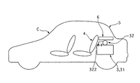
- FIG. 1 is an explanatory diagram of a vehicle battery protection device according to a first embodiment.
- the vehicle battery protection device 1 according to the first embodiment includes a rear parcel board 2 provided in the vehicle C, and protects the battery 3 used for driving the vehicle.
- a battery 3 is provided behind the rear seat 4 of the vehicle C.
- a rear parcel board 2 is provided above the battery 3 and behind the rear seat 4 to partition the interior and exterior of the vehicle up and down.
- a rear windshield 5 is disposed further rearward and upward of the rear parcel board 2, and the rear parcel board 2 is positioned inside the rear windshield 5.
- FIG. 2 is an explanatory diagram of the structure of the rear parcel board according to the first embodiment.
- FIG. 3 is an explanatory diagram of the rear parcel board according to the first embodiment.
- the rear parcel board 2 includes a nonwoven fabric portion 21, a binder 22, a porous ceramic 23, and an opening 24.
- the rear parcel board 2 has a flat plate shape mainly formed from the nonwoven fabric portion 21 and is disposed so as to have a wide surface in the vertical direction.
- the opening part 24 which connects the upper vehicle interior and the downward direction is provided. Air for cooling the battery 3 is sent from the vehicle interior to the battery 3 through the opening 24. Further, a heat reflecting material is added to the rear parcel board 2. As shown in FIG.
- a binder 22 is applied as an adhesive to the nonwoven fabric portion 21, and the porous ceramic 23 is adhered in a large amount over a wide range.
- the porous ceramic 23 is kneaded and supported on the nonwoven fabric fiber of the nonwoven fabric portion 21 via the binder 22.
- another thing is good also as a heat
- FIG. 4 is an explanatory diagram of the battery for the vehicle according to the first embodiment.
- the battery 3 in the first embodiment is a battery used for driving a vehicle, and outputs approximately several hundred volts.
- a case 31 is provided on the outermost periphery of the battery 3, and an electric fan 32 is provided on the case 31.
- the charge / discharge of the battery 3, the capacity, and the electric fan 32 are controlled by the battery controller 33.
- the electric fan 32 of the battery 3 has a cooling structure that cools the battery 3 by taking in the vehicle compartment air from the opening 24 of the rear parcel board 2 through the duct 321 and sending it into the case 31 through the air duct 322. is there.
- FIG. 5 is an explanatory diagram illustrating a usage state of the vehicle battery protection device of the first embodiment.
- the solar radiation 101 inserted from the rear windshield 5 is irradiated to the rear parcel board 2 in this state where the temperature rises most when left in the sun.
- the porous ceramic 23 is bonded (supported) by the binder 22 to the entire surface of the nonwoven fabric portion 21 forming the rear parcel board 2. Therefore, the solar radiation 101 is reflected by the high light reflectivity of the porous ceramic 23 to become reflected light 102 (see FIG. 4). As a result, heat is reflected.
- the temperature of 3 is also suppressed from rising.
- the porous ceramic 23 is also disposed around the opening 24 of the opening 24 through which the electric fan 32 of the battery 3 takes air from the vehicle interior. Therefore, it suppresses that the air which the electric fan 32 takes in from a vehicle interior by the heat rise around the opening part 24 is heated by solar radiation.
- a vehicle battery protection device for protecting the battery 3 installed in the vehicle C to be used for driving which is disposed above the battery 3 and is exposed to solar radiation through the rear windshield 5. Since the reflecting means to which the heat reflecting material for improving the solar radiation reflectivity is provided, the vehicle member on the upper side of the battery 3 is prevented from being warmed by the solar radiation, and consequently the temperature of the parked battery located below the battery rises. The battery life can be extended.
- the reflecting means adds the porous ceramic 23 to the rear parcel board 2 as a heat reflecting agent, it reflects the solar radiation by the high light reflectivity which is a property of the porous ceramic 23. By doing so, it is possible to suppress the rear parcel board 2 from being warmed by solar radiation, and consequently to suppress the temperature rise of the parked battery located below the rear parcel board 2, thereby extending the life of the battery.
- the battery 3 is provided with an electric fan 32 as a cooling means, and the rear parcel board 2 is provided with an opening 24, and the air inside the vehicle compartment is sent from the opening 24 to the electric fan 32.
- the reflecting means has added the porous ceramic 23 at least around the opening 24 of the rear parcel board 2, the air that is taken in by the electric fan 32 and blown to the battery 3 is suppressed from being heated, The temperature rise of the battery during parking can be suppressed, and the battery life can be extended.
- the vehicle member is the rear parcel board 2 that is formed of the nonwoven fabric portion 21 and partitions the interior and exterior of the vehicle behind the rear seat 4, the solar radiation is reflected on the upper portion of the battery 3. And by suppressing that it is warmed, the temperature rise of the parked battery can be suppressed, and the battery life can be extended. Moreover, the rise of the vehicle interior temperature at the time of parking in hot weather can be suppressed.
- a porous ceramic 23 is added to the rear parcel board 2 which is disposed above the battery 3 installed in the vehicle C so as to be used for driving, and is exposed to sunlight through the rear windshield 5, thereby enhancing the reflectivity of solar radiation. Therefore, it is possible to suppress the vehicle member at the upper part of the battery 3 from being warmed by solar radiation, and consequently to suppress the temperature rise of the parked battery positioned below the battery member, thereby extending the life of the battery.
- Example 2 is an example in which a heat reflecting agent is provided by impregnating a rear parcel board formed of nonwoven fabric fibers.
- the configuration will be described.
- a rear parcel board as an intermediate is formed from nonwoven fabric fibers, and the rear parcel board is impregnated by being immersed in a solvent using an aqueous solution of 5 wt% to 30 wt% of porous ceramic.
- the rear parcel board 2 provided with the heat reflecting agent of the porous ceramic is formed.
- An aqueous solution of porous ceramic is less effective at 5 wt% or less, and secondary aggregation occurs at 30 wt% or more, and cost merit cannot be obtained. Since other configurations are the same as those of the first embodiment, description thereof is omitted.
- Example 2 porous ceramic is included in the rear parcel board 2 by impregnation.
- the impregnation is an easy process, and the porous ceramic can be spread over the nonwoven fabric fibers so as to be included in the entire rear parcel board 2, thereby reducing the cost.
- the vehicle battery protection device has the following effects in addition to the above (1) to (4).
- Example 3 is an example in which a heat reflecting agent is provided on the rear parcel board by spray coating.
- the configuration will be described.
- a rear parcel board as an intermediate is formed from nonwoven fabric fibers, and a solvent using an aqueous solution of 5 wt% to 30 wt% of porous ceramic is spray-applied to the rear parcel board.
- the rear parcel board 2 provided with the heat reflecting agent of the porous ceramic is formed.
- An aqueous solution of porous ceramic is less effective at 5 wt% or less, and secondary aggregation occurs at 30 wt% or more, and cost merit cannot be obtained. Since other configurations are the same as those of the first embodiment, description thereof is omitted.
- Example 3 porous ceramic is included in the rear parcel board 2 by spray coating.
- spray coating a large amount of porous ceramic can be added to the surface of the rear parcel board 2 that is exposed to solar radiation. Therefore, the amount of porous ceramic is less than that included in the whole, and the reflection effect can be equivalent. Therefore, cost is suppressed.
- the vehicle battery protection device has the following effects in addition to the above (1) to (4). (10) Since the rear parcel board 2 is formed by applying a porous ceramic solution, the cost can be reduced. (11) In the above (10), since the amount of the porous ceramic is 5 wt% to 30 wt%, the effect of the porous ceramic can be sufficiently obtained and the cost can be sufficiently reduced. Since other functions and effects are the same as those of the first embodiment, description thereof is omitted.
- Example 4 is an example in which the rear parcel board is made of resin.
- FIG. 6 is an explanatory diagram of a vehicle battery protection device according to a fourth embodiment.
- the rear parcel board 6 is made of resin and is manufactured by molding, and a heat reflecting agent is added to the molding material.
- a porous ceramic is used as the heat reflecting agent.
- the addition of the heat reflecting agent is performed by injection molding using a material such as PP, PE, ABS or the like mixed with a base material pellet or previously containing a heat reflecting agent in the pellet.
- the heat reflecting agent is prepared to be 10 to 30 wt%.
- the rear parcel board 6 is obtained which can suppress the cost and can obtain the reflection characteristics uniformly. Since other configurations are the same as those of the first embodiment, description thereof is omitted.
- Example 4 a porous ceramic heat reflecting agent is contained as a pellet in the base material pellet when the rear parcel board 6 is injection-molded. Therefore, the molding process does not increase the number of special processes due to the addition of the heat reflecting agent, and the cost is suppressed. In addition, during injection molding, it is melted and mixed to be integrated, so that very uniform reflectivity can be obtained. Moreover, high carrying property is obtained by forming the resin integrally.
- the vehicle battery protection apparatus has the following effects in addition to the effects (1) to (3).
- the vehicle member is a resin-molded rear parcel board 6 that partitions the interior and exterior of the vehicle behind the rear seat 4, reflecting the solar radiation on the upper part of the battery 3 prevents the vehicle from being warmed.
- the temperature rise of the inside battery can be suppressed, and the battery life can be extended. Moreover, the rise of the vehicle interior temperature at the time of parking in hot weather can be suppressed.
- the rear parcel board 6 is formed by adding a heat-reflecting agent pellet to the base material pellet, and therefore has a high heat-reflecting property without adding a special process to normal forming.
- a rear parcel board 6 can be formed.
- the rear parcel board 6 having uniform heat reflectivity can be formed.
- the opening is provided in the same manner as in the first embodiment, and the effect of suppressing the warming of the air blown to the battery 3 is the same as in the first embodiment. Since other functions and effects are the same as those of the first embodiment, description thereof is omitted.
- Example 5 is an example in which a heat reflecting agent is provided by impregnating a rear parcel board formed by resin molding.
- the configuration will be described.
- a rear parcel board as an intermediate is formed by resin molding, and the rear parcel board is immersed in a solvent using an aqueous solution of 5 wt% to 30 wt% of porous ceramic.
- the rear parcel board 6 provided with the heat reflecting agent of the porous ceramic is formed.
- An aqueous solution of porous ceramic is less effective at 5 wt% or less, and secondary aggregation occurs at 30 wt% or more, and cost merit cannot be obtained. Since other configurations are the same as those of the fourth embodiment, description thereof is omitted.
- Example 5 a porous ceramic is included in the surface layer of the rear parcel board 6 by impregnation.
- the porous ceramic is less than the total amount, and the effect is the same. Therefore, cost is suppressed.
- the vehicle battery protection device of the fifth embodiment has the following effects in addition to the above (1) to (3), (5).
- the porous ceramic solution has an amount of the porous ceramic of 5 wt% to 30 wt%, the effect and cost reduction can be sufficiently obtained. Since other functions and effects are the same as those of the fourth embodiment, description thereof is omitted.
- Example 6 is an example in which a heat reflecting agent is provided on the rear parcel board by spray coating.
- the configuration will be described.
- a rear parcel board as an intermediate is formed by resin molding, and a solvent using an aqueous solution of 5 wt% to 30 wt% of porous ceramic is spray-applied to the rear parcel board.
- the rear parcel board 6 provided with the heat reflecting agent of the porous ceramic is formed.
- An aqueous solution of porous ceramic is less effective at 5 wt% or less, and secondary aggregation occurs at 30 wt% or more, and cost merit cannot be obtained. Since other configurations are the same as those of the fourth embodiment, description thereof is omitted.
- Example 6 porous ceramic is included in the rear parcel board 6 by spray coating.
- spray coating a large amount of porous ceramic can be added to the surface of the rear parcel board 6 that is exposed to solar radiation. Therefore, the amount of porous ceramic is less than that included in the whole, and the reflection effect can be equivalent. Therefore, cost is suppressed.
- the vehicle battery protection device of Embodiment 6 has the following effects in addition to the above (1) to (3), (5).
- the cost can be reduced.
- the amount of the porous ceramic is 5 wt% to 30 wt%, the effect of the porous ceramic solution and the cost reduction can be sufficiently obtained. Since other functions and effects are the same as those of the fourth embodiment, description thereof is omitted.
- Example 7 is an example in which the vehicle member is a tonneau cover. The configuration will be described.
- FIG. 7 is an explanatory diagram of a vehicle battery protection device according to a seventh embodiment.
- Example 7 when a relatively large storage chamber 9 is provided between the rear of the rear seat 4 and the rear windshield 5, the storage object is protected, or the sunshade for the storage object is stored from the outside of the vehicle.
- a heat-reflecting agent is added to the tonneau cover 7 that is provided to prevent the invisible light.
- the tonneau cover 7 is made of a solid resin and includes an internal resin inner layer 71 and a surface resin surface layer 72.
- the resin inner layer 71 of the tonneau cover 7 uses polyvinyl chloride, urethane or the like as a base material.
- the resin surface layer 72 is made of vinyl chloride, urethane or the like as a base material, and 10 to 30 wt% of porous ceramic is mixed and kneaded into the base material.
- the resin surface layer 72 may not be the entire surface as long as it is provided in a region including the upper portion of the battery 3 and the opening. As an example, 50% on the front side of the vehicle is taken as an example. Since other configurations are the same as those of the first embodiment, description thereof is omitted.
- FIG. 8 is an explanatory diagram showing a use state of the vehicle battery protection device of the seventh embodiment.
- Example 7 in the case of a vehicle having a large storage chamber 9 behind the rear seat 4 as shown in FIG. 7, such as a so-called wagon type or van type, the rear windshield 5 and the area equivalent to the rear windshield 5 are used.
- the upper part of the battery 3 is exposed to solar radiation from the rear side windshield 8 having In Example 7, porous ceramic is added to the tonneau cover 7 provided above the storage chamber 9 as a heat reflecting member.
- the solar radiation is reflected above the battery 3 by the high light reflectivity of the porous ceramic, and the heat rise is suppressed. Therefore, the temperature of the battery 3 immediately below the tonneau cover 7 is also suppressed from rising. As a result, deterioration of the battery 3 is prevented, and the battery life is improved. This improvement in battery life makes it difficult for the user to replace the vehicle battery.
- action which suppresses that the accommodation accommodated in the storage chamber 9 is warmed by solar radiation will further improve with a porous ceramic.
- the opening is provided in the same manner as in the first embodiment, and the effect of suppressing the warming of the air blown to the battery 3 is the same as in the first embodiment. However, it is not necessarily connected to the duct of the electric fan.
- the vehicle battery protection device has the following effects in addition to the above (1) to (3).
- the vehicle member is the tonneau cover 7 that covers the upper part of the storage chamber 9 of the vehicle C provided behind the rear seat 4, it suppresses the warming of the solar battery 3 by reflecting the solar radiation. Thus, the temperature rise of the parked battery can be suppressed, and the battery life can be extended. Moreover, it is possible to suppress warming of the vehicle contents.
- the tonneau cover 7 has a surface layer formed by kneading 10 wt% to 30 wt% of porous ceramic in the resin base material. Can be formed. Since other functions and effects are the same as those of the first embodiment, description thereof is omitted.
- Example 8 is an example in which a tonneau cover sheet was impregnated to provide a heat reflecting agent.
- the configuration will be described.
- a sheet of tonneau cover 7 as an intermediate is formed of resin or fiber, and the sheet is impregnated by being immersed in a solvent using an aqueous solution of 5 wt% to 30 wt% of porous ceramic.
- the tonneau cover 7 including the porous ceramic heat reflecting agent is formed.
- An aqueous solution of porous ceramic is less effective at 5 wt% or less, and secondary aggregation occurs at 30 wt% or more, and cost merit cannot be obtained. Since other configurations are the same as those of the first embodiment, description thereof is omitted.
- Example 8 porous ceramics are included in the tonneau cover 7 by impregnation of the sheet.
- the impregnation is an easy process, and the porous ceramic can be spread over the resin or fiber so as to be included in the entire sheet, thereby reducing the cost.
- the vehicle battery protection device of the eighth embodiment has the following effects in addition to the above (1) to (3), (6). (18) Since the tonneau cover 7 is formed by impregnating a porous ceramic solution, the cost can be suppressed. (19) In the above (18), since the amount of the porous ceramic is 5 wt% to 30 wt% in the porous ceramic solution, the effect and cost can be sufficiently obtained. Since other functions and effects are the same as those of the seventh embodiment, description thereof is omitted.
- Example 9 is an example in which the tonneau cover is provided with a heat reflecting agent by spray coating.
- the configuration will be described.
- a sheet of tonneau cover as an intermediate is formed of resin or fiber, and a solvent using an aqueous solution of 5 wt% to 30 wt% of porous ceramic is spray-coated on the sheet.
- the tonneau cover 7 including the porous ceramic heat reflecting agent is formed.
- An aqueous solution of porous ceramic is less effective at 5 wt% or less, and secondary aggregation occurs at 30 wt% or more, and cost merit cannot be obtained. Since other configurations are the same as those of the seventh embodiment, description thereof is omitted.
- porous ceramic is included in the tonneau cover 7 by spray coating.
- spray coating a large amount of porous ceramic can be added to the surface of the rear parcel board 2 that is exposed to solar radiation. Therefore, the amount of porous ceramic is less than that included in the whole, and the reflection effect can be equivalent. Therefore, cost is suppressed.
- the vehicle battery protection device of the ninth embodiment has the following effects in addition to the above (1) to (3), (6). (20) Since the tonneau cover 7 is formed by applying a porous ceramic solution, the cost can be reduced. (21) In the above (20), since the amount of the porous ceramic is 5 wt% to 30 wt% in the porous ceramic solution, the effect and cost can be sufficiently obtained. Since other functions and effects are the same as those of the seventh embodiment, description thereof is omitted.
- porous ceramic is used as the heat reflecting material, but other materials may be used.
- the rear parcel board and the tonneau cover are used in the embodiment, but other members may be used.
- a heat reflecting material is added to the resin rear parcel board 6, the resin portion 62 composed only of the base material is used as the lower surface side portion, and the resin portion 61 in which the base material is mixed with the porous chamber ceramic is provided on the upper surface side.
- a part may be formed integrally by so-called two-color molding. In this way, when the rear parcel board 6 has to be thick, the amount of the porous chamber ceramic can be suppressed, which can contribute to cost reduction.
- FIG. 9 is an explanatory diagram of a state in which the rear sunshade is stored in the vehicle battery protection device of the tenth embodiment.
- FIG. 10 is an explanatory diagram of a state in which the rear sunshade is developed in the vehicle battery protection device of the tenth embodiment.
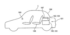
- the vehicle battery protection device 1001 according to the tenth embodiment includes a rear sunshade 1002 provided in the vehicle C, a battery controller 1003, and a sunshade controller 1004.
- the rear sunshade 1002 and the controller 1004 are provided in the vehicle C to reduce solar radiation from the rear of the vehicle.
- the battery controller 1003 performs detection, control, and the like for charging / discharging and management of the battery 1005 installed in the vehicle C for driving. That is, the vehicle battery protection device 1001 according to the tenth embodiment is configured by a vehicle device originally provided for a different purpose also serving as a function.
- the control content is shared by the battery controller 1003.
- the installation structure on the vehicle is as shown in FIGS.
- a battery 1005 is disposed behind the rear seat 1006 and below the rear parcel 1007.
- the battery controller 1003 is provided inside the battery 1005.
- the rear sunshade 1002 is provided at the lower end of the rear windshield 1008.
- the sunshade controller 1004 is provided in the vicinity of the rear sunshade 1002 or at an appropriate position. Alternatively, it is provided integrally with a controller that also functions as another device. For example, BCM.
- FIG. 11 is an explanatory perspective view showing the structure of the rear sunshade of the tenth embodiment.
- the rear sunshade 1002 includes a main body 1021, an opening 1022, a drive unit 1023, a lower arm 1024, an upper arm 1025, a stretching member 1026, a sheet 1027, and a winding unit 1028.
- the main body 1021 is cylindrical and is provided at the lower end of the rear windshield 1008 behind the rear parcel 1007 as shown in FIGS.
- a take-up portion 1028 urged in a direction to take up the sheet 1027 into the main body 1021 by a spring mechanism (not shown) is provided inside the main body 1021. Then, the base end of the sheet 1027 is fixed to the winding unit 1028, and the sheet 1027 is wound up. The sheet 1027 is pulled out from an opening 1022 provided in the main body 1021. The front end of the seat 1027 is stretched in the left-right direction of the vehicle C so that the side is fixed to the stretching member 1026.
- drive units 1023 controlled by the controller 1004 are arranged on the left and right sides of the main body 1021, respectively.
- the drive unit 1023 includes a motor and a speed reduction mechanism.
- One end of the upper arm 1025 is swingably attached to both ends of the spanning member 1026, and one end of the lower arm 1024 is swingably attached to the other end of the left and right upper arms 1025, respectively. Further, the other ends of the left and right lower arms 1024 are respectively attached to the output shafts of the drive unit 1023.
- the stretching member 1026, the upper arm 1025, and the lower arm 1024 are formed by bending the left and right upper arms 1025 and lower arms 1024 toward the center to form a dogleg shape. This is a mechanism structure for moving the machine forward and backward from the main body 1021.
- the sheet 1027 in Example 10 is manufactured by molding, and a heat reflecting agent is added to the molding material.
- a porous ceramic is used as the heat reflecting agent.
- the heat-reflecting agent is added to resin pellets such as PP, PE, ABS, etc. mixed or pre-kneaded with the heat-reflecting agent.
- the content of the heat reflecting agent is adjusted to a ratio of 10 to 30% by weight.
- the content of the heat reflecting agent is 10% by weight or less, a desired heat reflecting effect may not be obtained, and when the content of the heat reflecting agent is 30% by weight or more, the heat reflecting performance due to secondary aggregation. This is because the heat reflection performance corresponding to the high cost cannot be expected, and the material characteristics are also adversely affected.
- seat which suppresses cost and can obtain a reflective characteristic uniformly.
- the range to which the heat reflecting agent is added is the entire surface of the sheet 1027, and the distance from the opening of the drawn portion from the main body 1021 is considered.
- a temperature sensor 1009 is provided in the vehicle interior to detect the vehicle interior temperature. This detected temperature is output to the battery controller 1003.
- the configuration is such that the temperature sensor 9 is provided as the configuration of the air conditioning system, and temperature information is obtained through communication with the controller of the air conditioning system. The details are omitted because the existing system is used. 9 and 10 show examples of arrangement of the temperature sensor 1009. FIG.
- FIG. 12 is a flowchart showing the flow of battery protection processing executed by the battery controller 1003 of the tenth embodiment. Each step will be described below.
- step S1 the air temperature in the passenger compartment is measured. Specifically, a process for obtaining data from a detection result of a sensor for detecting the temperature in the passenger compartment as an air conditioning system, for example, from an air conditioning controller.
- step S2 it is determined whether the temperature in the passenger compartment is equal to or higher than a predetermined temperature set in advance. If the temperature is equal to or higher than the predetermined temperature, the process proceeds to step S3.
- step S3 the remaining high-power battery, that is, the state of charge SOC of the battery 1005 used for driving is measured.
- This process is a function of the original battery controller 1003.
- step S4 it is determined whether or not the remaining high power battery, that is, the state of charge SOC of the battery 1005 used for driving, can operate the rear sunshade 1002. If possible, the process proceeds to step S5. Proceed to
- step S5 a command is output to the controller 1004, and the output is turned on so that the rear sunshade 1002 deploys the seat 1027.
- step S6 it is determined whether or not the temperature in the passenger compartment is equal to or higher than a predetermined temperature set in advance. If the temperature is higher than the predetermined temperature, the process is terminated with the rear sunshade 1002 turned on, and if the temperature is lower than the predetermined temperature, the process proceeds to step S7.
- step S7 a command is output to the controller 1004, and the rear sunshade 1002 outputs OFF so that the seat 1027 is accommodated inside the main body 1021.
- step S8 it is determined whether or not the remaining amount of the low-power battery, that is, the remaining amount of the battery (not shown) used for the vehicle device can be used to operate the rear sunshade 102. If possible, the process proceeds to step S9. If possible, end the process.
- step S9 a command is output to the controller 1004, and the output is turned on so that the rear sunshade 1002 deploys the seat 1027.
- step S10 it is determined whether or not the temperature in the passenger compartment is equal to or higher than a predetermined temperature set in advance. If the temperature is higher than the predetermined temperature, the process is terminated with the rear sunshade 1002 turned on, and if the temperature is lower than the predetermined temperature, the process proceeds to step S11.
- step S11 a command is output to the controller 1004, and the rear sunshade 1002 outputs OFF so that the seat 1027 is accommodated inside the main body 1021.
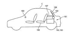
- FIG. 13 is an explanatory diagram illustrating a usage state of the rear sunshade of the vehicle battery according to the tenth embodiment.
- the temperature of the passenger compartment is detected when the engine is stopped or after a predetermined time has elapsed since the engine was stopped (step S1).
- the remaining battery level that is, the state of charge SOC is calculated (step S2).
- the battery controller 1003 controls charging / discharging of the battery 1005 used for driving, the state of charge SOC (%) of the battery 1005, that is, the remaining battery level is obtained by calculation from the obtained detection result (step S3). This is a function originally performed by the battery controller 1003.
- the battery 1005 can supply power from on to off of the rear sunshade 1002, the rear sunshade 1002 is operated to suppress an increase in the temperature of the vehicle interior and the ambient temperature of the battery 1005.
- the temperature rise of the battery 1005 is suppressed (see FIG. 13, steps S4 to S7).
- Example 10 since the porous ceramic is included in the sheet 1027, the solar radiation 101 becomes the reflected light 102 with a high reflectance (see FIG. 13).
- the temperature of the vehicle compartment in the parking lot that is left in the sun is suppressed by the operation of the rear sunshade 1002
- the temperature of the battery 1005 immediately below the rear parcel 1007 is also suppressed from increasing. It will be. This prevents deterioration of the battery 1005 and improves the battery life. This improvement in battery life makes it difficult for the user to replace the vehicle battery.
- the remaining battery level of the battery 1005 is small and not sufficient for the operation of the rear sunshade 1002, the remaining battery level of the existing low-power battery is calculated for the vehicle device, not for driving, and if it can be operated.
- the rear sunshade 1002 is operated by a weak battery. Thereby, the temperature rise of the battery 1005 is more reliably suppressed.
- the following effects can be obtained.
- the controller 1004 and the battery controller 1003 have temperatures detected by the temperature sensor.
- the temperature exceeds a predetermined temperature the rear sunshade 1002 is driven. Therefore, if the vehicle interior temperature is high, the solar radiation is high. In this case, the rear sunshade 1002 is driven to suppress an increase in temperature due to solar radiation.
- the temperature rise of the battery 1005 is suppressed, the temperature rise during parking of the battery can be suppressed, and the battery life can be extended.
- step S3 for calculating the state of charge SOC of the battery 1005 is provided.
- the temperature detected by the temperature sensor is equal to or higher than the predetermined temperature and the remaining battery level is sufficient for operation, Since the rear sunshade 1002 is driven, the remaining amount of the battery is taken into consideration, and the operation can be performed when the operation can be sufficiently performed.
- the sheet 1027 reflects the solar radiation well due to high heat reflectivity, and the temperature rise in the passenger compartment can be well suppressed.
- the sheet 1027 is formed by molding resin pellets kneaded with a heat reflecting agent, a sheet having high heat reflectivity can be formed without adding a special process to normal molding.
- the sheet 1027 has a heat reflecting agent content of 10 to 30% by weight, a sufficient heat reflecting effect can be obtained and the material characteristics can be prevented from being adversely affected.
- the battery 1005 used for driving is provided below the rear windshield 1008 of the vehicle, and the rear sunshade 1002 for unfolding the seat 1027 by driving is provided inside the rear windshield 1008 of the vehicle. Since the seat 1027 is provided with a heat reflecting agent that improves heat reflectivity and suppresses the temperature rise of the battery 1005 due to solar radiation, the temperature rise of the parked battery can be suppressed, and the battery life is extended. be able to.
- Example 11 is an example in which a heat reflecting agent is provided by impregnating a molded sheet.
- the configuration will be described.
- a sheet molded product as an intermediate is formed from a resin, and the sheet molded product is impregnated and dried by immersing it in a solution prepared to have a ratio of 5 to 30% by weight of the porous ceramic. .
- a sheet 1027 provided with a porous ceramic heat reflecting agent is formed.
- the desired heat reflection effect may not be obtained if it is 5% by weight or less, and if it is 30% by weight or more, the heat reflection performance deteriorates due to secondary agglomeration. This is because the reflection performance cannot be expected. Since other configurations are the same as those of the tenth embodiment, description thereof is omitted.
- the vehicle battery protection device of the eleventh embodiment has the following effects in addition to the above (1) to (4), (7).
- (8) Since the sheet 1027 is formed by impregnating and drying a porous ceramic solution, the cost can be suppressed.
- the porous ceramic solution has an amount of the porous ceramic of 5 to 30% by weight, the heat reflection effect and the cost suppressing effect can be sufficiently obtained. Since other functions and effects are the same as those of the tenth embodiment, description thereof is omitted.
- Example 12 is an example in which a heat reflecting agent is provided on the surface layer of the sheet by spray coating.
- the configuration will be described.
- a sheet molded product as an intermediate is formed from a resin, and a solution prepared to have a ratio of 5 to 30% by weight of porous ceramic is spray-coated on the sheet molded product.
- a sheet 1027 provided with a porous ceramic heat reflecting agent is formed.
- the desired heat reflection effect may not be obtained if it is 5% by weight or less, and if it is 30% by weight or more, the heat reflection performance deteriorates due to secondary agglomeration. This is because the reflection performance cannot be expected. Since other configurations are the same as those of the tenth embodiment, description thereof is omitted.
- the vehicle battery protection device of Embodiment 12 has the following effects in addition to the above (1) to (4), (7). (10) Since the sheet 1027 is formed by applying a porous ceramic solution, the cost can be reduced. (11) In the above (10), since the porous ceramic solution has a porous ceramic content of 5 to 30% by weight, a heat reflection effect and a cost suppressing effect can be sufficiently obtained. Since other functions and effects are the same as those of the tenth embodiment, description thereof is omitted.
- the temperature sensor may output the detection result directly to the battery controller.
- a temperature sensor that detects the battery temperature may be used.
- the temperature sensor may be a solar radiation sensor. In that case, the rear sunshade may be controlled based on the intensity of solar radiation as the vehicle interior temperature.
Landscapes
- Engineering & Computer Science (AREA)
- Manufacturing & Machinery (AREA)
- Chemical & Material Sciences (AREA)
- Chemical Kinetics & Catalysis (AREA)
- Electrochemistry (AREA)
- General Chemical & Material Sciences (AREA)
- Mechanical Engineering (AREA)
- Secondary Cells (AREA)
Abstract
L'invention concerne un dispositif de protection de la batterie d'un véhicule un procédé associé, permettant, lorsqu'un véhicule est garé, d'empêcher que n'augmente la température de la batterie du véhicule afin d'augmenter la durée de vie de la batterie. Le dispositif de protection de la batterie du véhicule protège la batterie (3) qui est montée sur le véhicule (C) pour assurer le fonctionnement de celui-ci. Le dispositif comprend une plage arrière (2) placée au-dessus de la batterie (3) et exposée aux rayons du soleil passant à travers le pare-brise arrière (5). La plage arrière (2) comprend des moyens réfléchissants auxquels est ajouté un matériau réfléchissant la chaleur constitué d'un matériau poreux en céramique (23) augmentant la capacité de réflexion des moyens réfléchissants.
Applications Claiming Priority (4)
| Application Number | Priority Date | Filing Date | Title |
|---|---|---|---|
| JP2008023391 | 2008-02-02 | ||
| JP2008-023391 | 2008-02-02 | ||
| JP2008-033939 | 2008-02-15 | ||
| JP2008033939A JP2009190588A (ja) | 2008-02-15 | 2008-02-15 | 車両用バッテリの保護装置及び方法 |
Publications (1)
| Publication Number | Publication Date |
|---|---|
| WO2009096583A1 true WO2009096583A1 (fr) | 2009-08-06 |
Family
ID=40912925
Family Applications (1)
| Application Number | Title | Priority Date | Filing Date |
|---|---|---|---|
| PCT/JP2009/051731 Ceased WO2009096583A1 (fr) | 2008-02-02 | 2009-02-02 | Dispositif de protection de batterie de véhicule et procédé associé |
Country Status (1)
| Country | Link |
|---|---|
| WO (1) | WO2009096583A1 (fr) |
Cited By (2)
| Publication number | Priority date | Publication date | Assignee | Title |
|---|---|---|---|---|
| JP2011042206A (ja) * | 2009-08-20 | 2011-03-03 | Hayashi Telempu Co Ltd | 遮蔽装置 |
| US12485724B2 (en) | 2022-07-26 | 2025-12-02 | Honda Motor Co., Ltd. | System and method for temperature control while charging an electric transport device inside a vehicle |
Citations (8)
| Publication number | Priority date | Publication date | Assignee | Title |
|---|---|---|---|---|
| JP2516113Y2 (ja) * | 1990-07-18 | 1996-11-06 | 三菱自動車工業株式会社 | 排出ガス後処理装置 |
| JP2599677Y2 (ja) * | 1992-02-12 | 1999-09-13 | 日本製箔株式会社 | トランクルーム用トレー |
| JP2003027922A (ja) * | 2001-07-13 | 2003-01-29 | Ibiden Co Ltd | 排気ガス浄化装置 |
| JP2004114900A (ja) * | 2002-09-27 | 2004-04-15 | Denso Corp | 車室内温度上昇抑制装置 |
| WO2006043703A1 (fr) * | 2004-10-19 | 2006-04-27 | Kyoraku Co., Ltd. | Article moule par soufflage a croute superficielle et son procede de fabrication |
| JP2006182208A (ja) * | 2004-12-28 | 2006-07-13 | Kyoraku Co Ltd | 車両用内装パネルおよびその製造方法 |
| WO2007046539A1 (fr) * | 2005-10-21 | 2007-04-26 | Toyota Jidosha Kabushiki Kaisha | Dispositif pour refroidir un dispositif electrique fixe sur un vehicule |
| JP2007161232A (ja) * | 2006-10-24 | 2007-06-28 | Mitsuo Shimoji | 遮蔽装置 |
-
2009
- 2009-02-02 WO PCT/JP2009/051731 patent/WO2009096583A1/fr not_active Ceased
Patent Citations (8)
| Publication number | Priority date | Publication date | Assignee | Title |
|---|---|---|---|---|
| JP2516113Y2 (ja) * | 1990-07-18 | 1996-11-06 | 三菱自動車工業株式会社 | 排出ガス後処理装置 |
| JP2599677Y2 (ja) * | 1992-02-12 | 1999-09-13 | 日本製箔株式会社 | トランクルーム用トレー |
| JP2003027922A (ja) * | 2001-07-13 | 2003-01-29 | Ibiden Co Ltd | 排気ガス浄化装置 |
| JP2004114900A (ja) * | 2002-09-27 | 2004-04-15 | Denso Corp | 車室内温度上昇抑制装置 |
| WO2006043703A1 (fr) * | 2004-10-19 | 2006-04-27 | Kyoraku Co., Ltd. | Article moule par soufflage a croute superficielle et son procede de fabrication |
| JP2006182208A (ja) * | 2004-12-28 | 2006-07-13 | Kyoraku Co Ltd | 車両用内装パネルおよびその製造方法 |
| WO2007046539A1 (fr) * | 2005-10-21 | 2007-04-26 | Toyota Jidosha Kabushiki Kaisha | Dispositif pour refroidir un dispositif electrique fixe sur un vehicule |
| JP2007161232A (ja) * | 2006-10-24 | 2007-06-28 | Mitsuo Shimoji | 遮蔽装置 |
Cited By (2)
| Publication number | Priority date | Publication date | Assignee | Title |
|---|---|---|---|---|
| JP2011042206A (ja) * | 2009-08-20 | 2011-03-03 | Hayashi Telempu Co Ltd | 遮蔽装置 |
| US12485724B2 (en) | 2022-07-26 | 2025-12-02 | Honda Motor Co., Ltd. | System and method for temperature control while charging an electric transport device inside a vehicle |
Similar Documents
| Publication | Publication Date | Title |
|---|---|---|
| US11279210B2 (en) | Roof rack assembly and hood light-blocking fabric assembly that are capable of photovoltaic generation | |
| KR101950025B1 (ko) | 태양광 발전이 가능한 루프랙 조립체 | |
| US10819272B2 (en) | Roof rack assembly and hood light-blocking fabric assembly that are capable of photovoltaic generation | |
| WO2000061397A1 (fr) | Systeme de refroidissement d'habitacle de vehicule | |
| US20040201244A1 (en) | Automobile sunshade | |
| JPH08507987A (ja) | 乗り物用パネルの装置 | |
| WO2007046539A1 (fr) | Dispositif pour refroidir un dispositif electrique fixe sur un vehicule | |
| WO2009096583A1 (fr) | Dispositif de protection de batterie de véhicule et procédé associé | |
| US20100244495A1 (en) | Phase change material usage in window treatments | |
| JP2009190588A (ja) | 車両用バッテリの保護装置及び方法 | |
| CN104875589B (zh) | 树阴化的太阳能车用外置与内嵌结合型防晒装备 | |
| CN208263927U (zh) | 一种智能化远程太阳能辅助空调机构 | |
| CN104626952B (zh) | 一种车载式半自动太阳能充电车衣 | |
| JPS60261725A (ja) | 車内温度自動調整システム | |
| JP2008174085A (ja) | 車両用シートの蓄熱装置 | |
| JPS6132164B2 (fr) | ||
| KR101282696B1 (ko) | 발전형 차양을 갖는 자동차용 복층유리 | |
| JPS609929B2 (ja) | 自動車用換気装置 | |
| JP5061589B2 (ja) | 車両用防曇装置 | |
| CN222291469U (zh) | 一种隔热型汽车防护罩 | |
| US12319119B1 (en) | Solar-powered vehicle interior temperature management system | |
| CN214295537U (zh) | 一种汽车自动防尘罩 | |
| CN110758326A (zh) | 车载除雾玩偶 | |
| KR20040073186A (ko) | 태양열을 이용한 차내 온도 유지장치 | |
| CN2642559Y (zh) | 车辆遮阳防护装置 |
Legal Events
| Date | Code | Title | Description |
|---|---|---|---|
| 121 | Ep: the epo has been informed by wipo that ep was designated in this application |
Ref document number: 09705120 Country of ref document: EP Kind code of ref document: A1 |
|
| NENP | Non-entry into the national phase |
Ref country code: DE |
|
| 122 | Ep: pct application non-entry in european phase |
Ref document number: 09705120 Country of ref document: EP Kind code of ref document: A1 |