WO2009098825A1 - Cuiseur électrique pour riz et procédé de cuisson du riz - Google Patents
Cuiseur électrique pour riz et procédé de cuisson du riz Download PDFInfo
- Publication number
- WO2009098825A1 WO2009098825A1 PCT/JP2008/072933 JP2008072933W WO2009098825A1 WO 2009098825 A1 WO2009098825 A1 WO 2009098825A1 JP 2008072933 W JP2008072933 W JP 2008072933W WO 2009098825 A1 WO2009098825 A1 WO 2009098825A1
- Authority
- WO
- WIPO (PCT)
- Prior art keywords
- rice
- pressure
- pan
- amount
- heating
- Prior art date
- Legal status (The legal status is an assumption and is not a legal conclusion. Google has not performed a legal analysis and makes no representation as to the accuracy of the status listed.)
- Ceased
Links
Images








Classifications
-
- A—HUMAN NECESSITIES
- A47—FURNITURE; DOMESTIC ARTICLES OR APPLIANCES; COFFEE MILLS; SPICE MILLS; SUCTION CLEANERS IN GENERAL
- A47J—KITCHEN EQUIPMENT; COFFEE MILLS; SPICE MILLS; APPARATUS FOR MAKING BEVERAGES
- A47J27/00—Cooking-vessels
- A47J27/08—Pressure-cookers; Lids or locking devices specially adapted therefor
- A47J27/086—Pressure-cookers; Lids or locking devices specially adapted therefor with built-in heating means
-
- A—HUMAN NECESSITIES
- A47—FURNITURE; DOMESTIC ARTICLES OR APPLIANCES; COFFEE MILLS; SPICE MILLS; SUCTION CLEANERS IN GENERAL
- A47J—KITCHEN EQUIPMENT; COFFEE MILLS; SPICE MILLS; APPARATUS FOR MAKING BEVERAGES
- A47J27/00—Cooking-vessels
- A47J27/004—Cooking-vessels with integral electrical heating means
Definitions
- the present invention relates to an electric rice cooker and a rice cooking method, and more particularly, to an electric rice cooker and a rice cooking method in which rice is made by absorbing sufficient water.
- the rice cooker has been devised to increase the water content while preventing starch gelatinization in the water absorption process (see, for example, Patent Documents 1 to 3 below).
- the rice cooker disclosed in the following Patent Document 1 is provided with a steam generating means to increase the water absorption speed.
- This rice cooker supplies steam from the steam generating means to the pot in the water absorption process where the rice absorbs water, that is, the water immersion process, and raises the temperature of the initial rice cooking temperature to a temperature at which gelatinization does not occur.
- the water absorption speed is increased by increasing the rise time of the water temperature.
- the rice cooker disclosed by the following patent document 2 provides a preliminary
- the rice cooker disclosed by the following patent document 3 is provided with the steam treatment process which makes the pressure in a pan higher than atmospheric pressure and absorbs water before a normal water immersion process.
- FIG. 10 is sectional drawing of the rice cooker disclosed by the following patent document 3. As shown in FIG.
- This rice cooker 40 includes a pan 41 for storing rice, a steam generating means 43 for vaporizing water to generate steam, and a pressure adjusting means 44 for adjusting the pressure in the pan 41, and to a normal water immersion process.
- a steam processing step is performed. Specifically, first, rice and a small amount of water for steam generation are put in the pot 41, and the pot 41 is heated by the pot heating means 42 to evaporate the water and generate steam. At this time, the pressure adjusting means 44 closes the steam hole 44a so that steam is not released from the inside of the pan 41, so that the pressure in the pan 41 is increased from the atmospheric pressure. Next, since the internal force in the pan 41 is higher than the atmospheric pressure, the high-temperature steam at 100 ° C.
- an electric rice cooker (hereinafter simply referred to as “rice cooker”) is equipped with a microcomputer, and the microcomputer absorbs a predetermined amount of water into the rice to be cooked in the pan.
- Rice cooking control such as a rising heating process that heats up the cooked rice until it boils, a boiling maintenance process that maintains this cooked rice in a boiling state, a steaming process that steams the cooked rice, and a heat retaining process that keeps the cooked food at a predetermined temperature sequentially. It is supposed to run. And this rice cooking control is performed by determining the amount of rice cooking in the pan.
- a rice cooker disclosed in Patent Document 4 has a temperature range of an initial water temperature divided into a plurality of temperature regions in advance, and a plurality of preset temperature regions are set for each divided temperature region The amount of cooked rice is determined based on a stepped threshold.
- the rice cooker disclosed by the following patent document 5 determines rice cooking amount, raising the detection temperature of an inner pot gradually in a water absorption process, and adjusts subsequent heating amount according to the determination result of rice cooking amount. It is what I did.
- the rice cooker disclosed in the following Patent Document 6 is intermediate when the initial water temperature at the start of rice cooking is higher than a predetermined temperature without using the determination data of the rice cooking amount determination means performed during the water absorption process.
- Patent Document 7 is configured to determine the amount of rice cooked in both the water absorption process and the temperature raising process (corresponding to the above-described rising heating process).
- JP 2003-144308 A paragraphs [0021] to [0023], FIG. 1)
- JP 2005-168546 A paragraphs [0025] to [0033], FIG. 2)
- JP 2007-151648 A paragraphs [0041] to [0046], FIG. 1) Japanese Patent Laying-Open No.
- the rice cooker of the said patent document 2 supplies a vapor
- steam will be rapidly cooled and condensed on the rice surface, and a water droplet will adhere to the rice surface.
- the rice surface will be in the state which is easy to absorb water by the calorie
- steam condenses on the rice surface and water droplets adhere it cannot supply moisture to the starch inside the rice, and it is difficult to increase the moisture content inside the rice. Therefore, it is necessary to allow the rice to absorb water in the subsequent rice cooking process, and as a result, it is difficult to shorten the rice cooking time.
- the rice cooker of the said patent document 3 requires the water supply operation
- open the rice cooker lid feed the water while checking the amount of water corresponding to the amount of rice charged in the pan, and then close the lid and start the normal rice cooking process. It becomes work to let you. This work is troublesome because it cannot be automated and is manual.
- this type of rice cooker heats the pot from the bottom and side walls of the pot, the water and rice adjacent to the bottom and side walls of the pot are heated at a predetermined temperature in the water absorption process. Since the temperature of rice and water is lower than the temperature in the vicinity of the pan bottom and the side wall surface, there is a possibility that the water absorption varies, so-called uneven water absorption.
- the present inventors have been engaged in the development and commercialization of rice cookers for many years, and in recent years, in pressure-type rice cookers that cook rice by increasing the pressure in the pan to atmospheric pressure or higher, the pressure valve in the boiling maintenance step after the water absorption step
- Several patents have already been acquired in the invention (see, for example, Japanese Patent No. 3852293).
- the pressure-type rice cooker disclosed in Japanese Patent No. 3852293 is a boil maintaining step of the rice cooking step, and the pressure valve is forcibly opened to reduce the pressure in the boiling pan to near atmospheric pressure at once. By doing this, a bumping phenomenon is generated in the pan, and the rice grains are controlled to be stirred and cooked.
- this rice cooker heated the inside of the pan in the water absorption process in a state where the pressure valve was opened, that is, in a state where the inside of the pan was not pressurized.
- this water absorption process when the pressure valve was closed and heated at a predetermined temperature to increase the pressure in the pan to a predetermined pressure, it was found that the water content of rice increased. So, in the boiling maintenance process of this pressure rice cooker, the pressure in the pan is increased, so just using this mechanism as it is, just changing the control method of the control device with the existing rice cooker, The present invention has been completed with the idea that the voltage can be increased.
- the present invention has been made in consideration of the above-mentioned development status as well as solving the problems of the above-described conventional technology (background technology 1), and the main object of the present invention is to reduce the moisture content of rice with a simple configuration. It is in providing the electric rice cooker and rice cooking method which can be raised.
- Another object of the present invention is to increase the water content of the rice in the water absorption process by changing the control method without changing the structure of the conventional rice cooker and without newly establishing a new rice cooking process.
- Another object of the present invention is to provide an electric rice cooker and a rice cooking method that can eliminate uneven water absorption and cook delicious rice.
- this rice cooker heated the inside of the pan in the water absorption process in a state where the pressure valve was opened, that is, in a state where the inside of the pan was not pressurized.
- this water absorption process when the pressure valve was closed and heated at a predetermined temperature to increase the pressure in the pan, it was discovered that the water content of rice increased. And this moisture content rises to a high value of a predetermined value, but the pressure to pressurize is saturated at this high moisture content value, and this saturated pressure value is closely related to the amount of cooked rice, that is, this pressure value. It was found that there was a one-to-one relationship with the amount of cooked rice. Therefore, if the pressure in the pan in this water absorption process is detected, the amount of rice cooking can be determined, and the present invention has been completed by conceiving that the problem of determination by temperature can be overcome as in the prior art. Is.
- the present invention has been made in consideration of the above-described development status as well as solving the problems of the above-described conventional technology (background technology 2), and the other object of the present invention is influenced by the environmental temperature in the water absorption process.
- An object is to provide an electric rice cooker and a rice cooking method that can determine the amount of rice cooked.
- Another object of the present invention is to change the control method without changing the structure of the conventional rice cooker and without newly establishing a new rice cooking process, etc., without being affected by the environmental temperature.
- An object is to provide an electric rice cooker and a rice cooking method capable of determining the amount.
- Still another object of the present invention is to provide an electric rice cooker and a rice cooking method capable of increasing the moisture content of rice and achieving the above object.
- an electric rice cooker is a pan in which a cooked rice containing water and rice is accommodated, a heating device that heats the cooked rice in the pan, and
- An electric rice cooker comprising a lid that closes an opening of a pan, and a control device that performs a rice cooking process including a water absorption process for controlling the heating device to absorb water into rice, wherein the control device is In the water absorption step, the pressure in the pan is increased to a predetermined value to cause the rice to absorb water.
- the control device controls the pressure in the pan in a range of 1.05 to 1.18 atm.
- the invention of claim 3 is the electric rice cooker according to claim 1, wherein the pressure in the pan is changed according to the amount of rice cooked in the pan.
- Invention of Claim 4 is an electric rice cooker of Claim 1,
- the pressure detection part which detects the pressure in the said pan, and the detected value of the said pressure detection part are input, and the amount of rice cooking in the said pan is determined.
- the control device includes a storage unit, and the storage unit has a boosted pressure in the pan in the water absorption step and rice cooking amount data corresponding to the pressure.
- the rice cooking amount determination unit determines the amount of rice cooked in the pan by comparing the detected value detected by the pressure detection unit with the rice cooking amount data stored in the storage unit. It is characterized by doing.
- the invention of claim 6 is the electric rice cooker according to claim 4, further comprising a rice cooker body that houses the pan and is provided with the heating device, and the pressure detector converts pressure into an electrical signal.
- a pressure sensor is provided, and the pressure sensor is provided on the lid or the rice cooker body.
- the invention according to claim 7 is the electric rice cooker according to claim 4, wherein in the rice cooking process, a rising heating process in which the cooked food absorbed in the water absorbing process is heated up to a boil, and the cooked rice is cooked.
- a boiling maintenance step for maintaining the product in a boiling state, and the control device is configured so that the first time required for the rising heating step is any amount when the amount of cooked rice in the pan is any amount.
- the heating amount of the heating device is controlled according to the amount of cooked rice in the pan so that the predetermined time is reached and the first time and the second time required for the boiling maintaining step are in a certain relationship. It is characterized by doing.
- the fixed relationship is a relationship in which the first time and the second time are substantially the same.
- the invention according to claim 9 is the electric rice cooker according to claim 1, wherein the lid body has a steam discharge hole for releasing the steam in the pan to the outside, and a valve opening / closing for closing or opening the steam discharge hole.
- the control device operates the heating device in the water absorption step, and closes the vapor discharge hole with the valve opening / closing mechanism to increase the pressure in the pan. To do.
- a tenth aspect of the present invention is the electric rice cooker according to the ninth aspect, wherein the steam discharge hole is also used as a pressure valve, and the valve opening / closing mechanism forcibly opens the pressure valve.
- the control device is configured to control rice cooking by increasing the pressure in the pan to atmospheric pressure or higher.
- An eleventh aspect of the present invention is the electric rice cooker according to the first aspect, wherein the heating device is provided on a bottom heater for heating the bottom of the pan, a side heater for heating the side, and the lid. An upper heater that heats from above; and the control device controls at least a heating amount of the bottom heater in the water absorption step.
- the rice cooking method according to claim 12 is a rice cooking method including a rice cooking step including a water absorption step of storing a predetermined amount of rice to be cooked containing rice and water in a container and causing the rice to absorb water, In the water absorption step, the internal pressure in the container is increased to a predetermined value to cause the rice to absorb water.
- the rice cooking method according to the twelfth aspect in the water absorption step, after the container is sealed, the inside of the container is heated to a predetermined temperature and the pressure in the container at that time is detected. And the amount of rice cooking in the said container is determined based on this detection value, It is characterized by the above-mentioned.
- rice cooking amount data corresponding to the pressure value in the container is set in advance, and the detected pressure value is collated with the rice cooking amount data. The amount of cooked rice is determined.
- the invention of claim 15 is the rice cooking method according to claim 13, wherein in the rice cooking step, the cooked rice absorbed in the water absorbing step is heated up to a boil and heated, and the cooked rice And a boiling maintaining step of maintaining the boiling state, and when the amount of cooked rice in the container is any amount, the first time required for the rising heating step is a predetermined time, and The rice cooking is performed while controlling the amount of heating in accordance with the amount of rice cooked in the pan so that the first time and the second time required for the boiling maintaining step have a certain relationship. .
- the present invention provides the following excellent effects by having the above-described configuration. That is, according to the invention of claim 1, by increasing the pressure in the pan to a predetermined value in the water absorption step, water is efficiently absorbed into the rice and the water content is increased. That is, when the pressure in the pan is increased, pressure is also applied to water and rice, and this pressure makes it easier for water to pass through the rice cell wall, so that more water is absorbed by rice starch. In addition, when a pressure is applied to the rice, a small crack is formed in the rice, water penetrates into the inside of the rice, and water is supplied to the starch in the center of the rice through the gap between the rice cell walls. The rate goes up. Furthermore, there is no variation in water absorption in the pan, so-called uneven water absorption.
- the pressure in the pan is set in the range of 1.05 to 1.18 atm, the rice surface is not gelatinized and water absorption unevenness is not caused. In addition, the rice can absorb sufficient water efficiently and efficiently. This pressure range was confirmed by experiments.
- the amount of cooked rice in the pan can be accurately determined without being affected by the initial water temperature as in the prior art.
- the subsequent rice cooking process for example, the start-up heating process
- the moisture content of the rice is increased by increasing the pressure in the pan, and delicious rice can be cooked by the rice cooking control combined with the above-described accurate rice cooking amount determination result.
- the pressure sensor that converts the pressure into an electric signal, it can be easily attached to the lid or the rice cooker body.
- the relationship between the time required for the start-up heating process and the time required for the boiling maintenance process is also taken into consideration in any rice cooking amount. Cooked rice at the same time. For this reason, the cooking unevenness by the difference in the amount of rice cooking in a pan can be reduced, and it can be set as the same rice cooking in the case of any rice cooking amount.
- the rice cooking process is executed by controlling the heating amount of the heating device so that the time required for the start-up heating process and the time required for the boiling maintenance process are substantially the same.
- the predetermined time required for the start-up heating process to a time during which the appropriate amount of water is absorbed by the rice in the pan in the start-up heating process, A moisture content can be made into a preferable value.
- the steam discharge hole is also used as a pressure valve
- the valve opening / closing mechanism is also used as a pressure valve opening mechanism for forcibly opening the pressure valve. It is possible to cook rice that exhibits the above-described effects in the pressure rice cooker by simply changing the control method without changing the structure of the above and without newly establishing a new rice cooking process.
- the heating device is provided with a bottom heater for heating the bottom of the pan, a side heater for heating the side, and an upper heater provided on the lid and heated from above.
- the control device can increase the pressure in the pan to a predetermined value by controlling at least the heating amount of the bottom heater in the water absorption step. Moreover, if the heating amount of all the heaters is controlled, the pressure in the pan can be increased to a predetermined value more efficiently.
- the invention of claim 12 by increasing the pressure in the container to a predetermined value in the water absorption step, water is efficiently absorbed into the rice and the water content is increased. That is, by pressurizing the inside of the container, pressure is also applied to water and rice, and this pressure makes it easy for water to pass through the rice cell wall, so that more water is absorbed by rice starch.
- a pressure is applied to the rice, a small crack is formed in the rice, water penetrates into the inside of the rice, and water is supplied to the starch in the center of the rice through the gap between the rice cell walls. The rate goes up. Furthermore, there is no variation in water absorption in the container, so-called uneven water absorption.
- the invention of claim 13 is based on the fact that when the pressure in the container is increased in the water absorption process, the moisture content of the rice increases, and the increased pressure value corresponds to the amount of cooked rice. By detecting the increased pressure value, the amount of cooked rice in the container is determined. According to this rice cooking method, the pressure value is not affected by the initial water temperature as in the prior art, so that the determination accuracy can be increased. In this water absorption step, the moisture content of the rice can be increased by increasing the pressure in the container.
- the invention of claim 14 can determine and set an accurate rice cooking amount by previously obtaining and setting rice cooking amount data corresponding to the pressure value by experiment, and collating this rice cooking amount data with the detected pressure value. .
- the invention of claim 15 takes into account the relationship between the time required for the start-up heating process and the time required for the boiling maintenance process, and is the same for any rice cooking amount. I cook rice in time. For this reason, the cooking unevenness by the difference in the amount of rice cooking in a pan can be reduced, and it can be set as the same rice cooking in the case of any rice cooking amount.
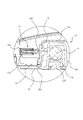
- FIG. 3 is an enlarged view of a portion X in FIG. 2.
- capacitance of a rice cooker is 1.0L (5.5 go cooking) is demonstrated to an example.
- the application range of the present invention is not limited to the rice cooker having this capacity.
- the present invention can be applied to a rice cooker having a capacity of 1.8 L (one-cooked).
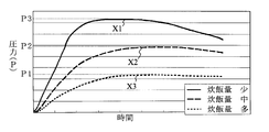
- the relationship between the pressure in the pan and the amount of rice cooked in the water absorption process is substantially constant at a high pressure value P3 that rises steeply from the beginning as shown in the pressure curve X1. And become saturated. Further, when the amount of cooked rice is large, as shown in the pressure curve X3, the rise is dull and the pressure value P1 is low, and the rice is saturated at a substantially constant value. Furthermore, when the amount of cooked rice is an intermediate amount, the pressure curve X2 is located between the pressure curves X1 and X3, and is saturated at a substantially constant value at the intermediate pressure value P2. The amount of rice cooked in each of the pressure curves X1 to X3 is 0.5 cup for the curve X1, 3.3 cup for the curve X2, and 5.5 cup for the curve X3. Yes.
- each pressure value at a stable point of each of the pressure curves X1 to X3 shown in FIG. 7 corresponds to the amount of cooked rice on a one-to-one basis.
- a predetermined amount of rice to be cooked containing rice and water is stored in a predetermined container, for example, a pan, and water is absorbed by the rice. Is increased to a predetermined value, and the amount of cooked rice in the container is determined based on the pressure value at the increased water content.
- rice cooking amount data corresponding to this pressure value is set in advance, and the pressure detection value is compared with the rice cooking amount data to determine the rice cooking amount.
- the container is pressurized by heating the inside with the inside sealed. Therefore, according to this rice cooking method, the pressure value is not affected by the initial water temperature as in the prior art, so that the determination accuracy can be increased.
- the water content of rice can be increased by increasing the pressure in the pot in this water absorption step.
- the heating amount of the heating device can be controlled based on the amount of rice cooking in the subsequent rice cooking step, for example, the start-up heating step, so that the rice cooking characteristics of your choice, such as the hardness of your choice, etc. Can be cooked deliciously.
- the rice cooker 1 includes a pan 10 into which a cooked rice containing rice and water is put, an opening in which the pan 10 is accommodated, and the pan 10 inside.
- a rice cooker main body (hereinafter referred to as a main body) 2 having a bottom heater 5 and a side heater (side heater) 6 for heating and heating the cooked rice, and an opening of the main body 2 pivoted on one side of the main body 2
- a lid body 11 having a lock mechanism 21 that covers and locks in a closed state, a pressure valve 13 that is attached to the lid body 11 to adjust the pressure in the pan 10, and a pressure valve opening that controls the opening and closing of the pressure valve 13
- Heating device and pressure valve opening mechanism 15 And a control unit 9 for controlling.
- the control device 9 is provided with a storage unit.
- the storage unit heats the cooked rice in the pan 10 to a predetermined temperature and absorbs a predetermined amount of water over the predetermined time.
- Process rising heating process for heating and heating the absorbed cooked rice until boiling, boiling maintaining process for maintaining the cooked rice in a boiling state, steaming process for steaming the cooked rice after the boiling maintaining process,
- the rice cooking and the heat retention program which perform sequentially the heat retention process etc. which heat-retained the cooked rice cooked after the steaming process at predetermined temperature are memorize
- the cooking process is executed by increasing the pressure in the pan to atmospheric pressure or higher, for example, about 1.1 to 2.2 atmospheres.
- related the pressure value and the amount of rice cooking are memorize
- the main body 2 is composed of a bottomed box-type outer case 3 and an inner case 4 which is accommodated in the outer case 3 and in which the pot 10 is accommodated, and a gap is formed between the outer case 3 and the inner case 4. And a control circuit board constituting the control device 9 is disposed in the gap.
- the inner case 4 is provided with a bottom heater 5 at the bottom 4a and a side heater 6 at the side 4b.
- As the bottom heater 5 an electromagnetic induction coil wound in a donut shape is used.
- the bottom 4a is provided with a pan bottom temperature sensor 7 composed of a thermistor for detecting the pan bottom temperature.
- the main body 2 is provided with a display panel 8a for displaying various rice cooking menus on the front surface 2a and a display operation unit 8 including operation buttons for selecting the rice cooking menu.
- the pan 10 is composed of a relatively deep bottom container into which a predetermined amount of rice to be cooked made of rice and water is put, and is made of, for example, a clad material of aluminum and stainless steel.
- the lid 11 includes an inner lid 12 that closes the opening of the pan 10, an outer lid 20 that closes the entire opening of the main body 2, and the like.
- One end of the lid 11 is pivotally supported on one end of the main body 2 by a pivot 11 ⁇ / b> A, and the other end is locked to the other end of the main body 2 by a lock mechanism 21.
- the lid 11 is provided with a pressure detector 26 that detects the pressure in the pan 10.
- the pressure detection unit 26 includes a pressure sensor 27 that converts pressure into an electrical signal, and the pressure sensor 27 is provided on the outer lid 20 of the lid body 11.
- the inner lid 12 has a pressure valve 13 at its upper part, a pressure valve opening mechanism 15 for forcibly opening the pressure valve 13, and the pressure in the pot 10 when the pressure in the pot 10 rises to an abnormal pressure of a predetermined value or more.
- a safety valve V1 for releasing steam to the outside, an inner lid heater (also referred to as an upper heater) 19 for heating the inside of the pan 10 from above, and the like are provided.
- the inner lid heater 19 is a heater in which a heating wire similar to the side heater 6 is covered with a heat-resistant member.
- the pressure valve 13 includes a valve seat 13 a in which a valve hole 131 having a predetermined diameter is formed, and a metal mounted on the valve seat 13 a so as to close the valve hole 131.
- the ball 14 is made of a metal and a cover 13b that restricts the movement of the ball 14 and holds it on the valve seat 13a.
- the ball 14 has a predetermined weight and closes the valve hole 131 by its own weight.
- the pressure valve opening mechanism 15 includes a cylinder 15a around which an electromagnetic coil is wound, a plunger 15b that slides in the cylinder 15a by excitation of the electromagnetic coil and moves the ball 14, and the plunger It comprises a spring and an operating rod 15b 'mounted on the tip of 15b.
- the operating rod 15b ' is supported by a sealing member 15c having elasticity.
- FIG. 3 shows a state where the electromagnetic coil is excited.
- the pressure valve opening mechanism 15 is controlled by the control device 9.
- the plunger 15b When the electromagnetic coil is excited based on a command from the control device 9, the plunger 15b is drawn into the cylinder 15a. As a result, the force by which the plunger 15 b pushes the ball 14 in the lateral direction is eliminated, so that the ball 14 is placed on the valve seat 13 a by its own weight, and the valve hole 131 is closed by the ball 14.
- the plunger 15b protrudes from the cylinder 15a by the force of the spring.
- the operating rod 15b 'mounted on the tip of the plunger 15b collides with the ball 14 and pushes the ball 14 in the lateral direction. By this extrusion, the ball 14 is moved from above the valve seat 13a and the valve hole 131 is opened.
- a steam temperature sensor S for measuring the temperature of steam ejected from the valve hole 131 is attached to the upper part of the pressure valve 13.
- the inner lid 12 is fitted with an inner lid packing 18 on the outer periphery thereof so as to be in contact with the opening of the pan 10 and sealed.
- the inner lid packing 18 has a circular hole 18 ⁇ / b> A having a diameter slightly smaller than the diameter of the disk-shaped inner lid 12 and a ring-shaped attachment on the outer peripheral edge of the inner lid 12. It has a mounting portion 18B that is attached via the frame 16, and a seal portion 18C that comes into contact with the opening of the pan 10 and seals the opening, and is composed of a ring having a donut shape as a whole, and has high heat resistance and elasticity. It is formed with the silicon material which has.
- the mounting portion 18B has a concave groove 18B 'in which the ring-shaped mounting frame 16 is mounted, and is formed on the outer periphery of the circular hole 18A.
- the concave groove 18B ' is erected at a substantially right angle upward from an end portion of the groove bottom 18a on the side of the circular hole 18A and a substantially flat annular groove bottom 18a extending outward from the circular hole 18A. It is comprised by the cylindrical wall 18b and extension part 18a 'extended from the groove bottom part 18a.
- the cylindrical wall 18b is formed with a hook-like locking claw 18b 'that protrudes outward from its top and has its tip bent downward.
- the seal portion 18C is further extended from the extended portion 18a 'of the groove bottom portion 18a and is formed in a substantially U shape.
- the U-shaped seal portion 18C is formed by a spring piece portion 18d extending from the extending portion 18a ′ and corresponding to the U-shaped bottom portion, and an elastic seal portion 18e extending from the spring piece portion 18d.
- the elastic seal portion 18e has a tip contact portion 181 that contacts the inner wall 10a of the pan 10, and an intermediate contact portion 182 that contacts the curved portion 10b between the inner wall 10a and the pan flange 10c.
- the mounting frame 16 is fitted into the concave groove 18B ′ and contacted with the surface of the groove bottom 18a, a body 16b extending upward from the bottom 16a, and a flat provided on the body 16b. And a ring frame having a donut shape as a whole, and is formed of a resin molded body having high heat resistance and predetermined mechanical strength.
- the mounting frame 16 is provided with a female screw hole 161 that hangs from the flat surface toward the bottom 16a on the flat surface of the top portion 16c.
- a locking groove 162 is formed on the flat surface of the top portion 16c.
- an H-shaped engaging portion 16b ' having a locking groove 163 is formed on the side surface of the body portion 16b, that is, on the surface side of the cylindrical wall 18b.
- a locking claw 18b ' provided at the top of the cylindrical wall 18b is locked in the locking groove 163 of the H-shaped engaging portion 16b'.
- the ring-shaped attachment frame 16 is attached to the inner lid packing 18.
- the ring-shaped mounting frame 16 is placed on the top of the cylindrical wall 18b of the inner lid packing 18, and the mounting frame 16 is pressed downward.
- the cylindrical wall 18b is bent inward by its elastic force, and insertion of the mounting frame 16 downward is allowed.
- the bottom portion 16a of the mounting frame 16 is pressed to a position where it contacts the bottom surface of the concave groove 18B ', the restoring force of the cylindrical wall 18b returns to the original position, and the top of the cylindrical wall 18b is locked at this timing.
- the claw 18b ′ is locked in the engaging groove 163 of the H-shaped engaging portion 16b ′.
- the inner lid packing 18 is fixed to the mounting frame 16. Thereafter, the mounting frame 16 to which the inner lid packing 18 is fixed is brought into contact with the outer peripheral edge of the inner lid 12, and the male screw 17 is screwed into the female screw hole 161 provided in the outer peripheral edge to be fixed.
- the U-shaped seal portion 18C has a spring piece portion 18d corresponding to the U-shaped bottom portion, and an elastic seal extending from the spring piece portion 18d.
- the elastic sealing portion 18 e of the sealing portion 18 C resists the spring force of the spring piece portion 18 d and the inside of the pot 10. Airtightness is ensured by being in close contact with the wall surface 10a and the curved portion 10b. Therefore, there is almost no steam leakage from the inside of the pan 10, and the loss of heat energy can be suppressed to a minimum, thereby saving energy.
- the inner lid packing 18 is fixed to the inner lid 12 with the attachment frame 16 interposed therebetween, the inner lid packing 18 is supported by the attachment frame 16 having a high mechanical strength. Is firmly fixed. Further, since the mounting frame 16 and the inner lid packing 18 can be mounted and removed without using a tool, the old inner lid packing 18 can be easily replaced.
- the outer lid 20 is formed of a decorative cover that covers the inner lid 12, the pressure valve 13 attached to the inner lid 12, the pressure valve opening mechanism 15, and the like.
- the outer lid 20 is provided with a release button 22 for releasing the lock mechanism 21 of the lid 11 at one end, and a mounting hole 24 at the other end on the pivot 11A side.
- the mounting hole 24 is a bottomed recessed hole having a size that allows the storage cap 25 to be detachably inserted, and is formed in the frame 23 that supports the outer lid 20.
- the mounting hole 24 is formed with a mounting hole 24a into which a discharge cylinder 25a of a to-be-stored cap 25 described later is press-fitted.
- An annular seal member is attached to the mounting hole 24a so as to be in pressure contact with the outer peripheral surface of the discharge cylinder 25a so that the steam in the pan 10 does not leak to the outside.
- the storage cap 25 includes a discharge cylinder 25a that discharges, for example, steam discharged from the pressure valve 13, a vacant chamber 25b that stores a snack of umami components, and a steam discharge port 25c that discharges steam to the outside. It has and the bottom part of the empty room 25b is provided with the toy return valve V2 for returning the stored toy into the pot 10.
- the rice balls that are umami components are led out from the pot 10 through the pressure valve 13 together with the steam and are stored in the empty chamber 25 b of the storage cap 25. Is done.
- the rice balls stored in the empty chamber 25b are opened at a predetermined timing, and the return valve V2 is opened and returned to the pan 10 as the negative pressure valve (not shown) provided in the inner lid 12 is opened.
- the pressure detection unit 26 includes a detection hole (not shown) provided in the inner lid 12 and a pressure sensor 27 provided in correspondence with the detection hole.
- the detection hole and the pressure sensor 27 are included in the pot 10.
- the pressure detection unit is not limited to the above, and may be detected by, for example, the amount of change of the inner lid 12, that is, the amount of change when the inner lid 12 is lifted due to the increase in the pressure in the pan 10, or any other arbitrary It may be possible to detect by this method.
- the control device 9 includes a CPU that performs various arithmetic processes, a storage unit that includes a ROM and a RAM that stores various data, a rice cooking menu detection circuit that detects a selected rice cooking menu, a rice cooking amount determination unit, and an opening / closing of the pressure valve 13.
- a valve opening / closing timer in which time is set, a counter for counting the number of times the pressure valve 13 is opened / closed, a heating control circuit for controlling the heating temperature and heating time in the pan 10, and a display screen displayed on the display panel 8a Display panel control circuit, a pressure valve opening mechanism drive circuit for driving the pressure valve opening mechanism 15 to control the opening / closing timing of the pressure valve 13, and the like.
- rice cooking programs corresponding to various rice cooking menus are stored.
- this rice cooking program is a water absorption process, a start-up heating process, a boiling maintenance process, a steaming process, an additional cooking process, and a heat retaining process after the completion of these rice cooking processes.
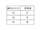
- related the pressure value and the amount of rice cooking are memorize
- this data is large, medium, and small with respect to the pressures P1, P2, and P3.
- the pressure P1 to P3 may be subdivided, and the rice cooking amount may be subdivided corresponding to the pressure. The relationship between this pressure value and the amount of cooked rice has been determined by experiments.
- the controller 9 receives various commands from the menu key 81, the start key 82, the reservation key 83, etc. of the display operation unit 8. Similarly, detection values are input from the pan bottom temperature sensor 7, the steam temperature sensor S, the pressure sensor 27, and the like. In addition, the bottom heater 5, the side heater 6, the inner lid heater 19, the display panel 8a, the pressure valve opening mechanism 15 and the like are connected to this apparatus.
- the control device 9 performs the bottom heater 5 and the side heater according to the selected rice cooking program. 6.
- Control the inner lid heater 19 and the pressure valve opening mechanism 15 to heat the cooked rice in the pan 10 to a predetermined temperature, and absorb a predetermined amount of moisture into the cooked rice over a predetermined temperature and a predetermined time.
- the steaming process IV for steaming is performed.
- the control device 9 closes the pressure valve 13, and controls the heating amount of the bottom heater 5, the side heater 6, and the inner lid heater 19 in this state, and the inside of the pot 10 is set to a predetermined water absorption temperature, For example, at 60 ° C., the rice is allowed to absorb water.
- a predetermined water absorption temperature For example, at 60 ° C., the rice is allowed to absorb water.
- the pressure valve 13 is heated in a closed state, the pressure P in the pan 10 rises along a pressure curve corresponding to the amount of cooked rice, as shown in FIG. It was confirmed that the water content of the rice increased as the pressure in the pan 10 increased. That is, when the moisture content of each part was measured as a bottom A near the bottom of the pot, an intermediate part B higher than the bottom, and an upper part C above the intermediate part in the pot 10 of FIG. As shown in 8A, the bottom A was a1, the middle B was a2, and the upper C was a3, and the average value thereof was aE. This average value was increased by
- the pot 10 is heated to a predetermined temperature and the internal pressure is increased so that the water is absorbed by the rice, so that sufficient water can be effectively and efficiently produced without causing uneven water absorption.
- the rice can absorb water. That is, by raising the pressure in the pot 10, water and rice are also pressurized, and this pressure makes it easier for water to pass through the rice cell wall, so that more water is absorbed by the starch of rice.
- a pressure is applied to the rice, a small crack enters the rice, water penetrates into the rice from there, and water is supplied to the starch in the center of the rice through the gap between the rice cell walls, Increases moisture content.
- This pressure value P is in the range of 1.05 to 1.18 atmospheres, and the rice cooking amount of each pressure curve X1 to X3 is 0.5 cup for curve X1, 3.3 cup for curve X2, and curve X3. Is 5.5 cups, and the amount of cooked rice is small, medium and large in order. Then, when the moisture content of the rice was measured at the time when the pressure value became substantially constant (saturated) in each of the pressure curves X1 to X3, the result of FIG. 8 was obtained, and these contents a1 to a3 were averaged. The measured value aE was increased by 1.0% or more compared to the value aE not boosted. In addition, the relationship between the moisture content and the amount of cooked rice is high when the amount of cooked rice is small, and decreases as the amount of rice is increased. Yes. The relationship between the pressure in the pan 10 and the amount of cooked rice is stored in advance in the storage unit.
- the pressure value P is detected by the pressure sensor 27. This detected value is input to the rice cooking amount determination unit, and compared with the rice cooking amount data stored in the storage unit, the rice cooking amount is determined.
- the pressure value at the stable time point of each of the pressure curves X1 to X3 shown in FIG. 7 has a one-to-one correspondence with the amount of cooked rice.
- the amount of cooked rice is easily and accurately determined. The determination of the amount of cooked rice can be made accurately without being affected by the initial water temperature.
- the heating amount of the heating device is controlled based on the amount of rice cooking.
- the pressure in the pot 10 is increased to, for example, 1.2 atmospheres.
- the accurate rice cooking amount is determined in the water absorption process I, heating is performed with an appropriate amount of electric power from the initial stage of the start-up heating process II based on the accurate rice cooking amount. Therefore, since the temperature rise degree of the start-up heating process II can be freely set by accurately determining the amount of cooked rice, it becomes easy to make a difference in cooking level such as hard and soft. Therefore, it can be cooked deliciously with your favorite rice cooking characteristics, such as your favorite hardness.
- the pressure valve 13 is forcibly opened once or a plurality of times to reduce the pressure in the boiling pot 10 at a stroke so as to be close to the atmospheric pressure.
- the opening of the pressure valve 13 causes a bumping phenomenon in the pan 10, and the rice is vigorously stirred.
- the umami component generated in the pan 10 is temporarily stored in the storage cap 25 through the pressure valve 13.
- the rice balls stored in the storage cap 25 are returned to the pot 10 by opening the return valve V2 at a predetermined timing.
- FIGS. 9A to 9C are referred to as appropriate.
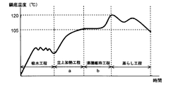
- FIG. 9A to 9C are diagrams showing the relationship between time and temperature (pot bottom temperature) in the rice cooking process.
- FIG. 9A shows a case where the amount of cooked rice is small
- FIG. 9B shows a case where the amount of cooked rice is medium
- FIG. The case where the amount is large is shown.
- the power (starting heating power) applied to the heating device during the start-up heating process II is constant power regardless of the amount of cooked rice, and that the boiling maintaining process III is independent of the amount of rice cooked.
- the electric power (boiling maintenance electric power) given to the heating device is shown as a constant electric power.
- the rising heating power and the boiling maintenance power are different in magnitude.
- the start-up heating process II heating is performed at a constant power regardless of the amount of cooked rice, so as shown in FIGS. 9A to 9C, when the amount of cooked rice is small, the time to reach the boiling state is shortened, and the amount of cooked rice When there is a lot, it takes longer to reach the boiling state.
- Whether or not the boiling state has been reached can be determined based on the temperature measured by the steam temperature sensor S (see FIGS. 3 and 5). For example, the temperature measured by the steam temperature sensor S is 74 ° C. It can be determined that the boiling state has been reached. Further, when the temperature measured by the steam temperature sensor S reaches 74 ° C., the process proceeds from the rising heating process II to the boiling maintaining process III.
- the process proceeds to the boiling maintenance process III before water is sufficiently absorbed by the rice.
- the time required for the boiling maintenance process III becomes long.
- the time b required for the boiling maintenance process III is longer than the time a required for the start-up heating process II (a ⁇ b).
- finish judgment of the boiling maintenance process III is judged by the temperature measured with the pan bottom temperature sensor 7 (refer FIG. 2, FIG. 5).
- the boiling maintenance process III is terminated at that temperature, It is decided to move to the steaming process IV.
- the time a required for the start-up heating process II is the time between when the amount of cooked rice is small and when it is large.
- the average value was about 62.5%, and it did not give a sticky or crusty impression as the state of rice. There was no delicious food and it was ideal.
- the total time required for the start-up heating process II and the boiling maintenance process III be the same in any case of cooked rice .
- the time a required for the start-up heating process II and the time b required for the boiling maintenance process III have a certain relationship (in other words, in any rice cooking amount, It was found that performing the rice cooking step so that the ratio of time a and time b is substantially the same) is preferable in order to eliminate uneven cooking.
- the start-up heating process II in the case of any cooked rice amount, it should be brought to a boiled state rapidly and boiled very slowly It turned out to be unpreferable.
- the preferable time of the start-up heating process II is time when rice can absorb water moderately, and it turned out that this is the same also in any rice cooking amount. In addition, this time is calculated
- the time a required for the start-up heating step which is determined as the time during which water can be appropriately absorbed, and the time b required for the boiling maintenance step III are approximately the same. I understood it.
- a time (predetermined time) for the rice to absorb water appropriately in the start-up heating step II is obtained, and this time is set as the time required for the start-up heating step II.
- this predetermined time is the same time and fixed value in any rice cooking amount.
- the predetermined time obtained previously is the time a required for the start-up heating step II
- the time b required for the boiling maintenance step III is the time a required for the start-up heating step II
- the rice cooking process is performed while controlling the heating amount of the heating device so as to be substantially the same.
- the temperature change pattern as shown in FIG. 9B is an ideal temperature change
- the control device is configured so that the temperature change pattern as shown in FIG. 9 is controlling the heating amount given to the cooked rice in the pan 10 with the heating device (the bottom heater 5, the side heater 6, and the inner lid heater 19). And by this, in the case of any rice cooking amount, it can be made the delicious cooking which has the same taste.
- the moisture content of the cooked rice is about 62.5% on average for any rice cooking amount, and variation in the moisture content of rice in the pan 10 can be suppressed. .
- the control device 9 keeps the inside of the pan 10 at a predetermined time and at a predetermined temperature. In this time zone, the control device 9 intermittently controls on / off of the bottom heater 5, the side heater 6, and the inner lid heater 19 to control the temperature at a predetermined temperature, for example, 70 ° C. or higher.
- a predetermined temperature for example, 70 ° C. or higher.
- the pressure type rice cooker of one Embodiment of this invention was demonstrated, this invention is not limited to this pressure type rice cooker, It can apply also to a normal non-pressure type rice cooker. . Since the non-pressure rice cooker is provided with a steam discharge hole for discharging the steam in the pan to the outside, the above-described effects can be obtained by providing an opening / closing mechanism for opening and closing the steam discharge hole in the steam discharge hole.
- a rice cooker can be configured.
Landscapes
- Engineering & Computer Science (AREA)
- Food Science & Technology (AREA)
- Cookers (AREA)
Abstract
Priority Applications (3)
| Application Number | Priority Date | Filing Date | Title |
|---|---|---|---|
| US12/866,705 US20110003048A1 (en) | 2008-02-07 | 2008-12-17 | Electric rice cooker and method of cooking rice |
| CN2008801262678A CN101938927A (zh) | 2008-02-07 | 2008-12-17 | 电饭煲以及煮饭方法 |
| CA2713015A CA2713015A1 (fr) | 2008-02-07 | 2008-12-17 | Cuiseur electrique pour riz et procede de cuisson du riz |
Applications Claiming Priority (4)
| Application Number | Priority Date | Filing Date | Title |
|---|---|---|---|
| JP2008-027224 | 2008-02-07 | ||
| JP2008027224A JP2009183505A (ja) | 2008-02-07 | 2008-02-07 | 電気炊飯器 |
| JP2008104832A JP2009254451A (ja) | 2008-04-14 | 2008-04-14 | 炊飯量の判定方法及び電気炊飯器 |
| JP2008-104832 | 2008-04-14 |
Publications (1)
| Publication Number | Publication Date |
|---|---|
| WO2009098825A1 true WO2009098825A1 (fr) | 2009-08-13 |
Family
ID=40951908
Family Applications (1)
| Application Number | Title | Priority Date | Filing Date |
|---|---|---|---|
| PCT/JP2008/072933 Ceased WO2009098825A1 (fr) | 2008-02-07 | 2008-12-17 | Cuiseur électrique pour riz et procédé de cuisson du riz |
Country Status (5)
| Country | Link |
|---|---|
| US (1) | US20110003048A1 (fr) |
| KR (1) | KR101213901B1 (fr) |
| CN (1) | CN101938927A (fr) |
| CA (1) | CA2713015A1 (fr) |
| WO (1) | WO2009098825A1 (fr) |
Cited By (5)
| Publication number | Priority date | Publication date | Assignee | Title |
|---|---|---|---|---|
| FR2966711A1 (fr) * | 2010-10-27 | 2012-05-04 | Seb Sa | Procede de commande d'un cuiseur a riz sous pression et cuiseur a riz sous pression pour la mise en œuvre d'un tel procede |
| CN103417103A (zh) * | 2012-05-24 | 2013-12-04 | 林靖权 | 利用辨识功能执行加热的方法及烹饪器具 |
| CN104754992A (zh) * | 2012-10-24 | 2015-07-01 | Seb公司 | 压力电饭锅的控制方法和用于实施该方法的压力电饭锅 |
| CN105581628A (zh) * | 2014-10-24 | 2016-05-18 | 佛山市顺德区美的电热电器制造有限公司 | 电饭煲 |
| CN107801264A (zh) * | 2016-09-01 | 2018-03-13 | 三星电子株式会社 | 烹饪装置及其控制方法 |
Families Citing this family (73)
| Publication number | Priority date | Publication date | Assignee | Title |
|---|---|---|---|---|
| WO2011068078A1 (fr) * | 2009-12-01 | 2011-06-09 | シャープ株式会社 | Cuiseur à riz |
| FR2966712B1 (fr) * | 2010-10-27 | 2012-12-14 | Seb Sa | Procede de commande d'un cuiseur a riz sous pression et cuiseur a riz sous pression pour la mise en oeuvre d'un tel procede |
| US20140044849A1 (en) * | 2011-03-02 | 2014-02-13 | Zeeshan Talat Khan | Apparatus for cooking food |
| CN102293584B (zh) * | 2011-06-14 | 2013-11-27 | 广东洛贝电子科技有限公司 | 一种用于精煮米饭的电压力锅及其控制方法 |
| JP5174218B2 (ja) * | 2011-08-02 | 2013-04-03 | 三菱電機株式会社 | 炊飯器 |
| WO2013061483A1 (fr) * | 2011-10-26 | 2013-05-02 | パナソニック株式会社 | Cuve de cuiseur à riz et cuiseur à riz l'utilisant |
| KR101265106B1 (ko) * | 2012-02-07 | 2013-05-16 | 김차식 | 전기밥솥 |
| JP6213833B2 (ja) * | 2013-02-20 | 2017-10-18 | パナソニックIpマネジメント株式会社 | 圧力式炊飯器 |
| CN103263210B (zh) * | 2013-05-31 | 2016-11-09 | 广东中宝炊具制品有限公司 | 一种多功能汤锅 |
| US10582806B2 (en) * | 2013-11-12 | 2020-03-10 | Henny Penny Corporation | Pressure assist feature for pressure fryer |
| FR3014665B1 (fr) * | 2013-12-13 | 2016-02-05 | Seb Sa | Procede et appareil de chauffage et/ou de cuisson d'aliments a la vapeur |
| US20170099977A1 (en) * | 2014-02-24 | 2017-04-13 | Michelle Yusha Liu | Cooking assembly |
| JP6219229B2 (ja) * | 2014-05-19 | 2017-10-25 | 東京エレクトロン株式会社 | ヒータ給電機構 |
| CN105628564B (zh) * | 2014-10-29 | 2018-02-27 | 珠海格力电器股份有限公司 | 米饭均匀性测试方法、系统及电子设备 |
| CN105607528A (zh) * | 2014-11-21 | 2016-05-25 | 佛山市顺德区美的电热电器制造有限公司 | 电饭煲及其烹饪控制方法 |
| FR3028720B1 (fr) * | 2014-11-25 | 2016-12-02 | Seb Sa | Procede de commande d'un cuiseur a riz et cuiseur a riz pour la mise en œuvre d'un tel procede |
| JP6467629B2 (ja) * | 2015-03-19 | 2019-02-13 | パナソニックIpマネジメント株式会社 | 圧力式炊飯器 |
| EP3289937B1 (fr) * | 2015-04-30 | 2020-02-19 | Stent (Guangzhou) Industrial Co. Ltd. | Cuiseur électrique innovant à double revêtement |
| CN106264176B (zh) * | 2015-06-01 | 2019-02-15 | 佛山市顺德区美的电热电器制造有限公司 | 烹饪器具的加热装置的加热方法 |
| WO2017049635A1 (fr) * | 2015-09-25 | 2017-03-30 | 佛山市顺德区美的电热电器制造有限公司 | Cuiseur électrique |
| KR102018469B1 (ko) * | 2015-11-02 | 2019-09-04 | 미쓰비시덴키 가부시키가이샤 | 가열 조리기 |
| US20170143153A1 (en) * | 2015-11-24 | 2017-05-25 | Illinois Tool Works, Inc. | Multi-functional rf capacitive heating food preparation device |
| CN105768860B (zh) * | 2015-12-23 | 2018-12-04 | 珠海格力电器股份有限公司 | 电压力锅控制方法、装置及电压力锅 |
| CN205458000U (zh) * | 2015-12-25 | 2016-08-17 | 佛山市顺德区爱德实业有限公司 | 一种多功能烹调锅 |
| CA170827S (en) * | 2016-07-22 | 2017-05-03 | Dayou Winia Co Ltd | Electric rice cooker |
| FR3055201B1 (fr) * | 2016-08-30 | 2018-09-07 | Seb S.A. | Procede de commande d’un appareil de cuisson de graines et appareil de cuisson pour la mise en oeuvre d’un tel procede |
| CA170829S (en) * | 2016-09-06 | 2017-05-03 | Dayou Winia Co Ltd | Electric rice cooker |
| CN111938421B (zh) * | 2016-09-30 | 2021-10-26 | 佛山市顺德区美的电热电器制造有限公司 | 电烹饪装置 |
| US11665790B2 (en) * | 2016-12-22 | 2023-05-30 | Whirlpool Corporation | Induction burner element having a plurality of single piece frames |
| CN111728472B (zh) * | 2017-01-05 | 2021-10-29 | 佛山市顺德区美的电热电器制造有限公司 | 电烹饪装置 |
| FR3062559B1 (fr) * | 2017-02-03 | 2021-06-11 | Seb Sa | Procede de cuisson avec modele predictif |
| CN108618563B (zh) * | 2017-03-17 | 2023-11-28 | 佛山市顺德区美的电热电器制造有限公司 | 烹饪器具和烹饪器具的控制方法 |
| CN108720575B (zh) * | 2017-04-17 | 2020-12-22 | 佛山市顺德区美的电热电器制造有限公司 | 烹饪器具的控制方法及烹饪器具 |
| CN108784322B (zh) * | 2017-05-04 | 2020-11-27 | 佛山市顺德区美的电热电器制造有限公司 | 一种控制方法和设备 |
| CN107115011A (zh) * | 2017-05-16 | 2017-09-01 | 宁波华宝食为天电器科技有限公司 | 电压力保温电饭煲双重浸泡煮饭方法 |
| CN108926227B (zh) * | 2017-05-27 | 2021-05-07 | 佛山市顺德区美的电热电器制造有限公司 | 烹饪器具、烹饪倒计时显示方法及装置 |
| KR20190008518A (ko) * | 2017-05-27 | 2019-01-24 | 포샨 순더 메이디 일렉트리컬 히팅 어플라이언시스 메뉴팩쳐링 코., 리미티드 | 전기 밥솥의 제어 방법 및 전기 밥솥 |
| CN108926228B (zh) * | 2017-05-27 | 2021-05-07 | 佛山市顺德区美的电热电器制造有限公司 | 显示烹饪倒计时时间的方法和装置、存储介质及烹饪器具 |
| CN107019414B (zh) * | 2017-06-01 | 2022-10-21 | 杭州向田科技有限公司 | 木桶饭蒸煮设备的烹饪方法 |
| CN109143911B (zh) * | 2017-06-19 | 2022-02-01 | 佛山市顺德区美的电热电器制造有限公司 | 煮饭过程的吸水阶段中控制加热的方法和装置 |
| CN109124331B (zh) * | 2017-06-28 | 2021-09-14 | 松下知识产权经营株式会社 | 煮饭器 |
| CN110123159A (zh) * | 2017-08-09 | 2019-08-16 | 沙克忍者运营有限责任公司 | 烹饪系统 |
| JP6982826B2 (ja) * | 2017-08-30 | 2021-12-17 | パナソニックIpマネジメント株式会社 | 炊飯器および炊飯器の制御方法 |
| CN109419366B (zh) * | 2017-09-01 | 2021-10-15 | 佛山市顺德区美的电热电器制造有限公司 | 烹饪器具中米水量的判断方法和装置、以及烹饪器具 |
| CN109691877A (zh) * | 2017-10-24 | 2019-04-30 | 佛山市顺德区美的电热电器制造有限公司 | 压力锅的煲汤控制方法、压力锅及计算机可读存储介质 |
| CN108851940A (zh) * | 2018-06-13 | 2018-11-23 | 珠海格力电器股份有限公司 | 一种蒸煮器具及其控制方法 |
| USD914436S1 (en) | 2018-06-19 | 2021-03-30 | Sharkninja Operating Llc | Air diffuser with food preparation pot |
| USD883015S1 (en) | 2018-08-09 | 2020-05-05 | Sharkninja Operating Llc | Food preparation device and parts thereof |
| USD883014S1 (en) | 2018-08-09 | 2020-05-05 | Sharkninja Operating Llc | Food preparation device |
| USD934027S1 (en) | 2018-08-09 | 2021-10-26 | Sharkninja Operating Llc | Reversible cooking rack |
| USD903413S1 (en) | 2018-08-09 | 2020-12-01 | Sharkninja Operating Llc | Cooking basket |
| CN110870675B (zh) * | 2018-09-03 | 2021-08-20 | 佛山市顺德区美的电热电器制造有限公司 | 烹饪器具及其加热控制方法 |
| CN110967988A (zh) * | 2018-09-30 | 2020-04-07 | 佛山市顺德区美的电热电器制造有限公司 | 烹饪器具及烹饪器具的控制方法、装置 |
| CN111352362B (zh) * | 2018-12-24 | 2023-12-29 | 佛山市顺德区美的电热电器制造有限公司 | 一种信息处理方法和装置 |
| JPWO2020138459A1 (ja) * | 2018-12-27 | 2021-12-23 | タイガー魔法瓶株式会社 | 調理管理方法、調理管理システム、調理管理サーバ、及び、調理機器 |
| US20190254476A1 (en) | 2019-02-25 | 2019-08-22 | Sharkninja Operating Llc | Cooking device and components thereof |
| CN212788226U (zh) | 2019-02-25 | 2021-03-26 | 沙克忍者运营有限责任公司 | 烹饪系统 |
| CN111685594B (zh) * | 2019-03-12 | 2022-11-29 | 浙江苏泊尔家电制造有限公司 | 烹饪器具和用于烹饪器具的烹饪方法 |
| WO2020187504A1 (fr) * | 2019-03-15 | 2020-09-24 | Koninklijke Philips N.V. | Réduction de sucre dans des produits alimentaires |
| USD982375S1 (en) | 2019-06-06 | 2023-04-04 | Sharkninja Operating Llc | Food preparation device |
| USD918654S1 (en) | 2019-06-06 | 2021-05-11 | Sharkninja Operating Llc | Grill plate |
| DE102019211284A1 (de) * | 2019-07-30 | 2021-02-04 | BSH Hausgeräte GmbH | Küchenmaschine und Verfahren zum Betrieb einer Küchenmaschine |
| CN110507205B (zh) * | 2019-09-30 | 2021-08-20 | 珠海格力电器股份有限公司 | 一种烹饪器具控制方法、装置、存储介质和烹饪器具 |
| CN110989720B (zh) * | 2019-10-30 | 2021-11-16 | 北京万羿科技有限公司 | 一种智能温度控制电饭煲及其控制方法 |
| WO2021127029A1 (fr) * | 2019-12-16 | 2021-06-24 | June Life, Inc. | Accessoire pour appareil de cuisson et procédé d'utilisation |
| CN111166194A (zh) * | 2020-01-13 | 2020-05-19 | 九阳股份有限公司 | 烹饪器具的预约烹饪方法 |
| GB2593468B (en) * | 2020-03-23 | 2022-04-13 | Equip Line Ltd | An apparatus for heating a pot of food or beverage |
| US11647861B2 (en) | 2020-03-30 | 2023-05-16 | Sharkninja Operating Llc | Cooking device and components thereof |
| CN111820719B (zh) * | 2020-07-15 | 2021-10-08 | 九阳股份有限公司 | 基于米量判断的烹饪控制方法 |
| CN112631142A (zh) * | 2020-12-31 | 2021-04-09 | 珠海格力电器股份有限公司 | 一种电饭煲、电饭煲的控制方法及控制装置 |
| USD978600S1 (en) | 2021-06-11 | 2023-02-21 | June Life, Inc. | Cooking vessel |
| USD1007224S1 (en) | 2021-06-11 | 2023-12-12 | June Life, Inc. | Cooking vessel |
| CN113662421B (zh) * | 2021-09-02 | 2022-12-16 | 广东美的厨房电器制造有限公司 | 烹饪器具及其控制方法和控制装置、可读存储介质 |
Citations (1)
| Publication number | Priority date | Publication date | Assignee | Title |
|---|---|---|---|---|
| JPH0622710A (ja) * | 1992-07-09 | 1994-02-01 | Sanyo Electric Co Ltd | 電気炊飯器による炊飯方法 |
Family Cites Families (3)
| Publication number | Priority date | Publication date | Assignee | Title |
|---|---|---|---|---|
| JP3858671B2 (ja) | 2001-11-09 | 2006-12-20 | 松下電器産業株式会社 | 炊飯器 |
| JP4214904B2 (ja) | 2003-12-08 | 2009-01-28 | パナソニック株式会社 | 炊飯器 |
| JP4602938B2 (ja) * | 2006-05-29 | 2010-12-22 | 象印マホービン株式会社 | 圧力炊飯器 |
-
2008
- 2008-12-17 WO PCT/JP2008/072933 patent/WO2009098825A1/fr not_active Ceased
- 2008-12-17 US US12/866,705 patent/US20110003048A1/en not_active Abandoned
- 2008-12-17 CA CA2713015A patent/CA2713015A1/fr not_active Abandoned
- 2008-12-17 KR KR1020107016067A patent/KR101213901B1/ko not_active Expired - Fee Related
- 2008-12-17 CN CN2008801262678A patent/CN101938927A/zh active Pending
Patent Citations (1)
| Publication number | Priority date | Publication date | Assignee | Title |
|---|---|---|---|---|
| JPH0622710A (ja) * | 1992-07-09 | 1994-02-01 | Sanyo Electric Co Ltd | 電気炊飯器による炊飯方法 |
Cited By (8)
| Publication number | Priority date | Publication date | Assignee | Title |
|---|---|---|---|---|
| FR2966711A1 (fr) * | 2010-10-27 | 2012-05-04 | Seb Sa | Procede de commande d'un cuiseur a riz sous pression et cuiseur a riz sous pression pour la mise en œuvre d'un tel procede |
| WO2012056174A3 (fr) * | 2010-10-27 | 2012-08-30 | Seb S.A. | Procede de commande d'un cuiseur a riz sous pression et cuiseur a riz sous pression pour la mise en oeuvre d'un tel procede |
| CN103220947A (zh) * | 2010-10-27 | 2013-07-24 | Seb公司 | 压力电饭锅的控制方法和用于实施该方法的压力电饭锅 |
| CN103417103A (zh) * | 2012-05-24 | 2013-12-04 | 林靖权 | 利用辨识功能执行加热的方法及烹饪器具 |
| CN104754992A (zh) * | 2012-10-24 | 2015-07-01 | Seb公司 | 压力电饭锅的控制方法和用于实施该方法的压力电饭锅 |
| CN105581628A (zh) * | 2014-10-24 | 2016-05-18 | 佛山市顺德区美的电热电器制造有限公司 | 电饭煲 |
| CN105581628B (zh) * | 2014-10-24 | 2018-01-02 | 佛山市顺德区美的电热电器制造有限公司 | 电饭煲 |
| CN107801264A (zh) * | 2016-09-01 | 2018-03-13 | 三星电子株式会社 | 烹饪装置及其控制方法 |
Also Published As
| Publication number | Publication date |
|---|---|
| KR101213901B1 (ko) | 2012-12-20 |
| CN101938927A (zh) | 2011-01-05 |
| US20110003048A1 (en) | 2011-01-06 |
| CA2713015A1 (fr) | 2009-08-13 |
| KR20100105710A (ko) | 2010-09-29 |
Similar Documents
| Publication | Publication Date | Title |
|---|---|---|
| WO2009098825A1 (fr) | Cuiseur électrique pour riz et procédé de cuisson du riz | |
| JP6213833B2 (ja) | 圧力式炊飯器 | |
| CN109965667B (zh) | 烹饪器具的煮饭方法及煮饭系统 | |
| JP2010148801A (ja) | 電気炊飯器及び炊飯方法 | |
| JP2009100887A (ja) | 炊飯器 | |
| JP6213831B2 (ja) | 圧力式炊飯器 | |
| JP2009213607A (ja) | 電気炊飯器 | |
| JP2010004918A (ja) | 炊飯器 | |
| JP2009254451A (ja) | 炊飯量の判定方法及び電気炊飯器 | |
| WO2018154852A1 (fr) | Cuiseur de riz de type à pression | |
| JP5056103B2 (ja) | 炊飯器 | |
| CN109419319B (zh) | 煮饭器以及煮饭器的控制方法 | |
| JP2006325843A (ja) | 圧力調理器 | |
| JP4026620B2 (ja) | 調理器 | |
| JP2011224167A (ja) | 電気炊飯器 | |
| JP2018126267A (ja) | 圧力式炊飯器 | |
| JP2009055937A (ja) | 炊飯器 | |
| JP2011217783A (ja) | 電気炊飯器 | |
| JP5328221B2 (ja) | 炊飯器 | |
| JP2009183505A (ja) | 電気炊飯器 | |
| JP2017035322A (ja) | 炊飯器 | |
| JP2010035911A (ja) | 電気炊飯器 | |
| JP2018134331A (ja) | 圧力式炊飯器 | |
| JP2013111231A (ja) | 圧力式炊飯器 | |
| JP5909630B2 (ja) | 炊飯器および炊飯方法 |
Legal Events
| Date | Code | Title | Description |
|---|---|---|---|
| WWE | Wipo information: entry into national phase |
Ref document number: 200880126267.8 Country of ref document: CN |
|
| 121 | Ep: the epo has been informed by wipo that ep was designated in this application |
Ref document number: 08872151 Country of ref document: EP Kind code of ref document: A1 |
|
| ENP | Entry into the national phase |
Ref document number: 20107016067 Country of ref document: KR Kind code of ref document: A |
|
| WWE | Wipo information: entry into national phase |
Ref document number: 2713015 Country of ref document: CA |
|
| WWE | Wipo information: entry into national phase |
Ref document number: 12866705 Country of ref document: US |
|
| NENP | Non-entry into the national phase |
Ref country code: DE |
|
| 122 | Ep: pct application non-entry in european phase |
Ref document number: 08872151 Country of ref document: EP Kind code of ref document: A1 |