WO2009098871A1 - Procédé de fabrication d'un support d'enregistrement d'information - Google Patents
Procédé de fabrication d'un support d'enregistrement d'information Download PDFInfo
- Publication number
- WO2009098871A1 WO2009098871A1 PCT/JP2009/000428 JP2009000428W WO2009098871A1 WO 2009098871 A1 WO2009098871 A1 WO 2009098871A1 JP 2009000428 W JP2009000428 W JP 2009000428W WO 2009098871 A1 WO2009098871 A1 WO 2009098871A1
- Authority
- WO
- WIPO (PCT)
- Prior art keywords
- resin
- layer
- substrate
- recording medium
- information
- Prior art date
- Legal status (The legal status is an assumption and is not a legal conclusion. Google has not performed a legal analysis and makes no representation as to the accuracy of the status listed.)
- Ceased
Links
Images







Classifications
-
- G—PHYSICS
- G11—INFORMATION STORAGE
- G11B—INFORMATION STORAGE BASED ON RELATIVE MOVEMENT BETWEEN RECORD CARRIER AND TRANSDUCER
- G11B7/00—Recording or reproducing by optical means, e.g. recording using a thermal beam of optical radiation by modifying optical properties or the physical structure, reproducing using an optical beam at lower power by sensing optical properties; Record carriers therefor
- G11B7/24—Record carriers characterised by shape, structure or physical properties, or by the selection of the material
- G11B7/26—Apparatus or processes specially adapted for the manufacture of record carriers
- G11B7/263—Preparing and using a stamper, e.g. pressing or injection molding substrates
-
- G—PHYSICS
- G11—INFORMATION STORAGE
- G11B—INFORMATION STORAGE BASED ON RELATIVE MOVEMENT BETWEEN RECORD CARRIER AND TRANSDUCER
- G11B7/00—Recording or reproducing by optical means, e.g. recording using a thermal beam of optical radiation by modifying optical properties or the physical structure, reproducing using an optical beam at lower power by sensing optical properties; Record carriers therefor
- G11B7/24—Record carriers characterised by shape, structure or physical properties, or by the selection of the material
- G11B7/2403—Layers; Shape, structure or physical properties thereof
- G11B7/24035—Recording layers
- G11B7/24038—Multiple laminated recording layers
Definitions
- the present invention relates to a method for producing an information recording medium for the purpose of reproduction or recording / reproduction formed by laminating a curable resin layer, and particularly to a method for producing an information recording medium having a plurality of information layers.
- optical information recording media capable of recording information at a high density such as CDs and DVDs are widespread.
- Such an optical information recording medium has a transparent substrate, an information layer, and a protective layer.
- the transparent substrate is formed with an information surface composed of concave and convex shapes such as pits representing information signals and guide grooves for tracking recording / reproducing light.
- the information layer is formed of a metal thin film or a thin film material capable of thermal recording laminated on a transparent substrate.
- the protective layer is formed of a resin layer or a transparent substrate that is laminated on the information layer and protects from moisture in the atmosphere. Information is reproduced by irradiating the information layer with a laser beam and detecting a change in the amount of reflected light.
- an information layer is formed by laminating a metal thin film or a thin film material on a resin substrate having a thickness of about 1.1 mm and having an information surface having an uneven shape on one side.
- a protective layer is formed by coating a radiation curable resin typified by an ultraviolet curable resin.
- a CD is produced as described above. Note that the reproduction of the information signal is performed by entering laser light from the substrate side instead of the protective layer side.
- an information layer is formed by laminating a metal thin film or a thin film material on an information surface having a concavo-convex shape on a resin substrate having a thickness of about 0.6 mm, and then a thickness of about 0.6 mm prepared separately. It is manufactured by bonding a resin substrate with an ultraviolet curable resin or the like.
- a Blu-ray disc in which an information layer is formed by laminating a metal thin film or the like on a concavo-convex information surface on a 1.1 mm thick substrate, and a protective layer having a thickness of about 0.1 mm is formed on the information layer.
- a large-capacity medium such as is proposed.
- Blu-ray discs have a narrower information layer track pitch and a smaller pit size than DVDs. Therefore, it is necessary to narrow down the laser spot for recording / reproducing information on the information layer.
- the spot of the laser beam is narrowed down on the information layer by using a dedicated optical head.
- the optical head employs a blue-violet laser with a short wavelength of 405 nm, and an objective lens with a numerical aperture (NA) of 0.85 for narrowing down the laser light.
- NA numerical aperture
- the smaller the spot the more easily affected by the tilt of the disc. If the disc tilts even a little, aberrations occur in the beam spot, resulting in distortion of the focused beam, which makes recording and playback impossible. . Therefore, in the Blu-ray disc, the drawback is compensated by reducing the thickness of the protective layer on the laser incident side of the disc to about 0.1 mm.
- next-generation optical information recording medium having a large capacity such as the Blu-ray disc, as in the case of DVD, it has been proposed to increase the storage capacity by multilayering information layers.
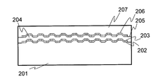
- FIG. 12 shows a cross-sectional view of a two-layer Blu-ray disc having two information layers.
- the two-layer Blu-ray disc has a molded resin substrate 201, a first information layer 203, a resin intermediate layer 204, a second information layer 206, and a protective layer 207.
- the first information layer 203 and the second information layer 206 are made of a metal thin film or a thin film material capable of thermal recording.
- the resin intermediate layer 204 and the protective layer 207 are made of a resin that is substantially transparent to recording / reproducing light.
- a first information surface 202 is formed in a concavo-convex shape on the molded resin substrate 201.
- the first information layer 203 is stacked on the first information surface 202.
- the resin intermediate layer 204 is formed on the first information layer 203.
- On the resin intermediate layer 204 a second information surface 205 having an uneven shape is formed.
- the second information layer 206 is stacked on the second information surface 205.
- the protective layer 207 covers the second information layer 206.
- the term “substantially transparent” means having a transmittance of about 90% or more with respect to recording / reproducing light
- the term “translucent” means 10% or more and 90% or less with respect to recording / reproducing light. It means that it has the transmittance
- This two-layer Blu-ray disc receives a laser beam from the protective layer 207 side and focuses on the information layer to be recorded / reproduced out of the first or second information layer, thereby recording and reproducing signals. It can be performed.
- the thickness of the molded resin substrate 201 is about 1.1 mm
- the thickness of the resin intermediate layer 204 is set to about 25 ⁇ m
- the thickness of the protective layer 207 is set to about 75 ⁇ m.
- Such a multilayer Blu-ray disc manufacturing method is generally performed as follows. As an example, a method for manufacturing a dual-layer Blu-ray disc will be described.
- FIG. 13 shows a manufacturing process of a stamper which is a metal mold for manufacturing a molded resin substrate of an information recording medium.
- a photosensitive material such as a photoresist is coated on a master 301 made of a glass disk or a silicon wafer to produce a photosensitive film 302, and an exposure beam 303 such as a laser beam or an electron beam is used to form a pit or a guide groove.
- the pattern is exposed (FIG. 13A).
- a latent image composed of the exposure unit 304 is formed (FIG. 13B).
- a recording master 306 is obtained in which a concavo-convex pattern 305 is formed on the master 301 with a photosensitive material (FIG. 13C).
- a conductive thin film 307 is formed on the surface of the recording master 306 by using a sputtering method or a vapor deposition method (FIG. 13D).
- a metal plate 308 is formed by metal plating or the like (FIG. 13E).
- the conductive thin film 307 and the metal plate 308 are peeled off at the interface between the photosensitive film 302 and the conductive thin film 307.
- a resin substrate is molded using a metal stamper 309 by a resin molding method such as an injection molding method.
- a resin molding method such as an injection molding method.
- the substrate material a material such as polycarbonate having excellent moldability is often used.
- the resin layer is laminated by using a resin layer forming process using a spin coating method or the like as shown in Patent Document 1.
- FIG. 14 is a diagram showing a manufacturing process of a two-layer disc including a resin intermediate layer and a protective layer manufacturing process using a spin coating method.
- Molded resin substrate 401 is formed by a resin molding method such as an injection molding method using a metal stamper.
- the molded resin substrate 401 has a first information surface formed by pits and guide grooves having a concavo-convex shape on one side, and has a thickness of about 1.1 mm.
- a metal thin film, a thin film material capable of thermal recording, or the like is formed on the first information surface by a sputtering method, an evaporation method, or the like, so that the first information layer 402 is formed.
- the molded resin substrate 401 on which the first information layer 402 is formed is fixed on the rotary stage 403 by a method such as vacuum suction (FIG. 14A).
- the radiation curable resin A404 is applied concentrically on a desired radius by a dispenser (FIG. 14B). Further, by rotating the rotary stage 403, the radiation curable resin A404 is stretched to form the resin layer 406 (FIG. 14C). At this time, the thickness of the resin layer 406 is arbitrarily set to the viscosity of the radiation curable resin A404, the rotation speed of the spin rotation, the rotation time, and the ambient atmosphere (for example, temperature and humidity) in which the spin rotation is performed. Thus, the desired thickness can be controlled. After the spin rotation is stopped, the resin layer 406 is cured by radiation irradiation of the radiation irradiator 405.
- a transfer stamper 407 for forming the second information surface is formed by an injection molding method using a metal stamper as shown in FIG.
- the transfer stamper 407 is fixed on the rotary stage 408 by vacuum suction or the like.
- the radiation curable resin B409 is applied concentrically on a desired radius by a dispenser (FIG. 14 (d)).
- the rotation stage 408 is spin-rotated to stretch the radiation curable resin B409 to form the resin layer 411 (FIG. 14E).
- the thickness of the resin layer 411 can be controlled to a desired thickness as described above. After the spin rotation is stopped, the resin layer 411 is cured by radiation irradiation of the radiation irradiator 410.
- the molded resin substrate 401 on which the resin layers 406 and 411 are formed in this way and the transfer stamper 407 are made of the radiation curable resin C412 on the rotary stage 413 so that the resin layers 406 and 411 face each other.
- the radiation curable resin C is stretched by spin-rotating the rotary stage 413 in an integrated state.
- the radiation layer 415 is irradiated with radiation to cure the resin layer 414 (FIG. 14G).
- the transfer stamper 407 is peeled off at the interface between the transfer stamper 407 and the resin layer 411, whereby the second information is formed on the molded resin substrate 401.
- a surface is formed (FIG. 14 (h)).
- a second information layer 416 is formed by forming a metal thin film, a thin film material capable of thermal recording, or the like on the second information surface by a sputtering method or a vapor deposition method.
- the protective layer 417 is formed by applying and curing the radiation curable resin D by the same spin coating method (FIG. 14 (i)).
- a hard coat layer or the like for preventing defects on the surface of the protective layer due to scratches or adhesion of fingerprints may be formed on the protective layer. In this way, a two-layer Blu-ray disc is completed.
- the radiation curable resin A404 used here is made of a material having good adhesion to the first information layer 402 and the resin layer 414, and the material of the resin layer 411 is the same as that of the transfer stamper 407.
- a material having good releasability and good adhesion to the resin layer 414 is used.
- the radiation curable resins A, B, C, and D are substantially transparent with respect to the wavelength of the recording / reproducing light.
- the production process of the resin intermediate layer using three kinds of radiation curable resins was described here, by controlling the peelability from the radiation curable resin by selecting the material of the transfer stamper, etc., There is also a simpler method in which the type of radiation curable resin is reduced.
- Patent Document 2 a four-layer structure information recording medium having four information recording layers has been proposed.
- each resin intermediate layer needs to have different thicknesses in order to reduce the influence of other layer interference.
- the spin coating method as described above, the viscosity of the radiation curable resin, the rotation speed of the spin rotation, the rotation time, and the ambient atmosphere (for example, temperature and humidity) in which the spin rotation is performed are arbitrarily set. Thus, it is possible to control to a desired thickness. Therefore, conventionally, in order to form resin layers having different thicknesses as in the case of such a four-layer structure information recording medium, it is generally performed by a spin coating method. JP 2002-092969 A JP 2004-213720 A
- the resin intermediate layer is formed by the spin coating method
- the following problems are caused mainly by the fact that the resin is supplied only to a specific region and the centrifugal force used for stretching varies depending on the radial position. Occurs. In other words, it is difficult to form a radiation curable resin layer with a uniform thickness, and the resin reaches the outer peripheral end surface of the molded resin substrate. The resin layer will rise.
- the spin coating method when used, it takes about 10 seconds to apply a single radiation curable resin, which is a factor in reducing the production efficiency in the production of a multilayer information recording medium.
- the resin layer is formed while part of the resin dripped onto the substrate is shaken off. Therefore, a larger amount of resin than the amount of resin actually required for the resin intermediate layer formed on the substrate is used. Need to be dripped. For this reason, the shaken-out resin must be discarded or reused through a new process such as recycling. This is also a factor in reducing productivity.
- a multilayer information recording medium having three or four information layers is manufactured, or when a protective layer is formed, a multilayer coating is performed on the previously formed resin intermediate layer. Therefore, compared with the case where it is applied on the substrate, when it is laminated and applied on the cured resin intermediate layer, the applied resin is less likely to be comparatively spread. In particular, the contact angle in the innermost peripheral region or the outermost peripheral region, which is the end of the coating region, increases, and the resin layer rises significantly.
- An object of the present invention is to produce a plurality of resin layers having different thicknesses without reducing productivity, and to produce a multilayer information recording medium having good signal characteristics.
- a coating method using an ink jet method that enables non-contact coating without requiring a special mask or the like in a desired coating region.
- the method for producing an information recording medium according to the present invention is a method for producing an information recording medium in which a substrate, a plurality of information layers, and a plurality of resin layers having different thicknesses separating the information layers are laminated.
- the resin layer is formed by an inkjet coating method in which a curable resin is discharged onto the substrate while relatively moving either the substrate or the inkjet head. Inkjet coating is performed with a coating pattern in which the amount of resin dropped per unit area on the substrate is different for each region aligned in the radial direction of the substrate.
- the amount of dripping per unit area of resin in the innermost peripheral region and / or outermost peripheral region of the coating region is the amount of dripping per unit area of resin in the adjacent innermost region and / or the adjacent outermost region.
- the ratio of the dripping amount per unit area of the resin in the innermost peripheral region and / or the outermost peripheral region to the dripping amount per unit area of the resin in the adjacent application region may satisfy the following conditions. That is, this ratio is the same as or larger than the resin layer that is applied adjacent to the substrate among the plurality of resin layers relative to the resin layer that is laminated and applied on the resin layer.
- the above-mentioned ratio is preferably changed according to the thickness of the resin layer.
- the dripping amount per unit area of the resin can be varied by using one of the following two methods.
- a method of changing the amount of resin droplets ejected from the inkjet head or a method of changing the coating resolution in the direction of relative movement of the substrate with respect to the inkjet head or in a direction perpendicular to the direction of relative movement is preferable.
- the inkjet head preferably has a structure for discharging a curable resin in accordance with a signal pattern applied to the inkjet head.
- the signal pattern may be a multi-pulse pattern corresponding to one droplet and a pattern in which the multi-pulse pattern is repeated at a constant ejection cycle.
- the droplet amount changing method may be performed by changing the number of pulses of the multi-pulse pattern.
- the droplet amount changing method may be performed by changing the pulse amplitude of the multi-pulse pattern.
- the application resolution changing method may be performed by changing the discharge cycle.
- the inkjet head may have a piezoelectric element, and may have a structure in which a curable resin is discharged according to a signal pattern applied to the piezoelectric element.
- the ink jet head may have a heater and may discharge a curable resin according to a signal pattern applied to the heater.
- the discharge width of the curable resin in the inkjet head may be equal to or greater than the width of the substrate that is perpendicular to the traveling direction of the inkjet head.
- the curable resin may be a radiation curable resin.
- the radiation curable resin may be an ultraviolet curable resin. (The invention's effect)
- the present invention it is possible to form resin layers having different thicknesses by using an inkjet coating method in which a curable resin is discharged onto a substrate while relatively moving either the substrate or the inkjet head. It becomes. Furthermore, since the inkjet coating is performed in a region arranged in the radial direction of the substrate in a coating pattern in which the amount of the resin dropped onto the substrate is different per unit area, the following effects can be obtained. That is, it is possible to eliminate the influence of the bulge at the end of the application region that occurs when a multilayer information recording medium comprising a plurality of information layers is produced, and to realize a resin intermediate layer having a uniform film thickness.
- FIG. 1 is a diagram illustrating a configuration of an inkjet head according to Embodiment 1 of the present invention.
- FIG. 3 is a diagram illustrating a multi-pulse pattern input to the inkjet head according to the first embodiment of the present invention.
- the figure which shows an example of the rising shape of the end surface of the formed resin intermediate
- Sectional drawing which shows an example of the structure of the multilayer information recording medium in Embodiment 2 of this invention.
- the figure which shows the manufacturing process of the conventional stamper.
- the method for producing an information recording medium according to the present invention is a method for producing an information recording medium in which a substrate, a plurality of information layers, and a plurality of resin layers having different thicknesses separating the information layers are laminated.
- the resin layer is formed by an inkjet coating method in which a curable resin is discharged onto the substrate while relatively moving either the substrate or the inkjet head. Inkjet coating is performed with a coating pattern in which the amount of resin dropped per unit area on the substrate is different for each region aligned in the radial direction of the substrate.
- the plurality of application areas are the innermost application area 102, the intermediate application area 103, and the outermost application area 104. .
- the amount of resin dropped per unit area in the innermost coating region 102 and / or outermost region 104 is smaller than the amount of resin dropped per unit area in the intermediate coating region 103.
- the present invention it is possible to form resin layers having different thicknesses by using an inkjet coating method in which a curable resin is discharged onto a substrate while relatively moving either the substrate or the inkjet head. It becomes. Furthermore, since the inkjet coating is performed in a region arranged in the radial direction of the substrate in a coating pattern in which the amount of the resin dropped onto the substrate is different per unit area, the following effects can be obtained. In other words, the effect of the bulging of the innermost peripheral coating region 102 and / or the outermost peripheral region 104 that occurs when a multilayer information recording medium composed of a plurality of information layers is produced, and a resin intermediate layer having a uniform film thickness is realized. it can.
- the ink jet resin discharge method is mainly divided into a piezo method and a thermal method.
- there are various methods for discharging resin but the common thing is that only a low-viscosity liquid can be discharged because of the structure that discharges fine droplets from a small-diameter inkjet nozzle. It is. This does not mean the viscosity of the discharge liquid in the liquid tank at room temperature, but is the resin viscosity around the discharge port of the inkjet nozzle.
- a method in which the vicinity of the discharge port of the inkjet nozzle is heated by a heater or the like to reduce the discharge liquid viscosity and the like may be used.
- the viscosity of the dischargeable discharge liquid in the vicinity of the discharge port is about several mPa ⁇ s to several tens mPa ⁇ s. Therefore, in the production of the resin intermediate layer by the ink jet method, a low-viscosity resin is discharged, and the resin tends to flow after application.
- the inventor of the present invention decided to form resin layers having different thicknesses produced when a multilayer information recording medium was produced by using an ink jet. Furthermore, the inventor of the present invention has realized the present invention by using ink jet for the purpose of eliminating the influence of the bulge at the end of the coated region caused by the multilayer coating.
- FIG. 5 is a sectional view showing a typical configuration example of the ink jet nozzle. Note that the supply path of the discharged discharge liquid, the liquid tank, and the like are omitted from the drawing.
- FIG. 5A shows a type in which a discharge liquid 501 is pushed out by a vibrating element 502 such as a piezoelectric element to perform discharge, and is called a piezoelectric inkjet nozzle.
- FIG. 5B shows a type called a thermal system in which discharge is instantaneously boiled using the heater 503 and discharged using the volume expansion of the discharge liquid 504 in the vicinity of the heater as a power source.
- the three-layer information recording medium includes a molded resin substrate 601, a first information layer 603, a first resin intermediate layer 604, a second information layer 606, a second resin intermediate layer 607, and a third layer.
- An information layer 609 and a protective layer 610 are provided.
- the first information layer 603, the second information layer 606, the second resin intermediate layer 607, and the third information layer 609 are made of a metal thin film or a thin film material capable of thermal recording.
- the first resin intermediate layer 604, the second resin intermediate layer 607, and the protective layer 610 are made of a resin that is substantially transparent to recording / reproducing light.
- the first information surface 602 is formed in a concavo-convex shape on the molded resin substrate 601.
- the first information layer 603 is laminated on the molded resin substrate 601.
- the first resin intermediate layer 604 is formed on the first information layer 603.
- the second information layer 606 is stacked on the second information surface 605.
- the second resin intermediate layer 607 is formed on the second information layer 606.
- a third information surface 608 having an uneven shape is formed on the second information layer 606.
- the protective layer 610 covers the third information layer 609.
- the term “substantially transparent” means having a transmittance of about 90% or more with respect to recording / reproducing light
- the term “translucent” means 10% or more and 90% or less with respect to recording / reproducing light. It means that it has the transmittance
- This three-layer Blu-ray disc receives laser light from the protective layer 610 side and focuses on the information layer for recording / reproducing among the first, second, or third information layer, thereby Recording and playback can be performed.
- the thickness of the molded resin substrate 601 is about 1.1 mm
- the thickness of the first resin intermediate layer 604 and the second resin intermediate layer 607 is about 25 ⁇ m and about 17 ⁇ m, respectively
- the thickness of the protective layer 610 is about 58 ⁇ m. Is set. However, the thickness of the resin intermediate layer and the thickness of the protective layer are not limited to this thickness, and can be arbitrarily set.
- the molded resin substrate 601 is a disc made of polycarbonate or acrylic resin having an outer diameter of 120 mm, a center hole diameter of 15 mm, and a thickness of about 1.0 to 1.1 mm so as to have a shape compatibility with optical disks such as CD and DVD. Formed from.
- an information surface such as a guide groove formed with unevenness on one surface is formed by resin molding by an injection molding method using a metal stamper shown in FIG. In this Embodiment 1, it produces using a polycarbonate.
- the first information layer 603 is required to have at least a characteristic of reflecting reproduction light.
- the first information layer 603 is made of a reflective material containing Al, Ag, Au, Si, SiO2, TiO2, or the like. It is formed using a method such as sputtering or vapor deposition.
- a layer made of a phase change material such as GeSbTe or a recording material such as an organic dye such as phthalocyanine is used. It may contain at least.
- a layer that improves recording / reproducing characteristics such as a reflective layer or an interface layer, may be included as necessary.
- the second information layer 606 and the third information layer 609 can be formed similarly. Recording / reproduction is performed by making recording / reproduction light incident on each information layer from the protective layer 610 side. Therefore, the second information layer 606 and the third information layer 609 are compared with the first information layer 603. The transmittance of the recording / reproducing light with respect to the wavelength is increased.
- the first resin intermediate layer 604 and the second resin intermediate layer 607 are substantially transparent to recording / reproducing light.
- an ultraviolet curable resin mainly composed of acrylic, or an epoxy ultraviolet curable resin.
- a radiation curable resin such as can be used.
- substantially transparent means having a transmittance of 90% or more with respect to the wavelength of the recording / reproducing light, and a material having a transmittance of 95% or more is more preferable.
- middle layer 604 consists of the following two processes. In the first step, a liquid radiation curable resin is applied onto the first information layer 603 using an inkjet application method described later. In the second step, the information surface is transferred to the radiation curable resin using a transfer stamper having an information surface such as a pit or a guide groove. The method for producing the second resin intermediate layer 607 is also the same.
- FIG. 3 is a diagram showing an example of the transfer process of the information surface to the resin intermediate layer in the first embodiment of the present invention.
- a molded resin substrate 701 is transferred into the vacuum chamber 707.
- the molded resin substrate 701 is obtained by completing the application of the radiation curable resin 703 on the first information layer 702.
- the transfer stamper 704 is also disposed in the vacuum chamber 707 (FIG. 3A).
- the transfer stamper 704 is made of a polyolefin material that has a good releasability from the radiation curable resin, and is formed thinner than the molded resin substrate, for example, 0.6 mm. This is because when the transfer stamper is peeled from the molded resin substrate having a thickness of about 1.1 mm, the difference in rigidity due to the difference in the thickness of the substrate is used for the purpose of warping and peeling the transfer stamper.
- the polyolefin material is a material that can easily produce information surfaces such as pits and guide grooves formed with unevenness on one side by a method such as injection molding using a conventional metal stamper as in the case of a molded resin substrate.
- the polyolefin material has a high transmittance to radiation such as ultraviolet rays
- the radiation curable resin can be efficiently cured by irradiating with radiation through a transfer stamper.
- the polyolefin material has a small adhesive force with the cured radiation curable resin, it can be easily peeled off from the interface with the radiation curable resin after curing.
- a center hole for taking eccentricity is provided via a molded resin substrate 701 and a center boss 705.
- the inside of the vacuum chamber 707 is exhausted by a vacuum pump 708 such as a rotary pump or a turbo molecular pump, and a vacuum atmosphere is obtained in a short time.
- a vacuum pump 708 such as a rotary pump or a turbo molecular pump
- a vacuum atmosphere is obtained in a short time.
- the transfer stamper 704 is overlaid on the molded resin substrate 701 (FIG. 3B).
- the pressure plate 706 installed on the upper portion of the transfer stamper 704 pressurizes the transfer stamper 704, and the information surface on the transfer stamper 704 is transferred to the radiation curable resin 703.
- the radiation curable resin 703 and the transfer stamper 704 can be bonded together without air bubbles being mixed therein.
- the molded resin substrate 701 and the transfer stamper 704 bonded together are irradiated with radiation through the transfer stamper 704 by the radiation irradiation device 709 inside or after being taken out of the vacuum chamber 707 (FIG. 3C).
- the transfer stamper 704 is peeled from the interface with the radiation curable resin 703 by driving a wedge between the transfer stamper 704 and the molded resin substrate 701 or blowing compressed air (FIG. 3D).
- the first resin intermediate layer 710 having the information surface transferred thereon is formed.
- the protective layer 610 is substantially transparent to recording / reproducing light, and for example, an ultraviolet curable resin mainly composed of acrylic or a radiation curable resin such as an epoxy ultraviolet curable resin is used. Can do.
- substantially transparent means having a transmittance of 90% or more with respect to the wavelength of the recording / reproducing light, and a material having a transmittance of 95% or more is more preferable.
- a method for forming the protective layer 610 various methods such as a spin coating method, a screen printing method, a gravure printing method, and an ink jet method can be considered.
- the method for forming the protective layer it is most preferable if the same method as that for the resin intermediate layer can be used.
- the ink jet method is also the most preferable method for forming the protective layer.
- the protective layer is formed not only by application of a radiation curable resin, but also by, for example, bonding a sheet-like material made of polycarbonate resin, acrylic resin or the like via an adhesive or the like. Also good.
- the multilayer information recording medium in Embodiment 1 of the present invention uses a blue-violet laser with a laser beam of 405 nm and uses a objective lens with an NA of 0.85 to narrow down the beam from the protective layer 610 side to each information layer for recording. Perform playback.
- the thickness from the surface of the protective layer 610 to the first information layer 603 is set to about 0.1 mm.
- the design value of the thickness of the resin intermediate layer is an example, and the effect of the present invention is not changed even when another thickness design value is used.
- the configuration of the multilayer information recording medium and the outline of the manufacturing method in Embodiment 1 of the present invention have been briefly described.
- the method for producing a multilayer information recording medium of the present invention is characterized by the method for forming the resin intermediate layer, and therefore the scope of the present invention is not limited by the other configuration or the method for producing the same.
- Embodiment 1 of the present invention will be described in detail mainly focusing on the manufacturing method of the resin intermediate layer.
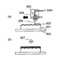
- FIG. 4 is a diagram illustrating an example of a radiation curable resin coating process using the inkjet coating apparatus according to Embodiment 1 of the present invention.
- a molded resin substrate 801 having a first information layer 802 formed on one side is fixed to a stage 803 by vacuum suction or the like.
- An inkjet head unit 804 is disposed above the molded resin substrate 801. The stage 803 and the inkjet head unit 804 can move relatively.
- the inkjet head unit 804 is fixed and the stage 803 is moved in parallel to perform coating.
- the stage 803 and the inkjet head unit 804 may be moved relative to each other.
- the stage 803 may be fixed and the inkjet head unit 804 may be moved in parallel, or both may be moved.
- the fine droplets 806 of the radiation curable resin A are dropped on the molded resin substrate 801 from the inkjet head 805 while the inkjet head unit 804 is moved relatively parallel to the stage 803.
- the ink jet head 805 is provided with a heater, and the resin in the ink jet head 805 can be heated to reduce the viscosity of the resin.
- the stage 803 After applying the fine droplets 806 of the radiation curable resin A to the application region on the molded resin substrate 801, the stage 803 is moved under the radiation curable resin 807, irradiated with radiation, and the applied radiation curable resin is applied. Is cured (FIG. 4B).
- an ultraviolet lamp was used as the radiation irradiation means.
- the ultraviolet lamp there are various lamps such as a metal halide lamp, a high-pressure mercury lamp, and a xenon lamp.
- a xenon lamp is used.
- the region irradiated with radiation may be completely cured, and if it is cured to a state that does not completely cure, the resin flow can be suppressed.
- the state according to the complete curing referred to here means a state in which the viscosity becomes a gel or 10000 mPa ⁇ s or more.
- this coating process is a protective layer production process, the information layer transfer process is not required, and the radiation curable resin layer applied last is also completely cured.
- the inkjet head 805 is provided with at least one inkjet nozzle. Generally, it is used for a printing machine for printing or drawing.
- the ink jet nozzle can eject fine droplets of ink whose main component is pigment or dye.
- Inkjet technology is being developed in the direction of producing droplets as small as possible, for example, droplets of about several pL, and dropping them with high accuracy to achieve higher resolution printing.
- an inkjet nozzle that can eject a large droplet of about several tens of pL.
- Currently available inkjet nozzles for printing presses have a microdroplet volume of about 5 to 50 pL, a compatible resin viscosity that can be discharged is about 5 to 20 mPa ⁇ s around the discharge section, and an operating frequency of 1 kHz to 20 kHz. There are some things.
- an ink jet head using one ink jet nozzle is also conceivable, but it is relatively easy to provide a plurality of ink jet nozzles.
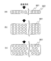
- the inkjet nozzles 901 are arranged in a line perpendicular to the scanning direction of the inkjet head 902, and a head array is provided.
- FIG. There is a configuration in which multiple rows are arranged in the direction.
- FIG. 6C there is a configuration in which a plurality of rows are arranged while the positions of the inkjet nozzles 901 are gradually shifted.
- the configuration of the nozzles in this ink jet head can be represented by an index called nozzle resolution.
- the nozzle resolution means the number of nozzles provided per unit length.
- the number of nozzles per inch can be represented by a unit npi (nozzle per inch).
- an inkjet head having a nozzle resolution of 600 npi is used as the inkjet head 805.
- the resin was ejected using a piezo method in which a piezoelectric element was used and the resin was extruded in accordance with a signal pattern input to the piezoelectric element.
- the configuration of the ink jet head is not limited to the piezoelectric method used in the first embodiment, and the effect of the invention of the first embodiment is not changed even in a head using the thermal method.
- Embodiment 1 of the present invention it is preferable that a length of 120 mm, which is the diameter of the molded resin substrate 801, which is an application target, can be applied at a time. Therefore, it is conceivable to arrange the nozzles in a straight line with a width of 120 mm or more in a direction perpendicular to the scanning direction of the inkjet head.
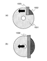
- the discharge width is larger than the length of the application target in the direction perpendicular to the traveling direction of the inkjet head (here, the diameter of the molded resin substrate 1001 that is the application target is 120 mm). It is also possible to apply with a narrow inkjet head unit 1003.
- application is started from a specific portion 1002 of the molded resin substrate 1001.
- the application area cannot be applied by a single run of the inkjet head.
- the inkjet head is shifted by the width of the inkjet head and applied on the substrate by scanning several times, the following problems occur. Each joint in the applied application area has a thickness distribution, or splashes of resin applied later are scattered in the previously applied application area.
- the inkjet head unit 1004 is preferably configured to be longer than the diameter of the molded resin substrate 1001.
- an inkjet nozzle row in which 1000 inkjet nozzles 1101 are linearly arranged at a pitch of 141 ⁇ m in a direction perpendicular to the scanning direction is shifted by 42.3 ⁇ m and arranged in 3 rows.
- an inkjet head 1102 provided with 3000 nozzles in an inkjet head length of 127 mm is used. This ink jet head configuration corresponds to a nozzle resolution of 600 npi. It is possible to selectively control resin discharge for each of the inkjet nozzles.
- the resin When the resin is discharged using all the nozzles, the resin can be dropped with a resolution of 600 dpi (dot per inch). For example, when the resin is dropped using only 1000 nozzles arranged in a row, the resin is dropped at a resolution of 200 dpi.
- dpi dot per inch
- the resin is dropped at a resolution of 200 dpi.
- This is a method of changing the coating resolution in a direction perpendicular to the relative movement direction of the substrate with respect to the inkjet head, and is one of the coating resolution changing methods.
- a signal pattern consisting of a multi-pulse pattern as shown in FIG. 9A is input to the inkjet head to push the resin from the inkjet nozzle and drop the resin onto the substrate. ing.
- the resin is efficiently used by utilizing the mechanical resonance generated when a force is applied to the ink jet nozzle filled with resin from the nozzle by a piezoelectric element provided on the head or a heater. It is for discharging from an inkjet nozzle.
- a multi-pulse pattern composed of four pulses shown in FIG. 9A is set to a pulse period having a frequency close to mechanical resonance in the vicinity of an inkjet nozzle filled with resin.
- the four resin droplets ejected in response to one pulse each are ejected from the nozzle hole, and then combined in the air until reaching the substrate, and are dropped onto the substrate as one droplet. . Therefore, if the amplitude of this multi-pulse pattern is changed, the amount of resin droplets pushed out from the nozzle by the pulse changes, and the number of resin droplets is changed by changing the number of pulses from four to five. It is dropped by 1.25 times. In this way, by changing the amplitude of the multi-pulse pattern or arbitrarily setting the number of pulses constituting the multi-pulse pattern, it is possible to change the amount of one resin droplet ejected from the inkjet nozzle. This functions as a droplet amount changing method for changing the amount of resin dripped onto the substrate.
- the ink jet nozzle is a resin having a viscosity of about 5 to 20 mPa ⁇ s, the resin can be stably discharged to about 15 pL per drop.
- the resin when the resin is dropped on the substrate, the resin is dropped by continuously dropping the resin on the substrate while relatively moving the substrate or the inkjet head.
- the coating resolution in the direction of relative movement of the substrate with respect to the ink jet head is determined by the relative movement speed of the substrate with respect to the ink jet head and the dropping timing of the resin discharged from the ink jet head.
- the dropping timing of the resin discharged from the inkjet head is adjusted by repeating the multi-pulse pattern described above at a constant discharge cycle. By arbitrarily setting the discharge period, the application resolution in the relative movement direction of the substrate with respect to the ink jet head can be changed.
- Example 1 will be described below.
- the coating region is divided into a plurality of regions, the amount of resin dripping per unit area of each coating region is changed, and the swell of the coating end surface shown in FIG. 10 can be eliminated. It is the experiment which examined this, and its result.
- the plurality of application areas are the innermost application area 102, the intermediate application area 103, and the outermost application area 104.
- a three-layer information recording medium as shown in FIG. 2 was produced.
- a special mask for limiting the coating region is not required, and the resin can be dripped in an arbitrary region with an arbitrary dropping amount per unit area.
- Example 1 when the first resin intermediate layer 604 of FIG. 2 is applied, the amount of resin dripping is changed in a region concentrically divided with the center of the substrate 101 as a reference as shown in FIG. Application was performed.
- the application region is divided into three regions concentrically divided with respect to the center of the substrate 101 (the innermost application region 102, the intermediate application region 103, and the outermost application region 104), and each region has a unit.
- Application was performed while changing the amount of dripping per area.
- the resin used was an ultraviolet curable acrylic resin having a viscosity of about 10 mPa ⁇ s at a temperature of 25 ° C.
- the first resin intermediate layer 604 (thickness 25 ⁇ m) shown in FIG. 2 was formed.
- the first resin intermediate layer is formed on the first information layer formed on the substrate.
- the first information layer is not formed on the entire surface from the innermost diameter to the outermost diameter with respect to the substrate, but the substrate surface is exposed near the inner diameter or near the outer diameter of the substrate.
- the first resin intermediate layer is formed so as to cover the information layer. Therefore, the radiation curable resin is in contact with the substrate surface at the innermost peripheral portion or the outermost peripheral portion of the resin application region.
- a first information layer 1302 is formed on a substrate 1301.
- the resin layer 1303 completely covers the first information layer 1302 and further covers the exposed outer peripheral edge of the substrate 1301.
- the outer peripheral end portion of the resin layer 1303 rises as compared with the flat portion inside the resin layer 1303 and becomes lower as it goes further to the outer peripheral side.
- the innermost coating region 102 is a region having a diameter of 22 mm to 24 mm
- the intermediate coating region 103 is a region having a diameter of 24 mm to 117 mm
- the outermost coating region 104 is a diameter of 117 mm to 119 mm. Up to the area.
- the thickness of the first resin intermediate layer 604 was measured as follows. That is, the laser beam having a wavelength of 405 nm is used as a light source to focus the beam on the lens and the information layer formed on the surface of the resin intermediate layer or the molded resin substrate while moving the lens by the actuator. And the thickness was evaluated using the thickness measuring device from the drive amount of the actuator.
- Table 1 shows the results of measurement of the amount of resin dripping per unit area in each region and the rising state of the coating end face.
- Condition numbers 4 and 5 are examples according to the present invention, and condition numbers 1 to 3 and 6 to 8 are comparative examples.
- the inkjet head was fixed, and the substrate was applied while moving the substrate at a constant speed of 120 mm / s.
- the application resolution in the direction perpendicular to the relative movement direction of the inkjet head and the substrate was 600 dpi, and the amount of resin dripping per unit area was changed by changing the application resolution in the relative movement direction of the inkjet head and the substrate.
- the application resolution was changed by changing the ejection cycle of the multi-pulse pattern.
- the resin was irradiated with ultraviolet rays using a radiation irradiation apparatus (here, a xenon UV lamp was used) to perform semi-curing.
- a radiation irradiation apparatus here, a xenon UV lamp was used
- Evaluation of the rise of the end face was performed as follows. With respect to the average thickness of the information recording medium having a diameter of 120 mm around the radius of 40 mm, the inner peripheral end surface is different from the maximum thickness or minimum value of the radius of 12 mm, and the outer peripheral end surface is the thickness maximum value or minimum value of the radius of 58 mm A thickness difference was determined, and a thickness difference of ⁇ 1 ⁇ m was used as a criterion for acceptance.
- the application resolution in the relative movement direction of the inkjet head and the substrate was set to 3000 dpi by setting the discharge cycle to 70.6 ⁇ s.
- the ejection cycle of the innermost peripheral application region 102 and the outermost peripheral application region 104 was changed to 235.2 ⁇ s, and the application resolution was changed to 900 dpi.
- the drop amount ratio between the innermost peripheral application region 102 and the intermediate application region 103 adjacent thereto, and the drop amount ratio between the outermost peripheral application region 104 and the intermediate application region 103 adjacent thereto are 0.
- the thickness difference was within ⁇ 1 ⁇ m with respect to the average thickness around the radius of 40 mm.
- the rising shape of the coating end face can be reduced by reducing the amount of dripping per unit area of the innermost peripheral region and the outermost peripheral region with respect to the coating region adjacent thereto.
- the drop amount per unit area is changed by changing the discharge cycle.
- the method for changing the drop amount is not limited thereto.
- the drop amount may be reduced by changing the signal amplitude of the multi-pulse pattern input to the inkjet head while the ejection cycle is kept constant, or the number of pulses of the multi-pulse pattern may be changed.
- a piezo-type head that extrudes resin with a piezoelectric element is used as an inkjet head, but a thermal-type head that extrudes resin with a heater may be used.
- the second resin intermediate layer is subjected to the information surface transfer step and the second information layer 606 formation step. 607 was formed.
- the formation of the second resin intermediate layer 607 was also evaluated for the raised shape on the coating end surface under the same conditions as the formation of the first resin intermediate layer 604.
- the condition was that the amount of dripping per unit area was changed in three regions concentrically divided into the innermost coating region 102, the intermediate coating region 103, and the outermost coating region 104.
- the drop amount ratio between the innermost application region 102 and the intermediate application region 103 that is the adjacent region, and the drop amount ratio between the outermost application region 104 and the intermediate application region 103 that is the adjacent region are 0. Good results were obtained in the vicinity of 4 to 0.6. More specifically, in Condition No. 4 (Ratio 0.6) and Condition No. 5 (Ratio 0.4), the thickness difference was within ⁇ 1 ⁇ m with respect to the average thickness around a radius of 40 mm. Thus, it has been found that the rising shape of the coating end face can be reduced by reducing the amount of dripping per unit area of the innermost peripheral region and the outermost peripheral region with respect to the coating region adjacent thereto. .
- the thickness criterion is satisfied in the second resin intermediate layer 607 under the condition that the drop amount ratio is small as compared with the result of Table 1 in which the first resin intermediate layer 604 was formed.
- condition number 3 (ratio 0.7) in Table 2 was not preferable although the ratio was the same as condition number 4 (ratio 0.7) in Table 1 is as follows. is there. Since the first resin intermediate layer 604 is applied on the molded resin substrate 601, it is difficult for the bulge to increase, whereas the second resin intermediate layer 607 is applied on the first resin intermediate layer 604. As a result, the excitement tends to increase. Therefore, in the first resin intermediate layer 604, it is necessary to increase the drop amount ratio between the intermediate application region 103, the innermost peripheral application region 102, and the outermost peripheral application region 104. On the other hand, in the second resin intermediate layer 607, when the drop amount ratio between the intermediate application region 103, the innermost peripheral application region 102, and the outermost peripheral application region 104 is increased, the swell is excessively increased.
- the ratio of the dropping amount per unit area of the plurality of resin layers of the resin intermediate layer is larger (at least the same) as the resin layer applied on the substrate than the other resin layers.
- the reason why the end surface of the second resin intermediate layer 607 is more likely to rise compared to the first resin intermediate layer 604 is as follows.
- the first resin intermediate layer 604 is formed by dropping a resin on the molded resin substrate 601, while the second resin intermediate layer 607 is formed on the cured first resin intermediate layer 604.
- the resin material in general, in the case of an ultraviolet curable acrylic resin having a viscosity of about 10 mPa ⁇ s, it is better to drop it on the cured ultraviolet curable acrylic resin than on the polycarbonate substrate. Resin is easy to be repelled. In addition, the rise of the end face tends to increase due to this.
- the drop amount per unit area of the innermost peripheral application region 102 and the outermost peripheral application region 104 is set to be the same as the drop amount of the adjacent intermediate application region 103 (condition number 1 in Table 2), the following Results are obtained.
- the rising amount of the end face corresponds to about 25%.
- this amount is a large value with respect to about 20% of the bulge amount of the end surface with respect to the average thickness near the radius of 40 mm in the case of the first resin intermediate layer dropped on the substrate (condition number 1 in Table 1). It has become.
- the changing method of the dripping amount is not limited thereto.
- the amount of drops may be reduced by changing the signal amplitude of the multi-pulse pattern input to the inkjet head while the ejection cycle is constant, or the number of pulses of the multi-pulse pattern may be changed.
- a piezo-type head that extrudes resin with a piezoelectric element is used as an inkjet head, but a thermal-type head that extrudes resin with a heater may be used.
- FIG. 11 shows a four-layer information recording medium.
- the four-layer information recording medium includes a molded resin substrate 1401, a first information layer 1403, a second information layer 1406, a third information layer 1409, a fourth information layer 1412, and a protective layer 1413. Have.
- the four-layer information recording medium further includes a first resin intermediate layer 1404, a second resin intermediate layer 1406, and a third resin intermediate layer 1410.
- the first information layer 1403, the second information layer 1406, the third information layer 1409, and the fourth information layer 1412 are made of a metal thin film or a thin film material capable of thermal recording.
- the first resin intermediate layer 1404, the second resin intermediate layer 1406, the third information layer 1409, the third resin intermediate layer 1410, the fourth information layer 1412, and the protective layer 1413 are recorded. It is made of a resin that is substantially transparent to reproduction light.
- the first information surface 1402 is formed in an uneven shape.
- the first information layer 1403 is stacked on the first information surface 1402.
- the first resin intermediate layer 1404 is formed on the first information layer 1403.
- An uneven second information surface 1405 is formed on the first resin intermediate layer 1404.
- the second information layer 1406 is stacked on the second information surface 1405.
- the second intermediate resin layer 1407 is formed on the second information layer 1406.
- An uneven third information surface 1408 is formed on the second resin intermediate layer 1407.
- the third information layer 1409 is formed on the third information surface 1408.
- the third resin intermediate layer 1410 is formed on the third information layer 1409.
- a fourth information surface 1411 having an uneven shape is formed.
- the fourth information layer 1412 is stacked on the fourth information surface 1411.
- the protective layer 1413 covers the fourth information layer 1412.
- the thicknesses of the first resin intermediate layer 1404, the second resin intermediate layer 1407, the third resin intermediate layer 1410, and the protective layer 1413 are set to 15 ⁇ m, 19 ⁇ m, 11 ⁇ m, and 55 ⁇ m, respectively.
- Example 3 shows the results of measuring the amount of resin dripping per unit area in each region and the rise or dent state of the coating end surface when the first resin intermediate layer 1404 is formed.
- Condition numbers 2 and 3 are examples according to the present invention, and condition numbers 1, 4 to 6 are comparative examples.
- the bulges or dents on the inner peripheral end face and the outer peripheral end face could be made sufficiently small.
- condition number 1 ratio 1.0
- condition number 4 ratio 0.7
- condition number 5 ratio 0.6
- condition number 6 ratio 0.5
- the drop amount ratio of the intermediate coating region 103, the innermost peripheral coating region 102, the outermost peripheral coating region 104, the intermediate coating region 103, the innermost peripheral coating region 102, and the outermost peripheral coating region 104 is relatively large.
- the reason why favorable results were obtained in some cases is as follows. Since the first resin intermediate layer 1404 is applied on the molded resin substrate 1401, the bulge or dent is unlikely to become large. Therefore, unless the drop amount ratio of the intermediate application region 103, the innermost peripheral application region 102, the outermost peripheral application region 104, the intermediate application region 103, the innermost peripheral application region 102, and the outermost peripheral application region 104 is relatively large, The dent is too large.
- Table 4 shows the results of measuring the amount of resin dripping per unit area in each region and the rise or dent state of the coating end surface when forming the second resin intermediate layer 1407.
- Condition numbers 4 and 5 are examples according to the present invention, and condition numbers 1 to 3 and 6 are comparative examples. As is apparent from the table, the bulge or dent of the inner peripheral end face and the outer peripheral end face could be made sufficiently small under condition number 4 (ratio 0.6) and condition number 5 (ratio 0.4). These are examples in which the drop amount ratio between the intermediate application region 103, the innermost peripheral application region 102, the outermost peripheral application region 104, the intermediate application region 103, the innermost peripheral application region 102, and the outermost peripheral application region 104 is relatively small. It is.
- condition number 1 ratio 1.0
- condition number 2 ratio 0.9
- condition number 3 ratio 0.7
- condition number 6 ratio 0.3
- condition number 2 (ratio 0.9) in Table 4 was not preferable although the ratio was the same as the condition number 2 (ratio 0.9) in Table 3 is as follows. is there. Since the first resin intermediate layer 1404 is applied on the molded resin substrate 1401, it is difficult for the bulge to increase, whereas the second resin intermediate layer 1407 is applied on the first resin intermediate layer 1404. Therefore, the swell of the coating end surface tends to be large. Therefore, in the first resin intermediate layer 1404, it is necessary to increase the droplet drop amount ratio between the intermediate application region 103, the innermost peripheral application region 102, and the outermost peripheral application region 104. On the other hand, in the second resin intermediate layer 1407, if the drop amount ratio between the intermediate application region 103, the innermost peripheral application region 102, and the outermost peripheral application region 104 is increased, the swell of the application end surface becomes too large.
- the ratio of the dropping amount per unit area of the plurality of resin layers of the resin intermediate layer is larger (at least the same) as the resin layer applied on the substrate than the other resin layers. I understood.
- Table 5 shows the results of measuring the resin dripping amount per unit area in each region and the rising state of the coating end surface when forming the third resin intermediate layer 1410.
- Condition numbers 3 and 4 are examples according to the present invention, and condition numbers 1, 2, 5, and 6 are comparative examples. As is apparent from the table, the condition number 3 (ratio 0.8) and condition number 4 (ratio 0.7) allowed the bulges or dents of the inner peripheral end surface and the outer peripheral end surface to be made sufficiently small. These are examples in which the drop ratio between the intermediate application region 103, the innermost peripheral application region 102, and the outermost peripheral application region 104 is medium.
- condition number 1 ratio 1.0
- condition number 2 ratio 0.9
- condition number 5 ratio 0.6
- condition number 6 ratio 0.4
- the thickness criterion is satisfied under the condition that the drop amount ratio is smaller than the result of Table 3 in which the first resin intermediate layer 1404 is formed, and the drop is compared with the result of Table 4 in which the second resin intermediate layer 1407 is formed. It was found that the thickness criterion was satisfied under conditions where the quantity ratio was large.
- condition number 2 (ratio 0.9) in Table 5 did not give favorable results despite the same ratio as condition number 2 (ratio 0.9) in Table 3 is explained in Table 4. As described above.
- Condition number 5 (ratio 0.6) and condition number 6 (ratio 0.4) in Table 5 have the same ratio as condition number 4 (ratio 0.6) and condition number 6 (ratio 0.4) in Table 4.
- the reason why a favorable result was not obtained despite this is as follows. Since the second resin intermediate layer 1407 is as thick as 19 ⁇ m, the bulge of the coating end face tends to be large, whereas the third resin intermediate layer 1410 is as thin as 11 ⁇ m, so the bulge of the coating end face is large. Hateful. Therefore, in the second resin intermediate layer 1407, it is necessary to reduce the droplet drop ratio between the intermediate application region 103, the innermost peripheral application region 102, and the outermost peripheral application region 104. On the other hand, in the third resin intermediate layer 1410, if the drop amount ratio between the intermediate application region 103, the innermost peripheral application region 102, and the outermost peripheral application region 104 is reduced, the dent of the application end surface becomes too large.
- the ratio of the dropping amount per unit area of the plurality of resin layers is preferably changed according to the thickness of the plurality of resin layers, and more specifically, it is preferable to decrease the ratio as the thickness increases. I understood.
- the outermost periphery application region, the innermost periphery application region, and the intermediate application region are formed concentrically, but the present invention is not limited to this.
- the edge of each region may not be circular.
- the inkjet coating method of the present invention is useful as a method for forming a resin layer such as a resin intermediate layer in a multilayer information recording medium, and can be used particularly in a resin layer lamination process such as a Blu-ray disc.
Landscapes
- Engineering & Computer Science (AREA)
- Manufacturing & Machinery (AREA)
- Manufacturing Optical Record Carriers (AREA)
- Application Of Or Painting With Fluid Materials (AREA)
Abstract
Priority Applications (3)
| Application Number | Priority Date | Filing Date | Title |
|---|---|---|---|
| CN2009800001872A CN101681651B (zh) | 2008-02-06 | 2009-02-04 | 信息记录媒体的制造方法 |
| US12/594,883 US20100129567A1 (en) | 2008-02-06 | 2009-02-04 | Method for manufacturing information recording medium |
| JP2009552405A JP5324480B2 (ja) | 2008-02-06 | 2009-02-04 | 情報記録媒体の製造方法 |
Applications Claiming Priority (2)
| Application Number | Priority Date | Filing Date | Title |
|---|---|---|---|
| JP2008-026161 | 2008-02-06 | ||
| JP2008026161 | 2008-02-06 |
Publications (1)
| Publication Number | Publication Date |
|---|---|
| WO2009098871A1 true WO2009098871A1 (fr) | 2009-08-13 |
Family
ID=40951951
Family Applications (1)
| Application Number | Title | Priority Date | Filing Date |
|---|---|---|---|
| PCT/JP2009/000428 Ceased WO2009098871A1 (fr) | 2008-02-06 | 2009-02-04 | Procédé de fabrication d'un support d'enregistrement d'information |
Country Status (4)
| Country | Link |
|---|---|
| US (1) | US20100129567A1 (fr) |
| JP (1) | JP5324480B2 (fr) |
| CN (1) | CN101681651B (fr) |
| WO (1) | WO2009098871A1 (fr) |
Cited By (1)
| Publication number | Priority date | Publication date | Assignee | Title |
|---|---|---|---|---|
| KR20200089597A (ko) * | 2019-01-17 | 2020-07-27 | 가부시키가이샤 스크린 홀딩스 | 패턴 형성 장치, 패턴 형성 방법 및 토출 데이터 생성 방법 |
Families Citing this family (2)
| Publication number | Priority date | Publication date | Assignee | Title |
|---|---|---|---|---|
| JP6811442B2 (ja) * | 2016-03-17 | 2021-01-13 | パナソニックIpマネジメント株式会社 | 光ディスク記録媒体 |
| CN110175494A (zh) * | 2018-07-06 | 2019-08-27 | 神盾股份有限公司 | 光学指纹感测装置 |
Citations (5)
| Publication number | Priority date | Publication date | Assignee | Title |
|---|---|---|---|---|
| JP2003326694A (ja) * | 2002-05-13 | 2003-11-19 | Fuji Photo Film Co Ltd | インクジェット記録方法 |
| JP2004155033A (ja) * | 2002-11-06 | 2004-06-03 | Horon:Kk | 板状被印刷体の印刷システム |
| JP2005038471A (ja) * | 2003-07-16 | 2005-02-10 | Sharp Corp | 記録媒体の製造方法および製造装置 |
| WO2006106735A1 (fr) * | 2005-04-01 | 2006-10-12 | Matsushita Electric Industrial Co., Ltd. | Support d’enregistrement d’informations multicouche, et appareil et procede de fabrication correspondants |
| WO2008007564A1 (fr) * | 2006-07-10 | 2008-01-17 | Panasonic Corporation | Dispositif d'application à jet d'encre, support d'enregistrement d'informations multicouche et procédé de fabrication du support |
Family Cites Families (7)
| Publication number | Priority date | Publication date | Assignee | Title |
|---|---|---|---|---|
| US4513299A (en) * | 1983-12-16 | 1985-04-23 | International Business Machines Corporation | Spot size modulation using multiple pulse resonance drop ejection |
| CA1259853A (fr) * | 1985-03-11 | 1989-09-26 | Lisa M. Schmidle | Generation d'impulsions multiples pour imprimante a jet d'encre a grande vitesse d'entrainement |
| JPH11277736A (ja) * | 1998-03-27 | 1999-10-12 | Seiko Epson Corp | インクジェットヘッドの駆動制御方法および装置 |
| JP4215497B2 (ja) * | 2002-12-27 | 2009-01-28 | Tdk株式会社 | 光記録媒体 |
| JP2004280863A (ja) * | 2003-03-12 | 2004-10-07 | Hitachi Maxell Ltd | 記録媒体の製造方法及び製造装置 |
| JP3924685B2 (ja) * | 2003-12-12 | 2007-06-06 | 株式会社ホロン | 板状記録媒体の基板上に膜を形成する方法と装置 |
| JP2007313439A (ja) * | 2006-05-26 | 2007-12-06 | Hitachi High-Technologies Corp | 樹脂塗布装置及び樹脂塗布方法 |
-
2009
- 2009-02-04 US US12/594,883 patent/US20100129567A1/en not_active Abandoned
- 2009-02-04 WO PCT/JP2009/000428 patent/WO2009098871A1/fr not_active Ceased
- 2009-02-04 CN CN2009800001872A patent/CN101681651B/zh not_active Expired - Fee Related
- 2009-02-04 JP JP2009552405A patent/JP5324480B2/ja not_active Expired - Fee Related
Patent Citations (5)
| Publication number | Priority date | Publication date | Assignee | Title |
|---|---|---|---|---|
| JP2003326694A (ja) * | 2002-05-13 | 2003-11-19 | Fuji Photo Film Co Ltd | インクジェット記録方法 |
| JP2004155033A (ja) * | 2002-11-06 | 2004-06-03 | Horon:Kk | 板状被印刷体の印刷システム |
| JP2005038471A (ja) * | 2003-07-16 | 2005-02-10 | Sharp Corp | 記録媒体の製造方法および製造装置 |
| WO2006106735A1 (fr) * | 2005-04-01 | 2006-10-12 | Matsushita Electric Industrial Co., Ltd. | Support d’enregistrement d’informations multicouche, et appareil et procede de fabrication correspondants |
| WO2008007564A1 (fr) * | 2006-07-10 | 2008-01-17 | Panasonic Corporation | Dispositif d'application à jet d'encre, support d'enregistrement d'informations multicouche et procédé de fabrication du support |
Cited By (2)
| Publication number | Priority date | Publication date | Assignee | Title |
|---|---|---|---|---|
| KR20200089597A (ko) * | 2019-01-17 | 2020-07-27 | 가부시키가이샤 스크린 홀딩스 | 패턴 형성 장치, 패턴 형성 방법 및 토출 데이터 생성 방법 |
| KR102327960B1 (ko) | 2019-01-17 | 2021-11-17 | 가부시키가이샤 스크린 홀딩스 | 패턴 형성 장치, 패턴 형성 방법 및 토출 데이터 생성 방법 |
Also Published As
| Publication number | Publication date |
|---|---|
| CN101681651A (zh) | 2010-03-24 |
| US20100129567A1 (en) | 2010-05-27 |
| JPWO2009098871A1 (ja) | 2011-05-26 |
| CN101681651B (zh) | 2012-02-01 |
| JP5324480B2 (ja) | 2013-10-23 |
Similar Documents
| Publication | Publication Date | Title |
|---|---|---|
| JP4560577B2 (ja) | 多層情報記録媒体の製造方法、多層情報記録媒体の製造装置、および多層情報記録媒体 | |
| US20120013675A1 (en) | Multilayer information recording medium, and apparatus and method for manufacturing same | |
| JP5324480B2 (ja) | 情報記録媒体の製造方法 | |
| JPWO2008007564A1 (ja) | インクジェット塗布装置、多層情報記録媒体およびその製造方法 | |
| WO2003098607A2 (fr) | Procede de fabrication d'un support de stockage optique et support de stockage optique | |
| KR100858597B1 (ko) | 광 정보 기록매체의 제조방법 | |
| JP4928488B2 (ja) | 多層情報記録媒体及びその製造方法 | |
| JPWO2009066414A1 (ja) | 情報記録媒体およびその製造方法 | |
| JP5485287B2 (ja) | 情報記録媒体の製造方法及び情報記録媒体 | |
| JP4795339B2 (ja) | 多層情報記録媒体及びその製造方法 | |
| JP2007293997A (ja) | 多層情報記録媒体及びその製造方法、製造装置 | |
| US8007867B2 (en) | Multilayered information recording medium and process for producing said multilayered information recording medium, and apparatus for producing multilayered information recording medium and screen constituting said production apparatus for producing multilayered information recording medium | |
| CN100543853C (zh) | 多层信息记录介质及其制造方法 | |
| JP2014038682A (ja) | 光記録媒体および光記録媒体の製造方法 | |
| JP2007226907A (ja) | 多層情報記録媒体及びその製造方法 | |
| JP2005317054A (ja) | 光ディスクの製造方法 | |
| JP2009199639A (ja) | 光情報記録媒体の製造方法及び製造装置並びに光情報記録媒体 | |
| CN102812516A (zh) | 光记录介质的制造方法及其制造装置 |
Legal Events
| Date | Code | Title | Description |
|---|---|---|---|
| WWE | Wipo information: entry into national phase |
Ref document number: 200980000187.2 Country of ref document: CN |
|
| WWE | Wipo information: entry into national phase |
Ref document number: 2009552405 Country of ref document: JP |
|
| WWE | Wipo information: entry into national phase |
Ref document number: 12594883 Country of ref document: US |
|
| 121 | Ep: the epo has been informed by wipo that ep was designated in this application |
Ref document number: 09707129 Country of ref document: EP Kind code of ref document: A1 |
|
| NENP | Non-entry into the national phase |
Ref country code: DE |
|
| 122 | Ep: pct application non-entry in european phase |
Ref document number: 09707129 Country of ref document: EP Kind code of ref document: A1 |