WO2009098968A1 - Procédé d'imagerie et système d'imagerie - Google Patents
Procédé d'imagerie et système d'imagerie Download PDFInfo
- Publication number
- WO2009098968A1 WO2009098968A1 PCT/JP2009/051245 JP2009051245W WO2009098968A1 WO 2009098968 A1 WO2009098968 A1 WO 2009098968A1 JP 2009051245 W JP2009051245 W JP 2009051245W WO 2009098968 A1 WO2009098968 A1 WO 2009098968A1
- Authority
- WO
- WIPO (PCT)
- Prior art keywords
- color
- data
- imaging
- subject
- illumination
- Prior art date
- Legal status (The legal status is an assumption and is not a legal conclusion. Google has not performed a legal analysis and makes no representation as to the accuracy of the status listed.)
- Ceased
Links
Images


Classifications
-
- G—PHYSICS
- G01—MEASURING; TESTING
- G01J—MEASUREMENT OF INTENSITY, VELOCITY, SPECTRAL CONTENT, POLARISATION, PHASE OR PULSE CHARACTERISTICS OF INFRARED, VISIBLE OR ULTRAVIOLET LIGHT; COLORIMETRY; RADIATION PYROMETRY
- G01J3/00—Spectrometry; Spectrophotometry; Monochromators; Measuring colours
- G01J3/12—Generating the spectrum; Monochromators
-
- G—PHYSICS
- G01—MEASURING; TESTING
- G01J—MEASUREMENT OF INTENSITY, VELOCITY, SPECTRAL CONTENT, POLARISATION, PHASE OR PULSE CHARACTERISTICS OF INFRARED, VISIBLE OR ULTRAVIOLET LIGHT; COLORIMETRY; RADIATION PYROMETRY
- G01J3/00—Spectrometry; Spectrophotometry; Monochromators; Measuring colours
- G01J3/28—Investigating the spectrum
- G01J3/30—Measuring the intensity of spectral lines directly on the spectrum itself
- G01J3/32—Investigating bands of a spectrum in sequence by a single detector
-
- H—ELECTRICITY
- H04—ELECTRIC COMMUNICATION TECHNIQUE
- H04N—PICTORIAL COMMUNICATION, e.g. TELEVISION
- H04N1/00—Scanning, transmission or reproduction of documents or the like, e.g. facsimile transmission; Details thereof
- H04N1/46—Colour picture communication systems
- H04N1/56—Processing of colour picture signals
- H04N1/60—Colour correction or control
- H04N1/6083—Colour correction or control controlled by factors external to the apparatus
- H04N1/6086—Colour correction or control controlled by factors external to the apparatus by scene illuminant, i.e. conditions at the time of picture capture, e.g. flash, optical filter used, evening, cloud, daylight, artificial lighting, white point measurement, colour temperature
-
- H—ELECTRICITY
- H04—ELECTRIC COMMUNICATION TECHNIQUE
- H04N—PICTORIAL COMMUNICATION, e.g. TELEVISION
- H04N23/00—Cameras or camera modules comprising electronic image sensors; Control thereof
- H04N23/80—Camera processing pipelines; Components thereof
- H04N23/84—Camera processing pipelines; Components thereof for processing colour signals
- H04N23/841—Camera processing pipelines; Components thereof for processing colour signals to modify gamut
-
- H—ELECTRICITY
- H04—ELECTRIC COMMUNICATION TECHNIQUE
- H04N—PICTORIAL COMMUNICATION, e.g. TELEVISION
- H04N23/00—Cameras or camera modules comprising electronic image sensors; Control thereof
- H04N23/80—Camera processing pipelines; Components thereof
- H04N23/84—Camera processing pipelines; Components thereof for processing colour signals
- H04N23/88—Camera processing pipelines; Components thereof for processing colour signals for colour balance, e.g. white-balance circuits or colour temperature control
-
- G—PHYSICS
- G01—MEASURING; TESTING
- G01J—MEASUREMENT OF INTENSITY, VELOCITY, SPECTRAL CONTENT, POLARISATION, PHASE OR PULSE CHARACTERISTICS OF INFRARED, VISIBLE OR ULTRAVIOLET LIGHT; COLORIMETRY; RADIATION PYROMETRY
- G01J3/00—Spectrometry; Spectrophotometry; Monochromators; Measuring colours
- G01J3/12—Generating the spectrum; Monochromators
- G01J2003/1282—Spectrum tailoring
-
- G—PHYSICS
- G01—MEASURING; TESTING
- G01J—MEASUREMENT OF INTENSITY, VELOCITY, SPECTRAL CONTENT, POLARISATION, PHASE OR PULSE CHARACTERISTICS OF INFRARED, VISIBLE OR ULTRAVIOLET LIGHT; COLORIMETRY; RADIATION PYROMETRY
- G01J3/00—Spectrometry; Spectrophotometry; Monochromators; Measuring colours
- G01J3/12—Generating the spectrum; Monochromators
- G01J2003/1286—Polychromator in general
-
- G—PHYSICS
- G01—MEASURING; TESTING
- G01J—MEASUREMENT OF INTENSITY, VELOCITY, SPECTRAL CONTENT, POLARISATION, PHASE OR PULSE CHARACTERISTICS OF INFRARED, VISIBLE OR ULTRAVIOLET LIGHT; COLORIMETRY; RADIATION PYROMETRY
- G01J3/00—Spectrometry; Spectrophotometry; Monochromators; Measuring colours
- G01J3/46—Measurement of colour; Colour measuring devices, e.g. colorimeters
- G01J3/50—Measurement of colour; Colour measuring devices, e.g. colorimeters using electric radiation detectors
Definitions
- the present invention relates to an imaging method and an imaging system in which the spectral reflectance of a subject is taken into consideration, and more particularly to a technique for imaging in consideration of a color gamut which can be imaged in an imaging apparatus.
- color management technology based on the spectral reflectance of an object is known.
- This technology is realized by treating the color of the subject as a spectrum, and accurate color reproduction is possible without being affected by the illumination environment of the subject.
- About the color reproduction based on the spectral reflectance of such a subject its principled processing is disclosed in “Mr. Yoichi Miyake,“ Introduction to spectral image processing ”, The University of Tokyo Press, February 24, 2006”. It is done.
- the spectral reflectance of an object is generally measured using a spectral colorimeter or the like under a certain illumination environment. This is because when the subject is imaged by the imaging device, light needs to be emitted from the subject (that is, the illumination light is reflected by the subject), and the color of the subject is not illuminated at all. It is because it can not judge. In addition, in the case of estimating the spectral reflectance of the subject from the imaging data captured by the imaging device, it is necessary to accurately specify the illumination environment which has been irradiated to the subject at the time of imaging.
- Patent Document 1 discloses a configuration for estimating a spectral reflectance of a subject and generating a simulation image when the illumination light is changed.
- Patent Laid-Open No. 2000-046648 Miyake Yoichi, "Introduction to Spectral Image Processing", The University of Tokyo Press, February 24, 2006
- a general imaging device includes a plurality of imaging elements (typically, charge coupled devices (CCDs) or the like, which have different spectral sensitivities such as R (red), G (green), and B (blue) based on the three primary colors of light. It consists of a CMOS (Complementary Metal Oxide Semiconductor) image sensor).
- CMOS Complementary Metal Oxide Semiconductor
- the color gamut that can be imaged by such an imaging device is determined by the spectral sensitivity, the dynamic range, and the like of each mounted imaging device. If a color outside the color gamut is imaged using such an imaging device, it will be falsely detected (clipping) as a color within the closest color gamut.
- the imaging apparatus outputs erroneously detected imaging data
- the color reproduction of the subject can not be performed accurately. Therefore, in the conventional method, there is a problem that the color reproduction can not be accurately performed for an object having a color outside the color gamut that can be imaged by the imaging device.
- the present invention has been made to solve such problems, and an object thereof is an imaging method and an imaging system capable of accurately reproducing the color of an object even when the color gamut of the imaging device is deviated. To provide.
- an imaging method comprising the steps of: acquiring first imaging data by imaging an object illuminated with illumination light having a specific wavelength characteristic using an imaging device;
- the method includes the steps of generating color information in which the color of the subject is estimated using the wavelength characteristics of the illumination light, and regenerating data in which the subject is imaged based on the color information.
- the spectral radiance of the illumination light is acquired as the first spectral radiance, and the spectral reflectance of the subject is estimated using the first spectral radiance and the first imaging data.
- Generating the first color data on the first color space indicating the color of the subject using the spectral reflectance and the first spectral radiance, and the one-color data is within a color range that can be captured by the device Evaluating whether or not one color data is not present in a possible color range, irradiating illumination light having a specific principal wavelength toward the subject, and illuminating light
- the method further comprises the steps of again photographing the subject during the irradiation and obtaining the second imaging data, and acquiring, as the second spectral radiance, the spectral radiance of the light irradiated to the subject during the irradiation of the illumination light.
- the spectral reflectance of the subject is estimated using the second spectral radiance and the second imaging data, and the first spectral radiance is used to indicate the color of the subject on the first color space. Regenerating the first color data.
- the evaluating step determines the illumination light so that the one-color data falls within a possible color range based on where the first color data is out of the color gamut on the first color space. Including the step of
- the method further includes the step of converting one-color data into second-color data on a second color space and outputting the converted data as image data.
- the first color space is an XYZ color system
- the second color space is an RGB color system.
- An imaging system includes an imaging device for outputting imaging data consisting of respective output values of an imaging device, and an illumination device capable of selectively irradiating a plurality of illumination lights having different principal wavelengths toward an object. And a spectral radiance acquisition unit for acquiring spectral radiance of light irradiated to the subject, spectral radiance and data to estimate the spectral reflectance of the subject, and then using the spectral reflectance to measure the color of the subject.
- a first color conversion unit for generating first color data on a first color space, and an evaluation unit for evaluating whether one-color data is present in a color range that can be captured by the device. The evaluation unit causes the lighting device to emit specific illumination light toward the subject when it is evaluated that one-color data is not present in a possible color range.
- the evaluation unit evaluates at which position on the first color space the one-color data is out of the color gamut, and specifies so that the one-color data falls within the possible color gamut according to the position. Select the illumination light of.
- the first color conversion unit uses the spectral radiance acquired in the second illumination environment when the first illumination environment to be applied when capturing an object is switched to the second illumination environment by the evaluation unit.
- the spectral reflectance is estimated, and further, the spectral reflectance and the spectral radiance obtained in the first illumination environment are used to generate first color data.
- the image forming apparatus further includes a second color conversion unit that converts the first color data after conversion in the first color conversion unit into second color data on a second color space and outputs the second color data as image data.
- a second color conversion unit that converts the first color data after conversion in the first color conversion unit into second color data on a second color space and outputs the second color data as image data.
- the first color space is an XYZ color system
- the second color space is an RGB color system.
- An imaging method comprises the steps of acquiring first imaging data by imaging an object under a first illumination environment using an imaging device, and irradiating the object under the first illumination environment Obtaining a first spectral radiance which is a spectral radiance of the light, and estimating the spectral reflectance of the object using the first imaging data and the first spectral radiance, and Generating first color data on a first color space indicating the color of the subject using the first spectral radiance; and imaging the subject under a second illumination environment using the imaging device, (2) acquiring imaging data, acquiring second spectral radiance which is spectral radiance of light irradiated to the subject under the second illumination environment, second imaging data and first spectral radiance Use Generating a second color data on a first color space indicating the color of the subject using the spectral reflectance and the first spectral radiance after estimating the spectral reflectance of the subject; Generating composite image data
- generating the second color data includes generating the second color data only for the remaining pixels.
- the imaging method further includes the step of evaluating whether or not the first color data for each pixel is within a color gamut that can be imaged by the imaging device.
- the step of evaluating classifies the pixels corresponding to the first color data present in the color range that can be imaged by the imaging device into the pixels of the first group, and the first color data that does not exist in the color range that can be imaged by the imaging device And categorizing the pixels corresponding to to a second group of pixels.
- a plurality of illumination lights having different dominant wavelengths are selectively irradiated toward the subject. Forming a second illumination environment by directing specific illumination light from the possible illumination devices towards the subject.
- the step of evaluating selects a specific illumination light such that the color of the pixel corresponding to the first color data present outside the color gamut that can be captured by the imaging device falls within the color gamut that can be captured by the imaging device.
- the step of selecting the illumination light is performed by evaluating at which position on the first color space the first color data present outside the color gamut that can be captured by the imaging device is out of the color gamut. Selecting the specific illumination light according to the position.
- the method further includes the step of converting the composite image data in the first color space into image data in the second color space.
- the first color space is an XYZ color system
- the second color space is an RGB color system.
- a first imaging data is acquired by imaging an object using an imaging device, and the first color data included in the first imaging data can be imaged by the imaging device.
- the step of generating third color data by estimating the color of the subject using the specific wavelength characteristic of the illumination light with respect to the second color data of the second imaging data, and imaging available included in the first imaging data Color within the color gamut By substituting the corresponding third color data of the first color data is evaluated not to be, and generating a combined image data.
- An imaging apparatus obtains an imaging apparatus that outputs imaging data consisting of output values of a plurality of imaging elements in each pixel according to a subject, and acquires spectral radiance of light irradiated to the subject The spectral reflectance of the subject at each pixel is estimated using the spectral radiance acquisition unit, the first imaging data obtained by imaging the subject under the first illumination environment, and the first spectral radiance under the first illumination environment.
- a first color conversion unit that generates first color data on a first color space on a first color space that indicates the color of the subject using the spectral reflectance and the first spectral radiance, and the subject under a second illumination environment After the spectral reflectance of the subject at each pixel is estimated using the second imaging data captured at the second position and the second spectral radiance under the second illumination environment, and then using the spectral reflectance and the first spectral radiance
- the A second color conversion unit that generates, for each pixel, second color data on a first color space indicating a color of a subject; and a first color corresponding to a first group of pixels among a plurality of pixels included in the imaging device
- a combining unit that generates combined image data based on the data and the second color data corresponding to the remaining second group of pixels excluding the first group of pixels.
- the second color conversion unit generates second color data only for the pixels classified into the second group.
- the imaging device further includes an evaluation unit that evaluates whether or not the first color data for each pixel is within a color range that can be imaged by the imaging device.
- the evaluation unit classifies the pixels corresponding to the first color data present in the color range that can be captured by the imaging device into the pixels of the first group, and sets the first color data that does not exist in the color range that can be captured by the imaging device. The corresponding pixels are classified into the second group of pixels.
- the imaging device further includes an illumination device capable of selectively illuminating a plurality of illumination lights having different dominant wavelengths toward the subject.
- the evaluation unit when there is one of the first color data that exists outside the color gamut that can be imaged by the imaging device, forms a second illumination environment by irradiating specific illumination light from the illumination device toward the subject.
- the evaluation unit selects specific illumination light such that the color of the pixel corresponding to the first color data present outside the color gamut that can be captured by the imaging device falls within the color gamut that can be captured by the imaging device.
- the evaluation unit evaluates at which position on the first color space the first color data present outside the color gamut that can be captured by the imaging device is out of the color gamut, and is specified according to the position Select the illumination light of.
- the imaging device further includes a third color conversion unit that converts composite image data in the first color space into image data in the second color space.
- the first color space is an XYZ color system
- the second color space is an RGB color system
- the color of the subject can be accurately reproduced even when it is out of the color gamut of the imaging device.
- FIG. 1 is a schematic configuration diagram of an imaging system according to a first embodiment of the present invention. It is a figure for demonstrating the outline of the color gamut evaluation process in the evaluation part shown in FIG. It is a figure for demonstrating the outline of the switching process of the illumination light in the evaluation part shown in FIG. It is a flow chart which shows the whole processing procedure in the imaging system according to a 1st embodiment of this invention. It is a flowchart which shows the content of color gamut evaluation processing subroutine (1) shown in FIG. It is a flowchart which shows the content of the illumination environment switching subroutine shown in FIG. It is a schematic block diagram of the imaging system according to the 2nd Embodiment of this invention.
- Reference Signs List 1 imaging system 100, 100A, 100 # image processing apparatus, 102 linear correction unit, 102a, 122a look-up table (LUT), 104 first color conversion unit, 106 second color conversion unit, 104a, 106a, 130 spectral reflection Ratio estimation unit 104b 106b color reproduction unit 110 120 coordinate conversion unit 112 evaluation unit 114 evaluation table 116 combination unit 118 flag table 122 gamma correction unit 132 primary storage unit 134 color conversion unit 150 Computer main unit, 152 monitor, 154 keyboard, 156 mouse, 162 memory, 164 fixed disk, 166 FD drive, 168 CD-ROM drive, 170 communication interface, 200 imaging device, 300 spectral radiance meter, 400 Illumination device, 402 filter wheel, 404 wavelength filters, 406 motor, 408 a light source, OBJ subject.
- LUT look-up table
- FIG. 1 is a schematic configuration diagram of an imaging system 1 according to a first embodiment of the present invention.
- imaging system 1 captures an object OBJ, performs predetermined image processing (mainly, color reproduction processing) on the captured image data, and then refers to image data (hereinafter referred to as "color reproduction data"). .) Is output. More specifically, the imaging system 1 includes an image processing device 100, an imaging device 200, a spectral radiance meter 300, and an illumination device 400. The color reproduction data output from the image processing apparatus 100 is typically output to an output device (not shown) such as a display device (display) or a printing device (printer). Alternatively, it may be configured to be stored in a storage device (not shown) or the like.
- an output device such as a display device (display) or a printing device (printer).
- the imaging device 200 images a subject OBJ, and outputs imaging data according to the subject OBJ.
- the imaging device 200 is configured by an imaging element such as a CCD or a CMOS image, and outputs imaging data corresponding to the position of each pixel formed in a matrix. More specifically, a plurality of imaging devices having different spectral sensitivities are arranged in association with each pixel, and imaging including detection values (brightness values) of the plurality of imaging devices associated with each pixel Data is output.
- the number of imaging elements having different spectral sensitivities that are associated with each pixel in this manner is also referred to as the number of bands.
- the imaging apparatus 200 of three bands in which the respective spectral sensitivities are mainly R (red), G (green), and B (blue) will be representatively described.
- the number of bands be large.
- the imaging data output from the imaging device 200 is three-dimensional color information of each of the R, G, and B luminance values (typically, 12 bits each: 0 to 4095 gradations). That is, the imaging data output from the imaging device 200 is defined as an RGB colorimetric system.
- the two-dimensional coordinates of the pixels are (m, n)
- imaging data imaged by the imaging device 200 will also be collectively referred to as “imaging data g”.
- the imaging device 200 may be a moving image camera or a still image camera. That is, when the imaging device 200 is a moving image camera, the imaging of the object OBJ and the output of the imaging data g are repeated in a predetermined cycle (typically 1/30 seconds), and the imaging device 200 is a still image camera. In this case, the imaging and the output of the imaging data g are performed as an event according to the operation of the user or the like. Further, the imaging device 200 may be a single-plate camera or a three-plate camera.
- the illumination device 400 emits illumination light to the object OBJ when the imaging device 200 captures an image of the object OBJ.
- illumination apparatus 400 according to the present embodiment is configured to be able to selectively emit a plurality of illumination lights having different principal wavelengths toward object OBJ in accordance with an instruction from image processing apparatus 100. That is, as described later, as a result of imaging the object OBJ in a predetermined illumination environment, when it is evaluated that the imaging data of the object OBJ exists outside the color gamut that can be imaged by the imaging device 200, the imaging data of the object OBJ is The light emitted from the illumination device 400 to the object OBJ is switched so as to be within the color range that can be captured by the imaging device 200.
- the lighting device 400 includes a filter wheel 402, a motor 406 that rotationally drives the filter wheel 402, and a light source 408.
- the filter wheel 402 is provided with a plurality of wavelength filters (color filters) 404 for transmitting predetermined wavelength components.
- the specific wavelength filter 404 is set on the optical axis of the light source 408 as the motor 406 rotationally drives the filter wheel 402 in accordance with a command from the image processing apparatus 100.
- the light source 408 typically, a color rendering light source (standard light source) such as a halogen lamp or a xenon lamp is used.
- a color rendering light source standard light source
- light of the main wavelength corresponding to the selected wavelength filter 404 is emitted to the object OBJ.
- the image processing device 100 evaluates at which position on the color space it is out of the color gamut, The light to be emitted from the illumination device 400 to the object OBJ is switched based on the evaluation result (coordinate position).
- the color gamut that can be imaged by the imaging device 200 is determined according to the spectral sensitivity of the imaging element that constitutes the imaging device 200, the characteristics of the wavelength filter (color filter) 404 mounted on the filter wheel 402 It is preferable to determine according to the spectral sensitivity of the element.
- illumination apparatus 400 includes three wavelength filters 404 of R (red), G (green) and B (blue) as main wavelengths. That is, the lighting device 400 is configured to be able to switch and emit reddish illumination light, greenish illumination light, and bluish illumination light. Note that the illumination device 400 may emit light generated by the light source 408 as standard illumination light without passing through the wavelength filter 404 as described above.
- a plurality of illumination lights having different principal wavelengths can be selectively irradiated by using a color temperature conversion filter instead of, or together with the wavelength filter 404.
- a plurality of light sources whose main emission peaks are R (red), G (green) and B (blue) are disposed, and these light sources are selectively selected. It may be turned on.
- the spectral radiance meter 300 measures the spectral radiance (or spectral irradiance) of the illumination light emitted to the object OBJ, and outputs the measurement result to the image processing apparatus 100. This is a result of the imaging data of the object OBJ imaged by the imaging device 200 as a result of the illumination light irradiated to the object OBJ being reflected according to the spectral reflectance of the object OBJ, and the spectral reflection of the object OBJ This is because the spectral radiance of the illumination light emitted to the object OBJ is required to estimate the rate and perform color management.
- spectral radiance means the energy amount for every wavelength of illumination light per unit projected area and per unit solid angle.
- spectral irradiance which is the amount of energy per wavelength of illumination light per unit area, may be used.
- the spectral radiance meter 300 measures spectral radiance by receiving, at the light receiving unit, illumination light substantially the same as the illumination light irradiated to the object OBJ.
- the spectral radiance meter 300 is outside the imaging range of the imaging device 200 and is the same as the illumination environment of the object OBJ. It is preferable to arrange in the position which can be regarded as the lighting environment of Such an arrangement can be realized more easily by widening the irradiation range of the illumination light of the illumination device 400 as compared with the imaging range of the imaging device 200.
- a standard white plate having a known spectral reflectance at a position where the illumination light substantially the same as the illumination light irradiated to the object OBJ is irradiated The light reflected by the standard white plate may be received by the light receiving unit of the spectral radiance meter 300.
- the spectral radiance meter 300 includes, as its light receiving section, a diffraction grating, a photodiode array, and the like, and the photodiode array outputs a signal indicating the radiance for each wavelength. Furthermore, by mounting a milky white diffusion plate (also called a cosine collector, a cosine diffuser, or a cosine receptor) whose spectral transmittance is known to the light receiving portion, spatial brightness of light incident on the diffraction grating is obtained. As a result, it becomes possible to measure the spectral irradiance while reducing the unevenness (light and shade) of the light.
- a milky white diffusion plate also called a cosine collector, a cosine diffuser, or a cosine receptor
- the image processing apparatus 100 estimates the spectral reflectance of the object OBJ using the spectral radiance measured by the spectral radiance meter 300, and uses the estimated spectral reflectance to specify an image defined on the RGB color space.
- Data g i (m, n) is converted into image data g ′ XYZ (m, n) of the XYZ color system, and each image data g ′ XYZ (m, n) is in a color range that can be captured by the imaging device 200 Determine if it exists.
- any image data g ′ XYZ (m, n) exists outside the color gamut that can be imaged by the imaging device 200 a command is given to the illumination device 400 to switch the illumination environment for the object OBJ. Then, color reproduction data of the RGB colorimetric system is generated and output based on the imaging data g captured under an appropriate illumination environment.
- the image processing apparatus 100 includes a linear correction unit 102, a spectral reflectance estimation unit 130, a color conversion unit 134, coordinate conversion units 110 and 120, a gamma correction unit 122, and an evaluation unit 112.
- An evaluation table 114 and a primary storage unit 132 are included.
- the linear correction unit 102 is a part for linearizing the image data g output from the imaging device 200.
- a display device there is a non-linear relationship between an input signal level and an actually displayed luminance level, and such non-linearity is referred to as a gamma characteristic.
- Data g is often output.
- the signal level of the image data g and the luminance level detected by each imaging device are non-linear, the image processing described later can not be accurately performed, and thus the linear correction unit 102 This image data g is linearized.
- linear correction unit 102 when ⁇ c inverse gamma value in the image pickup apparatus 200, according to the following such calculation formula, image data g i Convert (m, n) into linearized linear image data gc i (m, n).
- the inverse gamma value ⁇ c is set to a value corresponding to the reciprocal of the gamma value ⁇ d of the display device.
- the image data g output from the imaging device 200 by one imaging operation is the same as the number of pixels of the imaging device 200. For example, when the pixels of the imaging device 200 are 1920 ⁇ 1080, The number is 2073600. Therefore, if the conversion equation as described above is executed as it is, the amount of calculation becomes enormous. If the processing capacity of the image processing apparatus 100 is sufficiently high, the calculation may be directly executed, but if there is a limit to the processing capacity, a Look-Up Table (LUT) is used. Is effective.
- LUT Look-Up Table
- the linear correction unit 102 stores the look-up table 102 a in advance, and performs linearization processing by referring to the look-up table 102 a.
- the look-up table 102a is a data table in which the result of the above-described conversion equation is stored in advance in association with each of all possible signal levels of the input image data g.
- the conversion amount corresponding to the signal level of the input image data g may be acquired with reference to the look-up table 102a, so the amount of operation can be significantly reduced.
- linear image data gc (1) i (m, n) and gc (2) i (m, n) are also collectively referred to as “linear image data gc”.
- the light (spectrum) from the object OBJ incident on the pixels of the two-dimensional coordinates (m, n) of the imaging device 200 is the spectral radiance E ( ⁇ ) of the illumination light irradiated to the object OBJ and the pixels of the object OBJ Corresponds to the product of the spectral reflectance f (m, n; ⁇ ) at the position corresponding to
- S i ( ⁇ ) which is the spectral sensitivity of each imaging element, and then, over the wavelength region It corresponds to the integration of light energy.
- n i (m, n) is additive noise generated by white noise or the like appearing in each imaging device, and is a value depending on the characteristics of the imaging device or lens of the imaging device 200 and the surrounding environment.
- the integral equation of the first term of the right side of equation (1) Is calculated by product-sum operation of discrete values obtained by sampling with a predetermined wavelength width. That is, the integral expression of the first term on the right side of the equation (1) is a matrix S indicating the spectral sensitivity at each wavelength of each imaging device, a matrix E indicating the spectral radiance at each wavelength, and a spectral reflectance at each wavelength It is realized by matrix operation with a matrix f (m, n) shown.
- the matrix S is a matrix of 401 rows ⁇ 3 columns
- the matrix E is a matrix of 401 rows ⁇ 1 columns
- the matrix f (m, n) is a matrix of 1 row ⁇ 401 columns.
- the spectral reflectance f (m, n) of the object OBJ is calculated after being ignored from the equation (1). Think about what to do. Specifically, using the linear image data gc, the spectral reflectance f (m, n) of the object OBJ is calculated according to the following equation (2).
- W is a spectral reflectance estimation matrix.
- the spectral reflectance estimation matrix W is calculated by the technique of Wiener estimation described below. Specifically, the spectral reflectance estimation matrix W is derived as the equation (4) by defining the system matrix H as the equation (3) shown below and modifying the equation (1).
- H S ⁇ E (3)
- W A ⁇ H t ⁇ (H ⁇ A ⁇ H t ) -1 (4)
- H t is the transpose of the system matrix H.
- A is an autocorrelation matrix, which should be a reference for estimating the spectral reflectance of the object OBJ.
- the autocorrelation matrix A can be determined in advance using statistical data of spectral reflectance that is considered to be equivalent to the object OBJ.
- autocorrelation matrix A can be determined with reference to SOCS (Standard Object Color Sample), which is a database of spectral reflectances standardized in International Organization for Standardization (ISO).
- SOCS Standard Object Color Sample
- ISO International Organization for Standardization
- the autocorrelation matrix A is a matrix of 401 rows ⁇ 1 column. Further, for details of the winner estimation, refer to “Mr. Yoichi Miyake,“ Introduction to spectral image processing ”, The University of Tokyo Press, February 24, 2006” above, for details.
- a principal component analysis method may be used instead of the above-described winner estimation method.
- the matrix f representing the spectral reflectance of the object OBJ from the linear image data gc according to the equation (2) m, n) can be calculated.
- the matrix f (m, n) is the essence of the color of the object OBJ, and by using this matrix f (m, n), the object OBJ can be observed under any illumination environment. Color reproduction can be performed.
- image processing apparatus 100 can generate color reproduction data gd of object OBJ when observed in an arbitrary illumination environment. More specifically, the tristimulus values X, Y, of the XYZ color system when an object of spectral reflectance f (m, n; ⁇ ) is observed under the condition of arbitrary spectral radiance E ( ⁇ ) Z becomes like (5) Formula shown below.
- the color matching function h i ( ⁇ ) is defined by the International Commission on Illumination (CIE).
- CIE International Commission on Illumination
- three-dimensional data including tristimulus values X, Y and Z calculated by the equation (5) will be expressed as image data g ′ XYZ (m, n).
- the matrix h is a matrix of 401 rows ⁇ 3 columns
- the matrix E is a matrix of 401 rows ⁇ 1 columns
- the matrix f (m, n) is a matrix of 1 row ⁇ 401 columns.
- image data g ′ XYZ (m, n) indicating the color of the object OBJ observed in an arbitrary illumination environment is expressed by equation (6).
- the matrix E indicating the spectral radiance used in the equation (6) can be set to any value. This means that the color of the subject OBJ to be observed when it is set to a different arbitrary illumination environment can be reproduced based on the image data g obtained by imaging the object OBJ under a certain illumination environment. Therefore, in order to reproduce the color of the object OBJ that would be observed under a specific illumination environment, it is not necessary to image the object OBJ under the specific illumination environment, but it is necessary to perform imaging under another illumination environment.
- imaging system 1 has an object of imaging object OBJ so as to be within a color range that can be imaged in imaging device 200.
- the spectral reflectance estimation unit 130 indicates the spectral radiance E measured by the spectral radiance meter 300 and the spectral sensitivity at each wavelength of the imaging device of the imaging device 200 stored in advance. Using the matrix S and the autocorrelation matrix A stored in advance, the matrix calculation of the equations (3) and (4) is executed to calculate the spectral reflectance estimation matrix W. Then, the spectral reflectance estimation unit 130 outputs the calculated spectral reflectance estimation matrix W to the color conversion unit 134.
- the cycle in which the spectral reflectance estimation unit 130 calculates the spectral reflectance estimation matrix W is the same as the imaging cycle in the imaging device 200, the measurement cycle of the spectral radiance by the spectral radiance meter 300 is imaged If it is later than the period, the spectral reflectance estimation matrix W may be calculated at the measurement period of the spectral radiance. Alternatively, when the illumination environment of the object OBJ hardly changes, the spectral reflectance estimation matrix W may be calculated only when the spectral radiance output from the spectral radiance meter 300 changes.
- the color conversion unit 134 includes the linear image data gc output from the linear correction unit 102, the spectral reflectance estimation matrix W output from the spectral reflectance estimation unit 130, and the spectral radiance measured by the spectral radiance meter 300.
- the matrix operation of the above equation (6) is executed using E and a matrix h indicating values of color matching functions at each wavelength stored in advance to calculate image data g ′ XYZ .
- a primary storage unit 132 is disposed between the spectral radiance meter 300 and the color conversion unit 134.
- the primary storage unit 132 temporarily stores the spectral radiance before switching when the evaluation unit 112 switches the illumination light from the illumination device 400 as described later, and the spectral radiance before switching is Function as a buffer for outputting to the color conversion unit 134. The detailed operation of the primary storage unit 132 will be described later.
- Coordinate conversion unit 120 converts 'the XYZ image data g of the RGB color system' image data g of the XYZ color system generated by the color conversion unit 134 into RGB, and outputs it to the gamma correction unit 122. That is, the coordinate conversion unit 120 converts the color space of the image data g ′ RGB and outputs it.
- the gamma correction unit 122 maintains the linearity of the RGB color system image data g ' RGB converted by the coordinate conversion unit 120. Therefore, when outputting to a display device or the like, the gamma characteristic of the display device In order to take account of this, it is necessary to perform correction in advance to cancel the gamma characteristic of the display device. That is, the gamma correction unit 122 performs conversion processing opposite to the conversion processing in the linear correction unit 102.
- the gamma correction unit 122 performs color reproduction data gd RGB on the image data g ′ RGB (m, n) of the RGB colorimetric system according to the following arithmetic expression using the gamma value ⁇ d of the display device: Convert to (m, n).
- gd RGB (m, n) g ' RGB (m, n) ⁇ d
- the gamma value ⁇ d of the display device is set to “2.2” or the like as an example.
- the gamma correction unit 122 performs arithmetic processing using a look-up table (LUT). More specifically, the gamma correction unit 122 stores the look-up table 122a in advance, and performs gamma correction processing by referring to the look-up table 122a.
- the look-up table 122a is a data table in which the result of the above-mentioned conversion equation is stored in advance in association with each of all possible signal levels of the input image data g ′ RGB . In the actual linearization operation, the conversion amount corresponding to the input image data g ′ RGB signal level may be acquired with reference to the look-up table 122 a, so the amount of operation can be significantly reduced.
- the contents of the look-up table 122a differ depending on the gamma value ⁇ d, when the gamma value ⁇ d is changed, the contents of the look-up table 122a also need to be changed.
- the evaluation unit 112 evaluates whether or not the image data g captured by the imaging device 200 is captured within the imageable color range of the imaging device 200 in the process of generating the color reproduction data gd as described above. Do. Then, when the evaluation unit 112 evaluates that the image data g includes a color outside the imageable color range, the lighting device may be configured such that the color emitted by the object OBJ falls within the imageable color range of the imaging device 200. A specific illumination light is emitted from 400. Since it is necessary to evaluate whether or not it is in such a color range in the color space of the XYZ color system, the evaluation unit 112 evaluates the image data g ′ XYZ output from the color conversion unit 134. Do.
- FIG. 2 is a diagram for explaining an outline of the color gamut evaluation process in the evaluation unit 112 shown in FIG.
- tristimulus values X, Y and Z of the XYZ color system are defined by two variables x and y obtained by the conversion equations as shown in equations (7) and (8). It can be expressed as two-dimensional coordinates (hereinafter also referred to as "xy coordinates").
- FIG. 2 shows a chromaticity diagram in the XYZ color system.
- this chromaticity diagram it means that the center is white, and as it goes to the outer periphery, it is a color whose "purity" is higher.
- B (blue), G (green) and R (red) are mainly located at each vertex of the substantially triangular shape.
- the imageable color gamut of the imaging device 200 including three imaging elements of R, G, and B has colors (purity) detectable by each imaging element in xy coordinates. It will be a triangle to be a vertex. When the number of imaging elements (the number of bands) is increased, the number of polygons is the same as the number of bands.
- each pixel of the imaging device 200 under the first illumination environment is illustrated as a sample point.
- Each sample point is obtained by plotting the image data g ′ (1) XYZ of each pixel calculated by the above-described color reproduction process on xy coordinates.
- the color of the sample point outside the color gamut is falsely detected (clipped) as a color within the color gamut closest to the imageable color gamut. That is, a color present outside the imageable color gamut is detected as another color whose purity is lowered.
- the colors of the two sample points shown in FIG. 2A are originally relatively high in purity yellow, but are detected as more reddish.
- the spectral reflectance can not be accurately calculated in the above-described color reproduction process. As a result, color reproduction can not be performed accurately.
- the light (color) emitted from the object OBJ changes according to the illumination environment, so by switching the illumination environment appropriately, sample points existing outside the imageable color gamut can be captured within the imageable color range It can be paid.
- FIG. 2B is a diagram showing sample points in the case where an object OBJ similar to that of FIG. 2A is imaged in a more bluish illumination environment.
- each sample point moves in the blue direction (lower left direction on the xy coordinates) in xy coordinates as a whole. That is, by changing the illumination environment, sample points existing outside the color gamut in FIG. 2A (that is, points having a relatively high purity yellow) emit a yellow having a lower purity.
- the image can be captured within the imageable color range of the imaging device 200.
- the entire object OBJ can be imaged within the color range which can be imaged by the imaging device 200, the spectral reflectance of the object OBJ can be accurately estimated.
- FIG. 2 (C) generated color reproduction data gd which should have been generated under the illumination environment of FIG. 2 (A) based on the imaging data imaged under the illumination environment of FIG. 2 (B) Indicates the case.
- evaluation unit 112 evaluates at which position on the xy coordinates the color is out of the color gamut, and selects the illumination light according to this position.
- FIG. 3 is a view for explaining an outline of switching processing of illumination light in the evaluation unit 112 shown in FIG.
- the coordinates corresponding to the red of the maximum purity that can be imaged by the R imaging device is (x1, y1), and corresponds to the green of the maximum purity that can be imaged by the G imaging device
- the evaluation unit 112 evaluates at which position on the xy coordinate the color included in the image data g ′ (1) is out of the color gamut, and selects the illumination light according to the position.
- coordinate conversion unit 110 converts the respective components of image data g ′ sequentially output from color conversion unit 134 into the conversion equations shown in the above-mentioned equations (7) and (8). Perform coordinate transformation according to. Then, the coordinate conversion unit 110 sequentially outputs the converted coordinate values (x, y) to the evaluation unit 112.
- the evaluation unit 112 stores coordinate values (x, y) sequentially output from the coordinate conversion unit 110 by the number corresponding to one imaging by the imaging device 200, and the imaging device 200 defined in advance on xy coordinates. It is determined whether or not there is something outside the color gamut that can be imaged. Note that the color gamut that can be imaged by the imaging device 200, which is defined in advance on the xy coordinates, is stored in advance in the evaluation table 114. Further, since the color gamut that can be imaged by the imaging device 200 depends on the characteristics of the imaging elements that constitute the imaging device 200, the type or individual of the imaging device 200 is acquired in advance by experiment or simulation.
- the evaluation unit 112 detects that the coordinate value (x, y) exists outside the color gamut that can be captured by the imaging device 200. y) Evaluate at which position the color gamut is out. Then, the evaluation unit 112 outputs a selection command of the illumination light to the lighting device 400 according to the position. As described above, specifically, the evaluation unit 112 determines whether the coordinate value (x, y) exists in any linear region connecting the respective coordinates corresponding to R, G, B on the xy coordinates. Judging by
- the evaluation unit 112 maintains the output of the spectral radiance at the relevant time point (before switching of the illumination light) to the primary storage unit 132. Give a command to This is to allow the color conversion unit 134 to output the image data g ′ that should have been captured under the illumination environment before switching (that is, under the original illumination environment).
- the evaluation unit 112 is controlled to calculate the image data g ′.
- the evaluation unit 112 performs coordinate conversion in the coordinate conversion unit 120 when none of the coordinate values (x, y) output from the coordinate conversion unit 110 exists outside the color gamut that can be captured by the imaging device 200. While giving a command for validating the process, if there is one that exists outside the color gamut that can be captured by the imaging device 200, a command for invalidating the coordinate conversion processing in the coordinate conversion unit 120 is given. This is to prevent output of low-reliability color reproduction data gd generated based on image data including colors outside the color gamut that can be imaged by the imaging device 200.
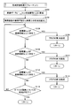
- FIG. 4 is a flowchart showing the overall processing procedure in the imaging system 1 according to the first embodiment of the present invention.
- FIG. 5 is a flowchart showing the contents of the color gamut evaluation processing subroutine (1) shown in FIG.
- FIG. 6 is a flowchart showing the contents of the lighting environment switching subroutine shown in FIG.
- superscript (1) data etc. obtained by the first imaging are indicated by superscript (1) and obtained by the second imaging Data and the like are indicated with superscript (2) .
- imaging device 200 captures an object OBJ, and outputs imaging data g (1) according to object OBJ (step S2).
- the imaging device 200 performs an imaging operation in response to an operation by a user or the like.
- the spectral reflectance estimation unit 130 acquires the spectral radiance E (1) measured by the spectral radiance meter 300 (step S4), and calculates the spectral reflectance estimation matrix W (1) (step S6). ).
- the linear correction unit 102 linearizes the image data g (1) i (m, n) corresponding to one pixel output from the imaging device 200 to generate linear image data gc (1) i (m, n ). ) Is generated (step S8). Then, the color conversion unit 134 outputs the spectral radiance E (1) acquired in step S4, the spectral reflectance estimation matrix W (1) calculated in step S6, and the linear image data gc generated in step S8.
- Image data g ' (1) XYZ (m, n) is calculated using i (m, n) (step S10). Furthermore, it is determined whether the processing for all the pixels included in the imaging data g (1) is completed (step S12), and the processing for all the pixels is not completed (NO in step S12), The processes after step S8 are executed again.
- step S12 image data g ' (1) XYZ (m, n) exists in a color range that can be captured by imaging device 200.
- step S14 In order to evaluate whether or not the color gamut evaluation processing subroutine (1) is executed (step S14). As described later, when the evaluation result of the color gamut evaluation processing subroutine (1) in step S14 is output as a "flag" to a memory area provided in the evaluation unit 112 or the like, and the flag is set, This means that the image data g ′ (1) XYZ (m, n) exist outside the color gamut that can be imaged by the imaging device 200.
- the evaluation unit 112 determines whether any flag is set, that is, the image data g ′ (1) XYZ (outside the color gamut that can be imaged by the imaging device 200 ). It is determined whether m, n) exists (step S16). When the flag is set (in the case of YES in step S16), the evaluation unit 112 stores the current spectral radiance E (1) in the primary storage unit 132 (step S18) and from the lighting device 400 In order to switch the illumination light, the illumination environment switching subroutine is executed (step S20).
- the imaging device 200 After execution of the illumination environment switching subroutine, the imaging device 200 captures an image of the object OBJ again, and outputs imaging data g (2) according to the object OBJ (step S22). Subsequently, the spectral reflectance estimation unit 130 acquires the spectral radiance E (2) measured by the spectral radiance meter 300 (step S24), and calculates the spectral reflectance estimation matrix W (2) (step S26). ).
- the linear correction unit 102 linearizes the image data g (2) i (m, n) corresponding to one pixel output from the imaging device 200 to generate linear image data gc (2) i (m, n ). ) Is generated (step S30). Then, the color conversion unit 134 generates the spectral radiance E (1) stored in the primary storage unit 132 in step S18, the spectral reflectance estimation matrix W (2) calculated in step S26, and the signal generated in step S30. Image data g ' (2) XYZ (m, n) is calculated using linear image data gc (2) i (m, n) (step S32). Further, it is determined whether or not processing for all pixels included in imaging data g (2) is completed (step S34), and processing for all pixels is not completed (NO in step S34) The process after step S30 is executed again.
- step S34 coordinate conversion unit 120 converts image data g ′ (2) XYZ (m, n) calculated in step S32 RGB color system image data g ′ RGB (m, n) is converted (step S 54), and then the gamma correction unit 122 converts the image data g ′ RGB (m, n) into color reproduction data gd RGB (m , N) (step S56) and externally output.
- the coordinate conversion unit 120 converts the image data g ′ (1) XYZ (m, n) calculated in step S10 into the RGB color system
- the image data g ′ RGB (m, n) is converted into the image data g ′ RGB (m, n) (step S 58).
- the gamma correction unit 122 converts the image data g ′ RGB (m, n) into color reproduction data gd RGB Convert (step S60), and output it to the outside.
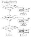
- step S14 the contents of the color gamut evaluation processing subroutine (1) of step S14 will be described.
- coordinate conversion unit 110 converts image data g ′ (1) XYZ (m, n) into coordinate values (x, y) on xy coordinates (step S100).
- the evaluation unit 112 reads the color gamut on the imageable xy coordinates of the imaging device 200 from the evaluation table 114 (step S102).
- the evaluation unit 112 corresponds to the coordinates (x1, y1) and G (green) corresponding to R (red) as shown in FIG. 3 as the coordinate values (x, y) calculated in step S100 It is determined whether it exists on a straight line area (a) connecting x2, y2) (step S104). If the coordinate value (x, y) exists on the linear area (a) (YES in step S104), the evaluation unit 112 sets a flag B (blue) (step S106).
- the evaluation unit 112 calculates the coordinate value (x, y) calculated in step S100 as shown in FIG. It is determined whether or not it exists on a linear region (b) connecting the coordinates (x2, y2) corresponding to G (green) and (x3, y3) corresponding to B (blue) as shown in FIG. Step S108). If the coordinate value (x, y) exists on the linear region (b) (YES in step S108), the evaluation unit 112 sets a flag R (red) (step S110).
- the evaluation unit 112 calculates the coordinate value (x, y) calculated in step S100 as shown in FIG. It is determined whether it exists on a straight line area (c) connecting the coordinates (x3, y3) corresponding to B (blue) and (x1, y1) corresponding to R (red) as shown in FIG. Step S112). If the coordinate value (x, y) exists on the linear region (c) (YES in step S112), the evaluation unit 112 sets a flag G (green) (step S114).
- step S116 it is determined whether or not processing for all pixels included in imaging data g (1) is completed (step S116), and processing for all pixels is not completed (NO in step S116) The process after step S100 is executed again.
- step S116 if the process for all the pixels is completed (YES in step S116), the process proceeds to step S16 in FIG.
- evaluation unit 112 first determines whether flag B (blue) is set (step S200). When flag B (blue) is set (YES in step S200), evaluation unit 112 causes illumination light including a large amount of B (blue) component to be emitted from illumination device 400 toward object OBJ. (Step S202).
- evaluation unit 112 determines whether flag R (red) is set (step S204). When the flag R (red) is set (YES in step S204), illumination light including a large amount of R (red) component is emitted from the illumination device 400 toward the object OBJ (step S206).
- the evaluation unit 112 determines whether the flag G (green) is set (step S208). If the flag G (green) is set (YES in step S208), illumination light including a large amount of G (green) components is emitted from the illumination device 400 toward the object OBJ (step S210).
- the first embodiment of the present invention it is possible to determine the illumination environment at the time of imaging the subject in consideration of the color gamut that can be imaged by the imaging device. Therefore, since the color of the subject can be correctly captured using the imaging device, the spectral reflectance of the subject can be accurately estimated from the captured imaging data. Therefore, even if the color of the subject exists outside the imageable color gamut of the imaging device in the illumination environment where the subject should be imaged, the illumination environment where the imaging should be performed after the spectral reflectance is accurately estimated. The color that will be imaged (observed) can be properly reproduced.
- the display device can also display a color of purity exceeding the imaging capability of the imaging device. It becomes.
- FIG. 7 is a schematic block diagram of an imaging system 2 according to the second embodiment of the present invention.
- imaging system 2 images subject OBJ as in imaging system 1 according to the first embodiment, and performs predetermined image processing (mainly, color reproduction processing) on the imaged image data. After the output, image data (color reproduction data) is output. More specifically, in the imaging system 1 according to the first embodiment, the imaging system 2 employs the image processing apparatus 100A in place of the image processing apparatus 100, and the imaging system 1 is used for the other parts. And the detailed description will not be repeated.
- the illumination device 400 emits illumination light to the object OBJ when the imaging device 200 captures an image of the object OBJ.
- illumination apparatus 400 according to the present embodiment is configured to be able to selectively emit a plurality of illumination lights having different principal wavelengths toward object OBJ in accordance with an instruction from image processing apparatus 100A. That is, as described later, as a result of imaging the object OBJ in a predetermined illumination environment (hereinafter also referred to as “first illumination environment”), the imaging data includes pixels having colors outside the color range that can be imaged by the imaging device 200.
- the illumination device 400 When it is determined that the illumination light is emitted, the illumination device 400 emits another illumination light to the object OBJ so that the color of the pixel falls within the color range that can be captured by the imaging device 200.
- the illumination light from the illumination device 400 forms an illumination environment (hereinafter also referred to as a “second illumination environment”) different from the first illumination environment.
- the image processing apparatus 100A when a pixel having a color outside the color gamut that can be imaged by the imaging device 200 is included in the imaging data, the pixel is out of the color gamut at any position on the color space. It is evaluated whether it has become, and the light emitted from the illumination device 400 to the object OBJ is switched based on the evaluation result (coordinate position).
- the color gamut that can be imaged by the imaging device 200 is determined according to the spectral sensitivity of the imaging element that constitutes the imaging device 200, the characteristics of the wavelength filter (color filter) 404 mounted on the filter wheel 402 It is preferable to determine according to the spectral sensitivity of the element.
- illumination apparatus 400 includes three wavelength filters 404 of R (red), G (green) and B (blue) as main wavelengths. That is, the lighting device 400 is configured to be able to switch and emit reddish illumination light, greenish illumination light, and bluish illumination light. In order to form the first illumination environment, the light generated by the light source 408 may be irradiated as it is without passing through such a wavelength filter 404.
- the image processing apparatus 100A uses the imaging data g (1) obtained by imaging the object OBJ under the first illumination environment and the spectral radiance E (1) measured under the first illumination environment to generate the object OBJ in each pixel. After the spectral reflectance is estimated, imaging data g (1) i (m, n) defined on the RGB color space is XYZ using the estimated spectral reflectance and the spectral radiance E (1). Image data of color system g ′ (1) Convert to XYZ (m, n).
- the image processing apparatus 100A determines whether the image data g ′ (1) XYZ (m, n) exist in a color range that can be captured by the imaging device 200. If any image data g ′ (1) XYZ (m, n) exists outside the color gamut that can be imaged by the imaging device 200, the second illumination environment is irradiated by irradiating a specific illumination light from the illumination device 400. Form.
- the image processing apparatus 100A uses the imaging data g (2) obtained by imaging the object OBJ under the second illumination environment and the spectral radiance E (2) measured under the second illumination environment, and the object at each pixel Image data g (2) i (m, n) defined on the RGB color space by using the estimated spectral reflectance and spectral radiance E (1) after estimating the spectral reflectance of OBJ Is converted to image data g ′ of XYZ color system (2) XYZ (m, n).
- the image processing apparatus 100A uses the corresponding image data g ′ (1) XYZ (m, n) for the pixels existing in the color range that can be imaged by the imaging device 200, and the remaining pixels, ie, the imaging device For pixels existing outside the color gamut that can be imaged at 200, composite image data G XYZ (m, n) is synthesized using the corresponding image data g ' (2) XYZ (m, n). Then, based on the composite image data G XYZ (m, n), color reproduction data of the RGB color system is generated and output.
- the image processing apparatus 100A can capture an image with the imaging device 200.
- composite image data G XYZ (m, n) is generated.
- the image processing apparatus 100A includes a linear correction unit 102A, a first color conversion unit 104, a second color conversion unit 106, coordinate conversion units 110 and 120, an evaluation unit 112A, an evaluation table 114, and the like. , A combining unit 116, a flag table 118, and a gamma correction unit 122.
- the linear correction unit 102A is a unit for linearizing the imaging data g output from the imaging device 200.
- a display device there is a non-linear relationship between an input signal level and an actually displayed luminance level, and such non-linearity is referred to as a gamma characteristic.
- Data g is often output.
- the signal level of the imaging data g and the luminance level detected by each imaging device are non-linear, the image processing to be described later can not be accurately performed, and thus the linear correction unit 102A This imaging data g is linearized.
- the gamma characteristic and the inverse gamma characteristic can be expressed as a function of a power, and therefore, assuming that the inverse gamma value in the imaging device 200 is ⁇ c, the linear correction unit 102A sets imaging data g ( 1) i (m, n) or g (2) i (m, n) the linear image data gc which is respectively linearized (1) i (m, n ) or gc (2) i (m, n) Convert to
- the inverse gamma value ⁇ c is set to a value corresponding to the reciprocal of the gamma value ⁇ d of the display device.
- the imaging data g (1) i (m, n) and g (2) i (m, n) output from the imaging device 200 by one imaging exist for the number of pixels of the imaging device 200.
- the number of imaging data g (1) i (m, n) and g (2) i (m, n) is all 2073600. . Therefore, if the conversion equation as described above is executed as it is, the amount of calculation becomes enormous. If the arithmetic processing capability of the image processing apparatus 100A is sufficiently high, the arithmetic may be directly executed, but it is effective to use a look-up table (LUT) when the arithmetic processing capability is limited. .
- LUT look-up table
- the linear correction unit 102A stores the look-up table 102a in advance, and performs linearization processing by referring to the look-up table 102a.
- the look-up table 102a is a data table in which the result of the above-described conversion equation is stored in advance in association with each of all the signal levels that can be acquired by the input imaging data g.
- the conversion amount corresponding to the signal level of the input imaging data g may be acquired with reference to the look-up table 102a, so the amount of operation can be significantly reduced.
- the main contents of the color reproduction process performed by the color conversion unit 104 and the spectral reflectance estimation unit 110 are the color conversion unit 134 and the spectral reflectance estimation unit 130 in the image forming apparatus 100 according to the first embodiment described above. As this is similar to the color reproduction process to be performed, the detailed description will not be repeated.
- the matrix E indicating the spectral radiance used in the above equation (6) can be set to an arbitrary value. This is observed under the first illumination environment (spectral radiance E (1) ) based on imaging data g (2) obtained by imaging the object OBJ under the second illumination environment (spectral radiance E (2) ) It means that the color of the object OBJ can be reproduced. Therefore, in order to reproduce the color of the object OBJ to be observed under the first illumination environment, it is not necessary to image the object OBJ under the first illumination environment, but it is necessary to perform imaging under another second illumination environment. It means that the captured image data g (2) may be used.
- imaging system 2 has an object of imaging object OBJ so as to be within the imageable color range in imaging device 200.
- the first color conversion unit 104 is a part for generating the image data g ′ (1) from the imaging data gc (1) imaged under the first illumination environment, and It includes a reflectance estimation unit 104a and a color reproduction unit 104b.
- the spectral reflectance estimation unit 104a indicates the spectral radiance E (1) measured by the spectral radiance meter 300 under the first illumination environment and the spectral sensitivity at each wavelength of the imaging device of the imaging device 200 stored in advance. Using the matrix S and the autocorrelation matrix A stored in advance, the matrix operation of the above equations (3) and (4) is executed to calculate a spectral reflectance estimation matrix W (1) . Then, the spectral reflectance estimation unit 104a outputs the calculated spectral reflectance estimation matrix W (1) to the color reproduction unit 104b.
- the cycle in which the spectral reflectance estimation unit 104 a calculates the spectral reflectance estimation matrix W is the same as the imaging cycle in the imaging device 200, the measurement cycle of the spectral radiance by the spectral radiance meter 300 is imaged If it is later than the period, the spectral reflectance estimation matrix W may be calculated at the measurement period of the spectral radiance. Alternatively, when the illumination environment of the object OBJ hardly changes, the spectral reflectance estimation matrix W may be calculated only when the spectral radiance output from the spectral radiance meter 300 changes.
- the color reproduction unit 104 b includes the linear image data gc (1) output from the linear correction unit 102 A, the spectral reflectance estimation matrix W (1) output from the spectral reflectance estimation unit 104 a, and the spectral radiance meter 300. Using the measured spectral radiance E (1) and the matrix h indicating the value of the color matching function at each wavelength stored in advance, the matrix operation of the above equation (6) is executed, and the image data g ′ ( 1) Calculate XYZ .
- the second color conversion unit 106 when the second illumination environment is changed from the first illumination environment to the second illumination environment as described later, the second color conversion unit 106 generates an image from the imaging data gc (2) imaged under the second illumination environment A portion for generating data g ′ (2) , which includes a spectral reflectance estimation unit 106 a and a color reproduction unit 106 b.
- the spectral reflectance estimation unit 106a includes the spectral radiance E (2) measured by the spectral radiance meter 300 under the second illumination environment, and the imaging device 200 stored in advance.
- the spectral reflectance estimation matrix W (2) is calculated using the matrix S indicating the spectral sensitivity at each wavelength of the imaging device and the autocorrelation matrix A stored in advance. Then, the spectral reflectance estimation unit 106a outputs the calculated spectral reflectance estimation matrix W (2) to the color reproduction unit 106b.
- the color reproduction unit 106 b includes the linear image data gc (2) output from the linear correction unit 102 A, the spectral reflectance estimation matrix W (2) output from the spectral reflectance estimation unit 106 a, and the first illumination environment.
- Image data g ′ (2) XYZ is calculated using the spectral radiance E (1) measured by the spectral radiance meter 300 and the matrix h indicating the value of the color matching function at each wavelength stored in advance. .
- the combining unit 116 selects a specific one of the pixel data included in the image data g ′ (1) XYZ and the pixel data included in the image data g ′ (2) XYZ according to the map data of the flag table 118 described later. Are combined with a specific one of them to generate composite image data G.sub.XYZ .
- Coordinate conversion unit 120 the synthetic image data G XYZ of the XYZ color system generated by the synthesis unit 116 converts the synthesized image data G RGB in the RGB color system, and outputs it to the gamma correction unit 122. That is, the coordinate conversion unit 120 converts the color space of the composite image data G RGB and outputs the result.
- the gamma correction unit 122 performs conversion processing reverse to the conversion processing in the linear correction unit 102A. More specifically, the gamma correction unit 122 performs the color reproduction data gd RGB on the composite image data G RGB (m, n) of the RGB color system according to the following arithmetic expression using the gamma value ⁇ d of the display device. Convert to (m, n).
- gd RGB (m, n) G RGB (m, n) ⁇ d
- the gamma value ⁇ d of the display device is set to “2.2” or the like as an example.
- the gamma correction unit 122 performs arithmetic processing using a look-up table (LUT). More specifically, the gamma correction unit 122 stores the look-up table 122a in advance, and performs gamma correction processing by referring to the look-up table 122a.
- the look-up table 122a is a data table in which the result of the above-described conversion equation is stored in advance in association with each of all possible signal levels of the input composite image data G RGB . In the actual linearization operation, the conversion amount corresponding to the signal level of the input composite image data G RGB may be acquired with reference to the look-up table 122a, so the amount of operation can be significantly reduced.
- the contents of the look-up table 122a differ depending on the gamma value ⁇ d, when the gamma value ⁇ d is changed, the contents of the look-up table 122a also need to be changed.
- the evaluation unit 112A determines whether the imaging data g (1) imaged under the first illumination environment is within a color range that can be imaged by the imaging device 200. evaluate. Then, when the evaluation unit 112A evaluates that the imaging data g (1) includes a color outside the color gamut that can be imaged by the imaging device 200, the color emitted by the object OBJ is within the color range that can be imaged by the imaging device 200.
- the illumination device 400 emits specific illumination light to form a second illumination environment. Since it is necessary to evaluate the presence or absence in such a color gamut in the color space of the XYZ color system, the evaluation unit 112A determines that the image data g ′ (1 ) Evaluate XYZ .
- the color gamut evaluation process in evaluation unit 112A is the same as the color gamut evaluation process in evaluation unit 112 of image forming apparatus 100 according to the first embodiment described above, and therefore detailed description will not be repeated.
- each sample point moves in the blue direction (lower left direction on the xy coordinates) in xy coordinates as a whole. . That is, by changing the illumination environment, the sample point (hereinafter also referred to as “correction target”) existing outside the color gamut in FIG. 2A emits yellow having a lower purity. It falls within the imageable color range of the device 200. As a result, the color of the portion corresponding to the correction target of the object OBJ can be captured within the imageable color range of the imaging device 200.
- Image data corresponding to imaging data g (1) which should have been imaged under the first illumination environment from imaging data g (2) imaged under the second illumination environment as shown in the above-mentioned equation (6) g ' (2) can generate XYZ . Therefore, while using the image data g ' (2) XYZ generated from the imaging data g (2) captured under the second illumination environment for the pixels to be corrected, the first illumination environment is used for the remaining pixels.
- the color reproduction data gd can be generated by using the image data g ′ (1) XYZ generated from the imaging data g (1) picked up below.
- FIG. 2C should be generated under the first illumination environment shown in FIG. 2A based on the imaging data g (2) imaged under the second illumination environment shown in FIG. 2B. The case where the image data g ' (2) XYZ which had been generated is generated is shown. By performing such color reproduction processing, even if the color is out of the color gamut that can be imaged by the imaging device 200, color reproduction can be performed accurately.
- FIG. 8 is a diagram for describing an outline of the image combining process according to the present embodiment.
- a portion (correction target) having a color that is out of the color gamut that can be imaged by imaging device 200 is specified.
- the image pickup data g (1) image data g of a portion excluding the corrected generated from '(1), the correction object generated from the captured imaged data g (2) in the second illumination environment
- the image data g ′ (2) of the corresponding part is synthesized and generated as synthesized image data G.
- evaluation unit 112A evaluates at which position on the xy coordinates the color is out of the color gamut, and selects the illumination light according to this position.
- the switching process of the illumination light in evaluation unit 112A is the same as the switching process of the illumination light in evaluation unit 112 of image forming apparatus 100 according to the first embodiment described above, and therefore detailed description will not be repeated.
- the evaluation unit 112A stores coordinate values (x, y) sequentially output from the coordinate conversion unit 110 by the number corresponding to one imaging by the imaging device 200, and the imaging device 200 defined in advance on xy coordinates. It is determined whether or not there is something outside the color gamut that can be imaged. Then, when there is a pixel having a color existing outside the color gamut that can be captured by the imaging device 200, the evaluation unit 112A stores information (flag) for specifying the position of the pixel in the flag table 118. . That is, the evaluation unit 112A classifies pixels having colors present in a color gamut that can be imaged by the imaging device 200 and pixels that have colors present outside the color gamut that can be imaged by the imaging device 200.
- the evaluation unit 112A determines at which position the coordinate value (x, y) falls outside the color gamut. evaluate. Then, the evaluation unit 112A outputs a selection command of the illumination light to the illumination device 400 according to the position. As described above, specifically, the evaluation unit 112A determines whether the coordinate value (x, y) exists in any linear region connecting the respective coordinates corresponding to R, G, B on the xy coordinates. Judging by
- the color gamut that can be imaged by the imaging device 200 which is defined in advance on the xy coordinates, is stored in advance in the evaluation table 114. Further, since the color gamut that can be imaged by the imaging device 200 depends on the characteristics of the imaging elements that constitute the imaging device 200, the type or individual of the imaging device 200 is acquired in advance by experiment or simulation.
- FIG. 9 is a diagram for explaining the data structure stored in flag table 118 shown in FIG.
- the flag table 118 according to the present embodiment has a data structure corresponding to the pixel arrangement (for example, 1920 ⁇ 1080 pixels) in the imaging device 200.
- the initial values of the flag table 118 are all set to "0".
- the evaluation unit 112A selects pixels having colors that exist outside the color gamut that can be imaged by the imaging device 200 among the imaging data g ′ (1) imaged in the first illumination environment.
- the flag of the position corresponding to the pixel in the flag table 118 is set to “1”.
- the evaluation unit 112A performs the above-described process on all the pixels included in the imaging data g ′ (1) .
- a map is formed which shows, among the pixels captured by the imaging device 200, those whose colors exist outside the color gamut that can be captured by the imaging device 200.
- the synthesizing unit 116 specifies the image data g ′ (2) necessary for generating the synthesized image data G with reference to the map formed in the flag table 118 as described above.
- the second color conversion unit 106 may calculate the image data g ′ (2) corresponding to all the pixels based on the imaging data g (2) captured under the second illumination environment.
- the calculation processing of the image data g ′ (2) has a relatively large amount of operation, referring to the flag table 118 via the combining unit 116, only the pixels necessary for generating the combined image data G It is preferable to generate data g ′ (2) .
- the color is specified in addition to information for specifying a pixel having a color that is out of the color gamut that can be captured by the imaging device 200 among the imaging data g ′ (1). You may store information for
- FIG. 10 is a view showing another form of the flag table 118 shown in FIG. Referring to FIG. 10, in the flag table 118 of this embodiment, “R”, “G”, and “B” for specifying the color at the position corresponding to the pixel having the color existing outside the imageable color gamut. Values such as are stored.
- R”, “G”, and “B” for specifying the color at the position corresponding to the pixel having the color existing outside the imageable color gamut. Values such as are stored.
- FIG. 11 is a flowchart showing the overall processing procedure in the imaging system 2 according to the second embodiment of the present invention.
- FIG. 12 is a flowchart showing the contents of the color gamut evaluation processing subroutine (2) shown in FIG.
- imaging device 200 captures an object OBJ in the first illumination environment, and outputs imaging data g (1) according to object OBJ (step S2).
- the imaging device 200 performs an imaging operation in response to an operation by a user or the like.
- the spectral reflectance estimation unit 104a acquires the spectral radiance E (1) measured by the spectral radiance meter 300 (step S4), and calculates the spectral reflectance estimation matrix W (1) (step S6). ).
- the linear correction unit 102A linearizes the imaging data g (1) i (m, n) corresponding to one pixel output from the imaging device 200 to generate linear image data gc (1) i (m, n ). ) Is generated (step S8). Then, the color reproduction unit 104b uses the spectral radiance E (1) acquired in step S4, the spectral reflectance estimation matrix W (1) calculated in step S6, and the linear image data gc generated in step S8. (1) Image data g ' (1) XYZ (m, n) is calculated using i (m, n) (step S10). Furthermore, it is determined whether the processing for all the pixels included in the imaging data g (1) is completed (step S12), and the processing for all the pixels is not completed (NO in step S12), The processes after step S8 are executed again.
- step S12 image data g ' (1) XYZ (m, n) exists in a color range that can be captured by imaging device 200.
- step S14 The evaluation result of the color gamut evaluation processing subroutine (2) is stored in the flag table 118.
- the evaluation unit 112A determines whether the flag is set in the flag table 118, that is, the image data g ′ (1) XYZ (outside the color gamut that can be imaged by the imaging device 200 ). It is determined whether m, n) exists (step S16). When the flag is set (YES in step S16), the color reproduction unit 106b stores the spectral radiance E (1) at the present time (step S18). Then, the evaluation unit 112A executes a lighting environment switching subroutine in order to switch the illumination light from the lighting device 400 (step S20).
- the imaging device 200 After execution of the illumination environment switching subroutine, the imaging device 200 images the object OBJ again under the second illumination environment, and outputs imaging data g (2) according to the object OBJ (step S22). Subsequently, the spectral reflectance estimation unit 106a acquires the spectral radiance E (2) measured by the spectral radiance meter 300 (step S24), and calculates the spectral reflectance estimation matrix W (2) (step S26). ).
- the evaluation unit 112A refers to the flag table 118 to specify pixels necessary for generating the composite image data G (step S28).
- the linear correction unit 102A linearizes g (2) i (m, n) corresponding to the pixels necessary for the composite image data G out of the imaging data g (2) output from the imaging device 200 and generates linear image data.
- gc (2) i (m, n) is generated (step S30).
- the color reproduction unit 106b stores the spectral radiance E (1) stored in advance in step S18, the spectral reflectance estimation matrix W (2) calculated in step S26, and the linear image data gc generated in step S30.
- step S32 Image data g ' (2) XYZ (m, n) is calculated using i (m, n) (step S32). Furthermore, it is judged whether or not processing for all pixels necessary for composite image data G is completed (step S34), and processing for all pixels necessary for composite image data G is not completed (step S34) The process of step S28 and subsequent steps is executed again.
- combining unit 116 calculates the image data g ′ calculated in step S32 (2) XYZ (M, n) and data excluding the pixel corresponding to the image data g ′ (2) XYZ (m, n) among the image data g ′ (1) XYZ (m, n) calculated in step S 10
- the composite image data G XYZ are generated from (step S36).
- the coordinate conversion unit 120 converts the synthesized image data G XYZ calculated in step S36 in the composite image data G RGB in the RGB color system (step S38), followed by gamma correction unit 122, the synthetic image data G RGB is converted to color reproduction data gd RGB (step S40), and output to the outside.
- the combining unit 116 combines the image data g ′ (1) XYZ (m, n) calculated in step S10 with the combined image data G XYZ Output (step S42). Furthermore, the coordinate conversion unit 120 converts the synthesized image data G XYZ output in step S40 in the composite image data G RGB in the RGB color system (step S44), followed by gamma correction unit 122, the synthetic image data G RGB is converted to color reproduction data gd RGB (step S46), and output to the outside.
- coordinate conversion unit 110 converts image data g ′ (1) XYZ (m, n) into coordinate values (x, y) on xy coordinates (step S100). Then, the evaluation unit 112A reads the color gamut on the imageable xy coordinates of the imaging device 200 from the evaluation table 114 (step S102).
- the coordinate values (x, y) calculated in step S100 correspond to the coordinates (x1, y1) and G (green) corresponding to R (red) as shown in FIG. It is determined whether it exists on a straight line area (a) connecting x2, y2) (step S104). If the coordinate value (x, y) exists on the linear area (a) (YES in step S104), the evaluation unit 112A sets the flag B (blue) (step S106).
- the evaluation unit 112A calculates the coordinate value (x, y) calculated in step S100 as shown in FIG. It is determined whether or not it exists on a linear region (b) connecting the coordinates (x2, y2) corresponding to G (green) and (x3, y3) corresponding to B (blue) as shown in FIG. Step S108). If the coordinate value (x, y) exists on the linear area (b) (YES in step S108), the evaluation unit 112A sets a flag R (red) (step S110).
- the evaluation unit 112A determines that the coordinate value (x, y) calculated in step S100 It is determined whether it exists on a straight line area (c) connecting the coordinates (x3, y3) corresponding to B (blue) and (x1, y1) corresponding to R (red) as shown in FIG. Step S112). If the coordinate value (x, y) exists on the linear region (c) (YES in step S112), the evaluation unit 112A sets a flag G (green) (step S114).
- the evaluation unit 112A sets a flag "1" at the position corresponding to the target pixel in the flag table 118 (step S116).
- step S118 it is determined whether the processing for all the pixels included in the imaging data g (1) is completed (step S118), and the processing for all the pixels is not completed (NO in step S118), The processes after step S104 are performed again.
- step S116 if the process for all the pixels is completed (YES in step S116), the process proceeds to step S16 in FIG.
- the contents of the illumination environment switching subroutine of step S20 are the same as the contents of the flowchart shown in FIG. 6 described in the first embodiment described above, and therefore detailed description will not be repeated.
- a pixel having a color outside the color gamut that can be imaged by the imaging device 200 is one of R (red), G (green), and B (blue)
- the process under the illumination environment may be performed multiple times.
- the second illumination environment is formed multiple times according to the set flags, and imaging data is acquired by imaging the object OBJ under each second illumination environment, as described above.
- composite image data may be generated using data of necessary pixels among the image data calculated from the respective imaging data.
- the second embodiment of the present invention it is possible to determine the illumination environment at the time of imaging the subject in consideration of the color gamut that can be imaged by the imaging device. Therefore, since the color of the subject can be correctly captured using the imaging device, the spectral reflectance of the subject can be accurately estimated from the captured imaging data. Therefore, even if the color of the subject exists outside the imageable color gamut of the imaging device in the illumination environment where the subject should be imaged, the illumination environment where the imaging should be performed after the spectral reflectance is accurately estimated. The color that will be imaged (observed) can be properly reproduced.
- the display device can also display a color of purity exceeding the imaging capability of the imaging device. It becomes.
- the second embodiment of the present invention it is possible to generate composite image data by estimating spectral reflectance only for pixels having colors outside the color gamut that can be imaged by the imaging device. The increase can be suppressed.
- FIG. 13 is a schematic configuration diagram of a computer that realizes image processing apparatus 100 # according to the modification of the embodiment of the present invention.
- the computer includes a computer main body 150 equipped with a flexible disk (FD) drive 166 and a compact disk-read only memory (CD-ROM) drive 168, a monitor 152, a keyboard 154, and a mouse. And 156.
- FD flexible disk
- CD-ROM compact disk-read only memory
- the computer main body 150 further includes a central processing unit (CPU) 160 which is an arithmetic device, a memory 162, a fixed disk 164 which is a storage device, and a communication interface 170 which are mutually connected by a bus.
- CPU central processing unit
- Image processing apparatus 100 # can be realized by CPU 160 executing software using computer hardware such as memory 162.
- such software is stored in a recording medium such as the FD 166a or the CD-ROM 168a, or distributed via a network or the like.
- such software is read from the recording medium by the FD drive device 166, the CD-ROM drive device 168, or the like, or received by the communication interface 170 and stored in the fixed disk 164.
- it is read from the fixed disk 164 to the memory 162 and executed by the CPU 160.
- the monitor 152 is a display unit for displaying information output by the CPU 160, and is configured of, for example, a liquid crystal display (LCD) or a cathode ray tube (CRT).
- the mouse 156 receives an instruction from a user corresponding to an operation such as a click or a slide.
- the keyboard 154 receives an instruction from the user corresponding to the key input.
- the CPU 160 is an operation processing unit that executes various operations by sequentially executing programmed instructions.
- the memory 162 stores various types of information in accordance with program execution of the CPU 160.
- the communication interface 170 is a device for establishing communication between the computer and the imaging device 200, the spectral radiation luminance meter 300, the lighting device 400 (FIG.
- the fixed disk 164 is a non-volatile storage device that stores programs executed by the CPU 160, predetermined data, and the like.
- another output device such as a printer may be connected to the computer as necessary.
- the program according to the present embodiment is to execute a process by calling a required module in a predetermined arrangement at a predetermined timing among program modules provided as a part of an operating system (OS) of a computer. It may be. In that case, the program itself does not include the above module, and the processing is executed in cooperation with the OS. A program not including such a module may also be included in the program according to the present invention.
- OS operating system
- the program according to the present embodiment may be provided by being incorporated into a part of another program. Also in this case, the program itself does not include a module included in the other program, and the process is executed in cooperation with the other program.
- the configuration in which the spectral radiance meter 300 directly measures the illumination environment (spectral radiance) of the object OBJ is exemplified, but the illumination light irradiated to the object OBJ is mainly
- the spectral radiance may be measured in advance instead of directly measuring the spectral radiance. That is, spectral radiance is measured in advance in association with each illumination light selectively emitted from illumination device 400, and illumination light emitted from illumination device 400 among the previously measured spectral radiances. Depending on the selection of, the corresponding spectral radiance may be read out.
- the illumination light emitted from the illumination device 400 may be emitted only when the imaging data of the object OBJ is outside the color gamut that can be imaged by the imaging device 200. That is, at the time of normal imaging, the object OBJ is measured under a desired illumination environment, and under this illumination environment, the illumination device is the first time when the imaging data of the object OBJ is outside the color gamut that can be imaged by the imaging device 200. It is good also as operation which irradiates specific illumination light from 400.
Landscapes
- Physics & Mathematics (AREA)
- Spectroscopy & Molecular Physics (AREA)
- Engineering & Computer Science (AREA)
- Multimedia (AREA)
- Signal Processing (AREA)
- General Physics & Mathematics (AREA)
- Facsimile Image Signal Circuits (AREA)
- Color Image Communication Systems (AREA)
Abstract
Lorsqu'un système d'éclairage bleuâtre est appliqué à un objet (OBJ), chacun des points échantillon est décalé dans la direction bleue globalement sur le système de coordonnées de chromaticité xy (direction en bas à gauche sur le système de coordonnées de chromaticité xy). Cela revient à dire qu'en changeant un environnement d'éclairage, le point échantillon qui a existé hors de la région de couleur (un point de couleur jaune de pureté relativement haute) est décalé vers une couleur jaune de pureté inférieure et le point est contenu dans la région de couleur qui peut être capturée par un dispositif d'imagerie. Il en résulte que toutes les couleurs de l'objet (OBJ) peuvent être capturées dans la région de couleur qui peut être capturée par le dispositif d'imagerie. Cela permet une estimation précise de la réflectance spectrale de l'objet (OBJ) et une reproduction de la couleur hors de la région de couleur.
Applications Claiming Priority (4)
| Application Number | Priority Date | Filing Date | Title |
|---|---|---|---|
| JP2008027614A JP4588076B2 (ja) | 2008-02-07 | 2008-02-07 | 撮像方法および撮像システム |
| JP2008-027615 | 2008-02-07 | ||
| JP2008027615A JP2009188807A (ja) | 2008-02-07 | 2008-02-07 | 撮像方法および撮像システム |
| JP2008-027614 | 2008-10-28 |
Publications (1)
| Publication Number | Publication Date |
|---|---|
| WO2009098968A1 true WO2009098968A1 (fr) | 2009-08-13 |
Family
ID=40952046
Family Applications (1)
| Application Number | Title | Priority Date | Filing Date |
|---|---|---|---|
| PCT/JP2009/051245 Ceased WO2009098968A1 (fr) | 2008-02-07 | 2009-01-27 | Procédé d'imagerie et système d'imagerie |
Country Status (1)
| Country | Link |
|---|---|
| WO (1) | WO2009098968A1 (fr) |
Cited By (1)
| Publication number | Priority date | Publication date | Assignee | Title |
|---|---|---|---|---|
| US10911731B2 (en) * | 2015-03-31 | 2021-02-02 | Nikon Corporation | Image-capturing device |
Citations (4)
| Publication number | Priority date | Publication date | Assignee | Title |
|---|---|---|---|---|
| JPS6478133A (en) * | 1987-09-21 | 1989-03-23 | Nippon Telegraph & Telephone | Measuring method for spectral reflection factor |
| JPH11341501A (ja) * | 1998-05-26 | 1999-12-10 | Seiko Epson Corp | 電子写真撮像装置、電子写真撮像方法、電子写真撮像制御プログラムを記録した媒体 |
| JP2004289585A (ja) * | 2003-03-24 | 2004-10-14 | Japan Science & Technology Agency | 画像の取得方法 |
| JP2007274637A (ja) * | 2006-03-31 | 2007-10-18 | National Institute Of Information & Communication Technology | 映像処理装置 |
-
2009
- 2009-01-27 WO PCT/JP2009/051245 patent/WO2009098968A1/fr not_active Ceased
Patent Citations (4)
| Publication number | Priority date | Publication date | Assignee | Title |
|---|---|---|---|---|
| JPS6478133A (en) * | 1987-09-21 | 1989-03-23 | Nippon Telegraph & Telephone | Measuring method for spectral reflection factor |
| JPH11341501A (ja) * | 1998-05-26 | 1999-12-10 | Seiko Epson Corp | 電子写真撮像装置、電子写真撮像方法、電子写真撮像制御プログラムを記録した媒体 |
| JP2004289585A (ja) * | 2003-03-24 | 2004-10-14 | Japan Science & Technology Agency | 画像の取得方法 |
| JP2007274637A (ja) * | 2006-03-31 | 2007-10-18 | National Institute Of Information & Communication Technology | 映像処理装置 |
Non-Patent Citations (1)
| Title |
|---|
| MATSUMOTO T. ET AL.,: "Multi-band Camera o Mochiita Gazo no Kiroku to Saigen [Record and Reproduction of Images by Means of a Multi-band Camera", PROCEEDINGS OF THE 2001 IEICE GENERAL CONFERENCE [PROCEEDINGS OF THE 2001 IEICE GENERAL CONFERENCE], 7 March 2001 (2001-03-07), pages 313 * |
Cited By (1)
| Publication number | Priority date | Publication date | Assignee | Title |
|---|---|---|---|---|
| US10911731B2 (en) * | 2015-03-31 | 2021-02-02 | Nikon Corporation | Image-capturing device |
Similar Documents
| Publication | Publication Date | Title |
|---|---|---|
| JP6974397B2 (ja) | 測定装置 | |
| JP4120841B2 (ja) | プロジェクタの色補正方法 | |
| JP4935822B2 (ja) | 画像処理装置、画像処理方法、画像処理プログラム | |
| US7884968B2 (en) | System for capturing graphical images using hyperspectral illumination | |
| KR100278642B1 (ko) | 칼라 영상 처리장치 및 방법 | |
| US10231600B2 (en) | Image processing apparatus | |
| JP5257375B2 (ja) | 画像処理装置および画像処理方法 | |
| JP5195430B2 (ja) | 画像処理方法、画像処理プログラム、画像処理装置、カメラ | |
| JPH09214787A (ja) | 画像処理装置及び方法 | |
| JP2012154711A (ja) | 分光スペクトル推定装置および学習スペクトル生成方法 | |
| JP4262359B2 (ja) | 色再現システム | |
| JP2011109620A (ja) | 撮像装置および画像処理方法 | |
| JP2010139324A (ja) | 色ムラ測定方法、および色ムラ測定装置 | |
| US7864235B2 (en) | Imaging device and imaging method including generation of primary color signals | |
| JP4174707B2 (ja) | 分光測定システム、色再現システム | |
| JP2009188807A (ja) | 撮像方法および撮像システム | |
| JPH10108031A (ja) | 画像処理装置及び方法及び記録媒体 | |
| JP5120936B2 (ja) | 画像処理装置および画像処理方法 | |
| JP4588076B2 (ja) | 撮像方法および撮像システム | |
| WO2009098968A1 (fr) | Procédé d'imagerie et système d'imagerie | |
| JP2009182845A (ja) | 画像処理装置および画像処理方法 | |
| JP4400146B2 (ja) | 分光画像データ処理方法および分光画像データ処理装置 | |
| JP2000337965A (ja) | 撮像系の光源の分光分布測定方法 | |
| JP5029187B2 (ja) | 色座標変換装置、撮像装置、色座標変換プログラム、色座標変換方法 | |
| JP2022006624A (ja) | 校正装置、校正方法、校正プログラム、分光カメラ、及び情報処理装置 |
Legal Events
| Date | Code | Title | Description |
|---|---|---|---|
| 121 | Ep: the epo has been informed by wipo that ep was designated in this application |
Ref document number: 09707477 Country of ref document: EP Kind code of ref document: A1 |
|
| NENP | Non-entry into the national phase |
Ref country code: DE |
|
| 122 | Ep: pct application non-entry in european phase |
Ref document number: 09707477 Country of ref document: EP Kind code of ref document: A1 |