WO2009099013A1 - 移動通信システム、受信装置及び方法 - Google Patents
移動通信システム、受信装置及び方法 Download PDFInfo
- Publication number
- WO2009099013A1 WO2009099013A1 PCT/JP2009/051626 JP2009051626W WO2009099013A1 WO 2009099013 A1 WO2009099013 A1 WO 2009099013A1 JP 2009051626 W JP2009051626 W JP 2009051626W WO 2009099013 A1 WO2009099013 A1 WO 2009099013A1
- Authority
- WO
- WIPO (PCT)
- Prior art keywords
- matrix
- symbol
- transmission
- subcarrier
- transmitted
- Prior art date
- Legal status (The legal status is an assumption and is not a legal conclusion. Google has not performed a legal analysis and makes no representation as to the accuracy of the status listed.)
- Ceased
Links
Images




Classifications
-
- H—ELECTRICITY
- H04—ELECTRIC COMMUNICATION TECHNIQUE
- H04B—TRANSMISSION
- H04B7/00—Radio transmission systems, i.e. using radiation field
- H04B7/02—Diversity systems; Multi-antenna system, i.e. transmission or reception using multiple antennas
- H04B7/04—Diversity systems; Multi-antenna system, i.e. transmission or reception using multiple antennas using two or more spaced independent antennas
- H04B7/0413—MIMO systems
-
- H—ELECTRICITY
- H04—ELECTRIC COMMUNICATION TECHNIQUE
- H04J—MULTIPLEX COMMUNICATION
- H04J11/00—Orthogonal multiplex systems, e.g. using WALSH codes
- H04J11/0023—Interference mitigation or co-ordination
- H04J11/0026—Interference mitigation or co-ordination of multi-user interference
- H04J11/0036—Interference mitigation or co-ordination of multi-user interference at the receiver
- H04J11/0046—Interference mitigation or co-ordination of multi-user interference at the receiver using joint detection algorithms
-
- H—ELECTRICITY
- H04—ELECTRIC COMMUNICATION TECHNIQUE
- H04L—TRANSMISSION OF DIGITAL INFORMATION, e.g. TELEGRAPHIC COMMUNICATION
- H04L25/00—Baseband systems
- H04L25/02—Details ; arrangements for supplying electrical power along data transmission lines
- H04L25/03—Shaping networks in transmitter or receiver, e.g. adaptive shaping networks
- H04L25/03006—Arrangements for removing intersymbol interference
- H04L25/03159—Arrangements for removing intersymbol interference operating in the frequency domain
-
- H—ELECTRICITY
- H04—ELECTRIC COMMUNICATION TECHNIQUE
- H04L—TRANSMISSION OF DIGITAL INFORMATION, e.g. TELEGRAPHIC COMMUNICATION
- H04L25/00—Baseband systems
- H04L25/02—Details ; arrangements for supplying electrical power along data transmission lines
- H04L25/03—Shaping networks in transmitter or receiver, e.g. adaptive shaping networks
- H04L25/03006—Arrangements for removing intersymbol interference
- H04L25/03178—Arrangements involving sequence estimation techniques
- H04L25/03203—Trellis search techniques
- H04L25/03216—Trellis search techniques using the M-algorithm
-
- H—ELECTRICITY
- H04—ELECTRIC COMMUNICATION TECHNIQUE
- H04L—TRANSMISSION OF DIGITAL INFORMATION, e.g. TELEGRAPHIC COMMUNICATION
- H04L25/00—Baseband systems
- H04L25/02—Details ; arrangements for supplying electrical power along data transmission lines
- H04L25/03—Shaping networks in transmitter or receiver, e.g. adaptive shaping networks
- H04L25/03891—Spatial equalizers
-
- H—ELECTRICITY
- H04—ELECTRIC COMMUNICATION TECHNIQUE
- H04L—TRANSMISSION OF DIGITAL INFORMATION, e.g. TELEGRAPHIC COMMUNICATION
- H04L27/00—Modulated-carrier systems
- H04L27/26—Systems using multi-frequency codes
- H04L27/2601—Multicarrier modulation systems
- H04L27/2647—Arrangements specific to the receiver only
Definitions
- the present invention relates to the technical field of mobile communication, and more particularly to a mobile communication system, a receiving apparatus, and a method in which single carrier MIMO (Multiple Input Multiple Output) transmission is performed.
- single carrier MIMO Multiple Input Multiple Output
- the multicarrier transmission scheme is a scheme in which a frequency band is divided into a plurality of narrow bands (subcarriers) and signals are transmitted independently on each subcarrier.
- OFDMA Orthogonal Frequency Division Multiple Access
- the Orthogonal Frequency Division Multiple Access (OFDMA) scheme increases frequency utilization efficiency and increases speed and capacity by arranging subcarriers so that the subcarriers are orthogonal to each other.
- OFDMA Orthogonal Frequency Division Multiple Access
- inter-subcarrier interference can be effectively suppressed, and signals can be transmitted in parallel using each subcarrier, so that the length of one symbol can be increased.
- multipath interference can be effectively suppressed by ensuring a certain guard interval.
- PAPR peak power to average power ratio
- the single carrier transmission method is generally advantageous.
- the SC-FDMA (Single Carrier-Frequency Division Multiple Access) method or the DFT spread OFDM (Discrete Fourier Transform spread OFDM) method is a single carrier method, but can effectively use a wide frequency band.
- the transmission signal is mapped to one of the subcarriers after Fourier transform, and the mapped signal is wirelessly transmitted after inverse Fourier transform.
- the received signal is Fourier transformed, signal components mapped to each subcarrier are extracted, and transmission symbols are estimated.
- Such a single carrier transmission method is desirable from the viewpoint of effectively using the frequency band while reducing PAPR.
- Multipath interference becomes particularly prominent when a higher transmission speed is required. For example, this is particularly noticeable when the data modulation multilevel number is large or when the MIMO multiplex transmission method is used. This greatly affects the deterioration of signal detection accuracy on the receiving side.
- the number of transmission antennas is N
- the assumed number of multipaths is P
- the maximum likelihood determination method MLD on the receiving side: Maximum Likelihood Detection
- MLD on the receiving side Maximum Likelihood Detection
- An object of the present invention is to improve signal detection accuracy on the receiving side when a single carrier MIMO scheme is used and an SC-FDMA scheme is used in a mobile communication system.
- a single carrier MIMO transmission system is used, and a mobile communication system including a transmission apparatus and a reception apparatus is used.
- the transmission apparatus includes a unit that maps a group of symbols in a symbol sequence to be transmitted to a plurality of subcarriers together with a predetermined weight by Fourier transform, a unit that performs inverse Fourier transform on the group of mapped symbols, and inverse Fourier Means for transmitting a signal including the converted symbol from a plurality of transmitting antennas.
- the receiving apparatus performs a Fourier transform on signals received by a plurality of receiving antennas, extracts a signal component mapped to each subcarrier, applies a QR decomposition algorithm to the extracted signal component, and outputs each subcarrier.
- Signal detecting means for estimating the symbols transmitted in (1).
- the signal detection means is a triangular matrix that is a product of a matrix that determines a correspondence relationship between the symbol sequence to be transmitted and a subcarrier, a channel matrix that represents a radio channel state between the transmission and reception antennas, and a certain unitary matrix.
- FIG. 2 shows a partial functional block diagram of a transmission apparatus.
- FIG. 3 is a conceptual diagram showing the contents of calculation performed in a DFT unit 21.
- FIG. 2 shows a partial functional block diagram of a receiving apparatus. It is a figure which shows an example of a signal detection part. The functional block diagram of a more detailed receiving apparatus is shown. It is a figure which shows a mode that the difficulty level which determines the combination of a symbol changes according to the magnitude of a fading correlation.
- a receiving apparatus used in a mobile communication system in which a single carrier MIMO transmission scheme is used is used.
- an SC-FDMA multiple access method is used.
- the receiving apparatus performs Fourier transform on signals received by a plurality of receiving antennas, extracts a signal component mapped to each subcarrier, applies a QR decomposition algorithm to the extracted signal component, and applies each subcarrier.
- Signal detecting means for estimating the symbols transmitted in (1).
- the signal detection means has a product of a matrix W that determines the correspondence between the symbol sequence to be transmitted and a subcarrier, a channel matrix H that represents a radio channel state between the transmission and reception antennas, and a unitary matrix Q H.
- the means for obtaining the unitary matrix so as to be a triangular matrix R the vector obtained by multiplying the unitary matrix Q H by the reception vector Y including the signal component received by each receiving antenna, and the triangular matrix R, Means for estimating a symbol candidate x transmitted from a transmission antenna.
- the QR decomposition algorithm is used on the receiving side to reduce the amount of computation in signal detection and to improve signal detection accuracy Will be able to. By improving the signal detection accuracy, it is possible to save the transmission power required to ensure the required quality. This is particularly advantageous when the transmitting side is a user device. Further, by using the QR decomposition algorithm, equalization processing in the frequency domain and signal separation processing by MLD or the like can be efficiently performed at a time.
- the signal detection means may further include means for preparing a metric for each candidate of the symbol and narrowing down candidates according to the metric.
- the metric may represent a squared Euclidean distance between a received symbol and a symbol candidate in a symbol constellation.
- Permutation control means for providing an instruction signal for rearranging rows or columns of matrix products of the channel matrix and the weight matrix to the decomposition means may be provided in the receiving apparatus.
- the decomposition unit may obtain the triangular matrix and the unitary matrix according to the instruction signal so that the matrix product in which rows or columns are rearranged is equal to a product of a triangular matrix and a unitary matrix.
- the estimation means estimates symbols according to the M algorithm
- the parallel antenna is estimated so that a symbol of a transmission antenna corresponding to stronger received power is estimated before a symbol of a transmission antenna corresponding to weaker received power.
- the replacement control means may prepare the instruction signal.
- the rearrangement control means may prepare the instruction signal so that the component is estimated by the estimation means.
- FIG. 1 schematically shows a mobile communication system used in an embodiment of the present invention.
- FIG. 1 shows a cell 50, user apparatuses 100 1 , 100 2 , 100 3 located in the cell 50, a base station 200, an access gateway 300, and a core network 400.
- one or more user apparatuses perform wireless communication with a base station using a MIMO scheme.
- the user equipment is typically a mobile station, but may be a fixed station.
- SC-FDMA or DFT spread OFDM
- the SC-FDMA scheme may be used for the downlink.
- FIG. 2 shows an example of a transmission device used in a mobile communication system.
- this transmission apparatus is provided in the user apparatus, but in another embodiment, it may be provided in the base station.
- FIG. 2 shows a discrete Fourier transform unit (DFT) 21, a frequency domain mapper 22, an inverse fast Fourier transform unit (IFFT) 23, and a guard interval adding unit (+ CP) 24.
- DFT discrete Fourier transform unit
- IFFT inverse fast Fourier transform unit
- CP guard interval adding unit
- a discrete Fourier transform unit (DFT unit) 21 receives a series of symbol sequences to be transmitted and performs a discrete Fourier transform for each predetermined number of symbols.
- This symbol sequence is typically a sequence of symbols after error correction coding and data modulation, but more generally any suitable symbol sequence.
- the DFT 21 performs discrete Fourier transform for each predetermined number (for example, N DFT ) symbols, and converts a time-domain symbol sequence into a frequency-domain signal.
- N DFT represents the window size or block size of the discrete Fourier transform.
- FIG. 3 is a conceptual diagram for explaining the calculation contents performed in the DFT unit 21.
- X 1 shown on the left side represents a signal transmitted from the first transmission antenna among all N TX transmission antennas.
- the signals x 2 , x 3 , ..., x NTX transmitted from the 2nd, 3rd, ... N TX transmit antennas actually exist, but they are drawn for the sake of simplicity.
- Transmission symbol x 1 requires a note that a comprehensive representation of the N DFT symbols.
- x 1 includes N DFT symbols associated with one point on the symbol constellation. The discrete Fourier transform is equivalent to the weighted addition process of these NDFT symbols.
- the frequency domain mapper 22 in FIG. 2 associates (maps) a group of symbols after DFT with individual subcarriers.
- mapping is performed by mapping each symbol to an available resource unit.
- the available resource units are indicated by scheduling information in the control information received by the transmitting apparatus.
- the present invention does not depend on how the mapping is performed, and a symbol group may be mapped to each subcarrier by any appropriate method.
- the simplest mapping would be associating N DFT symbols after DFT directly to N DFT subcarriers from the low frequency side.
- the inverse fast Fourier transform unit (IFFT) 23 performs inverse fast Fourier transform on the symbol associated with each subcarrier, and converts the frequency domain signal into a time domain signal (transmission symbol).
- FIG. 4 shows an example of a receiving apparatus used in a mobile communication system.
- FIG. 4 shows a guard interval removal unit (-CP) 41, a fast Fourier transform unit (FFT) 42, a frequency domain demapper 43, and a signal detection unit 44.
- -CP guard interval removal unit
- FFT fast Fourier transform unit
- Guard interval remover (-CP) 41 removes the guard interval from the baseband received signal.
- FFT Fast Fourier transform unit 42 performs a fast Fourier transform on the received signal, and converts a time domain signal into a frequency domain signal.
- the frequency domain demapper 43 performs processing complementary to the frequency mapper 22 on the transmission side, and extracts signal components mapped to each subcarrier.
- the signal detection unit 44 narrows down transmission symbol candidates from the signal mapped to each subcarrier, and finally determines what it is.
- the operation will be described next. For convenience of explanation, it is transmitted from the n-th transmission antenna in the transmission apparatus of FIG. 2, to write a transmission symbol sequence input to the DFT21 and x n.
- the transmission symbol sequence xn includes N DFT symbols as elements.
- N DFT represents the window size (block size) of the discrete Fourier transform.
- x n [x n1 x n2 ... x nNDFT ] T
- T represents transposition
- n is a natural number equal to or less than N TX
- N TX is the total number of transmission antennas.
- weighting factor wi applied to the i-th (i is a natural number equal to or smaller than N DFT ) subcarrier in the DFT unit 21 is expressed as follows.
- the received signal yi for the i-th subcarrier can be written as:
- Hi is a channel matrix representing a radio channel state related to the i-th subcarrier.
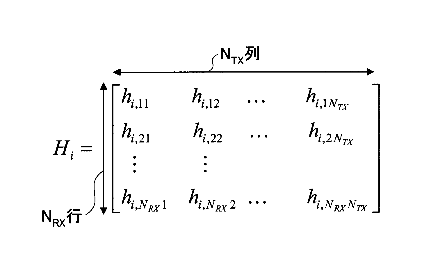
- the channel matrix Hi can be expressed as:
- the channel matrix Hi is a matrix having dimensions of N RX rows ⁇ N TX columns, where N RX is the total number of reception antennas and N TX is the total number of transmission antennas.
- the matrix elements h i, pq of the channel matrix represent the i th subcarrier component in the channel state (transfer function) between the p th receive antenna and the q th transmit antenna.
- the matrix elements of the channel matrix may be derived from the reception state of the pilot signal.
- w i is a vector representing the weighting factor
- 0 NDFT is a 0 vector having N DFT elements.
- xn represents a signal transmitted from the nth transmitting antenna.
- Ni represents the noise component related to the i-th subcarrier.
- a unitary matrix Q is obtained so that the channel matrix H and the weight matrix W can be expressed by a product of a unitary matrix Q and an upper triangular matrix R.
- “H” that is not a superscript represents a channel matrix, while “H” that is a superscript represents a conjugate transposition.
- transmission symbol candidates for x M are narrowed down based on equation (5).
- x M should correspond to any signal point on the symbol constellation.
- e1 (x)
- S1 (S1 ⁇ C) candidates are left in ascending order, and the other candidates are discarded.
- C is the total number of signal points (possible candidate total number) included in the symbol constellation.
- e2 (s M (x), s M-1 (x))
- the second term on the right side is the value of the survival metric derived in the first stage.
- S2 (S2 ⁇ S1C) candidates are left in ascending order of the survival metric e2 (s M (x), s M ⁇ 1 (x)), and the other candidates are discarded.
- the same processing is repeatedly performed, and the survival metric is cumulatively increased for each stage, and the combination of transmission symbols that yields the smallest metric in the final stage is estimated as actually transmitted.
- FIG. 5 shows the details of the signal detection unit of FIG. 4 and mainly executes the above-described operation explanation processing.
- the signal detection unit includes a QR decomposition unit 210, a signal conversion unit 212, a maximum likelihood determination unit 214, and a likelihood output unit 215.
- the maximum likelihood determination unit 214 includes four determination units 216-1, 216-2, 216-3, and 216-4. In order to simplify the illustration, only four determination units are illustrated, but any number of determination units may be prepared according to the number of transmission signals. Since each determination unit has similar processing blocks, the fourth determination unit 216-4 will be described as a representative example.
- the determination unit includes a symbol replica generation unit 218-4, a square Euclidean distance calculation unit 220-4, and a surviving symbol candidate selection unit 222-4.
- processing elements in FIG. 5 and other blocks may be prepared in hardware, software, or a combination thereof.
- Signal conversion unit 212 a plurality of received signals in vector Y to component, by multiplying the conjugate transposition matrix Q H of the unitary matrix Q, performs signal conversion.
- the received signal after such unitary conversion is expressed by the product of the upper triangular matrix R and the transmission symbol x, if noise is ignored.
- the maximum likelihood determination unit 214 narrows down the symbol candidates of the transmission signal by the maximum likelihood determination method (MLD method).
- Symbol replica generation unit 218-4 of the determining unit 216-4 uses matrix elements of the upper triangular matrix R, generates symbol candidates of transmission signals corresponding to the received signal x 4.
- the number of symbol candidates is, for example, C.
- the square Euclidean distance calculation unit 220-4 calculates a square Euclidean distance between the received signal z i after the unitary conversion and the C symbol candidates.
- the squared Euclidean distance represents the survival metric that is the basis for calculating the likelihood.
- the surviving symbol candidate selection unit 222-4 outputs S 1 ( ⁇ C) symbol candidates as surviving symbol candidates based on the squared Euclidean distance for each candidate.
- the likelihood output unit 215 calculates the likelihood or likelihood of the symbol candidate output from the surviving symbol candidate selection unit in the final stage. More specifically, this likelihood is represented by a log likelihood ratio (LLR: Log Likelihood Ratio).
- LLR Log Likelihood Ratio
- the output from the likelihood output unit 215 represents a signal separation result and is transmitted to a demodulator (for example, a turbo decoder) at a subsequent stage.
- N 0 is the average noise power measured at the receiver.
- I is a unit matrix of N TX rows and N TX columns.
- the unitary matrix Q in this case is a matrix having dimensions of N DFT (N TX + N RX ) rows (N DFT ⁇ N TX ) columns.
- the triangular matrix is a square matrix with (N DFT ⁇ N TX ) rows (N DFT ⁇ N TX ) columns, and has the same dimensions as in the above embodiment.
- the received signal Y is a vector of (N DFT ⁇ N RX ) rows and 1 column.
- a vector of (N DFT ⁇ (N TX + N RX )) rows and 1 column is used. It is.
- N DFT ⁇ N TX components are zero.
- reception signal vector Y ′ and the matrix G modified in this way is advantageous from the viewpoint of performing MMSE-type QR decomposition and ZF-type QR decomposition.
- H is a channel matrix.
- W is a weight matrix representing weighting in the frequency direction by DFT.
- F represents a matrix product of the channel matrix H and the weight matrix W.
- x represents a symbol to be transmitted.
- the matrix product F is subjected to QR decomposition.
- the transmitted symbols were estimated in order according to the M algorithm.
- the total number of stages of the M algorithm is N TX ⁇ N DFT .
- Unitary matrix Q H is multiplied to the received signal Y, is estimated from the lowest symbol sequentially performed.
- the product of a matrix A and a column vector s is equal to the product of a matrix A ′ in which the columns in the matrix are replaced and s ′ in which the components of the column vector s are replaced accordingly.
- the column vector x ′ is a column vector in which the components of the column vector x are rearranged in accordance with the replacement method.
- the successive selection of symbol replica candidates is performed for each stage in order from the lower symbol of the transmitted symbol vector. Therefore, the order in which symbols are estimated greatly affects the selection accuracy of surviving symbol replica candidates.
- the columns of the matrix F are rearranged so as to improve the selection accuracy of surviving symbol replica candidates and, consequently, the estimation accuracy of symbols.
- the rows and columns of the matrix are relative concepts. Therefore, unlike the specific description of the present embodiment, when the transmission symbol is defined by a row vector, the rows included in the matrix F are rearranged. Even if the transmission symbol is defined by a column vector as in this embodiment, the generality of the present invention is not lost.
- FIG. 6 shows details of the receiving apparatus shown in FIG.
- FIG. 6 shows a guard interval removal unit (-CP) 41, a fast Fourier transform unit (FFT & demapping) 42, a QR decomposition unit 210, a signal conversion unit 212, an MLD unit 214, and a likelihood output unit 215.
- a channel estimation unit 62 and a rearrangement control unit 64 are shown.
- Guard interval remover (-CP) 41 removes the guard interval from the baseband received signal.
- Fast Fourier transform unit (FFT & demapping) 42 converts a time domain signal into a frequency domain signal by performing a fast Fourier transform on the received signal.
- FFT & demapping is performed in addition to the FFT, but this is not essential.
- the FFT unit and the demapping unit may be prepared separately.
- the channel estimation unit 62 estimates the radio channel state for each subcarrier and derives a channel matrix H.
- a channel matrix is prepared for each subcarrier. Therefore, the entire channel matrix H is a matrix of N RX ⁇ N DFT rows N TX ⁇ N DFT columns.
- the matrix elements of the channel matrix may be derived from the reception state of the pilot signal.
- Signal conversion unit 212 a plurality of received signals in vector Y to component, by multiplying the conjugate transposition matrix Q H of the unitary matrix Q, performs signal conversion.
- the received signal after such unitary conversion is expressed by the product of the upper triangular matrix R and the transmission symbol x, if noise is ignored.
- M maximum likelihood determination method
- the likelihood output unit 215 calculates the likelihood of the symbol candidate output from the surviving symbol candidate selection unit in the final stage. More specifically, this likelihood is represented by a log likelihood ratio (LLR: Log Likelihood Ratio). An output from the likelihood output unit 215 represents a signal separation result and is transmitted to a subsequent decoding unit.
- LLR Log Likelihood Ratio
- the rearrangement control unit 64 gives an instruction signal to the QR decomposition unit 210.
- the indication signal indicates how the columns of the matrix product F of the channel matrix H and the weight matrix W are to be rearranged.
- the above formula (9) is established without depending on a specific rearrangement method. How it should be sorted is not uniquely determined. An appropriate sorting method is determined from some point of view. As will be described later in this modification, the rearrangement of the columns of the product matrix F may be performed from the viewpoint of (Method 1) received power of received symbols (power received by the receiving device), and / or Alternatively, (Method 2) may be performed in units of subcarriers.
- the narrowing-down of surviving symbol replica candidates is applied to the transmission symbols ordered up to the k-th, from the (N TX N SF -k + 1) -th row of the (N TX N SF -k + 1) -th column of the matrix R, respectively.
- the received signal power of the transmission symbol from each transmission antenna is measured, and a transmission symbol having a higher received signal power is estimated with higher priority. This is because if the received power is high, the selection of the symbol replica candidate is less likely to be erroneous.
- the order of the columns of the product matrix F and the components of the transmission symbol x is controlled so that such priorities are realized.
- DFT-MIMO multiplex transmission to which frequency domain spreading is applied according to this method, there are several transmission symbols transmitted after code multiplexing.
- Each component of the transmission symbol transmitted from each transmission antenna gives the same received signal power. Therefore, in this method, a transmission antenna that provides stronger received power is identified, and a symbol transmitted from the transmission antenna is estimated with priority (first) over symbols of other transmission antennas.
- Any appropriate method known in the art may be used as a method of measuring the strength of the received power for the symbols from each transmission antenna. For example, a matrix element of a channel matrix may be used.
- the channel matrix Hi related to the i-th subcarrier is a matrix having dimensions of N RX rows ⁇ N TX columns, where N RX is the total number of reception antennas and N TX is the total number of transmission antennas.
- the matrix elements h i, pq of the channel matrix represent the i th subcarrier component in the channel state (transfer function) between the p th receive antenna and the q th transmit antenna. Therefore,
- rearrangement of the columns of the product matrix F ′ and rearrangement of the components of the transmission symbol x are performed.
- the rearranged transmission symbol x ′ can be written as follows.
- the elements of the symbol x 1 is, to come to the lower column vector, sorting is performed. Furthermore, in which order the subcarrier components x 11 , x 12 , and x 13 in the symbol x 1 are to be estimated is not uniquely determined at this stage. As an example, the younger order of subcarrier numbers may be used. In this case, the rearranged transmission symbol x ′ can be written as follows.
- x ' (x 23 x 22 x 21 x 13 x 12 x 11 ) T Not only the youngest order but also other orders may be used.
- FIG. 7 shows a state in which the difficulty level for determining the combination of symbols varies depending on the magnitude of the fading correlation.
- N TX and the number of reception antennas N RX are both 2.
- Symbol 1 (x 1 ) is transmitted from the first transmitting antenna.
- Symbol 2 (x 2 ) is transmitted from the second transmitting antenna.
- the symbols transmitted from the transmission antenna are data modulated by the QPSK method.
- the symbol is one of predetermined four signal points on the signal point arrangement diagram (constellation). Since there are four possibilities for each of symbol 1 and symbol 2, the total number of combinations is 16.
- symbols 1 and 2 are received in a combined state (r i1 , r i2 ). This is because the transmission signal and the reception signal satisfy the relationship of the following equation as described above.
- r i1 h i, 11 x 1 + h i, 12 x 2
- r i2 h i, 21 x 1 + h i, 22 x 2 .
- each symbol is subjected to considerably different fading.
- the combined received signal can distinguish all 16 symbol combinations. Therefore, the symbol combination selection accuracy is high.
- the fading correlation is large, each symbol undergoes the same fading.
- the illustrated example assumes, as an extreme example, a case where the symbols 1 and 2 receive the same fading correlation.
- the combined received signal can only partially distinguish combinations of 16 symbols. Due to symbol overlap, only nine combinations can be distinguished. In the case of signal points indicated as “2-symbol overlap” or “4-symbol overlap” in the figure, it is not possible to distinguish which of the overlapping symbols is likely only by comparing the square Euclidean distance and phase. It is.
- the order of symbol detection is controlled so that a symbol that has undergone fading different from that symbol is estimated. More specifically, the order is controlled so that transmission symbols transmitted from different transmission antennas are estimated after estimation of transmission symbols transmitted from a certain transmission antenna.
- the similarity determination of the fading correlation may be made by any appropriate method.
- the similarity of the fading correlation may be determined based on the similarity of the amplitude and phase of the matrix elements h i, pq of the channel matrix. For example, for the i-th subcarrier, a pilot signal of size 1 is transmitted from the a-th and b-th transmission antennas and received by the p-th reception antenna. In this case, the correlation between the two received signals may be evaluated by h i, pa * h i, pb (* is a complex conjugate).
- the similarity determination method for fading correlation is not limited to this, and another method may be used.
- the symbol detection order rearranged based on the fading correlation may be an order in which symbols of all transmission antennas are estimated for each subcarrier component.
- signals transmitted from the same antenna are subjected to similar fading, they are likely to have a similar fading correlation.
- signals transmitted from different antennas are susceptible to different fading, they are likely to have different fading correlations. Therefore, for example, paying attention to the i-th subcarrier component, N TX transmission symbols transmitted on the subcarrier are estimated. Then, paying attention to, for example, the i + 1th subcarrier component, N TX transmission symbols transmitted on the subcarrier are estimated. Similarly, the processing is performed.
- the subcarrier components of the symbols to be estimated are in order of increasing numbers, and symbols for all transmission antennas are estimated in each of the subcarrier components.
- the rearranged transmission symbol x ′ can be written as follows.
- the order of estimation regarding the subcarrier components is the youngest. This is not essential. An order other than the youngest order may be used.
- the received power of the subcarrier components may be compared, and the order of higher power may be used in combination. For example, it is assumed that the received power is high in the order of the second, third, and first subcarrier components. As described in Method 1 of Modification 2, it is desirable to perform rearrangement in descending order of received power from the viewpoint of improving estimation accuracy. Therefore, the desired rearranged transmission symbol x ′ in this case can be written as follows.
- x ' (x 21 x 11 x 23 x 13 x 22 x 12 ) T
- x 21 x 11 x 23 x 13 x 22 x 12 ) T The numerical values of the number of antennas and the number of subcarriers described above are merely examples, and more values may be used.
Landscapes
- Engineering & Computer Science (AREA)
- Computer Networks & Wireless Communication (AREA)
- Signal Processing (AREA)
- Power Engineering (AREA)
- Radio Transmission System (AREA)
- Mobile Radio Communication Systems (AREA)
Abstract
Description
2N×B
になる。これに対して、シングルキャリア方式の場合、マルチパス干渉が無視できないので、考察しなければならないシンボル候補総数は、
2N×B×P
にも及ぶ。マルチパス数に応じて候補数が指数関数的に増えるので、信号検出の演算量はかなり大きくなってしまう。このことは、シングルキャリア方式のMIMO伝送を行う際に、信号検出が高精度ではあるが演算量の大きいMLD法の適用を困難にしてしまう。一方、ゼロフォーシング(ZF)法や最小二乗誤差(MMSE)法のような演算量が小さい信号検出法では、信号検出精度の劣化が懸念される。受信側での信号検出精度が良くないということは、所要信号品質(所要SINR)を維持するために、より強い電力で信号を送信しなければならなくなることを意味する。PAPRを抑制し、バッテリーを節約する等の観点からシングルキャリア方式を採用したにもかかわらず、結局大きな送信電力を必要としてしまうことは望ましくない。
K.J.Kim,et al.,"Joint channel estimation and data detection algorithm for MIMO-OFDM systems", Proc. 36th Asilomar Conference on Signals, Systems and Computers, Nov. 2002
100 ユーザ装置(UE)
200 基地局(eNB)
300 アクセスゲートウエー
400 コアネットワーク
21 離散フーリエ変換部(DFT)
22 周波数領域マッパー
23 逆高速フーリエ変換部(IFFT)
24 ガードインターバル付与部
41 ガードインターバル除去部(-CP)
42 高速フーリエ変換部(FFT)
43 周波数領域デマッパー
44 信号検出部
62 チャネル推定部
64 並替制御部
210 QR分解部
212 信号変換部
214 最尤判定部
215 尤度出力部
216-1~4 判定部
2.送信装置
3.受信装置
4.動作
5.信号検出部の詳細
6.変形例1
7.変形例2
8.変形例2-方法1,方法2
図1は本発明の実施例で使用される移動通信システムの概略を示す。図1には、セル50と、セル50内に在圏するユーザ装置1001,1002,1003と、基地局200と、アクセスゲートウエー300と、コアネットワーク400とが示されている。本発明の一実施例では、1つ以上のユーザ装置は、基地局とMIMO方式で無線通信を行う。ユーザ装置は典型的には移動局であるが、固定局でもよい。この移動通信システムでは、上りリンクにSC-FDMA方式(又は、DFTスプレッドOFDM方式)が使用されている。別の実施例では、下りリンクにSC-FDMA方式が使用されてもよい。
図2は、移動通信システムで使用される送信装置の一例を示す。本実施例では、この送信装置はユーザ装置に備わっているが、別の実施例では基地局に備わっていてもよい。図2には、離散フーリエ変換部(DFT)21と、周波数領域マッパー22と、逆高速フーリエ変換部(IFFT)23と、ガードインターバル付与部(+CP)24とが示されている。
<3.受信装置>
図4は移動通信システムで使用される受信装置の一例を示す。図4には、ガードインターバル除去部(-CP)41と、高速フーリエ変換部(FFT)42と、周波数領域デマッパー43と、信号検出部44とが示されている。
動作を次に説明する。説明の便宜上、図2の送信装置でn番目の送信アンテナから送信される、DFT21に入力される送信シンボル系列をxnと書くことにする。送信シンボル系列xnはNDFT個のシンボルを要素として含む。NDFTは離散フーリエ変換のウインドウサイズ(ブロックサイズ)を表す。
ここで、Tは転置(transposition)を表し、nはNTX以下の自然数であり、NTXは送信アンテナ総数である。
図3の受信装置でNRX個の受信アンテナを介して一度に受信された全ての信号Yを、
Y=[y1 y2 ... yNDFT]T
のように表現する。yiはNRX個の受信アンテナでそれぞれ受信された、i番目のサブキャリアに関する信号を表す。
この場合、i番目のサブキャリアに関する受信信号yiは、次式のように書ける。

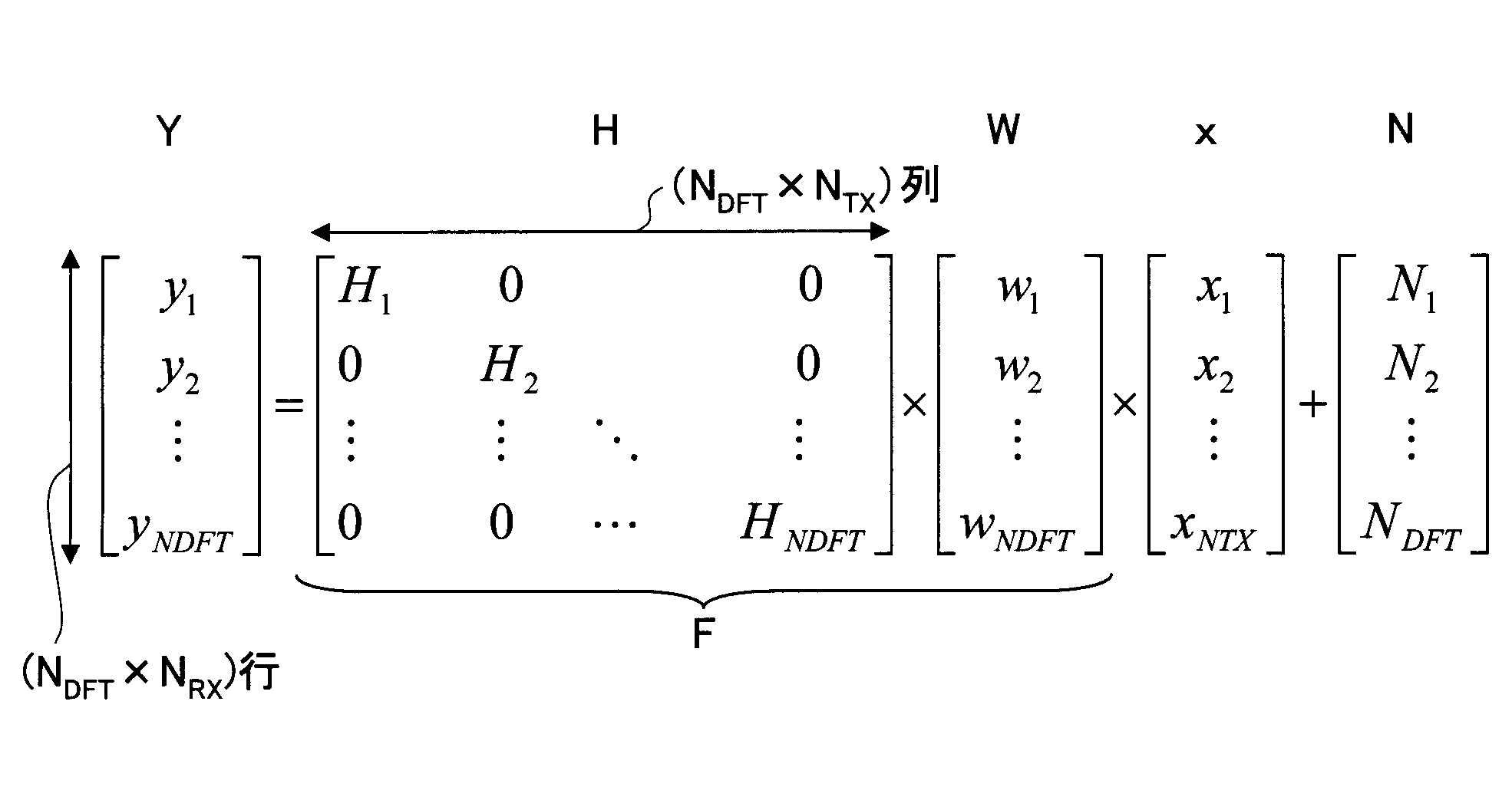
このような信号が図4の信号検出部44に入力される。
ここで、上三角行列Rは、M行M列の正方行列(M=NDFT×NTX)であって、行列要素rij(i>j)が全てゼロであるような行列である。
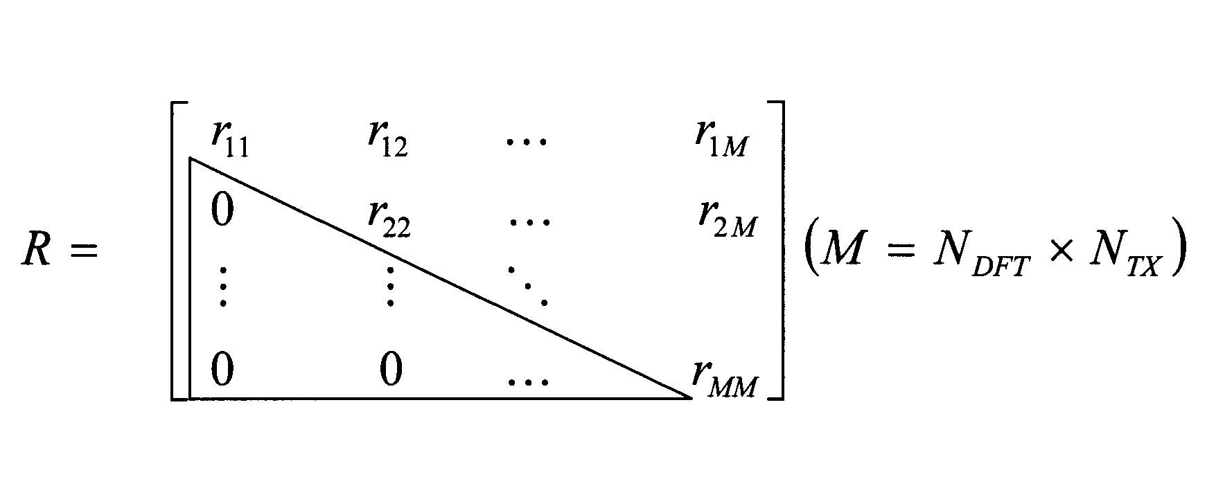
z=QHY
と書ける。右辺は、
QH×(H×W×x+N)=QH×(Q×R×x+N)=R×x+QHN ・・・(3)
と書ける。従って、ユニタリ変換後の受信信号zは、ノイズを無視すると、R×xで表現できる。
Rは上三角行列なので、M番目の信号成分に着目すると(M=NDFT×NTX)、
zM=rMM×xM ・・・(5)
と書ける。これは、M番目の信号成分xMは、他のサブキャリア及び/又は他の送信アンテナからの信号の干渉を考慮せずに、かなり簡易に推定できることを意味する。
この生き残りメトリックの内、小さい順にS1個(S1≦C)の候補が残され、他の候補は破棄される。Cはシンボルコンステレーションに含まれる信号点の総数(可能な候補総数)である。
xMについては第1ステージで導出されたS1個の候補が使用される。xM-1についても全部でC通りの候補が存在する。従って、xMとxM-1との可能な全ての組み合わせ(S1×C個)について、上記と同様な生き残りメットリックが計算される。
右辺第2項は、第1ステージで導出された生き残りメトリックの値である。この生き残りメトリックe2(sM (x),sM-1 (x))の小さい順にS2個(S2≦S1C)の候補が残され、他の候補は破棄される。
図5は、図4の信号検出部の詳細を示し、主に上記の動作説明の処理を実行する。信号検出部は、QR分解部210と、信号変換部212と、最尤判定部214と、尤度出力部215とを有する。最尤判定部214は、4つの判定部216-1,216-2,216-3,216-4を有する。図示の簡明化を図るため、判定部の数は4つしか描かれていないが、送信信号数に合わせていくつでも用意されてよい。各判定部は同様な処理ブロックを有するので、第4の判定部216-4がそれらを代表して説明される。判定部は、シンボルレプリカ生成部218-4と、二乗ユークリッド距離算出部220-4と、生き残りシンボル候補選択部222-4とを有する。
最尤判定部214は、最尤判定法(MLD法)により、送信信号のシンボル候補を絞り込む。判定部216-4のシンボルレプリカ生成部218-4は、上三角行列Rの行列要素を用いて、受信信号x4に対応する送信信号のシンボル候補を生成する。シンボル候補数は例えばC個である。
上記実施例では、F=H×WがQR分解された。しかしながら本発明はこれに限定されない。例えば、次式のような行列GがQR分解されるようにしてもよい。
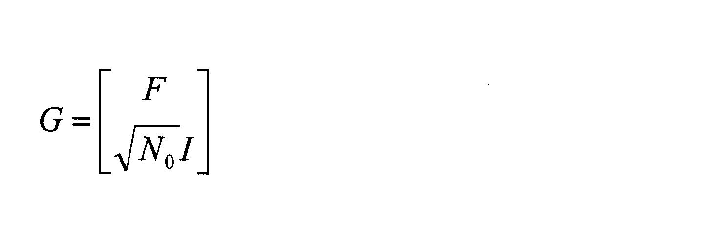

上記の動作説明で述べたように、NTX個の送信アンテナからNDFT個のサブキャリアでシンボルが送信された場合、受信信号Yは、ノイズを省略すると次のように書ける。
Hはチャネル行列である。WはDFTによる周波数方向の重み付けを表すウエイト行列である。Fはチャネル行列Hとウエイト行列Wとの行列積を表す。xは送信されるシンボルを表す。上記の動作説明では、行列積FがQR分解された。そして、Mアルゴリズムに従って、送信されたシンボルが順に推定された。Mアルゴリズムの総ステージ数は、NTX×NDFT個である。受信信号Yにユニタリ行列QHが乗算され、最下位のシンボルから順に推定が行われる。
RはNDFT×NTX行NDFT×NTX列の上三角行列である。
例えば、行列Aが2行2列の行列であり、列ベクトルsが2行1列の列ベクトルs=(s1 s2)Tであったとすると、次式が成り立つ。

行列F'は、行列F(=H×W)に含まれている列を何らかの方法で置換したものである。列ベクトルx'は、その置換方法に対応して、列ベクトルxの成分が並べ替えられた列ベクトルである。
上記の方法1(送信アンテナ単位の順序制御法)を説明する。本方法では、積行列Fの列の並べ替えは、送信されたシンボルが、受信装置でどの程度強く受信されたかに応じて決定される。Mアルゴリズムで順にシンボルを推定する際、k番目のステージ(1≦k≦NTXNSF)では、1~(k-1)番目までのステージで推定されたシンボルと、三角行列Rのk番目の行が使用される。これは、生き残りシンボルレプリカ候補の絞り込みが、k番目までに順序づけされた送信シンボルに対し、それぞれ行列Rの第(NTXNSF-k+1)列の第(NTXNSF-k+1)行からNTXNSF行までの要素の二乗和(信号電力)を用いて行われることを意味する。従って、初めの方のステージほど(特に、初段では)推定処理は簡易であるが、シンボルレプリカ候補の選択を誤ってしまう確率も高い。本方法では、各送信アンテナからの送信シンボルの受信信号電力を測定し、受信信号電力の大きい送信シンボルほど上位の優先順位で推定される。受信電力が高ければ、シンボルレプリカ候補の選択は誤りにくくなるからである。このような優先順位が実現されるように、積行列Fの列及び送信シンボルxの成分の順序が制御される。
|hi,pq|2
を全ての受信アンテナについて(p=1~NRX)合計したものは、q番目の送信アンテナからのシンボルの受信電力推定に使用可能である。例えば、NTX=NRX=2,NDFT=3であったとする。この場合、i番目のサブキャリア(i=1,2,3)に関し、次式が成り立つ。
ri2=hi,21 x1+hi,22 x2
第1の送信アンテナからのシンボルの受信電力は、
PTx1=|hi,11|2+|hi,21|2
により評価できる。同様に、第2の送信アンテナからのシンボルの受信電力は、
PTx2=|hi,12|2+|hi,22|2
により評価できる。第1の送信アンテナからのシンボルの受信電力が、第2の送信アンテナからのシンボルの受信電力より大きかったとする(PTx1>PTx2)。本方法の場合、第1の送信アンテナからのシンボルx1=(x11 x12 x13)Tは、第2の送信アンテナからのシンボルx2=(x21 x22 x23)Tよりも優先的に推定されるべきである。これを実現するため、積行列F'の列の並べ替え及び送信シンボルxの成分の並べ替えが行われる。具体的には、並べ替えられた後の送信シンボルx'は、次のように書ける。
第1の送信アンテナのシンボルを優先する観点から、シンボルx1の要素が、列ベクトルの下位に来るように、並べ替えが行われる。更に、シンボルx1の中の各サブキャリア成分x11,x12,x13がどのような順序で推定されるべきかは、この段階では一義的には決まらない。一例として、サブキャリア番号の若番順を使用されてもよい。この場合、並べ替えられた後の送信シンボルx'は、次のように書ける。
若番順だけでなく、他の順序が使用されてもよい。
上記の方法2(サブキャリア単位の順序制御法)を説明する。Mアルゴリズムで生き残りシンボルレプリカ候補が選択される場合、フェージング相関の大きいシンボルの組み合わせは、大きな誤差を導入する傾向がある。フェージング相関が大きいとは、シンボルが同様なフェージングを受けていることを意味する。逆に、フェージング相関が小さいとは、シンボルが異なるフェージングを受けていることを意味する。必須ではないが、フェージング相関の値は0以上1以下の値をとり、フェージング相関は、1に近いほど大きく、0に近いほど小さい。
ri2=hi,21 x1+hi,22 x2。
この例では、サブキャリア成分に関する推定の順序は、若番順である。このことは必須ではない。若番順以外の順序がが使用されてもよい。例えば、サブキャリア成分同士の受信電力が比較され、電力の高い順番が併用されてもよい。例えば、第2、第3及び第1のサブキャリア成分の順番で、受信電力が高かったとする。変形例2の方法1で説明したように、推定精度を向上させる観点からは、受信電力の高い順に、並べ替えを行うことが望ましい。従って、この場合に望ましい並べ替え後の送信シンボルx'は、次のように書ける。
上記のアンテナ数やサブキャリア数の数値は単なる一例に過ぎず、より多くの値が使用されてもよい。
Claims (8)
- シングルキャリア方式のMIMO伝送方式が使用される移動通信システムで使用される受信装置であって、
送信されるシンボル系列中の一群のシンボルは、フーリエ変換により所定のウエイトと共に複数のサブキャリアにマッピングされた後に逆フーリエ変換され、複数の送信アンテナから送信され、当該受信装置は、
複数の受信アンテナで受信した信号をフーリエ変換し、各サブキャリアの信号成分を抽出する手段と、
抽出された信号成分にQR分解アルゴリズムを適用し、各サブキャリアのシンボルを推定する信号検出手段と、
を有し、前記信号検出手段は、
前記送信するシンボル系列とサブキャリアとの対応関係を決めるウエイト行列と、前記送信及び受信アンテナ間の無線チャネル状態を表すチャネル行列と、あるユニタリ行列との積が三角行列になるように該ユニタリ行列を求める分解手段と、
各受信アンテナで受信した信号成分を含む受信ベクトルに前記ユニタリ行列を乗算したベクトルと、前記三角行列とを用いて、各送信アンテナから送信されたシンボルの候補を推定する推定手段と、
を有する受信装置。 - 前記信号検出手段が、メトリックを前記シンボルの候補毎に用意し、前記メトリックに応じて候補を絞り込む手段を更に有し、前記メトリックは、シンボルコンステレーションにおける受信シンボル及びシンボルの候補間の二乗ユークリッド距離を表す
ようにした請求項1記載の受信装置。 - 前記チャネル行列及び前記ウエイト行列の行列積の行又は列を並べ替えるための指示信号を、前記分解手段に与える並替制御手段が、当該受信装置に設けられ、
前記分解手段は、前記指示信号に従って、行又は列の並べ替えられた前記行列積が、三角行列及びユニタリ行列の積に等しくなるように、該三角行列及び該ユニタリ行列を求める
ようにした請求項1記載の受信装置。 - 前記推定手段が、Mアルゴリズムに従ってシンボルを推定する際、より強い受信電力に対応する送信アンテナのシンボルが、より弱い受信電力に対応する送信アンテナのシンボルよりも先に推定されるように、前記並替制御手段は前記指示信号を用意する
ようにした請求項3記載の受信装置。 - 第1の送信アンテナから送信されたシンボルの第1のサブキャリアのサブキャリア成分が、前記推定手段で推定された後に、
該第1のサブキャリアで第2の送信アンテナから送信されたシンボルのサブキャリア成分が、前記推定手段で推定されるように、
前記並替制御手段は前記指示信号を用意する
ようにした請求項3記載の受信装置。 - シングルキャリア方式のMIMO伝送方式が使用され、送信装置及び受信装置を含む移動通信システムであって、前記送信装置は、
送信するシンボル系列中の一群のシンボルを、フーリエ変換により、所定のウエイトと共に複数のサブキャリアにマッピングする手段と、
マッピングされた一群のシンボルを逆フーリエ変換する手段と、
逆フーリエ変換後のシンボルを含む信号を複数の送信アンテナから送信する手段と、
を有し、前記受信装置は、
複数の受信アンテナで受信した信号をフーリエ変換し、各サブキャリアにマッピングされている信号成分を抽出する手段と、
抽出された信号成分にQR分解アルゴリズムを適用し、各サブキャリアで伝送されたシンボルを推定する信号検出手段と、
を有し、前記信号検出手段は、
前記送信するシンボル系列とサブキャリアとの対応関係を決める行列と、前記送信及び受信アンテナ間の無線チャネル状態を表すチャネル行列と、あるユニタリ行列との積が三角行列になるように該ユニタリ行列を導出する分解手段と、
各受信アンテナで受信した信号成分を含む受信ベクトルに前記ユニタリ行列を乗算したベクトルと、前記三角行列とを用いて、各送信アンテナから送信されたシンボルの候補を推定する推定手段と、
を有する移動通信システム。 - 前記送信装置がユーザ装置に備わり、前記受信装置が基地局装置に備わるようにした請求項6記載の移動通信システム。
- シングルキャリア方式のMIMO伝送方式が使用され、送信装置及び受信装置を含む移動通信システムで使用される方法であって、
送信するシンボル系列中の一群のシンボルを、フーリエ変換により、所定のウエイトと共に複数のサブキャリアにマッピングするステップと、
マッピングされた一群のシンボルを逆フーリエ変換するステップと、
逆フーリエ変換後のシンボルを含む信号を複数の送信アンテナから送信するステップと、
が前記送信装置で行われ、
複数の受信アンテナで受信した信号をフーリエ変換し、各サブキャリアの信号成分を抽出するステップと、
抽出された信号成分にQR分解アルゴリズムを適用し、各サブキャリアのシンボルを推定する信号検出ステップと、
が前記受信装置で行われ、前記信号検出ステップでは、
前記送信するシンボル系列とサブキャリアとの対応関係を決める行列と、前記送信及び受信アンテナ間の無線チャネル状態を表すチャネル行列と、あるユニタリ行列との積が三角行列になるように該ユニタリ行列が導出され、
各受信アンテナで受信した信号成分を含む受信ベクトルに前記ユニタリ行列を乗算したベクトルと、前記三角行列とを用いて、各送信アンテナから送信されたシンボルの候補が推定されるようにした方法。
Priority Applications (5)
| Application Number | Priority Date | Filing Date | Title |
|---|---|---|---|
| US12/864,888 US8320507B2 (en) | 2008-02-04 | 2009-01-30 | Mobile communication system, receiving device, and method |
| BRPI0906353-6A BRPI0906353A2 (pt) | 2008-02-04 | 2009-01-30 | Sistema de comunicação móvel, dispositivo de recepção e método |
| EP09707309.2A EP2242197A4 (en) | 2008-02-04 | 2009-01-30 | MOBILE COMMUNICATION SYSTEM, RECEIVER AND METHOD THEREFOR |
| CN2009801116820A CN101981847B (zh) | 2008-02-04 | 2009-01-30 | 移动通信系统、接收装置以及方法 |
| RU2010135412/07A RU2481712C2 (ru) | 2008-02-04 | 2009-01-30 | Система мобильной связи, приемное устройство и способ передачи сигнала |
Applications Claiming Priority (4)
| Application Number | Priority Date | Filing Date | Title |
|---|---|---|---|
| JP2008-024355 | 2008-02-04 | ||
| JP2008024355 | 2008-02-04 | ||
| JP2008315035A JP5122428B2 (ja) | 2008-02-04 | 2008-12-10 | 移動通信システム、受信装置及び方法 |
| JP2008-315035 | 2008-12-10 |
Publications (1)
| Publication Number | Publication Date |
|---|---|
| WO2009099013A1 true WO2009099013A1 (ja) | 2009-08-13 |
Family
ID=40952088
Family Applications (1)
| Application Number | Title | Priority Date | Filing Date |
|---|---|---|---|
| PCT/JP2009/051626 Ceased WO2009099013A1 (ja) | 2008-02-04 | 2009-01-30 | 移動通信システム、受信装置及び方法 |
Country Status (8)
| Country | Link |
|---|---|
| US (1) | US8320507B2 (ja) |
| EP (1) | EP2242197A4 (ja) |
| JP (1) | JP5122428B2 (ja) |
| KR (1) | KR20100122478A (ja) |
| CN (1) | CN101981847B (ja) |
| BR (1) | BRPI0906353A2 (ja) |
| RU (1) | RU2481712C2 (ja) |
| WO (1) | WO2009099013A1 (ja) |
Cited By (2)
| Publication number | Priority date | Publication date | Assignee | Title |
|---|---|---|---|---|
| CN114270720A (zh) * | 2019-07-01 | 2022-04-01 | 拉姆帕特通信股份有限公司 | 使用任意酉矩阵的分层构造的通信系统和方法 |
| US12184364B2 (en) | 2019-09-24 | 2024-12-31 | Rampart Communications, Inc. | Communication system and methods using very large multiple-in multiple-out (MIMO) antenna systems with extremely large class of fast unitary transformations |
Families Citing this family (24)
| Publication number | Priority date | Publication date | Assignee | Title |
|---|---|---|---|---|
| US8199841B1 (en) | 2007-04-26 | 2012-06-12 | Marvell International Ltd. | Channel tracking in a wireless multiple-input multiple-output (MIMO) communication system |
| JP5074148B2 (ja) * | 2007-10-19 | 2012-11-14 | 株式会社日立国際電気 | 最尤復号化方法、最尤復号装置、及び受信機 |
| KR20110007157A (ko) * | 2008-04-04 | 2011-01-21 | 가부시키가이샤 엔티티 도코모 | 이동통신시스템, 수신장치 및 방법 |
| JP5576168B2 (ja) * | 2010-04-09 | 2014-08-20 | 株式会社Nttドコモ | 無線受信装置及び無線受信方法 |
| CN102255642B (zh) * | 2010-05-19 | 2014-01-01 | 华为技术有限公司 | 一种干扰消除方法及设备、系统 |
| EP2541679A1 (en) * | 2011-06-30 | 2013-01-02 | Sony Corporation | Wideband beam forming device, wideband beam steering device and corresponding methods |
| US8693561B2 (en) | 2012-03-16 | 2014-04-08 | Posedge Inc. | Receive signal detection of multi-carrier signals |
| US9106470B2 (en) | 2012-12-03 | 2015-08-11 | Qualcomm Incorporated | Enhanced decoding and demapping method and apparatus for QAM data signals |
| KR20150127480A (ko) * | 2014-05-07 | 2015-11-17 | 한국전자통신연구원 | 부분 ml을 근거로 한 신호 검출 시스템 및 그 방법 |
| WO2016090557A1 (zh) * | 2014-12-09 | 2016-06-16 | 华为技术有限公司 | 一种检测发送序列的方法、接收机和接收设备 |
| US10110346B1 (en) * | 2016-04-14 | 2018-10-23 | Mbit Wireless, Inc. | Method and apparatus for soft bit computation in MIMO decoders |
| US10020839B2 (en) | 2016-11-14 | 2018-07-10 | Rampart Communications, LLC | Reliable orthogonal spreading codes in wireless communications |
| EP3557923A4 (en) * | 2016-12-19 | 2020-07-22 | Ntt Docomo, Inc. | USER TERMINAL |
| WO2018116777A1 (ja) * | 2016-12-19 | 2018-06-28 | 株式会社Nttドコモ | ユーザ端末 |
| CN106911374B (zh) * | 2017-01-16 | 2020-08-04 | 重庆邮电大学 | 一种低复杂度软输出空间调制检测方法 |
| CN109995463A (zh) | 2017-12-29 | 2019-07-09 | 深圳超级数据链技术有限公司 | 一种qr分解检测方法和装置 |
| US10873361B2 (en) | 2019-05-17 | 2020-12-22 | Rampart Communications, Inc. | Communication system and methods using multiple-in-multiple-out (MIMO) antennas within unitary braid divisional multiplexing (UBDM) |
| US11025470B2 (en) | 2019-07-01 | 2021-06-01 | Rampart Communications, Inc. | Communication system and method using orthogonal frequency division multiplexing (OFDM) with non-linear transformation |
| US11050604B2 (en) | 2019-07-01 | 2021-06-29 | Rampart Communications, Inc. | Systems, methods and apparatuses for modulation-agnostic unitary braid division multiplexing signal transformation |
| US10917148B2 (en) | 2019-07-01 | 2021-02-09 | Rampart Communications, Inc. | Systems, methods and apparatus for secure and efficient wireless communication of signals using a generalized approach within unitary braid division multiplexing |
| US11641269B2 (en) | 2020-06-30 | 2023-05-02 | Rampart Communications, Inc. | Modulation-agnostic transformations using unitary braid divisional multiplexing (UBDM) |
| US10951442B2 (en) | 2019-07-31 | 2021-03-16 | Rampart Communications, Inc. | Communication system and method using unitary braid divisional multiplexing (UBDM) with physical layer security |
| US10735062B1 (en) | 2019-09-04 | 2020-08-04 | Rampart Communications, Inc. | Communication system and method for achieving high data rates using modified nearly-equiangular tight frame (NETF) matrices |
| US11159220B2 (en) | 2020-02-11 | 2021-10-26 | Rampart Communications, Inc. | Single input single output (SISO) physical layer key exchange |
Citations (1)
| Publication number | Priority date | Publication date | Assignee | Title |
|---|---|---|---|---|
| JP2006222743A (ja) * | 2005-02-10 | 2006-08-24 | Nippon Telegr & Teleph Corp <Ntt> | 空間多重信号検出回路 |
Family Cites Families (16)
| Publication number | Priority date | Publication date | Assignee | Title |
|---|---|---|---|---|
| US6785341B2 (en) * | 2001-05-11 | 2004-08-31 | Qualcomm Incorporated | Method and apparatus for processing data in a multiple-input multiple-output (MIMO) communication system utilizing channel state information |
| US7280625B2 (en) * | 2002-12-11 | 2007-10-09 | Qualcomm Incorporated | Derivation of eigenvectors for spatial processing in MIMO communication systems |
| WO2006051156A1 (en) * | 2004-11-12 | 2006-05-18 | Nokia Corporation | Low density parity check codes for mimo systems |
| JP4290660B2 (ja) * | 2005-02-14 | 2009-07-08 | 日本電信電話株式会社 | 空間多重信号検出回路及び空間多重信号検出方法 |
| US7602855B2 (en) * | 2005-04-01 | 2009-10-13 | Interdigital Technology Corporation | Method and apparatus for singular value decomposition of a channel matrix |
| JP4666150B2 (ja) * | 2005-05-31 | 2011-04-06 | 日本電気株式会社 | Mimo受信装置、受信方法、および無線通信システム |
| US20060285531A1 (en) * | 2005-06-16 | 2006-12-21 | Howard Steven J | Efficient filter weight computation for a MIMO system |
| US7933353B2 (en) * | 2005-09-30 | 2011-04-26 | Intel Corporation | Communication system and technique using QR decomposition with a triangular systolic array |
| CN101467407B (zh) * | 2006-04-27 | 2016-05-04 | 意大利电信股份公司 | 单一载波频分多址系统中的频域信道估计 |
| JP4854378B2 (ja) * | 2006-05-01 | 2012-01-18 | ソフトバンクBb株式会社 | 無線伝送システムおよび無線伝送方法 |
| KR101382760B1 (ko) * | 2007-03-21 | 2014-04-08 | 엘지전자 주식회사 | 다중 안테나를 이용한 통신시스템에서 코드북을 이용한데이터 전송방법 |
| US8199841B1 (en) * | 2007-04-26 | 2012-06-12 | Marvell International Ltd. | Channel tracking in a wireless multiple-input multiple-output (MIMO) communication system |
| KR100965728B1 (ko) * | 2007-06-12 | 2010-06-24 | 삼성전자주식회사 | 최대 우도 방식을 사용한 신호 검출 장치 및 방법 |
| GB2453776B (en) * | 2007-10-18 | 2010-05-19 | Toshiba Res Europ Ltd | Wireless communications apparatus |
| KR100934007B1 (ko) * | 2007-12-18 | 2009-12-28 | 한국전자통신연구원 | 다중입력 다중출력 수신기에서 다차원 검출 장치 및방법과, 이를 이용한 수신 장치 |
| US8411781B2 (en) * | 2009-06-11 | 2013-04-02 | Mediatek Inc. | Method and system for operating a MIMO decoder |
-
2008
- 2008-12-10 JP JP2008315035A patent/JP5122428B2/ja not_active Expired - Fee Related
-
2009
- 2009-01-30 CN CN2009801116820A patent/CN101981847B/zh not_active Expired - Fee Related
- 2009-01-30 WO PCT/JP2009/051626 patent/WO2009099013A1/ja not_active Ceased
- 2009-01-30 RU RU2010135412/07A patent/RU2481712C2/ru not_active IP Right Cessation
- 2009-01-30 KR KR1020107017038A patent/KR20100122478A/ko not_active Ceased
- 2009-01-30 US US12/864,888 patent/US8320507B2/en not_active Expired - Fee Related
- 2009-01-30 EP EP09707309.2A patent/EP2242197A4/en not_active Withdrawn
- 2009-01-30 BR BRPI0906353-6A patent/BRPI0906353A2/pt not_active IP Right Cessation
Patent Citations (1)
| Publication number | Priority date | Publication date | Assignee | Title |
|---|---|---|---|---|
| JP2006222743A (ja) * | 2005-02-10 | 2006-08-24 | Nippon Telegr & Teleph Corp <Ntt> | 空間多重信号検出回路 |
Non-Patent Citations (5)
Cited By (3)
| Publication number | Priority date | Publication date | Assignee | Title |
|---|---|---|---|---|
| CN114270720A (zh) * | 2019-07-01 | 2022-04-01 | 拉姆帕特通信股份有限公司 | 使用任意酉矩阵的分层构造的通信系统和方法 |
| CN114270720B (zh) * | 2019-07-01 | 2024-05-03 | 拉姆帕特通信股份有限公司 | 使用任意酉矩阵的分层构造的通信系统和方法 |
| US12184364B2 (en) | 2019-09-24 | 2024-12-31 | Rampart Communications, Inc. | Communication system and methods using very large multiple-in multiple-out (MIMO) antenna systems with extremely large class of fast unitary transformations |
Also Published As
| Publication number | Publication date |
|---|---|
| EP2242197A1 (en) | 2010-10-20 |
| JP5122428B2 (ja) | 2013-01-16 |
| RU2010135412A (ru) | 2012-03-20 |
| US8320507B2 (en) | 2012-11-27 |
| CN101981847B (zh) | 2013-12-25 |
| BRPI0906353A2 (pt) | 2015-07-07 |
| CN101981847A (zh) | 2011-02-23 |
| RU2481712C2 (ru) | 2013-05-10 |
| US20100329393A1 (en) | 2010-12-30 |
| JP2009213124A (ja) | 2009-09-17 |
| EP2242197A4 (en) | 2016-05-11 |
| KR20100122478A (ko) | 2010-11-22 |
Similar Documents
| Publication | Publication Date | Title |
|---|---|---|
| JP5122428B2 (ja) | 移動通信システム、受信装置及び方法 | |
| JP5345133B2 (ja) | 移動通信システム、受信装置及び方法 | |
| US11894965B2 (en) | Efficient synthesis and analysis of OFDM and MIMO-OFDM signals | |
| US11196603B2 (en) | Efficient synthesis and analysis of OFDM and MIMO-OFDM signals | |
| US9008166B2 (en) | Filter calculating device, transmitting device, receiving device, processor, and filter calculating method | |
| EP2582078B1 (en) | Mimo receiving device and receiving method | |
| US9100259B2 (en) | Receiving device, receiving method, and receiving program | |
| CN101512996B (zh) | 均衡结构与均衡方法 | |
| WO2015186531A1 (ja) | 端末装置、フィードバック情報生成方法、及び基地局装置 | |
| CN102685060B (zh) | 一种正交频分复用系统中多用户mimo接收方法和装置 | |
| EP2391047A2 (en) | Method for estimating a received signal and corresponding device | |
| US8363756B2 (en) | Wireless reception device, wireless communication system and wireless communication method | |
| Bhoyar et al. | Leaky least mean square (LLMS) algorithm for channel estimation in BPSK-QPSK-PSK MIMO-OFDM system | |
| CN101507213B (zh) | 均衡结构与均衡方法 | |
| JP5770558B2 (ja) | 受信装置、プログラムおよび集積回路 | |
| CN101719816A (zh) | 实现自适应mimo-scfde系统低反馈速率的方法 | |
| CN101507214A (zh) | 均衡结构与均衡方法 | |
| KR101271288B1 (ko) | 무선 통신 시스템에서의 데이터 전송장치 및 방법 | |
| WO2012064173A1 (en) | A method of detecting signals |
Legal Events
| Date | Code | Title | Description |
|---|---|---|---|
| WWE | Wipo information: entry into national phase |
Ref document number: 200980111682.0 Country of ref document: CN |
|
| 121 | Ep: the epo has been informed by wipo that ep was designated in this application |
Ref document number: 09707309 Country of ref document: EP Kind code of ref document: A1 |
|
| WWE | Wipo information: entry into national phase |
Ref document number: 2559/KOLNP/2010 Country of ref document: IN |
|
| ENP | Entry into the national phase |
Ref document number: 20107017038 Country of ref document: KR Kind code of ref document: A |
|
| NENP | Non-entry into the national phase |
Ref country code: DE |
|
| REEP | Request for entry into the european phase |
Ref document number: 2009707309 Country of ref document: EP |
|
| WWE | Wipo information: entry into national phase |
Ref document number: 2009707309 Country of ref document: EP |
|
| WWE | Wipo information: entry into national phase |
Ref document number: 12864888 Country of ref document: US |
|
| WWE | Wipo information: entry into national phase |
Ref document number: 2010135412 Country of ref document: RU |
|
| ENP | Entry into the national phase |
Ref document number: PI0906353 Country of ref document: BR Kind code of ref document: A2 Effective date: 20100729 |