WO2009101882A1 - X線発生装置、x線撮影装置及びそれらの制御方法 - Google Patents
X線発生装置、x線撮影装置及びそれらの制御方法 Download PDFInfo
- Publication number
- WO2009101882A1 WO2009101882A1 PCT/JP2009/051853 JP2009051853W WO2009101882A1 WO 2009101882 A1 WO2009101882 A1 WO 2009101882A1 JP 2009051853 W JP2009051853 W JP 2009051853W WO 2009101882 A1 WO2009101882 A1 WO 2009101882A1
- Authority
- WO
- WIPO (PCT)
- Prior art keywords
- ray
- electron
- electron beam
- target electrode
- generating
- Prior art date
- Legal status (The legal status is an assumption and is not a legal conclusion. Google has not performed a legal analysis and makes no representation as to the accuracy of the status listed.)
- Ceased
Links
Images




Classifications
-
- H—ELECTRICITY
- H01—ELECTRIC ELEMENTS
- H01J—ELECTRIC DISCHARGE TUBES OR DISCHARGE LAMPS
- H01J35/00—X-ray tubes
- H01J35/02—Details
- H01J35/04—Electrodes ; Mutual position thereof; Constructional adaptations therefor
- H01J35/06—Cathodes
- H01J35/066—Details of electron optical components, e.g. cathode cups
-
- H—ELECTRICITY
- H01—ELECTRIC ELEMENTS
- H01J—ELECTRIC DISCHARGE TUBES OR DISCHARGE LAMPS
- H01J35/00—X-ray tubes
- H01J35/02—Details
- H01J35/14—Arrangements for concentrating, focusing, or directing the cathode ray
- H01J35/147—Spot size control
-
- A—HUMAN NECESSITIES
- A61—MEDICAL OR VETERINARY SCIENCE; HYGIENE
- A61B—DIAGNOSIS; SURGERY; IDENTIFICATION
- A61B6/00—Apparatus or devices for radiation diagnosis; Apparatus or devices for radiation diagnosis combined with radiation therapy equipment
- A61B6/40—Arrangements for generating radiation specially adapted for radiation diagnosis
- A61B6/4021—Arrangements for generating radiation specially adapted for radiation diagnosis involving movement of the focal spot
-
- A—HUMAN NECESSITIES
- A61—MEDICAL OR VETERINARY SCIENCE; HYGIENE
- A61B—DIAGNOSIS; SURGERY; IDENTIFICATION
- A61B6/00—Apparatus or devices for radiation diagnosis; Apparatus or devices for radiation diagnosis combined with radiation therapy equipment
- A61B6/40—Arrangements for generating radiation specially adapted for radiation diagnosis
- A61B6/405—Source units specially adapted to modify characteristics of the beam during the data acquisition process
-
- A—HUMAN NECESSITIES
- A61—MEDICAL OR VETERINARY SCIENCE; HYGIENE
- A61B—DIAGNOSIS; SURGERY; IDENTIFICATION
- A61B6/00—Apparatus or devices for radiation diagnosis; Apparatus or devices for radiation diagnosis combined with radiation therapy equipment
- A61B6/44—Constructional features of apparatus for radiation diagnosis
- A61B6/4405—Constructional features of apparatus for radiation diagnosis the apparatus being movable or portable, e.g. handheld or mounted on a trolley
-
- A—HUMAN NECESSITIES
- A61—MEDICAL OR VETERINARY SCIENCE; HYGIENE
- A61B—DIAGNOSIS; SURGERY; IDENTIFICATION
- A61B6/00—Apparatus or devices for radiation diagnosis; Apparatus or devices for radiation diagnosis combined with radiation therapy equipment
- A61B6/44—Constructional features of apparatus for radiation diagnosis
- A61B6/4429—Constructional features of apparatus for radiation diagnosis related to the mounting of source units and detector units
- A61B6/4435—Constructional features of apparatus for radiation diagnosis related to the mounting of source units and detector units the source unit and the detector unit being coupled by a rigid structure
- A61B6/4441—Constructional features of apparatus for radiation diagnosis related to the mounting of source units and detector units the source unit and the detector unit being coupled by a rigid structure the rigid structure being a C-arm or U-arm
-
- A—HUMAN NECESSITIES
- A61—MEDICAL OR VETERINARY SCIENCE; HYGIENE
- A61B—DIAGNOSIS; SURGERY; IDENTIFICATION
- A61B6/00—Apparatus or devices for radiation diagnosis; Apparatus or devices for radiation diagnosis combined with radiation therapy equipment
- A61B6/46—Arrangements for interfacing with the operator or the patient
- A61B6/467—Arrangements for interfacing with the operator or the patient characterised by special input means
- A61B6/469—Arrangements for interfacing with the operator or the patient characterised by special input means for selecting a region of interest [ROI]
-
- A—HUMAN NECESSITIES
- A61—MEDICAL OR VETERINARY SCIENCE; HYGIENE
- A61B—DIAGNOSIS; SURGERY; IDENTIFICATION
- A61B6/00—Apparatus or devices for radiation diagnosis; Apparatus or devices for radiation diagnosis combined with radiation therapy equipment
- A61B6/54—Control of apparatus or devices for radiation diagnosis
- A61B6/542—Control of apparatus or devices for radiation diagnosis involving control of exposure
-
- H—ELECTRICITY
- H01—ELECTRIC ELEMENTS
- H01J—ELECTRIC DISCHARGE TUBES OR DISCHARGE LAMPS
- H01J35/00—X-ray tubes
- H01J35/02—Details
- H01J35/04—Electrodes ; Mutual position thereof; Constructional adaptations therefor
- H01J35/06—Cathodes
- H01J35/065—Field emission, photo emission or secondary emission cathodes
-
- H—ELECTRICITY
- H01—ELECTRIC ELEMENTS
- H01J—ELECTRIC DISCHARGE TUBES OR DISCHARGE LAMPS
- H01J2235/00—X-ray tubes
- H01J2235/06—Cathode assembly
- H01J2235/062—Cold cathodes
-
- H—ELECTRICITY
- H01—ELECTRIC ELEMENTS
- H01J—ELECTRIC DISCHARGE TUBES OR DISCHARGE LAMPS
- H01J2235/00—X-ray tubes
- H01J2235/06—Cathode assembly
- H01J2235/068—Multi-cathode assembly
Definitions
- the present invention relates to an X-ray generator used for non-destructive X-ray imaging in the field of medical diagnostic equipment and industrial equipment using an X-ray source, and an X-ray imaging apparatus using the apparatus.
- thermoelectron source in an X-ray tube, a thermoelectron source is used as an electron source, and thermoelectrons emitted from a filament heated to a high temperature are accelerated and focused to form a desired electron beam, which is formed of a metal X-ray. X-rays are generated by irradiating the target.
- the generation efficiency of X-rays is known to be extremely low, and most of the energy of the electron beam irradiated to the target is changed to heat. Therefore, in the X-ray generator, a structure of a rotating anode that rotates a target has been conventionally used.
- the size of the X-ray focal point formed on the target is preferably small.
- the size of the X-ray focal point is reduced while securing the current, there is a problem of the above-mentioned heat generation due to the heat load being concentrated on a small area, while on the other hand, there is a problem that the sharpness is lowered.
- An object of the present invention is to provide an X-ray generator and an X-ray imaging apparatus that achieve a large current in X-ray generation without reducing the sharpness of an image.
- an X-ray generator comprises the following arrangement. That is, An electron beam generating means having a plurality of electron emitting elements and generating an electron beam corresponding to the driven electron emitting elements; A target electrode for generating X-rays with an irradiation position of the electron beam generated by the electron beam generating means as an X-ray focal point; Drive control means for controlling the X-ray focal point shape formed by the set of X-ray focal points in the target electrode by individually controlling the driving of the plurality of electron-emitting devices.
- an X-ray imaging apparatus for achieving the above object has the following configuration. That is, An electron beam generating means having a plurality of electron emitting elements and generating an electron beam corresponding to the driven electron emitting elements; A target electrode for generating X-rays with an irradiation position of the electron beam generated by the electron beam generating means as an X-ray focal point; Drive control means for controlling an X-ray focal point shape formed by a set of X-ray focal points in the target electrode by individually controlling driving of the plurality of electron-emitting devices; Detecting means for generating a two-dimensional X-ray image by detecting X-rays generated from the target electrode; Determination means for determining, based on the two-dimensional X-ray image detected by the detection means, the X-ray focus shape to be formed on the target electrode by the drive control means.
- an X-ray generator and an X-ray imaging apparatus that achieve a large current in X-ray generation without reducing the sharpness of an image.
- FIG. 1 is a block diagram illustrating a basic configuration example of an X-ray imaging apparatus according to an embodiment. It is a figure which shows the specific example of the X-ray imaging apparatus by embodiment. It is a block diagram which shows the basic structural example of the X-ray generator in the X-ray imaging apparatus shown in FIG. It is a figure explaining the drive pattern of an electron-emitting device, and the shape of a X-ray focus. It is a block diagram which shows the structural example of the main direction determination part in the X-ray imaging apparatus shown in FIG. It is a figure explaining the process of the frequency analysis in a main direction determination part. It is a block diagram which shows the structural example of the image process part in the X-ray imaging apparatus shown in FIG. It is a flowchart explaining the X-ray imaging process by 1st Embodiment. It is a figure which shows the modification of the arrangement
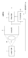
- FIG. 1 is a diagram showing a configuration of an X-ray imaging apparatus according to the first embodiment.
- X-ray XR irradiated from the X-ray generator 1 passes through the subject P and enters the X-ray detector 2.
- the X-ray detector 2 is a flat detector for an X-ray image, and outputs the X-ray intensity distribution attenuated through the subject P as an image to the main direction determination unit 3 and the image processing unit 4.
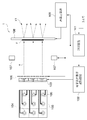
- FIG. 2 is a diagram showing an example of this, and an X-ray fluoroscopic imaging apparatus that captures a fluoroscopic image of a patient who is a subject P using an X-ray generator 1 and an X-ray detector 2 attached to a C-shaped arm 21. Is shown.
- the main direction determination unit 3 and the image processing unit 4 are realized by a computer and software (not shown) housed in the control device 22 surrounded by a broken line.
- the main direction determining unit 3 analyzes an image input from the X-ray detector 2 to determine a main direction (details will be described later), and on the target electrode in the X-ray generator 1 based on the result. To control the shape of the X-ray focal point generated. Note that the image processing unit 4 is not used in the first embodiment. The image processing unit 4 will be described in the third embodiment.
- the control circuit 101 individually drives a plurality of electron-emitting devices 104 arranged on the element substrate 103 via the electrodes 105 based on the conditions input from the main direction determination unit 3. Electrons emitted from the electron-emitting device 104 are formed into an electron beam e by the extraction electrode 106 and the lens electrode 107. As described above, the element substrate 103 having the plurality of electron-emitting devices 104 that can be individually driven, the extraction electrode 106, and the lens electrode 107 generate an electron beam corresponding to the driven electron-emitting device. Parts.
- the electron beam e is irradiated onto the target electrode 108 connected to the high voltage power source 109 to form an X-ray focal point F.
- X-rays XR are emitted from the X-ray focal point F formed on the target electrode 108 in the direction opposite to the electron beam e.
- the target electrode 108 generates X-rays having an X-ray focal point as the irradiation position of the electron beam generated by the electron beam generator described above.
- the electrons emitted from the electron emission portion composed of the plurality of electron-emitting devices 104 are directed toward the target electrode 108 by the extraction electrode 106, the lens electrode 107, and the target electrode 108 to which a high voltage is applied. Accelerated.
- the target electrode 108 also functions as an X-ray generator that generates X-rays when the accelerated electrons collide.
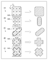
- FIG. 4 is a diagram illustrating the drive pattern of the electron-emitting device 104 on the element substrate 103 and the shape of the X-ray focal point formed on the target electrode 108 correspondingly.
- FIGS. 4A to 4E when the electron-emitting device 104 surrounded by the thick broken line in the element substrate 103 shown on the left side is driven, the X-ray focal point having the shape shown on the right side is formed on the target electrode. Is shown.
- control circuit 101 and the electron-emitting device driving circuit 102 individually control the driving of the plurality of electron-emitting devices 104, thereby forming the shape of the X-ray focal point formed by the set of X-ray focal points on the target electrode ( Hereinafter, the X-ray focal point shape is also controlled.
- the change of the shape of the X-ray focal point can be realized by turning on or off the electrode 105 of the electron-emitting device 104 as shown in FIG.
- the size may be changed by adjusting the focusing of the electron beam by the lens electrode 107.
- the electron-emitting devices are arranged in 3 ⁇ 3.
- the number and arrangement of the electron-emitting devices are not limited to this, and the shape of the X-ray focal point formed on the target electrode 108 is also limited. It is not restricted to the thing of illustration.
- the electron-emitting devices can be arranged radially as shown in FIG.
- the intervals between the electron-emitting devices are equal to each other in the radial direction from the center of the image. Therefore, for example, in the patterns 4B and 4C in FIG. 4, it is possible to easily match the electron beam intensity distribution in the same diameter direction.
- the X-ray detector 2 is a flat detector that detects X-rays transmitted through the subject P, converts them into digital signals, and outputs an X-ray image.
- the X-ray detector 2 has X-ray detection elements arranged in a matrix.
- As a method for converting an X-ray into an electric signal either an indirect type in which the X-ray is once converted into an optical signal and then converted into an electric signal, or a direct type in which the X-ray is directly converted into an electric signal is used. It is applicable to the embodiment.
- the X-ray detector 2 is not limited to the flat detector as described above.
- any device can be used as long as it outputs an X-ray image generated by transmitting through a subject as a digital signal, such as an image intensifier or CR (Computed Radiography).
- FIG. 5 is a block diagram illustrating a configuration example of the main direction determination unit 3.
- the main direction determination unit 3 can be realized by computer software, dedicated hardware, or a combination thereof.
- the X-ray image output from the X-ray detector 2 is subjected to frequency analysis along a plurality of directions by the frequency analysis unit 301.
- the operation of the frequency analysis unit 301 will be exemplified below with reference to FIG.
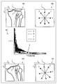
- the frequency analysis unit 301 inputs, for example, an image (X-ray image) as shown in 6A of FIG. 6 and samples image data along four radial directions A to D shown by 6A of FIG. Then, four data strings are extracted. Further, a frequency spectrum is calculated by Fourier transform for each of the data strings. 6C of FIG. 6 shows an example of the calculated frequency spectrum.
- the frequency analysis unit 301 thus calculates the frequency power for the data sequence corresponding to each of the directions A to D, and outputs it to the main direction analysis unit 302 as frequency power data.
- the main direction analysis unit 302 Based on the frequency power data from the frequency analysis unit 301, the main direction analysis unit 302 analyzes which of A to D the main direction of the subject in the image corresponds to. In this embodiment, the main direction analysis unit 302 determines the main direction ⁇ based on the following equation when the frequency power data input from the frequency analysis unit 301 is p d and d ⁇ ⁇ A, B, C, D ⁇ . To do.
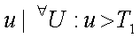
- the main direction ⁇ is the direction in which the area occupied by the frequency spectrum excluding low frequency components below a predetermined threshold T 1 in the spatial frequency band U obtained by frequency decomposition is the smallest. That is, the high frequency component contained in the analysis target direction is the smallest, and the direction B corresponds to the example of 6C in FIG.
- T 1 may be set to an appropriate value in advance depending on the nature of the subject. However, as T 1 , it is desirable to exclude a direct current component corresponding to the average luminance level of the subject and to select a value smaller than the frequency component of the structure of the subject to be observed mainly.
- a second threshold value T 2 that can avoid the influence of the quantum noise is set in order to exclude the influence of the quantum noise in reducing the dose.
- the range of u is It is good.
- the frequency decomposition method in the frequency analysis unit 301 is not limited to the Fourier transform described above, and any other method, such as discrete cosine transform, can be used as long as it is a method that can analyze the frequency component of data in each direction. It may be.
- the main direction ⁇ obtained by the main direction determination unit 3 as described above is output to the control circuit 101 of the X-ray generator 1.
- the control circuit 101 determines the driving pattern of the electron-emitting device 104 of the X-ray generator 1 based on the main direction ⁇ input from the main-direction determining unit 3 and controls the electron-emitting device driving circuit 102.
- the electron-emitting device driving circuit 102 and / or the lens is arranged so that the distribution of the electron beam intensity in the direction parallel to the main direction ⁇ is relatively longer than the distribution in the other direction on the target electrode 108.
- the electrode 107 is controlled.
- the control circuit 101 controls the driving pattern of the electron-emitting device 104 by the electron-emitting device driving circuit 102 so as to have a vertically long X-ray focal shape as shown in 4B of FIG.
- the X-ray focal point is formed longer in the direction with less high frequency components (main direction ⁇ ). Even if the sharpness is lowered in the direction with less high-frequency components, the influence on the image quality is small, and the necessary sharpness can be maintained and the area of the X-ray focal point can be increased. Therefore, it is possible to maintain both sharpness and increase current.
- the direction with the least high-frequency component is described as the main direction.
- argmin may be argmax, and the direction with the most high-frequency component may be the main direction.
- the control circuit 101 controls the electron-emitting device driving circuit 102 by selecting a driving pattern having the smallest dimension in the main direction.
- a vertically long X-ray focal point as shown in FIG. 4B is formed in any case.
- the main direction analysis unit 302 notifies the control circuit 101 to that effect.
- the control circuit 101 selects a predetermined driving pattern and controls the electron-emitting device driving circuit 102.
- a pattern having a smaller dimension in the horizontal and vertical directions may be selected. This is because human vision is more sensitive to a decrease in sharpness in the horizontal and vertical directions than in the diagonal direction.
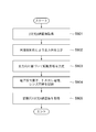
- FIG. 8 is a flowchart for explaining X-ray imaging processing according to the first embodiment.
- the main direction determination unit 3 acquires an X-ray image from the X-ray detector 2.
- the main direction determination unit 3 performs frequency analysis on the X-ray image and determines the main direction of the image. The determined main direction is notified to the control circuit 101 of the X-ray generator 1.
- the control circuit 101 performs, for example, selective driving of the electron-emitting device such that the distribution of the electron beam intensity in the main direction notified from the main direction determination unit 3 is larger than that in the other direction.
- the drive pattern of the extraction electrode 106 and the lens electrode 107 is determined.
- these are actually controlled.
- the frequency characteristic of the acquired image is analyzed, and the X-ray focal point is formed so as to have a shape in which the high frequency component extends in a small direction.
- the driving of the plurality of electron-emitting devices is controlled by the main direction determining unit 3 and the control circuit 101 according to the frequency characteristics of the image, and the electron emission distribution pattern generated by the element substrate 103 which is the electron-emitting unit is changed. Is done. Since X-rays corresponding to the emission distribution pattern are generated from the target electrode 108, the subject P is irradiated with the X-ray pattern corresponding to the emission distribution pattern. As a result, the overall current can be increased without greatly affecting the sharpness in the direction in which the high-frequency component is large.
- the X-ray irradiation dose may be set to an appropriate amount for each process.
- the X-ray irradiation amount in step S801 is sufficient at the level necessary for frequency analysis, and the X-ray irradiation amount in step S801 is made smaller than that in step S805 in order to reduce the exposure amount to the subject. Also good.
- the main direction is determined based on frequency analysis of an X-ray image, but may be determined based on an external input as another embodiment. This form will be described below.
- the main direction determination unit 3 inputs imaging information from the outside in addition to the X-ray image from the X-ray detector 2.
- the shooting information is information about the subject to be shot and information about the main direction of the subject.
- information indicating which part of the subject is the chest, limbs, abdomen, etc., information indicating the line-of-sight direction, and information indicating in which direction the subject extends in the image when the imaging part is the limb Etc. can be cited as shooting information.
- main direction determination unit 3 when the main direction determination unit 3 is realized as software of a computer, for example, an operator can directly input photographing information using an input device such as a keyboard or a mouse (not shown).
- shooting information may be input using a button or the like set in advance for each shooting target.
- the imaging apparatus is a medical imaging apparatus
- the imaging information can be input online from the radiation information system instead of being input directly by an operator's operation.
- the operation of the main direction determination unit 3 in the present embodiment will be described in the case where the imaging region is a knee joint as shown in FIG.
- the shooting information is input to the frequency analysis unit 301 as shown in FIG.
- the imaging information is the type and direction of the imaging region, and the X-ray image is a knee joint imaged in a slightly tilted state as illustrated in 6D of FIG.
- the frequency analysis unit 301 holds the direction of frequency analysis associated with the imaging region in advance in a memory (not shown). For example, when the imaging region is a limb skeleton system, 4B in FIG. The direction (A to D) shall be selected.
- the frequency analysis unit 301 rotates the four directions 6B in FIG. 6 to the four directions 6E in FIG. 6 based on the “direction” included in the input photographing information.
- the “direction” included in the imaging information is, for example, the direction (angle) of the imaging target input from the keyboard by the operator.
- four data strings are generated in the same manner as described in the first embodiment, and the frequency spectrum is calculated. Since the subsequent operation of the main direction determination unit 3 is the same as that of the first embodiment, the description thereof is omitted.
- the second embodiment differs from the first embodiment in that the subject is in a slightly rotated state, so the main direction ⁇ is a pattern exemplified in 4A to 4E in FIG. May not exactly match. In this case, a pattern closest to one of the patterns is selected.
- the control circuit 101 may adjust the driving current of each electron-emitting device 104 so that the distribution of the electron beam intensity formed on the target electrode 108 is long in the main direction.
- the same effect as in the first embodiment can be obtained. That is, it is possible to realize an overall high current without greatly affecting the sharpness in the direction in which the high frequency component is large.
- imaging information such as an imaging region and direction is input, and frequency analysis is performed using the imaging information when determining the main direction.
- the shape of the X-ray focal point is changed according to the main direction of the subject, and the sharpness of the image is ensured according to the subject.
- an X-ray imaging apparatus that ensures sharpness even in a direction with a long X-ray focal point will be described.
- the image processing unit 4 shown in FIG. 1 performs a sharpening process (frequency enhancement process) on the input X-ray image based on the main direction ⁇ determined by the main direction determining unit 3. It is characterized by that.
- FIG. 7 is a block diagram showing the configuration of the image processing unit 4.
- the X-ray image I input from the X-ray detector 2 is input to the high frequency component calculation unit 402.
- the main direction ⁇ input from the main direction determination unit 3 is input to the filter selection unit 401, and a high-frequency component extraction filter corresponding to the main direction is selected.
- the high frequency component calculation unit 402 performs a convolution operation on the input image I using a selected filter to extract the high frequency component Ih, and outputs this to the adder 403.
- the adder 403 adds the input image I and the high frequency component Ih and outputs a sharpened image Ie.
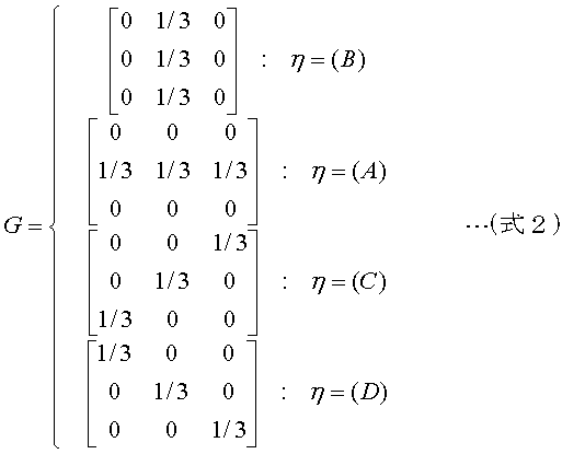
- the filter selection unit 401 selects the optimum filter G from the four types of filters based on whether the input main direction ⁇ is the direction indicated by 6B in FIG. 6 and outputs the selected filter G to the high frequency component calculation unit 402.
- the main direction ⁇ is a direction with less high frequency components.
- the high frequency component calculation unit 402 performs a convolution operation on the input image I using the filter G to obtain a high frequency component Ih, and outputs this to the adder 403.
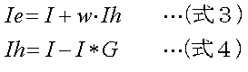
- the adder 403 adds the high frequency component Ih weighted to the input image I. Therefore, the above processing is expressed by the following expressions (Expression 3) and (Expression 4).
- * represents a convolution operation.
- w represents a weighting coefficient, and is assumed to be stored in a memory (not shown) that can be read by the image processing unit 4. Note that the value of w may be determined in advance by experiment or the like, or an optimal value is determined according to the imaging region as described in the second embodiment, and selected from the input imaging information. You may make it do.
- the X-ray focal spot shape extends in the direction with a small high-frequency component (corresponding to the direction B in 6B in FIG. 6 in the above example), so that the sharpness in this direction decreases.
- the high-frequency component in the direction is selectively emphasized by image processing. That is, in the third embodiment, the frequency enhancement processing is performed on the two-dimensional X-ray image so that the high-frequency component in the main direction is relatively enhanced with respect to the other directions, so that the sharpness is anisotropic. To be corrected.
- Image processing by the image processing unit 4 described in the third embodiment is not limited to the above-described method, and can take various forms.
- the present invention can be applied even when the subject is inclined and the direction thereof is an arbitrary angle.
- an example of the image processing unit 4 that can correspond to the main direction at an arbitrary angle will be described.
- the filter selection part 401 and the high frequency component calculating part 402 are implement
- the filter can be rotated at an arbitrary angle, and a detailed description thereof is omitted because it is described in the document.
- the operation will be described below as a function of the processing block 404 in which the filter selection unit 401 and the high frequency component calculation unit 402 in FIG. 7 are combined.
- Non-patent literature W. T. Freeman and E. H. Adelson, “The design and use of steerable filters”, IEEE Trans.Pattern Analysis and Machine Intelligence, Vol.13No.9, pp891-906, 1991
- the processing block 404 calculates the high frequency component Ih as follows based on the main direction ⁇ .
- the main direction ⁇ represents an arbitrary angle ([degree]).
- the main direction ⁇ is a direction with less high frequency components.
- the high-frequency component Ih obtained by (Equation 5) is a component in which the main direction ⁇ is emphasized, and by processing this according to (Equation 3), the sharpness in the direction can be increased.
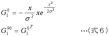
- G 0 1 and G 90 1 are filters corresponding to the first derivative of the Gaussian distribution in the horizontal and vertical directions, and are calculated by the following equations in this embodiment.
- G 0 1 T is the transpose of G 0 1.
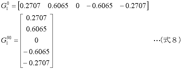
- the actual filter coefficient can be calculated by determining x in (Expression 6) by the following expression.
- N is the size of the basic filter
- Z is a set of integers.
- the filter coefficients are as follows.
- the filter size and standard deviation ⁇ are selected in advance according to the size of the X-ray focal point F, the MTF of the X-ray detector 2, the positional relationship between the X-ray focal point F and the subject P, the X-ray detector 2, and the like. It is preferable to be able to do so.
- MTF is a modulation transfer function and an index of sharpness.
- the filter selection unit 401 stores in advance a filter calculated from a plurality of sizes and standard deviations in a memory (not shown). As the X-ray focal point F becomes larger or the ratio b / a between the distance a between the X-ray focal point F and the subject P and the distance b between the X-ray detector 2 and the subject P shown in FIG. A filter having a large size or standard deviation ⁇ may be selected so that the effect of emphasis is strong.
- the adder 403 may emphasize higher frequencies by increasing w.
- the MTF, distance ratio b / a, and the like of the X-ray detector 2 described above may be stored in advance in, for example, a memory in the X-ray imaging apparatus, or a table or C on which the subject P is placed during imaging. You may acquire by detecting the up-and-down movement of the type
- high-frequency components can be emphasized in an arbitrary direction. Therefore, even when the direction in which the sharpness is reduced by making the shape of the X-ray focal point anisotropic is an arbitrary angle, it can be corrected.
- the electron emitter driving circuit 102 capable of individually driving the plurality of electron emitters 104 that emit electron beams and the control circuit 101 have an arbitrary shape on the target electrode 108.
- X-ray focal point can be formed.
- an X-ray focal point shape extending in a direction along the main direction can be formed with the direction in which the high frequency component is minimized as the main direction.
- the X-ray focal point is determined from the two-dimensional X-ray image obtained by the X-ray detector 2 according to the main direction determined by the main direction determination unit 3.
- the shape is controlled. Therefore, it is possible to improve the image quality of the photographed image by achieving a large current while maintaining the sharpness according to the object to be photographed.
- the image processing unit 4 performs the sharpening process with respect to that direction. By doing, the influence on the diagnosis can be suppressed.
- the functions of the above-described embodiments are achieved by supplying a software program directly or remotely to a system or apparatus, and the computer of the system or apparatus reads and executes the supplied program code.
- the supplied program is a computer program corresponding to the flowchart shown in the drawings in the embodiment.
- the program code installed in the computer also implements the present invention.
- the present invention includes a computer program itself for realizing the functional processing of the present invention.
- program function it may be in the form of object code, a program executed by an interpreter, script data supplied to the OS, or the like.
- Examples of computer-readable storage media for supplying computer programs include the following.
- floppy (registered trademark) disk hard disk, optical disk, magneto-optical disk, MO, CD-ROM, CD-R, CD-RW, magnetic tape, nonvolatile memory card, ROM, DVD (DVD-ROM, DVD- R).
- a client computer browser is used to connect to a homepage on the Internet, and the computer program of the present invention is downloaded from the homepage to a recording medium such as a hard disk.
- the downloaded program may be a compressed file including an automatic installation function. It can also be realized by dividing the program code constituting the program of the present invention into a plurality of files and downloading each file from a different homepage. That is, a WWW server that allows a plurality of users to download a program file for realizing the functional processing of the present invention on a computer is also included in the present invention.
- the program of the present invention may be encrypted, stored in a storage medium such as a CD-ROM, and distributed to users.
- a user who has cleared a predetermined condition is allowed to download key information for decryption from a homepage via the Internet, execute an encrypted program using the key information, and install the program on the computer. You can also.
- the embodiment of the embodiment is implemented in cooperation with an OS or the like running on the computer based on an instruction of the program.
- a function may be realized.
- the OS or the like performs part or all of the actual processing, and the functions of the above-described embodiments are realized by the processing.
- the program read from the recording medium is written in a memory provided in a function expansion board inserted into the computer or a function expansion unit connected to the computer, so that part or all of the functions of the above-described embodiments are realized. May be.
- the CPU or the like provided in the function expansion board or function expansion unit performs part or all of the actual processing based on the instructions of the program.
Landscapes
- Health & Medical Sciences (AREA)
- Life Sciences & Earth Sciences (AREA)
- Engineering & Computer Science (AREA)
- Medical Informatics (AREA)
- Radiology & Medical Imaging (AREA)
- Molecular Biology (AREA)
- Biophysics (AREA)
- Nuclear Medicine, Radiotherapy & Molecular Imaging (AREA)
- Optics & Photonics (AREA)
- Pathology (AREA)
- Physics & Mathematics (AREA)
- Biomedical Technology (AREA)
- Heart & Thoracic Surgery (AREA)
- High Energy & Nuclear Physics (AREA)
- Surgery (AREA)
- Animal Behavior & Ethology (AREA)
- General Health & Medical Sciences (AREA)
- Public Health (AREA)
- Veterinary Medicine (AREA)
- Human Computer Interaction (AREA)
- X-Ray Techniques (AREA)
- Apparatus For Radiation Diagnosis (AREA)
Abstract
Description
複数の電子放出素子を有し、駆動された電子放出素子に対応した電子ビームを発生する電子ビーム発生手段と、
前記電子ビーム発生手段で発生した電子ビームの照射位置をX線焦点としたX線を発生するターゲット電極と、
前記複数の電子放出素子の駆動を個別に制御することにより、前記ターゲット電極における、X線焦点の集合によって形成されるX線焦点形状を制御する駆動制御手段とを備える。
複数の電子放出素子を有し、駆動された電子放出素子に対応した電子ビームを発生する電子ビーム発生手段と、
前記電子ビーム発生手段で発生した電子ビームの照射位置をX線焦点としたX線を発生するターゲット電極と、
前記複数の電子放出素子の駆動を個別に制御することにより、前記ターゲット電極における、X線焦点の集合によって形成されるX線焦点形状を制御する駆動制御手段と、
前記ターゲット電極から発生したX線を検出することにより2次元X線画像を生成する検出手段と、
前記検出手段で検出された前記2次元X線画像に基づいて、前記駆動制御手段が前記ターゲット電極に形成すべき前記X線焦点形状を決定する決定手段とを備える。
図1は第1実施形態に係るX線撮影装置の構成を示す図である。図1においてX線発生装置1から照射されたX線XRは被写体Pを透過し、X線検出器2に入射する。X線検出器2はX線画像用の平面検出器であり、被写体Pを透過して減弱したX線の強度分布を画像として主方向決定部3および画像処理部4に出力する。


前述した第1実施形態においては、主方向の決定はX線撮影された画像の周波数解析に基づいて行われたが、他の実施の形態として外部入力に基づいて決定するようにしても良い。以下にこの形態について説明する。
第1実施形態、第2実施形態においては被写体の主方向に応じてX線焦点の形状を変更し、被写体に応じて画像の鮮鋭度を確保するようにした。第3実施形態ではX線焦点が長い方向に対しても鮮鋭度を確保するX線撮影装置について説明する。
第3実施形態で説明した画像処理部4による画像処理は上述の方法に限定されず、様々な形態を取ることが可能である。例えば、第2実施形態において例示したように被写体が傾いており、その方向が任意の角度であっても本発明を適用することが可能である。以下に、任意の角度の主方向に対応可能な画像処理部4の例を説明する。
[非特許文献] W. T. Freeman and E. H. Adelson, “The design and use ofsteerable filters”, IEEE Trans.Pattern Analysis and Machine Intelligence, Vol.13No.9,pp891-906, 1991


尚、本発明は、ソフトウェアのプログラムをシステム或いは装置に直接或いは遠隔から供給し、そのシステム或いは装置のコンピュータが該供給されたプログラムコードを読み出して実行することによって前述した実施形態の機能が達成される場合を含む。この場合、供給されるプログラムは実施形態で図に示したフローチャートに対応したコンピュータプログラムである。
Claims (15)
- 複数の電子放出素子を有し、駆動された電子放出素子に対応した電子ビームを発生する電子ビーム発生手段と、
前記電子ビーム発生手段で発生した電子ビームの照射位置をX線焦点としたX線を発生するターゲット電極と、
前記複数の電子放出素子の駆動を個別に制御することにより、前記ターゲット電極における、X線焦点の集合によって形成されるX線焦点形状を制御する駆動制御手段とを備えることを特徴とするX線発生装置。 - 前記電子ビーム発生手段と前記ターゲット電極との間に設けられ、前記電子ビームの形成を行うためのレンズ電極を更に備え、
前記駆動制御手段は、前記複数の電子放出素子の駆動及び前記レンズ電極の駆動を制御することにより、前記ターゲット電極に形成される前記X線焦点形状を制御することを特徴とする請求項1に記載のX線発生装置。 - 複数の電子放出素子を有し、駆動された電子放出素子に対応した電子ビームを発生する電子ビーム発生手段と、
前記電子ビーム発生手段で発生した電子ビームの照射位置をX線焦点としたX線を発生するターゲット電極と、
前記ターゲット電極から発生したX線を検出することにより2次元X線画像を生成する検出手段と、
前記複数の電子放出素子の駆動を個別に制御することにより、前記ターゲット電極における、X線焦点の集合によって形成されるX線焦点形状を制御する駆動制御手段と、
前記検出手段で検出された前記2次元X線画像に基づいて、前記駆動制御手段が前記ターゲット電極に形成すべき前記X線焦点形状を決定する決定手段とを備えることを特徴とするX線撮影装置。 - 前記駆動制御手段は、
前記2次元X線画像に対して複数の方向において周波数解析を行い、高周波成分が最小となる方向を主方向として決定する主方向決定手段を有し、
前記主方向に基づいて前記ターゲット電極に形成すべき前記X線焦点形状を決定することを特徴とする請求項3に記載のX線撮影装置。 - 撮影対象の部位を示す情報を含む撮影情報を入力する入力手段を更に備え、
前記主方向決定手段は、前記周波数解析を行なうべき複数の方向を、前記撮影情報が示す前記撮影対象の部位に基づいて選択することを特徴とする請求項4に記載のX線撮影装置。 - 前記撮影情報はさらに前記2次元X線画像における対象の方向を示す情報を含み、
前記主方向決定手段は、前記撮影対象に基づいて選択された、周波数解析すべき複数の方向を、前記対象の方向を示す情報に基づいて回転させることを特徴とする請求項5に記載のX線撮影装置。 - 前記電子ビーム発生手段と前記ターゲット電極との間に設けられ、前記電子ビームの形成を行うためのレンズ電極を更に備え、
前記駆動制御手段は、前記ターゲット電極上の電子線強度の前記主方向に平行な方向への分布が他の方向への分布よりも相対的に長く広がるように、前記複数の電子放出素子の駆動及び前記レンズ電極の駆動を制御することを特徴とする請求項請求項4乃至6のいずれか1項に記載のX線撮影装置。 - 前記検出手段で検出された2次元X線画像に対して周波数強調処理を行う画像処理手段を更に備え、
前記画像処理手段は、前記主方向の高周波成分を他の方向に対して相対的に強調することを特徴とする請求項4乃至請求項7のいずれか1項に記載のX線撮影装置。 - X線を発生するX線発生装置であって、
複数の電子放出素子で構成される電子放出手段と、
前記電子放出素子の駆動を制御することで前記電子放出手段が発生する電子の放出分布パターンを変える制御手段と、
前記電子放出手段が放出した電子を加速する加速手段と、
前記加速手段で加速した電子が衝突することでX線を発生するX線発生手段とを備えることを特徴とするX線発生装置。 - 複数の電子放出素子を有し、駆動された電子放出素子に対応した電子ビームを発生する電子ビーム発生手段と、
前記電子ビーム発生手段で発生した電子ビームの照射位置をX線焦点としたX線を発生するターゲット電極と
を備えたX線発生装置の制御方法であって、
前記複数の電子放出素子の駆動を個別に制御することにより、前記ターゲット電極における、X線焦点の集合によって形成されるX線焦点形状を制御する駆動制御工程を備えることを特徴とするX線発生装置の制御方法。 - 複数の電子放出素子を有し、駆動された電子放出素子に対応した電子ビームを発生する電子ビーム発生手段と、
前記電子ビーム発生手段で発生した電子ビームの照射位置をX線焦点としたX線を発生するターゲット電極と、
前記ターゲット電極から発生したX線を検出することにより2次元X線画像を生成する検出手段とを備えたX線撮影装置の制御方法であって、
前記複数の電子放出素子の駆動を個別に制御することにより、前記ターゲット電極における、X線焦点の集合によって形成されるX線焦点形状を制御する駆動制御工程と、
前記検出手段で検出された前記2次元X線画像に基づいて、前記駆動制御工程で前記ターゲット電極に形成されるべき前記X線焦点形状を決定する決定工程とを備えることを特徴とするX線撮影装置の制御方法。 - X線を発生するX線発生装置の制御方法であって、
電子放出手段が有する複数の電子放出素子の駆動を制御することで前記電子放出手段が発生する電子の放出分布パターンを変える制御工程と、
前記電子放出手段が放出した電子を加速させてX線発生手段に衝突させることでX線を発生するX線発生工程とを有することを特徴とするX線発生装置の制御方法。 - 請求項10または12に記載のX線発生装置の制御方法をコンピュータに実行させるプログラム。
- 請求項11に記載のX線撮影装置の制御方法をコンピュータに実行させるプログラム。
- 請求項13または14に記載のプログラムを格納したコンピュータ読み取り可能な記憶媒体。
Priority Applications (5)
| Application Number | Priority Date | Filing Date | Title |
|---|---|---|---|
| EP20090711441 EP2197251A4 (en) | 2008-02-13 | 2009-02-04 | X-RAY GENERATOR, X-RAY VIEWING DEVICE, AND METHOD FOR CONTROLLING GENERATOR AND DEVICE |
| CN2009801045666A CN101940066A (zh) | 2008-02-13 | 2009-02-04 | X射线发生器、x射线成像设备及其控制方法 |
| KR1020107012271A KR101143081B1 (ko) | 2008-02-13 | 2009-02-04 | X선 발생 장치, x선 촬영 장치 및 그들의 제어 방법 |
| US12/745,437 US8488742B2 (en) | 2008-02-13 | 2009-02-04 | X-ray generator, X-ray imaging apparatus, and control methods therefor |
| US13/930,390 US8879687B2 (en) | 2008-02-13 | 2013-06-28 | X-ray generator, X-ray imaging apparatus, and control methods therefor |
Applications Claiming Priority (2)
| Application Number | Priority Date | Filing Date | Title |
|---|---|---|---|
| JP2008032351A JP4886713B2 (ja) | 2008-02-13 | 2008-02-13 | X線撮影装置及びその制御方法 |
| JP2008-032351 | 2008-02-13 |
Related Child Applications (2)
| Application Number | Title | Priority Date | Filing Date |
|---|---|---|---|
| US12/745,437 A-371-Of-International US8488742B2 (en) | 2008-02-13 | 2009-02-04 | X-ray generator, X-ray imaging apparatus, and control methods therefor |
| US13/930,390 Continuation US8879687B2 (en) | 2008-02-13 | 2013-06-28 | X-ray generator, X-ray imaging apparatus, and control methods therefor |
Publications (1)
| Publication Number | Publication Date |
|---|---|
| WO2009101882A1 true WO2009101882A1 (ja) | 2009-08-20 |
Family
ID=40956912
Family Applications (1)
| Application Number | Title | Priority Date | Filing Date |
|---|---|---|---|
| PCT/JP2009/051853 Ceased WO2009101882A1 (ja) | 2008-02-13 | 2009-02-04 | X線発生装置、x線撮影装置及びそれらの制御方法 |
Country Status (6)
| Country | Link |
|---|---|
| US (2) | US8488742B2 (ja) |
| EP (1) | EP2197251A4 (ja) |
| JP (1) | JP4886713B2 (ja) |
| KR (1) | KR101143081B1 (ja) |
| CN (1) | CN101940066A (ja) |
| WO (1) | WO2009101882A1 (ja) |
Cited By (2)
| Publication number | Priority date | Publication date | Assignee | Title |
|---|---|---|---|---|
| JP2014121607A (ja) * | 2012-12-21 | 2014-07-03 | Siemens Aktiengesellschaft | 位相ステッピングによる検査対象の微分位相コントラストイメージングのためのx線撮影システムならびにアンギオグラフィ検査方法 |
| US8879687B2 (en) | 2008-02-13 | 2014-11-04 | Canon Kabushiki Kaisha | X-ray generator, X-ray imaging apparatus, and control methods therefor |
Families Citing this family (18)
| Publication number | Priority date | Publication date | Assignee | Title |
|---|---|---|---|---|
| JP2012066062A (ja) * | 2010-08-24 | 2012-04-05 | Fujifilm Corp | 放射線撮影システム及び放射線撮影方法 |
| US9599577B2 (en) * | 2010-09-06 | 2017-03-21 | Koninklijke Philips N.V. | X-ray imaging with pixelated detector |
| JP5901180B2 (ja) * | 2011-08-31 | 2016-04-06 | キヤノン株式会社 | 透過型x線発生装置及びそれを用いたx線撮影装置 |
| JP5871529B2 (ja) | 2011-08-31 | 2016-03-01 | キヤノン株式会社 | 透過型x線発生装置及びそれを用いたx線撮影装置 |
| US10242836B2 (en) * | 2012-03-16 | 2019-03-26 | Nanox Imaging Plc | Devices having an electron emitting structure |
| WO2013184213A2 (en) * | 2012-05-14 | 2013-12-12 | The General Hospital Corporation | A distributed, field emission-based x-ray source for phase contrast imaging |
| DE102012110864B4 (de) | 2012-11-12 | 2014-08-21 | Gsi Helmholtzzentrum Für Schwerionenforschung Gmbh | Bewegungsrobuste Bestrahlungsplanung mittels Teilbestrahlungsplänen |
| JP6188470B2 (ja) * | 2013-07-24 | 2017-08-30 | キヤノン株式会社 | 放射線発生装置及びそれを用いた放射線撮影システム |
| CN104470179B (zh) * | 2013-09-23 | 2017-10-24 | 清华大学 | 一种产生均整x射线辐射场的装置以及方法 |
| CN105374654B (zh) * | 2014-08-25 | 2018-11-06 | 同方威视技术股份有限公司 | 电子源、x射线源、使用了该x射线源的设备 |
| JP6441015B2 (ja) * | 2014-10-06 | 2018-12-19 | キヤノンメディカルシステムズ株式会社 | X線診断装置及びx線管制御方法 |
| GB2531326B (en) * | 2014-10-16 | 2020-08-05 | Adaptix Ltd | An X-Ray emitter panel and a method of designing such an X-Ray emitter panel |
| US10991539B2 (en) * | 2016-03-31 | 2021-04-27 | Nano-X Imaging Ltd. | X-ray tube and a conditioning method thereof |
| US11282668B2 (en) * | 2016-03-31 | 2022-03-22 | Nano-X Imaging Ltd. | X-ray tube and a controller thereof |
| CN110664420B (zh) * | 2019-10-11 | 2023-04-07 | 上海联影医疗科技股份有限公司 | 焦点校正方法、装置、计算机设备和计算机可读存储介质 |
| DE102020206938B4 (de) * | 2020-06-03 | 2022-03-31 | Siemens Healthcare Gmbh | Beeinflussung eines Brennflecks |
| EP4425528A1 (de) * | 2023-02-28 | 2024-09-04 | Siemens Healthineers AG | Feldeffekt-elektronenemitter mit gruppierten teilemissionsflächen |
| EP4478393A1 (de) * | 2023-06-16 | 2024-12-18 | Siemens Healthineers AG | Elektronenemitter mit einer rotierbaren emissionsfläche |
Citations (7)
| Publication number | Priority date | Publication date | Assignee | Title |
|---|---|---|---|---|
| JPH0613195A (ja) * | 1992-06-29 | 1994-01-21 | Shimadzu Corp | X線透視撮影装置 |
| JPH08264139A (ja) | 1995-03-22 | 1996-10-11 | Hamamatsu Photonics Kk | X線発生装置 |
| JPH09180894A (ja) | 1995-12-22 | 1997-07-11 | Ebara Corp | X線源 |
| JP2003100242A (ja) * | 2001-06-27 | 2003-04-04 | Ge Medical Systems Global Technology Co Llc | X線発生装置内で電子ビームを発生する方法及びシステム |
| JP2005237779A (ja) | 2004-02-27 | 2005-09-08 | Shimadzu Corp | X線ct装置 |
| JP2007504636A (ja) * | 2003-05-30 | 2007-03-01 | シンテック,インコーポレイテッド | 複数位置から複数のx線ビームを生成するための装置及び方法 |
| WO2007100105A1 (ja) * | 2006-03-03 | 2007-09-07 | Canon Kabushiki Kaisha | マルチx線発生装置およびマルチx線撮影装置 |
Family Cites Families (10)
| Publication number | Priority date | Publication date | Assignee | Title |
|---|---|---|---|---|
| GB1464249A (en) * | 1973-11-20 | 1977-02-09 | Roeck W W | Apparatus for use in the determination of focal spot size in x-ray tubes |
| DE3022968A1 (de) * | 1980-06-19 | 1981-12-24 | Siemens AG, 1000 Berlin und 8000 München | Messgeraet fuer den optischen brennfleck |
| JPS6429764U (ja) | 1987-08-17 | 1989-02-22 | ||
| US5566220A (en) | 1992-12-04 | 1996-10-15 | Kabushiki Kaisha Toshiba | X-ray computerized tomography apparatus |
| US6980627B2 (en) * | 2000-10-06 | 2005-12-27 | Xintek, Inc. | Devices and methods for producing multiple x-ray beams from multiple locations |
| US6480572B2 (en) * | 2001-03-09 | 2002-11-12 | Koninklijke Philips Electronics N.V. | Dual filament, electrostatically controlled focal spot for x-ray tubes |
| WO2006130630A2 (en) * | 2005-05-31 | 2006-12-07 | The University Of North Carolina At Chapel Hill | X-ray pixel beam array systems and methods for electronically shaping radiation fields and modulating radiation field intensity patterns for radiotherapy |
| JP2007066694A (ja) * | 2005-08-31 | 2007-03-15 | Hamamatsu Photonics Kk | X線管 |
| US7809114B2 (en) * | 2008-01-21 | 2010-10-05 | General Electric Company | Field emitter based electron source for multiple spot X-ray |
| JP4886713B2 (ja) | 2008-02-13 | 2012-02-29 | キヤノン株式会社 | X線撮影装置及びその制御方法 |
-
2008
- 2008-02-13 JP JP2008032351A patent/JP4886713B2/ja not_active Expired - Fee Related
-
2009
- 2009-02-04 CN CN2009801045666A patent/CN101940066A/zh active Pending
- 2009-02-04 EP EP20090711441 patent/EP2197251A4/en not_active Withdrawn
- 2009-02-04 KR KR1020107012271A patent/KR101143081B1/ko not_active Expired - Fee Related
- 2009-02-04 WO PCT/JP2009/051853 patent/WO2009101882A1/ja not_active Ceased
- 2009-02-04 US US12/745,437 patent/US8488742B2/en not_active Expired - Fee Related
-
2013
- 2013-06-28 US US13/930,390 patent/US8879687B2/en not_active Expired - Fee Related
Patent Citations (7)
| Publication number | Priority date | Publication date | Assignee | Title |
|---|---|---|---|---|
| JPH0613195A (ja) * | 1992-06-29 | 1994-01-21 | Shimadzu Corp | X線透視撮影装置 |
| JPH08264139A (ja) | 1995-03-22 | 1996-10-11 | Hamamatsu Photonics Kk | X線発生装置 |
| JPH09180894A (ja) | 1995-12-22 | 1997-07-11 | Ebara Corp | X線源 |
| JP2003100242A (ja) * | 2001-06-27 | 2003-04-04 | Ge Medical Systems Global Technology Co Llc | X線発生装置内で電子ビームを発生する方法及びシステム |
| JP2007504636A (ja) * | 2003-05-30 | 2007-03-01 | シンテック,インコーポレイテッド | 複数位置から複数のx線ビームを生成するための装置及び方法 |
| JP2005237779A (ja) | 2004-02-27 | 2005-09-08 | Shimadzu Corp | X線ct装置 |
| WO2007100105A1 (ja) * | 2006-03-03 | 2007-09-07 | Canon Kabushiki Kaisha | マルチx線発生装置およびマルチx線撮影装置 |
Non-Patent Citations (2)
| Title |
|---|
| See also references of EP2197251A4 * |
| W. T. FREEMAN; E. H. ADELSON: "The design and use of steerable filters", IEEE TRANS. PATTERN ANALYSIS AND MACHINE INTELLIGENCE, vol. 13, no. 9, 1991, pages 891 - 906 |
Cited By (2)
| Publication number | Priority date | Publication date | Assignee | Title |
|---|---|---|---|---|
| US8879687B2 (en) | 2008-02-13 | 2014-11-04 | Canon Kabushiki Kaisha | X-ray generator, X-ray imaging apparatus, and control methods therefor |
| JP2014121607A (ja) * | 2012-12-21 | 2014-07-03 | Siemens Aktiengesellschaft | 位相ステッピングによる検査対象の微分位相コントラストイメージングのためのx線撮影システムならびにアンギオグラフィ検査方法 |
Also Published As
| Publication number | Publication date |
|---|---|
| US20100310051A1 (en) | 2010-12-09 |
| JP4886713B2 (ja) | 2012-02-29 |
| EP2197251A1 (en) | 2010-06-16 |
| EP2197251A4 (en) | 2011-07-13 |
| US8488742B2 (en) | 2013-07-16 |
| KR20100077048A (ko) | 2010-07-06 |
| CN101940066A (zh) | 2011-01-05 |
| US20130294580A1 (en) | 2013-11-07 |
| KR101143081B1 (ko) | 2012-05-08 |
| JP2009189507A (ja) | 2009-08-27 |
| US8879687B2 (en) | 2014-11-04 |
Similar Documents
| Publication | Publication Date | Title |
|---|---|---|
| JP4886713B2 (ja) | X線撮影装置及びその制御方法 | |
| JP5683116B2 (ja) | 放射線撮影装置、その制御方法及びプログラム | |
| JP4977201B2 (ja) | マルチx線発生装置のための制御装置、制御方法、及びコンピュータ可読メモリ | |
| JP5877985B2 (ja) | 電子ビーム・システムを動作させる方法及びシステム | |
| JP2021115376A (ja) | X線ct装置およびx線高電圧装置 | |
| EP3294044B1 (en) | X-ray tube with gridding electrode | |
| US8938050B2 (en) | Low bias mA modulation for X-ray tubes | |
| KR20100109381A (ko) | 방사선 촬영장치 | |
| US8755488B2 (en) | Voltage modulated x-ray tube | |
| CN103081024B (zh) | 利用像素化探测器的x射线成像 | |
| JP5677534B2 (ja) | 放射線撮影装置及びその制御方法 | |
| JP5914625B2 (ja) | 放射線撮影装置及びその制御方法 | |
| JP2021191404A (ja) | 画像処理装置、放射線画像撮影システム、画像処理方法、及び画像処理プログラム | |
| JP2019523876A (ja) | 対象物をx線イメージングするための装置 | |
| JP7698996B2 (ja) | X線診断装置、x線診断方法、およびプログラム | |
| JP2020049059A (ja) | 医用画像処理装置および方法 | |
| JP2011098233A (ja) | マルチx線撮影装置及びその制御方法 | |
| JP2021191403A (ja) | 制御装置、放射線画像撮影システム、制御処理方法、及び制御処理プログラム | |
| JP2008073342A (ja) | 放射線画像撮影システム及び放射線画像撮影方法 | |
| JP2021191402A (ja) | 画像処理装置、放射線画像撮影システム、画像処理方法、及び画像処理プログラム | |
| US11179123B2 (en) | Radiography apparatus, radiography apparatus operation method, and radiography apparatus operation program | |
| KR102801623B1 (ko) | 하이브리드 펄스를 이용한 엑스선 영상 획득 및 처리 방법, 장치 및 시스템 | |
| EP3013237B1 (en) | Imaging apparatus | |
| JP2011167467A (ja) | X線ct装置 | |
| JP2008119468A (ja) | Cbct型x線撮像の方法とアッセンブリ |
Legal Events
| Date | Code | Title | Description |
|---|---|---|---|
| WWE | Wipo information: entry into national phase |
Ref document number: 200980104566.6 Country of ref document: CN |
|
| 121 | Ep: the epo has been informed by wipo that ep was designated in this application |
Ref document number: 09711441 Country of ref document: EP Kind code of ref document: A1 |
|
| WWE | Wipo information: entry into national phase |
Ref document number: 2009711441 Country of ref document: EP |
|
| WWE | Wipo information: entry into national phase |
Ref document number: 12745437 Country of ref document: US |
|
| ENP | Entry into the national phase |
Ref document number: 20107012271 Country of ref document: KR Kind code of ref document: A |
|
| NENP | Non-entry into the national phase |
Ref country code: DE |