WO2009104247A1 - Procédé de correction d'erreur de déplacement de dispositif de transfert de plateau et programme de correction - Google Patents
Procédé de correction d'erreur de déplacement de dispositif de transfert de plateau et programme de correction Download PDFInfo
- Publication number
- WO2009104247A1 WO2009104247A1 PCT/JP2008/052745 JP2008052745W WO2009104247A1 WO 2009104247 A1 WO2009104247 A1 WO 2009104247A1 JP 2008052745 W JP2008052745 W JP 2008052745W WO 2009104247 A1 WO2009104247 A1 WO 2009104247A1
- Authority
- WO
- WIPO (PCT)
- Prior art keywords
- correction
- tray
- torque
- transfer device
- limit value
- Prior art date
- Legal status (The legal status is an assumption and is not a legal conclusion. Google has not performed a legal analysis and makes no representation as to the accuracy of the status listed.)
- Ceased
Links
Images




Classifications
-
- G—PHYSICS
- G01—MEASURING; TESTING
- G01R—MEASURING ELECTRIC VARIABLES; MEASURING MAGNETIC VARIABLES
- G01R31/00—Arrangements for testing electric properties; Arrangements for locating electric faults; Arrangements for electrical testing characterised by what is being tested not provided for elsewhere
- G01R31/28—Testing of electronic circuits, e.g. by signal tracer
- G01R31/2851—Testing of integrated circuits [IC]
- G01R31/2886—Features relating to contacting the IC under test, e.g. probe heads; chucks
- G01R31/2891—Features relating to contacting the IC under test, e.g. probe heads; chucks related to sensing or controlling of force, position, temperature
-
- G—PHYSICS
- G01—MEASURING; TESTING
- G01R—MEASURING ELECTRIC VARIABLES; MEASURING MAGNETIC VARIABLES
- G01R31/00—Arrangements for testing electric properties; Arrangements for locating electric faults; Arrangements for electrical testing characterised by what is being tested not provided for elsewhere
- G01R31/28—Testing of electronic circuits, e.g. by signal tracer
- G01R31/2851—Testing of integrated circuits [IC]
- G01R31/2893—Handling, conveying or loading, e.g. belts, boats, vacuum fingers
Definitions
- the present invention relates to a method for correcting a movement error generated in a tray transfer device for transferring a tray capable of accommodating various electronic components (hereinafter also referred to as IC devices) such as semiconductor integrated circuit elements, and for correction. Regarding the program.
- IC devices electronic components
- an electronic component testing apparatus In the manufacturing process of an IC device, an electronic component testing apparatus is used to test the performance and function of the IC device in a packaged state.
- a handler that constitutes the electronic component test apparatus includes a storage unit that stores a customer tray that stores an IC device to be tested and a customer tray that stores a tested IC device classified according to a test result. It has.
- the storage unit includes a stocker that stores a plurality of customer trays, a lifting device that holds the customer tray and can be moved up and down, and a tray transfer device that transfers the customer tray between the lifting device and the stocker. And have.
- the tray transfer device may have an assembly error during manufacturing, or an error may occur with use. For this reason, the movement error of the tray transfer device is corrected when the handler is completed or during regular maintenance.
- the problem to be solved by the present invention is to provide a correction method and a correction program capable of making the correction accuracy constant and improving the productivity.
- a method for correcting a movement error generated in a tray transfer device for transferring a tray for accommodating electronic devices under test the tray transfer device.
- a first storage step for storing the position as a first boundary point and the jig by the tray transfer device while measuring the torque of the motor
- a second exploration step for moving the motor in a second direction different from the first direction, and when the motor torque exceeds the first limit value, the position is set as a second boundary point.
- a correction method comprising: a second storing step, and a calculating step for calculating actual real coordinates of the correction target position with reference to the first boundary point and the second boundary point. Is done.
- the second direction in the second exploration step is a direction substantially opposite to the first direction, and in the calculation step, the first boundary point and It is preferable to calculate the midpoint of the second boundary point as the real coordinates.
- the limit torque for stopping the motor is changed from the second limit value used in normal operation to the first limit value for correction. It is preferable that a torque reduction step for reducing the torque is provided.
- a torque increasing step for increasing the limit torque of the motor from the first limit value to the second limit value simultaneously with or after the second storage step is preferable to provide.
- the torque of the motor exceeds the first limit value when the jig contacts an obstacle. Is preferred.
- the correction target position is a mounting position on a holding device for holding the tray, and the obstacle is the holding for guiding the tray to the holding device.
- the obstacle is the holding for guiding the tray to the holding device.
- it is a guide pin of the device.
- the correction target position is a placement position on a stocker that stacks and accommodates a plurality of the trays, and the obstacle is the one for aligning the stacked trays.
- the frame is preferably a stocker frame.
- a correction amount is calculated from the coordinates before correction of the correction target position used in the transfer step and the actual coordinates of the correction target position calculated in the calculation step, It is preferable to include a confirmation step for confirming whether or not the correction amount is within a predetermined range, and a warning step for giving a warning when the correction amount is outside the predetermined range.
- the jig preferably has substantially the same outer shape as the tray.
- a storage step of storing the correction amount in a storage device it is preferable to include a storage step of storing the correction amount in a storage device.
- the first search step, the first storage step, the second search step, and the second storage step are repeated a plurality of times. It is preferable to calculate the real coordinates with reference to one boundary point and a plurality of the second boundary points.
- the correction target is stored on the basis of a second storage step of storing the position as a second boundary point, and the first boundary point and the second boundary point.
- a correction program for causing the control device to execute a calculation step of calculating actual real coordinates of the position is provided.
- the second direction in the second exploration step is a direction substantially opposite to the first direction, and in the calculation step, the first boundary point and It is preferable to calculate the midpoint of the second boundary point as the real coordinates.
- the limit torque for stopping the motor is changed from the second limit value used in normal operation to the first limit value for correction. It is preferable to cause the control device to execute a torque reduction step for reducing the torque.
- a torque increasing step for increasing the limit torque of the motor from the first limit value to the second limit value simultaneously with or after the second storage step.
- the control device is preferably executed.
- the torque of the motor exceeds the first limit value when the jig contacts an obstacle. Is preferred.
- the correction target position is a mounting position on a holding device for holding the tray, and the obstacle is the holding for guiding the tray to the holding device.
- the obstacle is the holding for guiding the tray to the holding device.
- it is a guide pin of the device.
- the correction target position is a placement position on a stocker that stacks and accommodates a plurality of the trays, and the obstacle is the one for aligning the stacked trays.
- the frame is preferably a stocker frame.
- a correction amount is calculated from the coordinates before correction of the correction target position used in the transfer step and the actual coordinates of the correction target position calculated in the calculation step, and the correction It is preferable to cause the control device to execute a confirmation step for confirming whether the amount is within a predetermined range and a warning step for giving a warning when the correction amount is outside the predetermined range.
- the jig preferably has substantially the same outer shape as the tray.
- control device executes a storage step of storing the correction amount in a storage device.
- the first search step, the first storage step, the second search step, and the second storage step are repeated a plurality of times. It is preferable to calculate the real coordinates with reference to one boundary point and a plurality of the second boundary points.
- a tray transfer device for transferring a tray for accommodating electronic devices under test, and a control device for controlling a motor for moving the tray. And a storage device that stores the program, and the control device is provided with a tray transfer device that executes the program.
- the actual coordinates of the correction target position are calculated based on the first boundary point and the second boundary point detected by moving the jig in the first and second directions by the tray transfer device. . Therefore, since the movement error of the tray transfer device can be automatically corrected, the correction accuracy can be made constant and the productivity can be improved.
- FIG. 1 is a side view showing an entire electronic component testing apparatus according to an embodiment of the present invention.
- FIG. 2 is a perspective view of the electronic component testing apparatus of FIG.
- FIG. 3 is a conceptual diagram showing a tray handling method in the electronic component testing apparatus of FIG.
- FIG. 4 is a front view showing a storage unit of the electronic device test apparatus according to the embodiment of the present invention.
- FIG. 5 is a side view showing a storage unit of the electronic device test apparatus according to the embodiment of the present invention.
- FIG. 6 is an exploded perspective view showing an IC stocker used in the electronic component test apparatus according to the embodiment of the present invention.
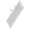
- FIG. 7 is a perspective view showing a customer tray used in the electronic component testing apparatus according to the embodiment of the present invention.
- FIG. 1 is a side view showing an entire electronic component testing apparatus according to an embodiment of the present invention.
- FIG. 2 is a perspective view of the electronic component testing apparatus of FIG.
- FIG. 3 is a conceptual diagram showing a tray handling method in
- FIG. 8 is a perspective view showing a table of the tray transfer device in the embodiment of the present invention.
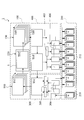
- FIG. 9 is a block diagram showing a control system of the tray transfer device in the embodiment of the present invention.
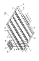
- FIG. 10 is an exploded perspective view showing a test tray used in the electronic component testing apparatus according to the embodiment of the present invention.
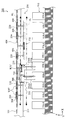
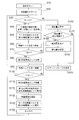
- FIG. 11 is a flowchart showing a movement error correction method according to the embodiment of the present invention.
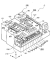
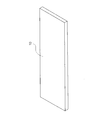
- FIG. 12 is a perspective view of a jig used when the correction method shown in FIG. 11 is executed.
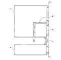
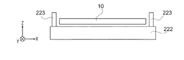
- FIG. 13A is a front view showing a state where the movable head has moved the jig to the correction target position (step S40).
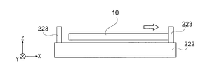
- FIG. 13B is a front view showing a state where the jig is moved to the left and brought into contact with the guide pin (step S60).
- FIG. 13C is a front view showing a state where the jig is moved to the right and is in contact with the guide pin (step S90).
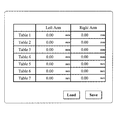
- FIG. 14 is a diagram showing a monitor screen on which coordinate values automatically corrected by the correction method shown in FIG. 11 are displayed.
- FIG. 1 is a side view showing the entire electronic component testing apparatus according to this embodiment
- FIG. 2 is a perspective view of the electronic component testing apparatus of FIG. 1
- FIG. 3 shows a tray handling method in the electronic component testing apparatus of FIG. It is a conceptual diagram.
- FIG. 3 is a view for understanding a method of handling the tray in the electronic component testing apparatus, and there is actually a portion in which the members arranged in the vertical direction are shown in a plan view. Therefore, the mechanical (three-dimensional) structure will be described with reference to FIG.
- the electronic component test apparatus tests (inspects) whether or not the IC device properly operates in a state where a high-temperature or low-temperature thermal stress is applied to the IC device, and the IC device is determined based on the test result. It is an apparatus for classifying, and includes a handler 1, a test head 5, and a tester 6. The test of the IC device by the electronic component test apparatus is performed in a state where the IC device is transferred from the customer tray KST to the test tray TST and mounted on the test tray TST.
- the customer tray KST is a tray for storing IC devices before or after the test.
- the IC device before the test is supplied to the handler 1 from the previous process while being accommodated in the customer tray KST, and the IC device that has been tested is sent out from the handler 1 to the subsequent process while being accommodated in the customer tray KST.
- the test tray TST is a dedicated tray that is circulated and conveyed in the electronic component testing apparatus.
- the handler 1 includes a storage unit 200 that stores a customer tray KST that contains a pre-test or a tested IC device, and a customer tray KST supplied from the storage unit 200.
- the IC device is mounted on the test tray TST, and the IC device is loaded in the test tray TST while applying a predetermined thermal stress to the loader unit 300 for feeding the test tray TST to the chamber unit 100 and the IC device.
- a predetermined thermal stress to the loader unit 300 for feeding the test tray TST to the chamber unit 100 and the IC device.
- an unloader unit 400 that unloads tested IC devices from the chamber unit 100 and replaces them while classifying them from the test tray TST to the customer tray KST.
- the socket 50 mounted on the top of the test head 5 is connected to the tester 6 through the cable 7 shown in FIG.
- the IC device electrically connected to the socket 50 is connected to the tester 6 via the cable 7, and a test signal is exchanged between the IC device and the tester 6.
- a space 8 is formed in the lower part of the handler 1, and the test head 5 is replaceably disposed in the space 8, and an opening formed in the main base (base) 101 of the handler 1 ( The IC device and the socket 50 on the test head 5 can be brought into electrical contact via a not-shown).
- the socket 50 on the test head 5 is replaced with a socket suitable for the type after replacement.
- ⁇ Storage unit 200> 4 and 5 are a front view and a side view showing a storage portion of the electronic component testing apparatus in the present embodiment
- FIG. 6 is an exploded perspective view showing an IC stocker used in the electronic component testing apparatus in the present embodiment
- FIG. 8 is a perspective view showing a table of a tray transfer device in this embodiment
- FIG. 9 is a control system of the tray transfer device in this embodiment. It is a block diagram.
- the storage unit 200 includes a stocker 210 that stores the customer tray KST, a lifting device 220 that can hold the customer tray KST and can be lifted, and the stocker 210 and the lifting device 220.
- a tray transfer device 230 that holds the customer tray KST and can move in the vertical direction (Z-axis direction) and the horizontal direction (X-axis direction) is provided.
- the stocker 210 includes a pre-test stocker 211 that stores a customer tray KST in which IC devices before testing are mounted, and a customer tray KST in which IC devices classified according to the test results are mounted. And a tested stocker 212 for storing.
- each of the pre-test stocker 211 and the tested stocker 212 includes a frame-like tray support frame 213 and an elevator 214 that can be moved up and down by entering from the lower portion of the tray support frame 213.
- I have.
- a plurality of customer trays KST are stacked and accommodated in the tray support frame 213, and the stacked customer trays KST are moved up and down by the elevator 214.
- the numbers of the pre-test stocker 211 and the tested stocker 212 can be appropriately set as necessary.
- one stocker STK-B is provided in the storage unit 200 as the pre-test stocker 211.
- eight stockers STK-1, STK-2,..., STK-8 are provided in the storage unit 200 as the tested stockers 212 so that they can be sorted and stored in up to eight categories according to the test results. It is configured. In other words, in addition to non-defective products and defective products, it is possible to sort non-defective products into high-speed, medium-speed, low-speed, or defective products that require retesting. It has become.
- an empty tray stocker STK-E is provided as a tested stocker 212 between STK-5 and STK-6.
- empty tray stocker STK-E empty customer trays KST to be sent to the window part 406 opened in the unloader part 400 are stacked.
- the electronic component testing apparatus in the present embodiment includes six lifting devices 220 as shown in FIG.
- the lifting device 220 has a total of six windows, two windows 306 opening in the main base 101 in the loader unit 300 and four windows 406 opening in the main base 101 in the unloader unit 400. Each one is arranged.
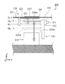
- each lifting device 220 includes a Z-axis rail 221 provided so as to hang down from the main base 101, and a table 222 provided on the Z-axis rail 211 so as to be lifted and lowered. by an actuator which, not specifically shown, the table 222 it is possible to lift between the first predetermined position H 1 and the second defined position H 2.
- First defined position H 1 is the upper limit of the Z-axis direction of the table 222, the table 222 to the first defined position H 1 is located, via the window 306 (or the window 406), customer tray The KST faces the loader unit 300 (or the unloader unit 400).
- the second defined position H 2 is the lower limit in the Z-axis direction of the table 222, in a state where the table 222 is positioned at the predetermined position of H 2 the second, customer between the tray transfer apparatus 230 The tray KST is delivered.
- the lifting device 220 moves the customer tray KST between the storage unit 200 and the loader unit 300 (or the unloader unit 400) by holding and lifting the customer tray KST on the table 222. It is possible.
- the table 222 of the lifting device 220 has four guide pins 223 for guiding the customer tray KST placed on the table 222 by the tray transfer device 230.
- the guide pins 223 are provided at the four corners of the table 222 so as to protrude upward.
- a tapered portion 223a formed of a curved surface or an inclined surface is formed at the tip of the guide pin 223 so that the customer tray KST can be easily guided.
- the tray transfer device 230 is provided on the X-axis rail 231 and the X-axis rail 231 provided along the X-axis direction between the main base 101 and the stocker 210.
- the tray transfer device 230 can grip the customer tray KST from the lowered table 222 of the lifting device 220 and move it to the stocker 210, or move the customer tray KST from the stocker 210 to the table 222 of the lifting device 220. It has become.
- the movable head 232 can be moved on the X-axis rail 231 by an X-axis motor 231a (see FIG. 9) via a ball screw mechanism (not shown). Further, as shown in FIG. 9, the X-axis motor 231a is equipped with an encoder 231b, and the detection result of the encoder 231b can be used to detect the position of the movable head 232 along the X-axis direction. It is possible.
- each holding head 234A, 234B is operated by a first and second Z-axis motors 236, 237 (see FIG. 9) via a ball screw mechanism (not shown). It is possible to move independently on 233A and 233B.
- Each holding head 234A, 234B has an open / close type gripping claw 235 for gripping the customer tray KST. In this embodiment, since the two holding heads 234A and 234B are attached to one movable head 232 via the Z-axis rails 233A and 233B, they cannot move independently in the horizontal direction. . As shown in FIG.
- first and second encoders 238 and 239 are attached to the Z-axis motors 236 and 237, respectively, and the detection results of the first and second encoders 238 and 239 are used.
- the positions of the holding heads 234A and 234B along the Z-axis direction can be detected.
- motors 231a, 236, and 237 for example, servo motors or pulse motors can be used.
- the encoders 231b, 238, and 239 for example, absolute type rotary encoders can be used.
- the motors 231a, 236, 237 and the encoders 231b, 238, 239 are connected to a control device (control computer) 240.
- the control device 240 can perform feedback control of the motors 231a, 236, and 237 using the encoders 231b, 238, and 239.
- control device 240 can set a plurality of limit torques (torque limits) for stopping the motor 231a. Furthermore, when the torque of the motor 231a reaches the limit torque, the control device 240 can detect the position at that time by the encoder 231b.
- the control unit 240, the limit torque of the motor 231a, the first and limit value t 1 for use in the correction of the movement error, the second limit value used in a normal tray transport operation t 2 It is possible to switch to.
- the first limit value t 1 is set to be smaller than the second limit value t 2 (t 1 ⁇ t 2 ).
- control device 240 stores a program for correcting the movement error of the tray transfer device 230, an internal storage device 250 for storing the corrected actual coordinate values, and the like, and stores the actual coordinate values for backup.
- the external storage device 260 is connected.
- a specific example of the internal storage device 250 is a hard disk, and a specific example of the external storage device 260 is a removable medium such as a USB memory or a floppy (registered trademark) disk.
- the control device 240 is connected to a touch panel 270 for an operator to confirm the settings of the handler 1 and input instructions.
- the tray transfer device 230 in the present embodiment has two movable positions M 1 and M 2 in the Z-axis direction that can move the holding heads 234A and 234B in the horizontal direction. have.
- the first movable position M 1 is located between the first restriction position H 1 and the second restriction position H 2 of the lifting device 220.
- the second movable position M 2 is located between the second restriction position H 2 of the lifting device 220 and the stocker 210.
- a space through which the holding heads 234A and 234B of the tray transfer device 230A can pass is formed between the stocker 210 and the table 222 located at the second restriction position H2.
- both holding heads 234A and 234B are moved in the horizontal direction while being positioned on the first movable position M 1 (or the second movable position M 2 ), or one holding head is used.
- 234A is positioned at the first movable position M 1 (or the second movable position M 2 ), and the other holding head 234B is moved to the second movable position M 2 (or the first movable position M 1).
- the holding heads 234A and 234B can be moved in the horizontal direction.
- a second movable position M 2 in the first and second holding head 234A, before testing the moved horizontally 234B stocker 211 and post-test stocker 212 above Can be moved.
- the holding heads 234A and 234B can be moved along the horizontal direction regardless of the position of the table 222 of the elevating device 220, the tray transporting operation can be shortened.
- the holding heads 234A and 234B of the tray transfer device 230 may be movable independently of each other along the X-axis direction. Further, each holding head 234A, 234B may be able to hold a plurality of customer trays KST in a stacked manner, or the table 222 of the lifting device 220 may be able to hold a plurality of customer trays KST in a stacked manner. Furthermore, in the present invention, the number of holding heads is not limited to two, and three or more holding heads may be provided. In the present invention, the number of movable positions is not limited to two, and three or more movable positions may be provided.
- FIG. 10 is an exploded perspective view showing a test tray used in the electronic component testing apparatus in the present embodiment.
- the above-described customer tray KST is transferred from the stocker 210 to the lifting device 220 by the tray transfer device 230, and further, the two window portions 360 opened to the main base 101 in the loader unit 300 by the lifting device 220. Then, it is carried from the lower side of the main base 101.
- the IC device loaded on the customer tray KST is once transferred by the device transport apparatus 310 to a precursor 305, where the mutual positional relationship of the IC devices is corrected. Thereafter, the IC device transferred to the precursor 305 is reloaded on the test tray TST stopped by the loader unit 300 by the device transport apparatus 310.
- the test tray TST has a plurality of attachments on both sides of the crosspiece 13 and on the side 12 a of the frame 12 facing the crosspiece 13.
- the pieces 14 are provided protruding at equal intervals.
- An insert accommodating portion 15 is configured by the space between the rails 13 or between the rails 13 and the side 12 a and the two attachment pieces 14.
- Each insert accommodating portion 15 can accommodate one insert 16, and this insert 16 is attached to two attachment pieces 14 in a floating state using fasteners 17. Therefore, attachment holes 19 for attaching the insert 16 to the attachment piece 14 are formed at both ends of the insert 16. As shown in FIG. 10, 64 of these inserts 16 are attached to one test tray TST, and are arranged in 4 rows and 16 columns.
- inserts 16 have the same shape and the same dimensions, and an IC device is accommodated in each insert 16.
- the IC accommodating portion 18 of the insert 16 is determined according to the shape of the IC device to be accommodated, and is a rectangular recess in the example shown in FIG.
- the loader unit 300 includes a device transfer device 310 that transfers IC devices from the customer tray KST to the test tray TST.
- the device transport apparatus 310 includes two Y-axis rails 311 that are installed on the main base 101 along the Y-axis direction, a movable rail 312 that is movable on the Y-axis rail 311 along the Y-axis direction, A movable head 313 is supported on the movable rail 312 so as to be movable along the X-axis direction, and a plurality of suction pads (not shown) provided downward on the movable head 313 are provided.
- Each suction pad can be moved up and down by an actuator (not shown), and a plurality of IC devices can be transferred from the customer tray KST to the test tray TST at a time.
- the movable rail 312 and the movable head 313 are moved by a driving force of a servo motor transmitted via, for example, a ball screw mechanism.
- a precursor 305 is provided between the customer tray KST and the test tray TST.
- the precursor 305 has a relatively deep recess, and the periphery of the recess is surrounded by an inclined surface. Therefore, the IC device to be transferred from the customer tray KST to the test tray TST is once dropped into the precursor 305 before being moved to the test tray TST, so that the mutual positional relationship between the IC devices can be accurately determined. It is possible to accurately transfer devices to the test tray TST.
- test tray TST When the IC devices are accommodated in all the accommodating portions 18 of the test tray TST, the test tray TST is carried into the chamber portion 100 by the tray transfer device 102.
- the lifting device 220 lowers the empty customer tray KST and delivers it to the tray transfer device 230.
- the tray transfer device 230 temporarily stores this empty tray in the empty tray stocker STK-E, and supplies a new empty tray to the window 406 when the customer tray KST located in the window 406 is full of IC devices. .
- test tray TST The test tray TST described above is loaded into the chamber unit 100 after the IC devices are loaded by the loader unit 300, and each IC device is tested in a state of being mounted on the test tray TST.
- the chamber unit 100 includes a soak chamber 110 that applies a target high-temperature or low-temperature heat stress to an IC device loaded on the test tray TST, and the soak chamber 110 has a heat stress.
- a test chamber 120 that presses the IC device in a state of being applied to the test head 5 and an unsoak chamber 130 that removes thermal stress from the IC device that has been tested.
- the soak chamber 110 is disposed so as to protrude upward from the test chamber 120.
- a vertical transfer device is provided in the soak chamber 110, and a plurality of test trays TST are held by the vertical transfer device until the test chamber 120 is empty. Waiting while being. Mainly, a thermal stress of about ⁇ 55 to + 150 ° C. is applied to the IC device during this standby.
- the test head 5 is disposed in the center of the test chamber 120, the test tray TST is carried above the test head 5, and the input / output terminals of the IC device are electrically connected to the contact pins of the socket 50 of the test head 5.
- the IC device is tested by bringing it into contact.
- the result of this test is stored in the storage device of the electronic component testing apparatus at an address determined by, for example, an identification number assigned to the test tray TST and an IC device number assigned in the test tray TST. .
- the unsoak chamber 130 is also disposed so as to protrude upward from the test chamber 120, and as shown conceptually in FIG. 3, a vertical transfer device is provided therein.
- the unsoak chamber 130 when a high temperature is applied to the IC device in the soak chamber 110, the IC device is cooled to the room temperature by air blowing, and then the heat-removed IC device is carried out to the unloader unit 400.
- the IC device is heated with warm air or a heater to return it to a temperature at which dew condensation does not occur, and then the removed IC device is unloaded. Carry out to 400.
- An inlet for carrying the test tray TST from the main base 101 is formed in the upper part of the soak chamber 110.
- an outlet for carrying out the test tray TST to the main base 110 is also formed in the upper part of the unsoak chamber 130.
- a tray transfer device 102 for taking the test tray TST out and in and out of the chamber section 100 through these inlets and outlets is provided on the main base 101.
- the tray transport device 102 is configured to transport the test tray TST using, for example, a rotating roller.
- the test tray TST carried out from the unsoak chamber 130 is returned to the soak chamber 110 via the unloader unit 400 and the loader unit 300 by the tray conveying device 102.
- Unloader unit 400 In the unloader unit 400, the tested IC devices are transshipped from the test tray TST carried out from the unsoak chamber 130 while being classified into customer trays according to the test results.
- four windows 406 are opened in the main base 101 in the unloader section 400.
- the customer tray KST carried from the storage portion 200 to the unloader portion 400 is disposed so as to face the upper surface of the main base 101.
- the unloader unit 400 includes two device transfer apparatuses 410 that transfer a tested IC device from the test tray TST to the customer tray KST. Similar to the device transport apparatus 310 of the loader unit 300, the device transport apparatus 410 includes a Y-axis rail 411, a movable rail 412, and a movable head 413, and a plurality of IC devices are transferred from the test tray TST to the customer tray KST. It is possible to transship at the same time.
- an elevating device 220 is provided below each window 406 to elevate and lower the customer tray KST.
- the customer tray KST which has been loaded with the tested IC devices, is loaded and lowered, and the tray transfer device 230 receives the full tray.
- the tray transfer device 230 transfers the full tray to the tested stocker 212 according to the test result.
- the four window portions 406 are formed in the unloader portion 400, the four categories (test results) can be classified in real time.
- four categories with high occurrence frequency are always located in the window 406, and categories with low occurrence frequency are temporarily stored in the buffer unit 405 (see FIG. 3).
- the customer tray KST corresponding to the category may be called to the window unit 406.
- FIG. 11 is a flowchart showing a movement error correction method according to this embodiment
- FIG. 12 is a perspective view of a jig used when executing the correction method shown in FIG. 11, and
- FIGS. 13A to 13C are flowcharts shown in FIG.
- FIG. 14 is a diagram showing a monitor screen on which actual coordinate values automatically calculated by the correction method shown in FIG. 11 are displayed.
- step S10 When the operator holds the jig 10 on both holding heads 234A and 234B of the tray transfer device 230 (step S10 in FIG. 11) and presses a start button (not shown) displayed on the touch panel 270, the tray transfer device 230 The correction of the movement error is started (step S20).
- the jig 10 used for correcting the movement error has the same outer shape (contour) as the customer tray KST except that the accommodating portion 91 is not formed.
- the jig 10 is made of, for example, a metal material and is not deformed when pressed against the guide pin 233.
- control device 240 confirms whether or not there is a correction target position where the movement error is to be corrected (step S30). Specifically, control device 240 counts the number (N) of correction target positions that have already been corrected, and when the count reaches the total number of correction target positions (NO in step S30). End correction. For example, in this embodiment, since there are six tables 222 and two holding heads 234A and 234B, a total of twelve corrections are performed.
- the control device 240 performs, for example, one gripping head 234A for the first correction as shown in FIG. 13A.
- the tray transfer device 230 is controlled so as to be moved to the target position (step S40).
- the correction target position is the position (mounting position) of the holding head 234A or 234B immediately before the customer tray KST is delivered to the table 222.
- the holding head 234A of the tray transfer device 230 moves to the coordinates before correction.
- the coordinates before correction are the coordinate values set at the initial stage if the correction is performed when the handler 1 is completed, and the coordinates corrected previously when the correction has already been performed. .
- step S50 the control unit 240, the limit torque of the X-axis motor 231a of the tray transfer apparatus 230 is switched from the second limit torque value t 2 to the first limit torque value t 1 (step S50).
- control device 240 moves the holding head 234A leftward in the figure as shown in FIG. 13B while detecting the torque of the X-axis motor 231a (step S60).
- the torque of the X-axis motor 231a is detected based on, for example, a current value output from the X-axis motor 231a.
- Step S80 Controller 240 until the torque T of the X-axis motor 231a reaches the first limit value T 1.
- the control unit 240 stops the X-axis motor 231a, the detection result of the encoder 231b based on, the torque T was calculated X-coordinate value of the holding head 234A at the moment of reaching the first limit value t 1, it is stored in the internal storage device 250 to the coordinate value as a first boundary point (step S80 ). Note that by the jig 10 abuts against the guide pin 223 shown in the left side in FIG. 13B, the torque T of the X-axis motor 231a reaches the first limit value T 1.
- control device 240 moves the holding head 234A to the right in the drawing as shown in FIG. 13C while detecting the torque of the X-axis motor 231a (step S90).
- Controller 240 until the torque T of the X-axis motor 231a reaches the first limit value t 1, to continue the rightward movement of the holding head 234A (NO in step S100: T ⁇ t 1).
- the control unit 240 stops the X-axis motor 231a, the detection result of the encoder 231b based on, the torque T was calculated X-coordinate value of the holding head 234A at the moment of reaching the first limit value t 1, it is stored in the internal storage device 250 to the coordinate value as a second boundary point (step S110 ).
- control device 240 calculates the actual coordinate value of the correction target position based on the first boundary point stored in step S80 and the second boundary point stored in step S110 (step S120). ). Specifically, in the present embodiment, the midpoint of the first boundary point and the second boundary point is calculated as an actual coordinate value. Then, the control device 240 registers the actual coordinate value calculated in step S120 as the corrected coordinate value of the correction target position (step S130).
- control device 240 may calculate correction amounts for all the correction target positions and register the correction amounts as in step S160 described later. This correction amount cancels out the movement error generated in the tray transfer device 230.
- steps S60 to S110 are repeated a plurality of times to store a plurality of first boundary points and a plurality of second boundary points.
- steps S60 to S110 are repeated a plurality of times to store a plurality of first boundary points and a plurality of second boundary points.
- steps S120 these average values are calculated. It may be calculated as an actual coordinate value.
- step S30 the control device 240 determines whether or not the number of correction target positions that have already been corrected has reached the total number of correction target positions. In step S30, when the count number of the correction target positions that have already been corrected does not reach the total number (YES in step S30: N ⁇ 12), the movement error is corrected at the next correction target position. Do.
- step S160 the control device 240 obtains a correction amount by obtaining a difference between the coordinate value of the correction target position (coordinate value before correction) used in step S40 and the actual coordinate value calculated in step S120. calculate. This correction amount is obtained for each of all correction target positions.
- control device 240 determines whether or not each correction amount is within a predetermined range (step S170). If all the correction amounts are within the predetermined range (YES in step S170), control device 240 causes touch panel 270 to display corrected holding heads 234A and 234B at each correction target position, as shown in FIG.
- the coordinate value (actual coordinate value) is displayed (step S180). In addition to the actual coordinate value, the correction amount at each correction target position may be displayed on the touch panel 270.
- step S190 when the operator presses the “save” button on the touch panel 270, the coordinate values after the automatic correction are stored in the storage devices 250 and 260, respectively.
- control device 170 displays an error message on touch panel 270 or generates a warning sound, for example, to the operator. On the other hand, it is alerted that the automatic correction has failed (step S200). Based on this warning, the operator checks the tray transfer device 230 and the like.
- a program for causing the control device 240 of the tray transfer device 230 to execute the correction method described above is stored in the internal storage device 250 shown in FIG.
- the actual coordinate value of the correction target position is based on the first boundary point and the second boundary point detected by moving the jig 10 left and right by the tray transfer device 230. Is calculated. Thereby, since the movement error of the tray transfer device can be automatically corrected, the correction accuracy can be made constant and the productivity can be improved.
- two boundary points are detected in obtaining the actual coordinate value of the correction target position.
- the present invention is not particularly limited to this, and correction is performed based on three or more boundary points.
- the actual coordinate value of the target position may be obtained.
- the present invention is not particularly limited to this.
- the movement error of the holding head along the XY direction may be corrected.
- the present invention is not particularly limited to this.
- the movement error of the tray transfer device 230 that occurs with respect to the stocker 210 may be corrected.
- the tray transfer device 230 causes the jig 10 held by the holding heads 234A and 234B to abut on the tray support frame (frame) 213 of the stocker 210, so that the first and second boundary points are obtained. Is detected.
Landscapes
- Engineering & Computer Science (AREA)
- Computer Hardware Design (AREA)
- Microelectronics & Electronic Packaging (AREA)
- General Engineering & Computer Science (AREA)
- Physics & Mathematics (AREA)
- General Physics & Mathematics (AREA)
- Testing Of Individual Semiconductor Devices (AREA)
Abstract
L'invention concerne un procédé de correction comprenant une étape de transfert pour transférer un gabarit de montage (10) à une position cible de correction au moyen d'un dispositif de transfert de plateau (230) ; une première étape de recherche pour déplacer le gabarit de montage (10) dans une première direction, tout en mesurant un couple moteur selon l'axe X (231a) ; une première étape de stockage pour stocker une position, où un couple T du moteur (231a) dépasse une première valeur de limitation t1, en tant que premier point frontière ; une seconde étape de recherche pour déplacer le gabarit de montage (10) dans une seconde direction, tout en mesurant un couple moteur (231a) ; une seconde étape de stockage pour stocker une position, où un couple T du moteur (231a) dépasse une première valeur de limitation t1, en tant que second point frontière ; une étape de calcul pour calculer des coordonnées réelles à partir des premier et second points frontière.
Priority Applications (1)
| Application Number | Priority Date | Filing Date | Title |
|---|---|---|---|
| PCT/JP2008/052745 WO2009104247A1 (fr) | 2008-02-19 | 2008-02-19 | Procédé de correction d'erreur de déplacement de dispositif de transfert de plateau et programme de correction |
Applications Claiming Priority (1)
| Application Number | Priority Date | Filing Date | Title |
|---|---|---|---|
| PCT/JP2008/052745 WO2009104247A1 (fr) | 2008-02-19 | 2008-02-19 | Procédé de correction d'erreur de déplacement de dispositif de transfert de plateau et programme de correction |
Publications (1)
| Publication Number | Publication Date |
|---|---|
| WO2009104247A1 true WO2009104247A1 (fr) | 2009-08-27 |
Family
ID=40985142
Family Applications (1)
| Application Number | Title | Priority Date | Filing Date |
|---|---|---|---|
| PCT/JP2008/052745 Ceased WO2009104247A1 (fr) | 2008-02-19 | 2008-02-19 | Procédé de correction d'erreur de déplacement de dispositif de transfert de plateau et programme de correction |
Country Status (1)
| Country | Link |
|---|---|
| WO (1) | WO2009104247A1 (fr) |
Citations (1)
| Publication number | Priority date | Publication date | Assignee | Title |
|---|---|---|---|---|
| JP2007198903A (ja) * | 2006-01-26 | 2007-08-09 | Seiko Epson Corp | 搬送装置の位置調整方法、搬送装置の位置調整装置及びicハンドラー |
-
2008
- 2008-02-19 WO PCT/JP2008/052745 patent/WO2009104247A1/fr not_active Ceased
Patent Citations (1)
| Publication number | Priority date | Publication date | Assignee | Title |
|---|---|---|---|---|
| JP2007198903A (ja) * | 2006-01-26 | 2007-08-09 | Seiko Epson Corp | 搬送装置の位置調整方法、搬送装置の位置調整装置及びicハンドラー |
Similar Documents
| Publication | Publication Date | Title |
|---|---|---|
| JP3951436B2 (ja) | Ic試験装置 | |
| CN110023773B (zh) | 测试系统 | |
| US11346861B2 (en) | Contact accuracy assurance method, contact accuracy assurance mechanism, and inspection apparatus | |
| JPH10148507A (ja) | 水平搬送テストハンドラ | |
| WO2004106945A2 (fr) | Dispositif d'essai de partie electronique | |
| TWI518339B (zh) | 用以測試電子裝置之測試系統及方法 | |
| KR20210111681A (ko) | 검사 장치 | |
| JPWO2008139853A1 (ja) | 電子部品試験装置、電子部品試験システム及び電子部品の試験方法 | |
| KR20180017594A (ko) | 반도체 소자 테스트 장치 | |
| US20200158775A1 (en) | Inspection system | |
| KR101838805B1 (ko) | 반도체 소자 테스트 장치 및 방법 | |
| JP4222442B2 (ja) | 電子部品試験装置用インサート | |
| JP4570208B2 (ja) | 試験済み電子部品の分類制御方法 | |
| JP5469183B2 (ja) | 負荷の下で基板を検査する装置 | |
| TWI759545B (zh) | 檢測系統及檢測方法 | |
| US20090314607A1 (en) | Electronic device conveying method and electronic device handling apparatus | |
| US11474147B2 (en) | Kit-less pick and place handler system for thermal testing | |
| JPS62263647A (ja) | ウエハプロ−バ | |
| JP2008008895A (ja) | 半導体デバイスの検査装置および半導体デバイスの検査方法 | |
| WO2009116165A1 (fr) | Dispositif de transport de plateaux et dispositif d'essai de pièces électroniques équipé de ce dispositif de transport de plateaux | |
| JP5022375B2 (ja) | トレイ搬送装置及びそれを備えた電子部品試験装置 | |
| TW202235884A (zh) | 檢查裝置之設定方法及檢查裝置 | |
| JP5314668B2 (ja) | 電子部品移載装置およびそれを備えた電子部品試験装置 | |
| KR20050089107A (ko) | 반도체 소자 테스트 핸들러의 픽커의 작업위치 인식 장치및 방법 | |
| JPH02281101A (ja) | 半導体検査装置 |
Legal Events
| Date | Code | Title | Description |
|---|---|---|---|
| 121 | Ep: the epo has been informed by wipo that ep was designated in this application |
Ref document number: 08711569 Country of ref document: EP Kind code of ref document: A1 |
|
| NENP | Non-entry into the national phase |
Ref country code: DE |
|
| 122 | Ep: pct application non-entry in european phase |
Ref document number: 08711569 Country of ref document: EP Kind code of ref document: A1 |
|
| NENP | Non-entry into the national phase |
Ref country code: JP |