WO2009104434A1 - 輪転印刷機 - Google Patents
輪転印刷機 Download PDFInfo
- Publication number
- WO2009104434A1 WO2009104434A1 PCT/JP2009/050369 JP2009050369W WO2009104434A1 WO 2009104434 A1 WO2009104434 A1 WO 2009104434A1 JP 2009050369 W JP2009050369 W JP 2009050369W WO 2009104434 A1 WO2009104434 A1 WO 2009104434A1
- Authority
- WO
- WIPO (PCT)
- Prior art keywords
- blanket
- plate
- cylinder
- width
- web
- Prior art date
- Legal status (The legal status is an assumption and is not a legal conclusion. Google has not performed a legal analysis and makes no representation as to the accuracy of the status listed.)
- Ceased
Links
Images


Classifications
-
- B—PERFORMING OPERATIONS; TRANSPORTING
- B41—PRINTING; LINING MACHINES; TYPEWRITERS; STAMPS
- B41N—PRINTING PLATES OR FOILS; MATERIALS FOR SURFACES USED IN PRINTING MACHINES FOR PRINTING, INKING, DAMPING, OR THE LIKE; PREPARING SUCH SURFACES FOR USE AND CONSERVING THEM
- B41N10/00—Blankets or like coverings; Coverings for wipers for intaglio printing
- B41N10/02—Blanket structure
-
- B—PERFORMING OPERATIONS; TRANSPORTING
- B41—PRINTING; LINING MACHINES; TYPEWRITERS; STAMPS
- B41F—PRINTING MACHINES OR PRESSES
- B41F13/00—Common details of rotary presses or machines
- B41F13/08—Cylinders
- B41F13/10—Forme cylinders
-
- B—PERFORMING OPERATIONS; TRANSPORTING
- B41—PRINTING; LINING MACHINES; TYPEWRITERS; STAMPS
- B41F—PRINTING MACHINES OR PRESSES
- B41F13/00—Common details of rotary presses or machines
- B41F13/08—Cylinders
- B41F13/193—Transfer cylinders; Offset cylinders
-
- B—PERFORMING OPERATIONS; TRANSPORTING
- B41—PRINTING; LINING MACHINES; TYPEWRITERS; STAMPS
- B41F—PRINTING MACHINES OR PRESSES
- B41F27/00—Devices for attaching printing elements or formes to supports
- B41F27/12—Devices for attaching printing elements or formes to supports for attaching flexible printing formes
- B41F27/1218—Devices for attaching printing elements or formes to supports for attaching flexible printing formes comprising printing plate tensioning devices
-
- B—PERFORMING OPERATIONS; TRANSPORTING
- B41—PRINTING; LINING MACHINES; TYPEWRITERS; STAMPS
- B41F—PRINTING MACHINES OR PRESSES
- B41F30/00—Devices for attaching coverings or make-ready devices; Guiding devices for coverings
- B41F30/04—Devices for attaching coverings or make-ready devices; Guiding devices for coverings attaching to transfer cylinders
-
- B—PERFORMING OPERATIONS; TRANSPORTING
- B41—PRINTING; LINING MACHINES; TYPEWRITERS; STAMPS
- B41N—PRINTING PLATES OR FOILS; MATERIALS FOR SURFACES USED IN PRINTING MACHINES FOR PRINTING, INKING, DAMPING, OR THE LIKE; PREPARING SUCH SURFACES FOR USE AND CONSERVING THEM
- B41N2210/00—Location or type of the layers in multi-layer blankets or like coverings
- B41N2210/02—Top layers
-
- B—PERFORMING OPERATIONS; TRANSPORTING
- B41—PRINTING; LINING MACHINES; TYPEWRITERS; STAMPS
- B41N—PRINTING PLATES OR FOILS; MATERIALS FOR SURFACES USED IN PRINTING MACHINES FOR PRINTING, INKING, DAMPING, OR THE LIKE; PREPARING SUCH SURFACES FOR USE AND CONSERVING THEM
- B41N2210/00—Location or type of the layers in multi-layer blankets or like coverings
- B41N2210/04—Intermediate layers
-
- B—PERFORMING OPERATIONS; TRANSPORTING
- B41—PRINTING; LINING MACHINES; TYPEWRITERS; STAMPS
- B41N—PRINTING PLATES OR FOILS; MATERIALS FOR SURFACES USED IN PRINTING MACHINES FOR PRINTING, INKING, DAMPING, OR THE LIKE; PREPARING SUCH SURFACES FOR USE AND CONSERVING THEM
- B41N2210/00—Location or type of the layers in multi-layer blankets or like coverings
- B41N2210/10—Location or type of the layers in multi-layer blankets or like coverings characterised by inorganic compounds, e.g. pigments
Definitions
- the present invention relates to a rotary printing press that performs printing on a conveyed web by rotating a blanket cylinder and a plate cylinder.
- a conventional rotary printing machine includes a blanket cylinder that is in contact with a conveyed web and a plate cylinder that is in contact with the blanket cylinder (see, for example, Patent Document 1).
- the conventional rotary printing press is a so-called 4 (W) ⁇ 2 (L) rotary printing press, and the diameter of the blanket cylinder and the plate cylinder of the rotary printing press are the same.
- the cylinder width W in the axial direction of the plate cylinder is equivalent to the page width of the printed page printed on the web
- the outer peripheral length L in the circumferential direction of the plate cylinder is equivalent to two pages of the page length of the printed page printed on the web.
- Such a conventional rotary printing press is suitable for printing a large number of printed materials at a high speed.
- the printing plate wound around the plate cylinder of the rotary printing press has been replaced without reaching the service life.
- the printing amount printed by the rotary printing press is small, the number of times of use of the printing plate is small, and the plate is replaced before reaching the service life of the printing plate.
- the outer peripheral length L in the circumferential direction of the plate cylinder is one page of the page length of the printed page printed on the web.
- a 4 (W) ⁇ 1 (L) rotary printing press is used. Accordingly, the outer peripheral length of the plate cylinder in the 4 (W) ⁇ 1 (L) rotary printing press is halved compared to the outer peripheral length of the plate cylinder in the 4 (W) ⁇ 2 (L) rotary printing press. Therefore, the number of times the printing plate is used can be doubled, and the printing plate can be used without waste.
- the plate cylinder becomes an elongated cylinder (long cylinder), and the rigidity of the plate cylinder decreases, so that the plate cylinder is more easily bent than in the past. End up.
- the plate cylinder is easily bent, for example, the plate cylinder is easily affected by a gap formed in the plate cylinder or the blanket cylinder.
- the gap is an opening width of a groove for fixing a printing plate wound around a plate cylinder or a blanket wound around a blanket cylinder.
- the plate cylinder is rotated by being brought into contact with the blanket cylinder while the gap of the blanket cylinder and the gap of the plate cylinder are opposed to each other.
- the present invention has an object to provide a rotary printing press capable of stably performing printing in the entire speed range while maintaining printing quality even when the plate cylinder becomes a long cylinder and rigidity is reduced.
- the rotary printing press of the present invention is a rotary printing press capable of printing on a web by rotating a blanket cylinder that is in contact with the web to be conveyed and a plate cylinder that is in contact with the blanket cylinder. Formed over the entire body width along the axial direction on the outer circumference of the wound plate cylinder body and the plate cylinder body. The plate is inserted into the plate insertion groove, and the plate end inserted into the plate insertion groove is locked to the plate cylinder body.
- the plate cylinder body is configured such that the W / L obtained by dividing the cylinder width W in the axial direction by the outer circumferential length L in the circumferential direction is 1.6 or more.
- a first locking portion that is provided in the groove and locks the grip-side end inserted in the plate insertion groove, and in the plate insertion groove
- a tension bar that extends in the axial direction of the plate cylinder main body and is rotatably provided, and has a second locking portion that locks the tail edge end portion inserted into the plate insertion groove.
- the blanket cylinder is formed along the axial direction on the outer peripheral surface of the blanket cylinder body and the blanket cylinder body with the blanket wound around the outer periphery.
- Blanket insertion groove that can be inserted into the end, and blanket that can be clamped and secured to the blanket cylinder body by locking the end of the blanket inserted into the blanket insertion groove and the end of the end of the blanket And a blanket having a metal layer on the inner peripheral side in the wound state and a blanket layer on the outer peripheral side in the wound state.
- the plate cylinder is provided with a cocking device capable of adjusting the one end side of the plate cylinder in the ascending / descending direction perpendicular to the separation / attachment direction of the blanket cylinder.
- another rotary printing press of the present invention is a rotary printing press capable of printing on a web by rotating a blanket cylinder that is in contact with the web to be conveyed and a plate cylinder that is in contact with the blanket cylinder.
- a plate cylinder body on which a printing plate is wound, and an outer peripheral surface of the plate cylinder body that is formed over the entire cylinder width along the axial direction, and at the edge side and the tail edge side of the printing plate The plate is inserted into the plate cylinder and the plate end is inserted into the plate insertion groove, and the plate end inserted into the plate insertion groove is engaged with the end of the plate end.
- a plate clamping device, and a cocking device capable of adjusting one end side of the plate cylinder in an ascending / descending direction perpendicular to the direction of separation of the blanket cylinder with respect to the blanket cylinder.
- W / L obtained by dividing W by outer circumferential length L in the circumferential direction is configured to be 1.6 or more. And said that you are.
- the blanket cylinder is formed along the axial direction on the outer peripheral surface of the blanket cylinder main body with the blanket wound around the outer periphery, and at the end of the blanket and the tail end of the blanket
- the blanket can be inserted into the blanket insertion groove, and the blanket can be fastened to the blanket body by locking the blanket insertion end and the tail end of the blanket inserted in the blanket insertion groove.
- the blanket has a metal layer on the inner peripheral side in the wound state and a blanket layer on the outer peripheral side in the wound state.
- the cocking apparatus has an eccentric bearing that supports one end side of the rotation axis of the plate cylinder and a rotation mechanism that rotates the eccentric bearing around the rotation axis.
- the rotation mechanism includes a cocking drive source for rotating the eccentric bearing, and the cocking device has a cocking control means for controlling the cocking drive source.
- a width register correcting device provided to face the conveyed web and restore the web stretched in the width direction is provided.
- the width register correcting device also includes a roller group in which a plurality of rollers capable of rolling contact with the web being conveyed are provided in the width direction of the web, and a roller group separation unit for moving the roller group back and forth in the web separation / contact direction. It is preferable to have a contact mechanism.
- the roller group separating / attaching mechanism includes a width register correcting drive source for moving the roller group forward and backward in the separating direction, and the width register correcting device controls the width register correcting drive source. It is preferable to have a control means.
- the width register correcting device is provided with a nozzle group in which a plurality of spray nozzles capable of spraying air on the web to be conveyed are provided in the width direction of the web, and the nozzle group through the air supply flow path. It is preferable to have an air supply means capable of supplying air.
- a plurality of print pages of a predetermined size having a predetermined page width and a predetermined page length are printed on the web after printing in the web conveyance direction and the width direction.
- the body width in the axial direction is configured to be four pages of the page width
- the outer peripheral length in the circumferential direction is configured to be one page of the page length.
- the blanket cylinder is formed along the axial direction on the outer peripheral surface of the blanket cylinder main body with two blankets wound around the outer periphery, and at the end of each blanket And two blanket insertion grooves into which the tail edge side end can be inserted, and the blanket cylinder body is configured such that the cylinder width in the axial direction of the blanket cylinder is equal to four pages of the page width.
- the outer peripheral length in the circumferential direction of the cylinder is configured to be two pages of the page length, and the two blanket insertion grooves are respectively formed in half the cylinder width of the blanket cylinder body, and the blanket cylinder body
- the blanket insertion groove is formed close to one end side of the blanket cylinder body, and the other Blanket insertion groove, it is preferably formed closer to the other end of the blanket cylinder body.
- the printing side end portion and the tail end side end portion of the printing plate wound around the plate cylinder main body are formed over the entire cylinder width of the plate cylinder main body.
- the plate can be inserted into the plate insertion groove and the plate can be clamped and fixed by a plate clamping device.
- the plate insertion groove can be formed in a straight line over the entire cylinder width of the plate cylinder main body, so that the grooving is performed with high accuracy. It can be performed.
- the plate end side and the tail edge side end of the printing plate are locked to the first locking portion and the second locking portion, and the plate is printed by rotating the tension bar. It is configured to be fastened and fixed to the cylinder body.
- the tip structure of the second locking portion that holds the tail edge side end portion of the printing plate is formed into an acute shape, thereby The bending margin at the tail edge side end can be reduced, and it is not necessary to increase the groove opening width (gap) of the printing plate insertion groove, and the gap can be reduced as much as possible.
- the inner peripheral side of the blanket wound around the blanket cylinder body is a metal layer, only the blanket metal layer needs to be inserted into the blanket insertion groove, so the groove opening of the blanket insertion groove There is no need to increase the width (gap), and the gap can be made as small as possible. Thereby, the gap of the plate cylinder and the gap of the blanket cylinder can be made as small as possible. At this time, the smaller the gap, the smaller the impact generated when passing through the gap. In other words, the plate cylinder can be smoothly brought into contact with the blanket cylinder. Can be reduced. Thereby, it is possible to suppress the occurrence of a light and dark stripe pattern (shock eyes) on the printed web due to the vibration of the plate cylinder.
- the gap of the blanket cylinder is preferably configured to be somewhat larger than the gap of the plate cylinder. According to this, even if ink adheres to the inside of the plate cylinder gap, the blanket cylinder gap faces the ink adhesion portion, so that the ink adhered to the plate cylinder gap is transferred to the blanket cylinder. Can be suppressed. Further, as the plate cylinder in which W / L is 1.6 or more, for example, 4 (W) ⁇ 1 (L), 6 (W) ⁇ 2 (L), and 8 (W) ⁇ 2 (L) There are plate cylinders used in rotary printing presses such as.
- the one end side of the plate cylinder can be moved up and down with respect to the blanket cylinder by the cocking device. Can be made.
- the plate cylinder is not properly rolled against the blanket cylinder due to mechanical errors or mounting errors, and printing misalignment occurs on the web, one end of the plate cylinder is adjusted in the up-and-down direction by the cocking device. By doing so, it is possible to correct printing misalignment (registered twist) on the web, and it is possible to appropriately print on the web.
- the inner peripheral side of the blanket wound around the blanket cylinder main body is a metal layer, only the blanket metal layer needs to be inserted into the blanket insertion groove. It is not necessary to increase the groove opening width (gap) of the insertion groove, and the gap can be reduced. As a result, the plate cylinder is not easily affected by the gap, and the vibration of the plate cylinder can be reduced. Therefore, the vibration of the plate cylinder causes a light and dark stripe pattern (shock eyes) to occur on the printed web. Can be suppressed.
- the cocking device can be simplified.
- the cocking drive source can be controlled by the cocking control means, the cocking device can be remotely operated.
- the misalignment registered twist
- the misprinting on the web can be performed without stopping the rotary printing press by remotely operating the cocking device. It becomes possible to correct (the top and bottom register misalignment and register twist).
- the web misalignment correction device can restore the web to the original width. (Fan-out) can be corrected, and printing on the web can be performed well.
- a plurality of convex surfaces can be formed on the web by abutting the roller group against the web by the roller group separation / contact mechanism.
- the width register correcting device can be controlled by the width register correcting control means, it is possible to remotely operate the width register correcting device without stopping the rotary printer. It is possible to correct misregistration (fanout).
- the rotary printing press of claim 10 it is possible to form a plurality of convex surfaces on the web by blowing air from the nozzle group onto the web.
- stretched in the width direction can be decompress
- the plate cylinder can be a 4 (W) ⁇ 1 (L) plate cylinder, and the rotary printing press can be configured for small lot printing.
- the blanket cylinder is balanced. Can be good.
- FIG. 1 is a schematic diagram illustrating a newspaper offset rotary printing press according to the present embodiment.
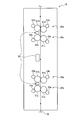
- FIG. 2 is a schematic diagram showing a multicolor printing apparatus.
- FIG. 3 is a schematic diagram schematically showing a plate cylinder and a blanket cylinder.
- FIG. 4 is an external perspective view showing the plate cylinder body and the blanket cylinder body.
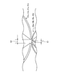
- FIG. 5 is a side view showing the periphery of the cocking device.
- FIG. 6 is an explanatory diagram regarding the gap of the plate cylinder and the gap of the blanket cylinder.
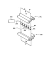
- FIG. 7 is an external perspective view showing the width register correcting device.
- FIG. 8 is an external perspective view showing a width register correcting device according to a modification.
- FIG. 1 is a schematic view showing a newspaper offset rotary printing press to which the rotary printing press of this embodiment is applied
- FIG. 2 is a schematic view showing a multicolor printing apparatus
- 3 is a schematic view schematically showing the plate cylinder and the blanket cylinder
- FIG. 4 is an external perspective view showing the plate cylinder body and the blanket cylinder body
- 5 is a side view showing the periphery of the cocking apparatus
- FIG. 6 is an explanatory diagram regarding the gap of the plate cylinder and the gap of the blanket cylinder.
- FIG. 7 is an external perspective view showing a width register correcting device
- FIG. 8 is an external perspective view showing a width register correcting device according to a modification.
- a newspaper offset rotary printing press 10 applied as a rotary printing press includes a plurality of paper feeding devices 11, a printing device 12, a paper transport device 13, and a folding machine 14. It consists of and.
- Each paper feeding device 11 is provided with a holding arm 15 for holding three webs R each having a web W wound in a roll shape, and the webs R are fed by rotating the holding arms 15. You can face the position.
- Each paper feeding device 11 is provided with a paper splicing device (not shown), and when the web R fed out at the paper feeding position becomes small, the paper splicing device causes the paper web R at the paper feeding position to be removed. Thus, the web R in the standby position can be spliced.
- the printing apparatus 12 is provided with a multi-color printing apparatus 16 that performs double-sided four-color printing and a two-color printing apparatus 17 that performs double-sided two-color printing.
- the multi-color printing device 16 and the two-color printing device 17 can perform predetermined printing on the web W supplied from each paper feeding device 11.
- the printing apparatus 12 includes the multi-color printing apparatus 16 and the two-color printing apparatus 17, but the present invention is not limited to this structure.
- various printing apparatuses may be used in combination as appropriate according to the printed matter, such as a double-sided monochrome printing apparatus that performs double-sided monochrome printing and a multicolor printing apparatus that performs 4-color or 2-color printing on one side.
- the paper transport device 13 includes a plurality of cutters that cut along the transport direction of the web W at the center in the width direction of the web W and a number of guide rollers that set the transport path of the cut web W.
- a turn bar, a slitter device, and the like are provided. Accordingly, the webs W printed by the printing device 12 are cut by the paper conveying device 13 by the cutter, and the conveying path is changed by the turn bar so that they can be overlapped in a predetermined order.
- the folding machine 14 overlaps and vertically folds a plurality of webs W fed from the paper transport device 13, and cuts the paper W by a predetermined length, and then horizontally folds to form a desired folding book and then discharges the paper. It is.
- the printing apparatus 12 will be described in detail with reference to FIG.
- the multicolor printing apparatus 16 will be described as an example of the printing apparatus 12.
- the multi-color printing device 16 is composed of four printing units 20a, 20b, 20c, and 20d for each of the four ink colors Cyan, Magenta, yellow, and black.
- the four printing units 20a, 20b, 20c, and 20d are arranged in the order of the indigo printing unit 20a, the red printing unit 20b, the yellow printing unit 20c, and the black printing unit 20d from the upstream side in the conveyance direction of the web W. It is arranged.
- the arrangement order of the printing units 20a, 20b, 20c, and 20d is not limited to this, and may be a desired arrangement order.
- Each of the printing units 20a, 20b, 20c, and 20d is configured to be able to print on the front and back surfaces of the web W at the same time.
- the web W is printed by each of the printing units 20a, 20b, 20c, and 20d, so that a print page of a predetermined size having a predetermined page width and a predetermined page length is formed on both sides of the printed web W.
- a plurality of prints are performed across the conveyance direction of the web W and the width direction of the web W.
- Each printing unit 20a, 20b, 20c, 20d includes a pair of blanket cylinders 21a, 21b, 21c, 21d facing each other across the web W, and a pair of plate cylinders 23a in contact with the blanket cylinders 21a, 21b, 21c, 21d. , 23b, 23c, and 23d.
- the pair of blanket cylinders 21a in the indigo printing unit 20a and the pair of blanket cylinders 21b in the red printing unit 20b are disposed close to each other.
- a pair of blanket cylinders 21d in the printing unit 20d are arranged close to each other.
- the plate cylinder 23 a includes a plate cylinder main body 30, four printing plates 31 wound around the outer periphery of the plate cylinder main body 30, and a plate insertion groove 32 formed on the outer peripheral surface of the plate cylinder main body 30 along the axial direction. And a plate clamping device 33 capable of clamping and fixing each printing plate 31 to the plate cylinder main body 30.
- the plate cylinder main body 30 has a rotation shaft 35 at its axis, and the rotation shaft 35 is supported at one end side 35a by a double eccentric bearing 51 (see FIG. 5) described later and at the other end.
- the side 35b is pivotally supported by a single eccentric bearing described later.
- the plate cylinder main body 30 can be rotated by a driving device (not shown).
- the plate cylinder body 30 has a cylinder width W in the axial direction corresponding to four pages of the page width of the printed page, and an outer peripheral length L in the circumferential direction of one page length of the printed page. It has become. That is, the plate cylinder main body 30 is configured to have a size of 4 (W) ⁇ 1 (L). At this time, W / L obtained by dividing the trunk width W by the outer peripheral length L is 1.6 or more. In addition, the cylinder whose W / L is 1.6 or more is a long cylinder.
- the printing plates 31 wound around the plate cylinder main body 30 are configured to have the same size as the size of the print page, and the four printing plates 31 are wound side by side in the axial direction of the plate cylinder main body 30. That is, four printing pages are transferred in the axial direction of the blanket cylinder 21a by performing one rotation of the plate cylinder 23a.
- the plate insertion groove 32 formed in the plate cylinder body 30 is formed in a straight line over the entire cylinder width of the plate cylinder body 30. For this reason, when the groove is formed in the plate cylinder body 30 to form the plate insertion groove 32, the plate insertion groove 32 may be formed in a straight line over the entire cylinder width of the plate cylinder body 30.
- the groove can be well processed. The plate-side end 37 and the tail-end side 38 of each plate 31 are inserted into the plate insertion groove 32.
- the plate clamping device 33 is formed in the printing plate insertion groove 32 and has a locking groove 40 (first locking portion) for locking the grip-side end portion 37 of each printing plate 31, and the printing plate insertion.
- a tension bar 41 extending in the axial direction of the plate cylinder main body 30 in the groove 32 and rotatably provided.
- the locking groove 40 is formed in the vicinity of the opening of the printing plate insertion groove 32, and the angle formed between the locking groove 40 and the outer peripheral surface of the plate cylinder body 30 is an acute angle. At this time, since the tail end 37 of each printing plate 31 is formed to be bent, when the tail end 37 of each printing plate 31 is inserted into the locking groove 40, each printing plate 31. The grip-side end portion 37 is caught in the locking groove 40, whereby the grip-side end portion 37 of each printing plate 31 is locked.
- the tension bar 41 has a rotating shaft 42 at its axis and is configured to be rotatable. Further, a locking claw 43 (second locking portion) formed by bending in the winding direction of each printing plate 31 is formed on the outer peripheral portion of the tension bar 41, and the distal end portion of the locking claw 43 is formed. Has an acute angle. Then, the tail edge side end portion 38 of each printing plate 31 is locked to the locking claw 43.
- the plate clamping device 33 When the printing plate 31 is fixed to the plate cylinder body 30 by the plate clamping device 33, first, the grip-side end portion 37 of the printing plate 31 is inserted into the locking groove 40 and locked. Subsequently, the plate cylinder body 30 is rotated to wind the printing plate 31 around the plate cylinder body 30, and then the tail edge side end portion 38 of the printing plate 31 is locked to the locking claw 43. By rotating the bar 41 in the fastening direction, the printing plate 31 can be fastened and fixed to the plate cylinder main body 30. According to such a plate clamping device 33, since the locking claw 43 has an acute structure, the bending margin at the tail edge side end portion of the printing plate 31 can be reduced, so that the groove opening of the printing plate insertion groove 32 can be reduced.
- the width (gap G1: see FIG. 6) can be made as small as possible. For example, the gap G1 can be about 2 mm.
- a cocking device 50 is provided on the plate cylinder 23a.
- the cocking device 50 raises and lowers one end side of the plate cylinder 23a in the ascending / descending direction (radial direction) orthogonal to the separation / attachment direction of each blanket cylinder 21a so that the plate cylinder 23a can be suitably brought into contact with the blanket cylinder 21a.
- the printing misalignment (register twist) on the web W is adjusted by adjusting the one end side of the plate cylinder 23a in the ascending / descending direction by the cocking device 50. It becomes possible to correct.
- the cocking apparatus 50 will be specifically described.
- one end side 35a of the rotary shaft 35 of the plate cylinder body 30 is pivotally supported by the double eccentric bearing 51, and the other end side 35b is pivotally supported by a single eccentric bearing (not shown).
- the single eccentric bearing and the double eccentric bearing 51 are capable of moving the plate cylinder 23a in the detaching direction with respect to the blanket cylinder 21a and raising and lowering one end side of the plate cylinder 23a in the ascending / descending direction. That is, the single eccentric bearing and the double eccentric bearing 51 function as a cocking device 50, and also function as a printing pressure adjusting device that adjusts the printing pressure of the plate cylinder 23a against the blanket cylinder 21a.
- the single eccentric bearing is formed in a circular shape in plan view, and a circular fitting hole into which the other end side 35b of the rotation shaft 35 of the plate cylinder body 30 is fitted is eccentric in the center. Has been formed. And the other end side 35b of the rotating shaft 35 of the plate cylinder main body 30 is pivotally supported by fitting in this fitting hole. Further, a bearing is interposed between the single eccentric bearing and the other end side 35 b of the rotating shaft 35, and the single eccentric bearing is rotatable with respect to the other end side 35 b of the rotating shaft 35.
- the double eccentric bearing 51 shown in FIG. 5 includes an inner eccentric bearing 55 (eccentric bearing) that supports one end side 35 a of the rotating shaft 35 of the plate cylinder body 30 and an outer eccentric bearing that supports the inner eccentric bearing 55. 56.
- the inner eccentric bearing 55 is formed in a circular shape in plan view, and a circular fitting into which the one end side 35a of the rotating shaft 35 of the plate cylinder main body 30 is fitted at the center.
- the hole 57 is formed eccentrically.
- the one end side 35a of the rotating shaft 35 is pivotally supported by fitting in this fitting hole.
- a bearing (not shown) is also interposed between the inner eccentric bearing 55 and one end side 35a of the rotary shaft 35.
- the outer eccentric bearing 56 is formed in a circular shape in plan view having a larger diameter than the inner eccentric bearing 55, and a circular fitting hole 58 into which the inner eccentric bearing 55 is fitted is eccentrically formed at the center. ing.
- the inner eccentric bearing 55 is fitted into the fitting hole 58, so that the inner eccentric bearing 55 and the one end side 35a of the rotary shaft 35 can be supported.
- a bearing or a lubricating member (not shown) is interposed between the outer eccentric bearing 56 and the inner eccentric bearing 55.
- the outer eccentric bearing 56 is rotatable with respect to the one end side 35a of the rotation shaft 35 of the plate cylinder body 30 and the inner eccentric bearing 55.
- the inner eccentric bearing 55 is configured to rotate the plate cylinder body 30.
- the rotary shaft 35 is rotatable with respect to one end side 35 a and the outer eccentric bearing 56.
- the outer rotation lever 60 for rotating the outer eccentric bearing 56 is fixed to the edge of the outer eccentric bearing 56 with a bolt.
- the outer turning lever 60 is disposed so as to protrude outward in the radial direction of the outer eccentric bearing 56.
- the outer end portion of the outer lever moving shaft 61 is connected to the outer end portion of the outer lever moving shaft 61, and the outer end portion of the outer lever moving shaft 61 is connected to the outer end portion of the outer lever moving shaft 61. Is fixed to a frame (not shown). Since the outer lever moving shaft 61 is configured to extend and contract, the outer rotating lever 60 can be rotated by extending and contracting the outer lever moving shaft 61.
- an inner turning lever 62 for turning the inner eccentric bearing 55 is fixed to the edge of the inner eccentric bearing 55 with a bolt.
- the inner turning lever 62 is disposed so as to protrude outward in the radial direction of the inner eccentric bearing 55.
- the base end portion of the inner lever moving shaft 63 that moves the inner turning lever 62 in the turning direction is connected to the outer end portion of the inner turning lever 62, and the distal end portion of the inner lever moving shaft 63 is connected. Is connected to the center of the outer pivot lever. Since the inner lever moving shaft 63 is also extendable, the inner turning lever 62 can be turned by extending and retracting the inner lever moving shaft 63.
- the outer rotation lever 60 is rotated by the outer lever moving shaft 61, and the outer eccentric bearing 56 and the inner
- the plate cylinder 23a can be moved in the separation / contact direction, and thereby the printing pressure can be adjusted.
- the inner lever 55 is rotated by the inner lever moving shaft 63 to rotate the inner eccentric bearing 55.
- the one end side 35a of the plate cylinder 23a can be moved in the up-and-down direction, thereby correcting the printing misalignment (registered twist).
- the cocking device 50 is provided with a cocking motor 64 (coking drive source) for extending and retracting the inner lever moving shaft 63 and a cocking control unit 65 for controlling the cocking motor 64. .
- the cocking control unit 65 is provided in a control device (not shown) that controls the rotary printing press 10, and controls the cocking motor 64 by the cocking control unit 65 to control one end side of the plate cylinder 23 a so as to be movable up and down. It becomes possible. As a result, it is possible to remotely control the cocking device 50 by operating the control device, so that the printing misalignment (registered twist) on the web W can be corrected without stopping the rotary printing press 10. Is possible.
- the blanket cylinders 21a, 21b, 21c, and 21d of the printing units 20a, 20b, 20c, and 20d will be described with reference to FIGS. 3 and 4 again. Since the blanket cylinders 21a, 21b, 21c, and 21d have the same configuration, the blanket cylinder 21a will be described as an example.
- the reference numerals of the blanket cylinders in the drawings are 21a, 21b, 21c, and 21d.
- the blanket cylinder 21 a is formed along the axial direction on the blanket cylinder body 70, two blankets 71 (one in the figure) wound around the outer periphery of the blanket cylinder body 70, and the outer peripheral surface of the blanket cylinder body 70.
- the blanket insertion groove 72 is inserted with the tail end 75 and the tail end 76 of the blanket 71.
- the blanket cylinder main body 70 has a rotation shaft 80 at its axis, and can be rotated by a driving device (not shown). Further, the blanket cylinder body 70 has a cylinder width W in the axial direction corresponding to four pages of the page width of the printed page, and an outer peripheral length L in the circumferential direction of two pages of the page length of the printed page. It has become. That is, the blanket cylinder body 70 is configured to have a size of 4 (W) ⁇ 2 (L). At this time, W / L obtained by dividing the trunk width W by the outer peripheral length L is less than 1.6. That is, the blanket cylinder main body 70 is configured to be thicker than the plate cylinder main body 30 configured to be long. Accordingly, when the plate cylinder 23 and the blanket cylinder 21 are rotated in synchronization, the plate cylinder 23a rotates twice while the blanket cylinder 21a rotates once.
- Each blanket 71 wound around the blanket body 70 has a width direction corresponding to two pages of the page width of the printed page, and a circumferential direction corresponding to two pages of the page length of the printed page. ing.
- Each blanket 71 is composed of a metal layer 82 on the inner peripheral side and a blanket layer 83 on the outer peripheral side in a state of being wound around the blanket body 70, so-called metal back blanket and It has become.
- the tail end 75 and the tail end 76 of each blanket 71 are formed of only the metal layer 82, and only the metal layer 82 is inserted into each blanket insertion groove 72. .
- each blanket insertion groove 72 formed in the blanket cylinder body 70 is formed to be half the cylinder width of the blanket cylinder body 70.
- the two blanket insertion grooves 72 are formed at positions facing each other across the rotation shaft 80 of the blanket cylinder body 70, and one blanket insertion groove 72 is formed close to one end side of the blanket cylinder body 70.
- the other blanket insertion groove 72 is formed close to the other end side of the blanket cylinder body 70.
- the blanket fastening device 73 has two tail edge side winding shafts 85 respectively provided in the two blanket insertion grooves 72, and each tail edge side winding shaft 85 is arranged in each blanket insertion groove 72.
- the blanket cylinder main body 70 extends in the axial direction.
- Each tail edge winding shaft 85 has a tail edge insertion groove 86 for inserting the tail edge side end portion 76 of each blanket 71 formed along the axial direction.
- a presser foot (not shown) for locking the tail edge side end portion 76 of the blanket 71 is provided therein.
- a grip-side locking portion 87 that locks the grip-side end portion 75 of the blanket 71 is provided at the opening edge of the blanket insertion groove 72.
- the angle formed by the outer peripheral surface of the blanket cylinder body 70 and the inner surface in the vicinity of the opening of each blanket insertion groove 72 is an acute angle, and the end portion 75 of the blanket 71 is bent and formed. Therefore, by catching the end portion 75 of the blanket 71 on the opening edge of the blanket insertion groove 72, the end portion 75 of the blanket 71 can be locked.
- the blanket 71 is fixed to the blanket cylinder body 70 by the blanket fastening device 73, first, the grip-side end portion 75 of the blanket 71 is hooked and locked to the grip-side locking portion 87. Subsequently, the blanket cylinder main body 70 is rotated, and the blanket 71 is wound around the blanket cylinder main body 70, and then the tail edge side end portion 76 of the blanket 71 is inserted into the tail edge insertion groove 86 and locked by the presser foot. In this state, the blanket 71 can be fastened and fixed to the blanket cylinder body 70 by rotating the tail edge side winding shaft 85 in the fastening direction.
- each blanket insertion groove 72 since only the metal layer 82 of the blanket 71 needs to be inserted into each blanket insertion groove 72, the groove opening width (gap G2: see FIG. 6) of each blanket insertion groove 72 is made extremely small.
- the gap G2 can be about 2 mm.
- the gap G1 of the plate cylinder 23a and the gap G2 of the blanket cylinder 21a can be reduced as much as possible, so that the plate cylinder 23a is less susceptible to the gap, and the vibration of the plate cylinder 23a due to the gaps G1 and G2 is prevented. Can be reduced. Thereby, it is possible to suppress the occurrence of a light and dark stripe pattern (shock eyes) on the web W after printing due to the vibration of the plate cylinder 23a.
- the plate cylinder 23a and the blanket cylinder 21a are rotated synchronously with the gap G1 of the plate cylinder 23a and the gap G2 of the blanket cylinder 21a facing each other.
- the gap G1 of the plate cylinder 23a and the gap G2 of the blanket cylinder 21a are about 2 mm.
- the gap G2 of the blanket cylinder 21a is smaller than the gap G1 of the plate cylinder 23a. It is preferable that the configuration be somewhat larger. According to this, even if ink adheres to the inside of the gap G1 of the plate cylinder 23a, the gap G2 of the blanket cylinder 21a faces the ink adhering portion, so that the ink adhered to the gap G1 of the plate cylinder 23a is transferred to the blanket cylinder. Transfer to 21a can be suppressed.
- each of the width register correcting devices 90 is provided between the indigo printing unit 20a and the red printing unit 20b, between the red printing unit 20b and the yellow printing unit 20c, and between the yellow printing unit 20c and the black printing unit 20b. Between the printing unit 20d and the printing unit 20d.
- Each width register correcting device 90 restores the web W stretched in the width direction to the width of the web W before printing. That is, for example, when the web W to be transported is printed by the indigo printing unit 20a and the red printing unit 20b, the web W contains ink, moisture, and the like, so the web W is stretched in the width direction. That is, misregistration (fan-out) occurs.
- the width register correcting device 90 includes a roller group 91 provided across the width direction of the web W, and a roller group separation / contact mechanism 92 that moves the roller group 91 back and forth in the separation direction of the web W.
- the roller group 91 includes a plurality of rollers 95 arranged at equal intervals on the same axis, a plurality of bearings 96 that support the rotation shaft of each roller 95, a roller plate 97 to which the plurality of bearings 96 are fixed, It consists of
- the roller plate 97 is formed in a rectangular shape in plan view, and is disposed such that its longitudinal direction is the same as the width direction of the web W.
- the plurality of rollers 95 are arranged such that the axial direction thereof is the same as the width direction of the web W, and the plurality of bearings 96 are arranged at equal intervals in the longitudinal direction of the roller plate 97.
- the roller group separating / connecting mechanism 92 has two width register correcting motors 100a and 100b (width register correcting drive sources) serving as driving sources, and the roller plate 97 at both ends by the driving force of each of the width register correcting motors 100a and 100b. And a pair of plate moving mechanisms 101a and 101b for moving the portions forward and backward in the direction of separating the web W.
- the roller group separation / contact mechanism 92 moves the roller group 91 forward relative to the web W, thereby moving the plurality of rollers 95 to the web. Hit W.
- the plurality of rollers 95 are abutted against the web W, whereby a plurality of convex surfaces are formed on the web W, whereby the web W stretched in the width direction is shortened and restored to the width of the web W before printing. That is, the misregistration can be corrected.
- the width register correcting device 90 includes width register correcting controllers 102a and 102b for controlling the width register correcting motors 100a and 100b.
- the width register correcting controllers 102a and 102b are provided in a control device (not shown). ing. Then, by controlling the width register correcting motors 100a and 100b by the width register correcting control units 102a and 102b, the roller group 91 can be moved back and forth in the separating direction. Thus, by operating the control device, it is possible to remotely operate the width register correcting device 90, so that the misregistration (fan-out) of the web W is corrected without stopping the rotary printing press 10. It becomes possible.
- the gap G1 of the plate cylinder 23a and the gap G2 of the blanket cylinder 21a can be made as small as possible, the influence of the gaps G1 and G2 on the plate cylinder 23a can be reduced. Can do. That is, by reducing the gaps G1 and G2, the plate cylinder 23a that is in rolling contact with the blanket cylinder 21a can be smoothly rotated. Thereby, the vibration of the plate cylinder 23 due to the gaps G1 and G2 can be reduced, and the occurrence of a light and dark stripe pattern on the web W after printing can be suppressed.
- the printing misalignment on the web W can be achieved by adjusting one end side of the plate cylinder 23 in the ascending / descending direction. (Registration twist) can be corrected.
- width register correcting device 90 even if a registration shift (fan-out) occurs in the web W, the web W stretched in the width direction is restored to the width of the web W before printing. Therefore, it is possible to correct misregistration (fan-out).
- the plate cylinder 23a is 4 (W) ⁇ 1 (L).
- W / L may be 1.6 or more, for example, 6 (W) ⁇ 2 (L).
- the present invention may be applied to a plate cylinder of 8 (W) ⁇ 2 (L).
- the width register correcting device 90 provided in the rotary printing press 10 of the present embodiment corrects the registration shift (fan-out) by abutting the roller group 91 against the web W. As shown in FIG. The misregistration (fan-out) may be corrected by blowing air on W.
- the width register correcting device 200 includes a nozzle group 201 in which a plurality of spray nozzles 204 capable of spraying air on the web W are provided in the width direction of the web W, and an air supply.
- An air supply device 203 that supplies air to the plurality of spray nozzles 204 through the flow path 202 is provided.
- the nozzle group 201 includes a plurality of spray nozzles 204 provided at equal intervals along the width direction of the web W, and a nozzle holding plate 205 that holds the plurality of spray nozzles 204.
- the web W stretched in the width direction that is, when misregistration (fan-out) occurs
- a plurality of air supplies are supplied from the air supply device 203 toward the plurality of blowing nozzles 204. Air is blown out from the blowing nozzle 204. Then, air is blown onto the web W from the plurality of blowing nozzles 204, thereby forming a plurality of convex surfaces on the web W.
- the web W stretched in the width direction can be shortened and restored to the width of the web W before printing, and the registration shift (fan-out) can be corrected.
- the rotary printing press according to the present invention is useful for one constituted by a plate cylinder and a blanket cylinder, and is particularly suitable when the plate cylinder is a long cylinder.
Landscapes
- Engineering & Computer Science (AREA)
- Mechanical Engineering (AREA)
- Rotary Presses (AREA)
- Supply, Installation And Extraction Of Printed Sheets Or Plates (AREA)
- Inking, Control Or Cleaning Of Printing Machines (AREA)
- Printing Plates And Materials Therefor (AREA)
Abstract
ブランケット胴21および版胴23を有する輪転印刷機において、版胴23は、版胴本体30と、版胴本体30の外周に巻回される刷版31と、版胴本体30の軸方向に沿って版胴本体30の外周面に形成された刷版挿入溝32と、を有しており、ブランケット胴21は、ブランケット胴本体70と、ブランケット胴本体70の外周に巻回されるブランケット71と、ブランケット胴本体70の軸方向に沿ってブランケット胴本体70の外周面に形成されたブランケット挿入溝72と、を有しており、刷版挿入溝32の溝開口幅およびブランケット挿入溝72の溝開口幅を限りなく小さくした。
Description
本発明は、ブランケット胴および版胴を回転させることにより、搬送されるウェブに印刷を行う輪転印刷機に関するものである。
従来の輪転印刷機として、搬送されるウェブに転接するブランケット胴と、ブランケット胴に転接する版胴とを備えたものが知られている(例えば、特許文献1参照)。
このとき、従来の輪転印刷機は、いわゆる4(W)×2(L)の輪転印刷機であり、輪転印刷機のブランケット胴の径および版胴の径は同径となっている。ここで、4(W)×2(L)の輪転印刷機とは、版胴の軸方向における胴幅Wが、ウェブに印刷される印刷ページのページ幅の4ページ分となっており、また、版胴の周方向における外周長Lが、ウェブに印刷される印刷ページのページ長の2ページ分となっているものである。
このような従来の輪転印刷機は、大ロット数の印刷物を高速で印刷する場合に適している。しかしながら、従来の輪転印刷機で小ロット数の印刷物を印刷する場合、輪転印刷機の版胴に巻回された刷版は、使用寿命に達することなく交換されていた。つまり、輪転印刷機で印刷する印刷量が少ないため、刷版の使用回数が少なく、刷版の使用寿命に達する前に交換されており、刷版を無駄に交換する場合があった。
このため、刷版の無駄を省くと共に小ロット数での印刷に対応すべく、版胴の周方向における外周長Lが、ウェブに印刷される印刷ページのページ長の1ページ分となる、いわゆる4(W)×1(L)の輪転印刷機が用いられている。これにより、4(W)×1(L)の輪転印刷機における版胴の外周長が、4(W)×2(L)の輪転印刷機における版胴の外周長に比して半分となったため、刷版の使用回数を倍とすることができ、刷版を無駄なく使用することが可能となる。
しかしながら、版胴の外周長を短くしてしまうと、版胴は細長の胴(長尺胴)となり、版胴の剛性が低下してしまうため、従来に比して版胴が撓みやすくなってしまう。版胴が撓みやすくなってしまうと、例えば、版胴やブランケット胴に形成されたギャップの影響を受けやすくなってしまう。なお、ギャップとは、版胴に巻回された刷版やブランケット胴に巻回されたブランケットを固定するための溝の開口幅である。具体的に、ブランケット胴のギャップと版胴のギャップを対向させながら、ブランケット胴に転接させて版胴を回転させる。すると、ギャップ同士が対向した際に衝撃が発生し、この衝撃により剛性が低下した版胴は振動してしまう。つまり、版胴の剛性が低下した状態において、ウェブに対して印刷を行うと、全速度域でギャップの影響により版胴が振動してしまい、ウェブに印刷された印刷ページに濃淡の縞模様(いわゆるショック目)が生じてしまったり、あるいは印刷ズレ(天地見当ズレ)等が生じてしまい、印刷品質が低下してしまう虞があった。
そこで、本発明は、版胴が長尺胴となって剛性が低下しても、印刷品質を維持しつつ全速度域で安定して印刷を行うことができる輪転印刷機を提供することを課題とする。
本発明の輪転印刷機は、搬送されるウェブに転接するブランケット胴およびブランケット胴に転接する版胴を回転させることにより、ウェブに印刷可能な輪転印刷機において、版胴は、外周に刷版が巻回された版胴本体と、版胴本体の外周面に軸方向に沿って全胴幅に亘って形成されると共に、刷版の咥え側端部および咥え尻側端部を挿入可能な刷版挿入溝と、刷版挿入溝に挿入された刷版の咥え側端部および咥え尻側端部を係止して、刷版を版胴本体に締付固定可能な版締め装置と、を備え、版胴本体は、軸方向における胴幅Wを周方向における外周長Lで割ったW/Lが1.6以上となるように構成され、版締め装置は、刷版挿入溝内に設けられると共に刷版挿入溝内に挿入された咥え側端部を係止する第1係止部と、刷版挿入溝内において版胴本体の軸方向に延在して回転可能に設けられると共に、刷版挿入溝内に挿入された咥え尻端部を係止する第2係止部を有するテンションバーと、を有しており、ブランケット胴は、外周にブランケットが巻回されたブランケット胴本体と、ブランケット胴本体の外周面に軸方向に沿って形成されると共に、ブランケットの咥え側端部および咥え尻側端部を挿入可能なブランケット挿入溝と、ブランケット挿入溝に挿入されたブランケットの咥え側端部および咥え尻側端部を係止して、ブランケットをブランケット胴本体に締付固定可能なブランケット締め装置と、を備え、ブランケットは、巻回状態において内周側となるメタル層と、巻回状態において外周側となるブランケット層とを有していることを特徴とする。
この場合、版胴は、ブランケット胴に対し、版胴の一端側をブランケット胴の離接方向に直交する昇降方向に調整可能なコッキング装置を備えたことが、好ましい。
また、本発明の他の輪転印刷機は、搬送されるウェブに転接するブランケット胴およびブランケット胴に転接する版胴を回転させることにより、ウェブに印刷可能な輪転印刷機において、版胴は、外周に刷版が巻回された版胴本体と、版胴本体の外周面に軸方向に沿って全胴幅に亘って形成されると共に、刷版の咥え側端部および咥え尻側端部を挿入可能な刷版挿入溝と、刷版挿入溝に挿入された刷版の咥え側端部および咥え尻側端部を係止して、刷版を版胴本体に締付固定可能な版締め装置と、ブランケット胴に対し、版胴の一端側をブランケット胴の離接方向に直交する昇降方向に調整可能なコッキング装置と、を備え、版胴本体は、軸方向における胴幅Wを周方向における外周長Lで割ったW/Lが1.6以上となるように構成されていることを特徴とする。
この場合、ブランケット胴は、外周にブランケットが巻回されたブランケット胴本体と、ブランケット胴本体の外周面に軸方向に沿って形成されると共に、ブランケットの咥え側端部および咥え尻側端部を挿入可能なブランケット挿入溝と、ブランケット挿入溝に挿入されたブランケットの咥え側端部および咥え尻側端部を係止して、ブランケットをブランケット胴本体に締付固定可能なブランケット締め装置と、を備え、ブランケットは、巻回状態において内周側となるメタル層と、巻回状態において外周側となるブランケット層とを有していることが、好ましい。
これらの場合、コッキング装置は、版胴の回転軸の一端側を支持する偏心軸受と、偏心軸受を回転軸周りに回動させる回動機構とを有していることが、好ましい。
また、この場合、回動機構は、偏心軸受を回動させるためのコッキング用駆動源を備え、コッキング装置は、コッキング用駆動源を制御するコッキング制御手段を有していることが、好ましい。
また、これらの場合、搬送されるウェブに臨ませて設けられ、幅方向に延伸したウェブを復元する幅見当修正装置を備えたことが、好ましい。
また、これらの場合、幅見当修正装置は、搬送されるウェブに転接可能なローラをウェブの幅方向に複数設けて成るローラ群と、ローラ群をウェブの離接方向に進退させるローラ群離接機構とを有していることが、好ましい。
この場合、ローラ群離接機構は、ローラ群を離接方向に進退させるための幅見当修正用駆動源を備えており、幅見当修正装置は、幅見当修正用駆動源を制御する幅見当修正制御手段を有していることが、好ましい。
また、これらの場合、幅見当修正装置は、搬送されるウェブにエアーを吹付け可能な吹付けノズルをウェブの幅方向に複数設けて成るノズル群と、エアー供給流路を介してノズル群にエアーを供給可能なエアー供給手段とを有していることが、好ましい。
また、これらの場合、印刷後のウェブには、所定のページ幅および所定のページ長から成る所定サイズの印刷ページが、ウェブの搬送方向および幅方向に亘って複数印刷され、版胴本体は、軸方向における胴幅が、ページ幅の4ページ分となるように構成され、周方向における外周長が、ページ長の1ページ分となるように構成されることが、好ましい。
また、これらの場合、ブランケット胴は、外周に2つのブランケットが巻回されたブランケット胴本体と、ブランケット胴本体の外周面に軸方向に沿って形成されると共に、各ブランケットの咥え側端部および咥え尻側端部を挿入可能な2つのブランケット挿入溝と、を備え、ブランケット胴本体は、ブランケット胴の軸方向における胴幅が、ページ幅の4ページ分となるように構成され、ブランケット胴の周方向における外周長が、ページ長の2ページ分となるように構成され、2つのブランケット挿入溝は、ブランケット胴本体の胴幅の半分の長さにそれぞれ形成されると共に、ブランケット胴本体の回転軸を挟んで対向した位置に形成されており、一方のブランケット挿入溝は、ブランケット胴本体の一端側に寄せて形成され、他方のブランケット挿入溝は、ブランケット胴本体の他端側に寄せて形成されていることが、好ましい。
請求項1の輪転印刷機によれば、版胴本体に巻回される刷版の咥え側端部および咥え尻側端部を、版胴本体の全胴幅に亘って形成された刷版挿入溝に挿入し、版締め装置により刷版を締付固定することができる。このとき、刷版挿入溝を形成すべく、版胴本体に対し溝加工する場合、刷版挿入溝は版胴本体の全胴幅に亘って一直線に形成することができるため、精度良く溝加工を行うことができる。また、版胴において、刷版の咥え側端部および咥え尻側端部を、第1係止部および第2係止部に係止し、テンションバーを回転させることにより刷版を版胴本体に締付固定するように構成しているが、このとき、刷版の咥え尻側端部を保持する第2係止部の先端構造を鋭角な形状とすることで、刷版の咥え尻側端部の曲げ代を小さくでき、刷版挿入溝の溝開口幅(ギャップ)を大きくとる必要がなく、ギャップを限りなく小さくすることができる。一方、ブランケット胴において、ブランケット胴本体に巻回されるブランケットの内周側をメタル層とすることにより、ブランケット挿入溝にはブランケットのメタル層のみを挿入すればよいため、ブランケット挿入溝の溝開口幅(ギャップ)を大きくとる必要がなく、ギャップを限りなく小さくすることができる。これにより、版胴のギャップとブランケット胴のギャップとを限りなく小さくすることができる。このとき、ギャップが小さければ小さいほど、ギャップを通過した際に発生する衝撃を小さくすることができるため、言い換えれば、ブランケット胴に対し版胴をスムーズに転接することができるため、ギャップによる版胴の振動を低減することができる。これにより、版胴の振動により、印刷後のウェブに濃淡の縞模様(ショック目)が発生することを抑制することができる。なお、ブランケット胴のギャップは、版胴のギャップに比して幾分大きくなるように構成することが好ましい。これによれば、版胴のギャップの内側にインキが付着しても、インキの付着部分に、ブランケット胴のギャップが臨むため、版胴のギャップに付着したインキがブランケット胴に転写されることを抑制することができる。また、W/Lが1.6以上となるような版胴としては、例えば、4(W)×1(L)、6(W)×2(L)や8(W)×2(L)等の輪転印刷機に用いられる版胴がある。
請求項2および請求項3の輪転印刷機によれば、ブランケット胴に対し、版胴の一端側をコッキング装置により昇降させることができ、これにより、ブランケット胴に対し、版胴を好適に転接させることができる。つまり、機械誤差や取付誤差等によりブランケット胴に対し版胴が好適に転接しておらず、ウェブに印刷ズレ(見当ひねり)が生じた場合、コッキング装置により版胴の一端側を昇降方向に調整することにより、ウェブへの印刷ズレ(見当ひねり)を補正することが可能となり、ウェブに対し適切に印刷を行うことが可能となる。
請求項4の輪転印刷機によれば、ブランケット胴本体に巻回されるブランケットの内周側をメタル層とすることにより、ブランケット挿入溝にはブランケットのメタル層のみを挿入すればよいため、ブランケット挿入溝の溝開口幅(ギャップ)を大きくとる必要がなく、ギャップを小さくすることができる。これにより、版胴はギャップによる影響をうけにくくなり、版胴の振動を低減することができるため、版胴の振動により、印刷後のウェブに濃淡の縞模様(ショック目)が発生することを抑制することができる。
請求項5の輪転印刷機によれば、回動機構により偏心軸受を回動させることで、版胴の一端側を昇降させることができるため、コッキング装置を簡易なものとすることができる。
請求項6の輪転印刷機によれば、コッキング制御手段によりコッキング用駆動源を制御することができるため、コッキング装置の遠隔操作が可能となる。これにより、輪転印刷機の運転中において、印刷後のウェブに印刷ズレ(見当ひねり)が生じた場合、コッキング装置を遠隔操作することにより、輪転印刷機を停止させることなく、ウェブへの印刷ズレ(天地見当ズレや見当ひねり)を修正することが可能となる。
請求項7の輪転印刷機によれば、ウェブが幅方向に延伸(すなわち見当ズレ(ファンアウト))しても、幅見当修正装置によりウェブを元の幅に復元することができるため、見当ズレ(ファンアウト)を修正することができ、ウェブに対し良好に印刷することが可能となる。
請求項8の輪転印刷機によれば、ローラ群離接機構によりローラ群をウェブに突き当てることで、ウェブに複数の凸面を形成することができる。これにより、ウェブの幅方向における延伸を短縮することができるため、幅方向に延伸したウェブを元の幅に復元する、すなわち見当ズレ(ファンアウト)を修正することができる。
請求項9の輪転印刷機によれば、幅見当修正制御手段により幅見当修正装置を制御することができるため、幅見当修正装置を遠隔操作することが可能となり、輪転印刷機を停止させることなく見当ズレ(ファンアウト)の修正を行うことが可能となる。
請求項10の輪転印刷機によれば、ノズル群からエアーをウェブに吹付けることで、ウェブに複数の凸面を形成することができる。これにより、ウェブの幅方向における延伸を短縮することができるため、幅方向に延伸したウェブを元の幅に復元する、すなわち見当ズレ(ファンアウト)を修正することができる。
請求項11の輪転印刷機によれば、版胴を、4(W)×1(L)の版胴とすることができ、輪転印刷機を小ロット印刷に対応した構成とすることができる。
請求項12の輪転印刷機によれば、2つのブランケット挿入溝を、ブランケット胴本体の外周面に、ブランケット胴の回転軸を挟んで対向した位置に形成することができるため、ブランケット胴をバランスのよいものとすることができる。
10 輪転印刷機
12 印刷装置
16 多色刷印刷装置
20a,20b,20c,20d 4個の印刷ユニット
21 ブランケット胴
23 版胴
30 版胴本体
31 刷版
32 刷版挿入溝
33 版締め装置
37 刷版の咥え側端部
38 刷版の咥え尻側端部
40 係止溝
41 テンションバー
43 係止爪
50 コッキング装置
51 二重偏心軸受
55 内側偏心軸受
56 外側偏心軸受
57 内側偏心軸受の嵌合穴
58 外側偏心軸受の嵌合穴
60 外側回動レバー
61 外側レバー移動軸
62 内側回動レバー
63 内側レバー移動軸
64 コッキング用モータ
65 コッキング制御部
70 ブランケット胴本体
71 ブランケット
72 ブランケット挿入溝
73 ブランケット締め装置
75 ブランケットの咥え側端部
76 ブランケットの咥え尻側端部
82 メタル層
83 ブランケット層
85 咥え尻側巻き軸
86 咥え尻挿入溝
87 咥え側係止部
90 幅見当修正装置
91 ローラ群
92 ローラ群離接機構
95 ローラ
100a,100b 幅見当修正用モータ
101a,101b プレート移動機構
102a,102b 幅見当修正制御部
200 幅見当修正装置(変形例)
201 ノズル群
203 エアー供給装置
204 吹付けノズル
W ウェブ
G1 刷版挿入溝のギャップ
G2 ブランケット挿入溝のギャップ
以下、添付した図面を参照して、本発明にかかる輪転印刷機について説明する。なお、この実施例によりこの発明が限定されるものではない。
ここで、図1は、本実施例の輪転印刷機が適用された新聞用オフセット輪転印刷機を表す概略図であり、図2は、多色刷印刷装置を表す概略図である。また、図3は、版胴およびブランケット胴を模式的に表した模式図であり、図4は、版胴本体およびブランケット胴本体を表す外観斜視図である。さらに、図5は、コッキング装置周りを表す側面図であり、図6は、版胴のギャップおよびブランケット胴のギャップに関する説明図である。また、図7は、幅見当修正装置を表す外観斜視図であり、図8は、変形例に係る幅見当修正装置を表す外観斜視図である。
本実施例において、図1に示すように、輪転印刷機として適用された新聞用オフセット輪転印刷機10は、複数の給紙装置11と、印刷装置12と、紙搬送装置13と、折機14とから構成されている。そして、各給紙装置11には、それぞれウェブWがロール状に巻かれた3つの巻取紙Rを保持する保持アーム15が設けられ、この保持アーム15を回動させることで、巻取紙Rを給紙位置に臨ませることができる。また、この各給紙装置11には、図示しない紙継装置が設けられており、給紙位置で繰り出されている巻取紙Rが残り少なくなると、この紙継装置により給紙位置にある巻取紙Rに対して、待機位置にある巻取紙Rを紙継することができる。
また、印刷装置12には、両面4色印刷を行う多色刷印刷装置16と、両面2色印刷を行う2色刷印刷装置17とが設けられている。この多色刷印刷装置16および2色刷印刷装置17は、各給紙装置11から供給されたウェブWに対して所定の印刷を行うことができる。なお、本実施例では、印刷装置12を、多色刷印刷装置16と2色刷印刷装置17とにより構成したが、この構成に限定されるものではない。例えば、両面単色印刷を行う両面単色刷装置、一面4色または2色印刷を行う多色刷印刷装置など印刷物に応じて適宜各種印刷装置を組み合わせて使用すればよい。
紙搬送装置13は、図示は省略するが、ウェブWの搬送方向に沿ってウェブWの幅方向の中央部で裁断する複数のカッタと、裁断したウェブWの搬送経路を設定する多数のガイドローラやターンバー、スリッタ装置等が設けられている。従って、印刷装置12で印刷が施された各ウェブWは、紙搬送装置13にて、カッタにより裁断されると共に、ターンバーにより搬送経路が変更され、所定の順番に重ね合わせることができる。
折機14は、紙搬送装置13から送り出された複数のウェブWを重ねて縦折りし、所定の長さで横裁断し、更に横折りして所望の折帳を形成した後に排紙するものである。
次に、図2を参照して、印刷装置12について詳細に説明する。なお、以下の説明では、印刷装置12として、多色刷印刷装置16を例にして説明する。
多色刷印刷装置16は、4つのインキ色である藍(Cyan)、紅(Magenta)、黄(yellow)、墨(Black)ごとの4個の印刷ユニット20a,20b,20c,20dで構成されており、4個の印刷ユニット20a,20b,20c,20dは、ウェブWの搬送方向の上流側から、藍の印刷ユニット20a、紅の印刷ユニット20b、黄の印刷ユニット20c、墨の印刷ユニット20dの順に配設されている。なお、これら各印刷ユニット20a,20b,20c,20dの並び順は、これに限らず、所望の並び順としてもよい。そして、これら各印刷ユニット20a,20b,20c,20dは、ウェブWの表面および裏面に同時に印刷可能な構成となっている。そして、この各印刷ユニット20a,20b,20c,20dによりウェブWが印刷されることで、印刷後のウェブWの両面には、所定のページ幅および所定のページ長から成る所定サイズの印刷ページが、ウェブWの搬送方向およびウェブWの幅方向に亘って複数印刷される。
各印刷ユニット20a,20b,20c,20dは、ウェブWを挟んで対向する一対のブランケット胴21a,21b,21c,21dと、各ブランケット胴21a,21b,21c,21dに対接する一対の版胴23a,23b,23c,23dとを有している。このとき、藍の印刷ユニット20aにおける一対のブランケット胴21aおよび紅の印刷ユニット20bにおける一対のブランケット胴21bは近接されて配設されており、黄の印刷ユニット20cにおける一対のブランケット胴21cおよび墨の印刷ユニット20dにおける一対のブランケット胴21dは近接されて配設されている。なお、詳細は後述するが、各印刷ユニット20a,20b,20c,20d間には、幅方向に延伸したウェブWを復元するための3つの幅見当修正装置90が設けられている。
図3および図4に示すように、各印刷ユニット20a,20b,20c,20dの各版胴23a,23b,23c,23dは、同様の構成となっているため、版胴23aを例にして説明するが、図面における版胴の符号は、23a,23b,23c,23dとする。版胴23aは、版胴本体30と、版胴本体30の外周に巻回される4つの刷版31と、版胴本体30の外周面に軸方向に沿って形成された刷版挿入溝32と、各刷版31を版胴本体30に締付固定可能な版締め装置33とを備えている。
版胴本体30は、その軸心に回転軸35を有しており、回転軸35は、その一端側35aが後述する二重偏心軸受51(図5参照)に軸支されると共に、その他端側35bが後述する一重偏心軸受に軸支されている。そして、版胴本体30は、図示しない駆動装置により回転可能となっている。また、この版胴本体30は、軸方向における胴幅Wが、印刷ページのページ幅の4ページ分となっていると共に、周方向における外周長Lが、印刷ページのページ長の1ページ分となっている。すなわち、版胴本体30は、4(W)×1(L)のサイズに構成されている。このとき、胴幅Wを外周長Lで割ったW/Lは、1.6以上となっている。なお、W/Lが1.6以上となる胴を長尺胴としている。
この版胴本体30に巻回される各刷版31は、印刷ページのサイズと同サイズに構成されており、4つの刷版31は、版胴本体30の軸方向に並べて巻回される。つまり、版胴23aが1回転行うことで、ブランケット胴21aの軸方向に4つの印刷ページが転写される。
図4に示すように、版胴本体30に形成された刷版挿入溝32は、版胴本体30の全胴幅に亘って一直線に形成されている。このため、刷版挿入溝32を形成すべく、版胴本体30に対し溝加工する場合、刷版挿入溝32は版胴本体30の全胴幅に亘って一直線に形成すればよいため、精度良く溝加工を行うことができる。そして、この刷版挿入溝32には、各刷版31の咥え側端部37および咥え尻側端部38が挿入される。
版締め装置33は、刷版挿入溝32内に形成されると共に各刷版31の咥え側端部37を係止するための係止溝40(第1係止部)と、刷版挿入溝32内において版胴本体30の軸方向に延在して回動可能に設けられたテンションバー41とを有している。
係止溝40は、刷版挿入溝32の開口部近傍に形成されており、係止溝40と版胴本体30の外周面とが為す角度は鋭角となっている。このとき、各刷版31の咥え側端部37は屈曲して形成されているため、各刷版31の咥え側端部37が係止溝40に挿入されると、各刷版31の咥え側端部37は係止溝40に引っ掛かり、これにより、各刷版31の咥え側端部37は係止される。
テンションバー41は、その軸心に回動軸42を有しており、回動可能に構成されている。また、テンションバー41の外周部には、各刷版31の巻き付け方向に屈曲して形成された係止爪43(第2係止部)が形成されており、この係止爪43の先端部は鋭角となっている。そして、この係止爪43には、各刷版31の咥え尻側端部38が係止される。
そして、この版締め装置33により、版胴本体30に刷版31を固定する際は、先ず、刷版31の咥え側端部37を係止溝40に挿入して係止する。続いて、版胴本体30を回転させて、版胴本体30に刷版31を巻き付けた後、刷版31の咥え尻側端部38を係止爪43に係止し、この状態でテンションバー41を締付方向に回動させることで、版胴本体30に刷版31を締付固定することができる。このような版締め装置33によれば、係止爪43を鋭角な構造とすることで、刷版31の咥え尻側端部の曲げ代を小さくできるので、刷版挿入溝32の溝開口幅(ギャップG1:図6参照)を限りなく小さくすることができ、例えば、ギャップG1を約2mmとすることができる。
また、図5に示すように、この版胴23aには、コッキング装置50が設けられている。コッキング装置50は、ブランケット胴21aに対し版胴23aが好適に転接可能なように、版胴23aの一端側を各ブランケット胴21aの離接方向に直交する昇降方向(径方向)に上げ下げして調整するものである。つまり、輪転印刷機10の初期設定時において、機械誤差や取付誤差等により、版胴23aはブランケット胴21aに対し適切に転接していない場合がある。この場合、ウェブWに対し印刷ズレ(見当ひねり)が生じる虞があるため、コッキング装置50により版胴23aの一端側を昇降方向に調整することで、ウェブWへの印刷ズレ(見当ひねり)を補正することが可能となる。ここで、コッキング装置50について、具体的に説明する。
上記したように版胴本体30の回転軸35は、その一端側35aが二重偏心軸受51に軸支されると共に、その他端側35bが図示しない一重偏心軸受に軸支されている。この一重偏心軸受および二重偏心軸受51は、ブランケット胴21aに対し版胴23aを離接方向に移動させると共に、版胴23aの一端側を昇降方向に上げ下げさせることが可能となっている。すなわち、この一重偏心軸受および二重偏心軸受51は、コッキング装置50として機能する一方、ブランケット胴21aに対する版胴23aの印圧を調整する印圧調整装置として機能している。
図示は省略するが、一重偏心軸受は、平面視円形状に形成されており、その中央には、版胴本体30の回転軸35の他端側35bが嵌合する円形の嵌合穴が偏心されて形成されている。そして、版胴本体30の回転軸35の他端側35bは、この嵌合穴に嵌合することにより軸支される。また、一重偏心軸受と回転軸35の他端側35bとの間にはベアリングが介設されており、一重偏心軸受は回転軸35の他端側35bに対し回動自在となっている。
一方、図5に示す二重偏心軸受51は、版胴本体30の回転軸35の一端側35aを軸支する内側偏心軸受55(偏心軸受)と、内側偏心軸受55を軸支する外側偏心軸受56とで構成されている。内側偏心軸受55は、上記の一重偏心軸受と同様に、平面視円形状に形成されており、その中央には、版胴本体30の回転軸35の一端側35aが嵌合する円形の嵌合穴57が偏心されて形成されている。そして、回転軸35の一端側35aは、この嵌合穴に嵌合することにより軸支される。なお、内側偏心軸受55と回転軸35の一端側35aとの間にも図示しないベアリングが介設されている。
外側偏心軸受56は、内側偏心軸受55よりも大径の平面視円形状に形成されており、その中央には、内側偏心軸受55が嵌合する円形の嵌合穴58が偏心されて形成されている。そして、内側偏心軸受55がこの嵌合穴58に嵌合することにより、内側偏心軸受55および回転軸35の一端側35aを軸支することができる。なお、外側偏心軸受56と内側偏心軸受55との間にも図示しないベアリングもしくは潤滑部材が介設されている。
これにより、外側偏心軸受56は、版胴本体30の回転軸35の一端側35aおよび内側偏心軸受55に対し、回動自在となっており、同様に、内側偏心軸受55は、版胴本体30の回転軸35の一端側35aおよび外側偏心軸受56に対し、回動自在となっている。
外側偏心軸受56の縁部には、外側偏心軸受56を回動させるための外側回動レバー60がボルトにより固定されている。外側回動レバー60は、外側偏心軸受56の径方向外側へ突出させて配設されている。そして、この外側回動レバー60の外端部には、外側回動レバー60を回動方向に移動させる外側レバー移動軸61の先端部が連結されており、外側レバー移動軸61の基端部は図示しないフレームに固定されている。そして、この外側レバー移動軸61は伸縮可能に構成されているため、外側レバー移動軸61を伸縮させることにより、外側回動レバー60を回動させることが可能となる。
また、内側偏心軸受55の縁部には、内側偏心軸受55を回動させるための内側回動レバー62がボルトにより固定されている。内側回動レバー62は、内側偏心軸受55の径方向外側へ突出させて配設されている。そして、この内側回動レバー62の外端部には、内側回動レバー62を回動方向に移動させる内側レバー移動軸63の基端部が連結されており、内側レバー移動軸63の先端部は外側回動レバーの中央部に連結されている。そして、内側レバー移動軸63も伸縮可能に構成されているため、内側レバー移動軸63を伸縮させることにより、内側回動レバー62を回動させることが可能となる。
このとき、外側レバー移動軸61を伸縮させて外側回動レバー60を回動させると、外側回動レバー60は内側レバー移動軸63により内側回動レバー62に連結されているため、外側偏心軸受56は、内側偏心軸受55と一体となって回動する。一方、内側レバー移動軸63を伸縮させて内側回動レバー62を回動させると、内側回動レバー62は内側レバー移動軸63により外側回動レバー60に連結されているため、内側偏心軸受55は、外側偏心軸受56と別に回動する。
ここで、ブランケット胴21aに対する版胴23aの印圧を調整する場合、すなわち印圧調整装置として機能させる場合、外側レバー移動軸61により外側回動レバー60を回動させて外側偏心軸受56および内側偏心軸受55を回動させると共に、一重偏心軸受を回動させることにより、版胴23aを離接方向に移動させることができ、これにより、印圧を調整することができる。一方、ウェブWの印刷ズレ(見当ひねり)を補正する場合、すなわちコッキング装置50として機能させる場合、内側レバー移動軸63により内側回動レバー62を回動させて内側偏心軸受55を回動させることにより、版胴23aの一端側35aを昇降方向に移動させることができ、これにより、印刷ズレ(見当ひねり)を補正することができる。
また、コッキング装置50には、内側レバー移動軸63を伸縮させるためのコッキング用モータ64(コッキング用駆動源)が設けられると共に、このコッキング用モータ64を制御するコッキング制御部65が設けられている。
コッキング制御部65は、輪転印刷機10を制御する図示しない制御装置に設けられており、コッキング制御部65によりコッキング用モータ64を制御することで、版胴23aの一端側を昇降自在に制御することが可能となる。これにより、制御装置を操作することで、コッキング装置50の遠隔操作を行うことが可能となるため、輪転印刷機10を停止させることなく、ウェブWへの印刷ズレ(見当ひねり)を補正することが可能となる。
次に、再び図3および図4を参照して、各印刷ユニット20a,20b,20c,20dの各ブランケット胴21a,21b,21c,21dについて説明する。各ブランケット胴21a,21b,21c,21dは、同様の構成となっているため、ブランケット胴21aを例にして説明するが、図面におけるブランケット胴の符号は、21a,21b,21c,21dとする。ブランケット胴21aは、ブランケット胴本体70と、ブランケット胴本体70の外周に巻回される2つのブランケット71(図示では1つ)と、ブランケット胴本体70の外周面に軸方向に沿って形成された2つのブランケット挿入溝72と、各ブランケット71をブランケット胴本体70に締付固定可能なブランケット締め装置73とを備えている。そして、各ブランケット挿入溝72には、各ブランケット71の咥え側端部75および咥え尻側端部76が挿入される。
ブランケット胴本体70は、その軸心に回転軸80を有しており、図示しない駆動装置により回転可能となっている。また、このブランケット胴本体70は、軸方向における胴幅Wが、印刷ページのページ幅の4ページ分となっていると共に、周方向における外周長Lが、印刷ページのページ長の2ページ分となっている。すなわち、ブランケット胴本体70は、4(W)×2(L)のサイズに構成されている。このとき、胴幅Wを外周長Lで割ったW/Lは、1.6未満となっている。すなわち、ブランケット胴本体70は、長尺に構成された版胴本体30に比して、太く構成されている。これにより、版胴23およびブランケット胴21を同期させて回転させると、ブランケット胴21aが1周回転する間に、版胴23aが2周回転することとなる。
このブランケット胴本体70に巻回される各ブランケット71のサイズは、その幅方向が印刷ページのページ幅の2ページ分となっており、その周方向が印刷ページのページ長の2ページ分となっている。また、各ブランケット71は、ブランケット胴本体70に巻回された状態において、その内周側となるメタル層82と、その外周側となるブランケット層83とで構成されており、いわゆるメタルバックブランケットとなっている。このとき、各ブランケット71の咥え側端部75および咥え尻側端部76は、メタル層82のみで構成されており、各ブランケット挿入溝72には、このメタル層82だけが挿入される。
図4に示すように、ブランケット胴本体70に形成された各ブランケット挿入溝72は、ブランケット胴本体70の胴幅の半分の長さとなるように形成されている。そして、2つのブランケット挿入溝72は、ブランケット胴本体70の回転軸80を挟んで対向した位置に形成されると共に、一方のブランケット挿入溝72は、ブランケット胴本体70の一端側に寄せて形成され、他方のブランケット挿入溝72は、ブランケット胴本体70の他端側に寄せて形成されている。これにより、2つのブランケット挿入溝72をバランスよく配置することができるため、ブランケット胴21をバランスのよいものとすることができる。
ブランケット締め装置73は、2つのブランケット挿入溝72内にそれぞれ設けられた2つの咥え尻側巻き軸85を有しており、各咥え尻側巻き軸85は、各ブランケット挿入溝72内において、ブランケット胴本体70の軸方向に延在して配設されている。また、各咥え尻側巻き軸85は、各ブランケット71の咥え尻側端部76を挿入する咥え尻挿入溝86が軸方向に沿って形成されており、この咥え尻挿入溝86内に、ブランケット71の咥え尻側端部76を係止する図示しない押え金が設けられている。一方、ブランケット71の咥え側端部75を係止する咥え側係止部87は、ブランケット挿入溝72の開口縁部に設けられている。すなわち、ブランケット胴本体70の外周面と各ブランケット挿入溝72の開口部近傍における内面とが為す角度は鋭角となっており、また、ブランケット71の咥え側端部75は屈曲して形成されているため、ブランケット挿入溝72の開口縁部にブランケット71の咥え側端部75を引っ掛けることにより、ブランケット71の咥え側端部75を係止することができる。
そして、このブランケット締め装置73により、ブランケット胴本体70にブランケット71を固定する際は、先ず、ブランケット71の咥え側端部75を咥え側係止部87に引っ掛けて係止する。続いて、ブランケット胴本体70を回転させて、ブランケット胴本体70にブランケット71を巻き付けた後、ブランケット71の咥え尻側端部76を咥え尻挿入溝86に挿入して押え金により係止し、この状態で咥え尻側巻き軸85を締付方向に回動させることで、ブランケット71をブランケット胴本体70に締付固定することができる。このようなブランケット71によれば、各ブランケット挿入溝72にブランケット71のメタル層82のみを挿入すればよいため、各ブランケット挿入溝72の溝開口幅(ギャップG2:図6参照)を限りなく小さくすることができ、例えば、ギャップG2を約2mmとすることができる。
これにより、版胴23aのギャップG1およびブランケット胴21aのギャップG2を限りなく小さくすることができるため、版胴23aはギャップの影響を受けにくくなり、各ギャップG1,G2による版胴23aの振動を低減することができる。これにより、版胴23aの振動により、印刷後のウェブWに濃淡の縞模様(ショック目)が発生することを抑制することができる。なお、版胴23aおよびブランケット胴21aは、版胴23aのギャップG1とブランケット胴21aのギャップG2とを対向させて、同期回転させている。
このとき、版胴23aのギャップG1およびブランケット胴21aのギャップG2は、約2mmとなっているが、図6に示すように、ブランケット胴21aのギャップG2は、版胴23aのギャップG1に比して幾分大きくなるように構成することが好ましい。これによれば、版胴23aのギャップG1の内側にインキが付着しても、インキの付着部分に、ブランケット胴21aのギャップG2が臨むため、版胴23aのギャップG1に付着したインキがブランケット胴21aに転写されることを抑制することができる。
次に、図7を参照して、3つの幅見当修正装置90について説明する。上記したように、各幅見当修正装置90は、藍の印刷ユニット20aと紅の印刷ユニット20bとの間、紅の印刷ユニット20bと黄の印刷ユニット20cとの間、黄の印刷ユニット20cと墨の印刷ユニット20dとの間にそれぞれ介設されている。この各幅見当修正装置90は、幅方向に延伸したウェブWを印刷前のウェブWの幅に復元するものである。つまり、搬送されるウェブWが、例えば、藍の印刷ユニット20aおよび紅の印刷ユニット20bにより印刷されると、ウェブWにはインキや水分等が含有されるため、ウェブWが幅方向に延伸してしまう、すなわち見当ズレ(ファンアウト)が生じてしまう。この状態で、黄の印刷ユニット20cおよび墨の印刷ユニット20dにより、ウェブWに印刷が行われると、ウェブWに印刷ズレ(ファンアウト)が生じてしまう。このため、幅見当修正装置90により幅方向に延伸したウェブWを印刷前のウェブWの幅に復元する、すなわち見当ズレ(ファンアウト)を修正することにより、ウェブWに対し適切に印刷を行うことが可能となる。同様に、藍の印刷ユニット20aと紅の印刷ユニット20bとの間、黄の印刷ユニット20cと墨の印刷ユニット20dとの間においても、同様の見当ズレ(ファンアウト)が発生する。以下、紅の印刷ユニット20bと黄の印刷ユニット20cとの間に設けられた幅見当修正装置90を例に、具体的に説明する。
幅見当修正装置90は、ウェブWの幅方向に亘って設けられたローラ群91と、ローラ群91をウェブWの離接方向に進退させるローラ群離接機構92とを有している。
ローラ群91は、同軸上において等間隔に配設された複数のローラ95と、各ローラ95の回転軸を軸支する複数の軸受96と、複数の軸受96が固定されるローラプレート97と、で構成されている。ローラプレート97は、平面視長方形状に形成されており、その長手方向がウェブWの幅方向と同方向となるように配設されている。複数のローラ95は、その軸方向がウェブWの幅方向と同方向となるように配設されており、複数の軸受96は、ローラプレート97の長手方向において等間隔に配設されている。
ローラ群離接機構92は、駆動源となる2つの幅見当修正用モータ100a,100b(幅見当修正用駆動源)と、各幅見当修正用モータ100a,100bの駆動力によりローラプレート97を両端部をウェブWの離接方向にそれぞれ進退させる一対のプレート移動機構101a,101bとを有している。ここで、幅方向にウェブWが延伸している場合、すなわち見当ズレが生じている場合、ローラ群離接機構92はウェブWに対しローラ群91を前進させることにより、複数のローラ95をウェブWに突き当てる。すると、複数のローラ95がウェブWに突き当てられることにより、ウェブWには複数の凸面が形成され、これにより、幅方向に延伸したウェブWを短縮して印刷前のウェブWの幅に復元する、すなわち見当ズレを修正することができる。
また、幅見当修正装置90は、幅見当修正用モータ100a,100bを制御する幅見当修正制御部102a,102bを備えており、幅見当修正制御部102a,102bは、図示しない制御装置に設けられている。そして、幅見当修正制御部102a,102bにより幅見当修正用モータ100a,100bを制御することで、ローラ群91を離接方向に進退移動させることができる。これにより、制御装置を操作することで、幅見当修正装置90の遠隔操作を行うことが可能となるため、輪転印刷機10を停止させることなく、ウェブWの見当ズレ(ファンアウト)を修正することが可能となる。
以上の構成によれば、従来に比して、版胴23aのギャップG1およびブランケット胴21aのギャップG2を限りなく小さくすることができるため、版胴23aに対するギャップG1,G2の影響を小さくすることができる。すなわち、ギャップG1,G2を小さくすることで、ブランケット胴21aに転接する版胴23aの回転をスムーズに行うことができる。これにより、各ギャップG1,G2による版胴23の振動を低減することができ、印刷後のウェブWに濃淡の縞模様が発生することを抑制することができる。
また、コッキング装置50を設けたことにより、ウェブWに印刷ズレ(見当ひねり)が生じた場合であっても、版胴23の一端側を昇降方向に調整することにより、ウェブWへの印刷ズレ(見当ひねり)を補正することが可能となる。
さらに、幅見当修正装置90を設けたことにより、ウェブWに見当ズレ(ファンアウト)が生じた場合であっても、幅方向に延伸したウェブWを印刷前のウェブWの幅に復元することができるため、見当ズレ(ファンアウト)を修正することができる。
なお、本実施例において、版胴23aは4(W)×1(L)であったが、W/Lが1.6以上であればよいため、例えば、6(W)×2(L)や8(W)×2(L)の版胴に本発明を適用してもよい。また、本実施例の輪転印刷機10に設けられた幅見当修正装置90は、ウェブWにローラ群91を突き当てて見当ズレ(ファンアウト)を修正したが、図8に示すように、ウェブWにエアーを吹き付けて見当ズレ(ファンアウト)を修正しても良い。
具体的に、図8に示す変形例に係る幅見当修正装置200は、ウェブWにエアーを吹付け可能な吹付けノズル204をウェブWの幅方向に複数設けて成るノズル群201と、エアー供給流路202を介して複数の吹付けノズル204にエアーを供給するエアー供給装置203とを有している。ノズル群201は、ウェブWの幅方向に亘って等間隔に設けられた複数の吹付けノズル204と、複数の吹付けノズル204を保持するノズル保持プレート205とで構成されている。
ここで、幅方向にウェブWが延伸している場合、すなわち見当ズレ(ファンアウト)が生じている場合、エアー供給装置203から複数の吹付けノズル204に向けてエアーを供給することにより、複数の吹付けノズル204からエアーが吹き出される。すると、複数の吹付けノズル204からウェブWにエアーが吹き付けられることにより、ウェブWには複数の凸面が形成される。これにより、幅方向に延伸したウェブWを短縮して印刷前のウェブWの幅に復元することができ、見当ズレ(ファンアウト)を修正することができる。
以上のように、本発明にかかる輪転印刷機は、版胴およびブランケット胴により構成されるものに有用であり、特に、版胴が長尺胴である場合に適している。
Claims (12)
- 搬送されるウェブに転接するブランケット胴および前記ブランケット胴に転接する版胴を回転させることにより、前記ウェブに印刷可能な輪転印刷機において、
前記版胴は、
外周に刷版が巻回された版胴本体と、
前記版胴本体の外周面に軸方向に沿って全胴幅に亘って形成されると共に、前記刷版の咥え側端部および咥え尻側端部を挿入可能な刷版挿入溝と、
前記刷版挿入溝に挿入された前記刷版の咥え側端部および咥え尻側端部を係止して、前記刷版を前記版胴本体に締付固定可能な版締め装置と、を備え、
前記版胴本体は、軸方向における胴幅Wを周方向における外周長Lで割ったW/Lが1.6以上となるように構成され、
前記版締め装置は、前記刷版挿入溝内に設けられると共に前記刷版挿入溝内に挿入された前記咥え側端部を係止する第1係止部と、前記刷版挿入溝内において前記版胴本体の軸方向に延在して回転可能に設けられると共に、前記刷版挿入溝内に挿入された前記咥え尻端部を係止する第2係止部を有するテンションバーと、を有しており、
前記ブランケット胴は、
外周にブランケットが巻回されたブランケット胴本体と、
前記ブランケット胴本体の外周面に軸方向に沿って形成されると共に、前記ブランケットの咥え側端部および咥え尻側端部を挿入可能なブランケット挿入溝と、
前記ブランケット挿入溝に挿入された前記ブランケットの咥え側端部および咥え尻側端部を係止して、前記ブランケットを前記ブランケット胴本体に締付固定可能なブランケット締め装置と、を備え、
前記ブランケットは、巻回状態において内周側となるメタル層と、巻回状態において外周側となるブランケット層とを有していることを特徴とする輪転印刷機。 - 前記版胴は、前記ブランケット胴に対し、前記版胴の一端側を前記ブランケット胴の離接方向に直交する昇降方向に調整可能なコッキング装置を備えたことを特徴とする請求項1に記載の輪転印刷機。
- 搬送されるウェブに転接するブランケット胴および前記ブランケット胴に転接する版胴を回転させることにより、前記ウェブに印刷可能な輪転印刷機において、
前記版胴は、
外周に刷版が巻回された版胴本体と、
前記版胴本体の外周面に軸方向に沿って全胴幅に亘って形成されると共に、前記刷版の咥え側端部および咥え尻側端部を挿入可能な刷版挿入溝と、
前記刷版挿入溝に挿入された前記刷版の咥え側端部および咥え尻側端部を係止して、前記刷版を前記版胴本体に締付固定可能な版締め装置と、
前記ブランケット胴に対し、前記版胴の一端側を前記ブランケット胴の離接方向に直交する昇降方向に調整可能なコッキング装置と、を備え、
前記版胴本体は、軸方向における胴幅Wを周方向における外周長Lで割ったW/Lが1.6以上となるように構成されていることを特徴とする輪転印刷機。 - 前記ブランケット胴は、
外周にブランケットが巻回されたブランケット胴本体と、
前記ブランケット胴本体の外周面に軸方向に沿って形成されると共に、前記ブランケットの咥え側端部および咥え尻側端部を挿入可能なブランケット挿入溝と、
前記ブランケット挿入溝に挿入された前記ブランケットの咥え側端部および咥え尻側端部を係止して、前記ブランケットを前記ブランケット胴本体に締付固定可能なブランケット締め装置と、を備え、
前記ブランケットは、巻回状態において内周側となるメタル層と、巻回状態において外周側となるブランケット層とを有していることを特徴とする請求項3に記載の輪転印刷機。 - 前記コッキング装置は、前記版胴の回転軸の一端側を支持する偏心軸受と、前記偏心軸受を前記回転軸周りに回動させる回動機構とを有していることを特徴とする請求項2ないし4のいずれか1項に記載の輪転印刷機。
- 前記回動機構は、前記偏心軸受を回動させるためのコッキング用駆動源を備え、
前記コッキング装置は、前記コッキング用駆動源を制御するコッキング制御手段を有していることを特徴とする請求項5に記載の輪転印刷機。 - 搬送される前記ウェブに臨ませて設けられ、幅方向に延伸した前記ウェブを復元する幅見当修正装置を備えたことを特徴とする請求項1ないし6のいずれか1項に記載の輪転印刷機。
- 前記幅見当修正装置は、搬送される前記ウェブに転接可能なローラを前記ウェブの幅方向に複数設けて成るローラ群と、前記ローラ群を前記ウェブの離接方向に進退させるローラ群離接機構とを有していることを特徴とする請求項7に記載の輪転印刷機。
- 前記ローラ群離接機構は、前記ローラ群を離接方向に進退させるための幅見当修正用駆動源を備えており、
前記幅見当修正装置は、前記幅見当修正用駆動源を制御する幅見当修正制御手段を有していることを特徴とする請求項8に記載の輪転印刷機。 - 前記幅見当修正装置は、搬送される前記ウェブにエアーを吹付け可能な吹付けノズルを前記ウェブの幅方向に複数設けて成るノズル群と、エアー供給流路を介して前記ノズル群にエアーを供給可能なエアー供給手段とを有していることを特徴とする請求項7に記載の輪転印刷機。
- 印刷後の前記ウェブには、所定のページ幅および所定のページ長から成る所定サイズの印刷ページが、前記ウェブの搬送方向および幅方向に亘って複数印刷され、
前記版胴本体は、軸方向における胴幅が、前記ページ幅の4ページ分となるように構成され、周方向における外周長が、前記ページ長の1ページ分となるように構成されることを特徴とする請求項1ないし10のいずれか1項に記載の輪転印刷機。 - 前記ブランケット胴は、
外周に2つのブランケットが巻回されたブランケット胴本体と、
前記ブランケット胴本体の外周面に軸方向に沿って形成されると共に、前記各ブランケットの咥え側端部および咥え尻側端部を挿入可能な2つのブランケット挿入溝と、を備え、
前記ブランケット胴本体は、前記ブランケット胴の軸方向における胴幅が、前記ページ幅の4ページ分となるように構成され、前記ブランケット胴の周方向における外周長が、前記ページ長の2ページ分となるように構成され、
前記2つのブランケット挿入溝は、前記ブランケット胴本体の胴幅の半分の長さにそれぞれ形成されると共に、前記ブランケット胴本体の回転軸を挟んで対向した位置に形成されており、一方の前記ブランケット挿入溝は、前記ブランケット胴本体の一端側に寄せて形成され、他方の前記ブランケット挿入溝は、前記ブランケット胴本体の他端側に寄せて形成されていることを特徴とする請求項11に記載の輪転印刷機。
Priority Applications (2)
| Application Number | Priority Date | Filing Date | Title |
|---|---|---|---|
| US12/918,565 US20110005413A1 (en) | 2008-02-22 | 2009-01-14 | Rotary printing press |
| EP09711616A EP2246189A4 (en) | 2008-02-22 | 2009-01-14 | ROTATION PRESS |
Applications Claiming Priority (2)
| Application Number | Priority Date | Filing Date | Title |
|---|---|---|---|
| JP2008-042049 | 2008-02-22 | ||
| JP2008042049A JP2009196269A (ja) | 2008-02-22 | 2008-02-22 | 輪転印刷機 |
Publications (1)
| Publication Number | Publication Date |
|---|---|
| WO2009104434A1 true WO2009104434A1 (ja) | 2009-08-27 |
Family
ID=40985321
Family Applications (1)
| Application Number | Title | Priority Date | Filing Date |
|---|---|---|---|
| PCT/JP2009/050369 Ceased WO2009104434A1 (ja) | 2008-02-22 | 2009-01-14 | 輪転印刷機 |
Country Status (4)
| Country | Link |
|---|---|
| US (1) | US20110005413A1 (ja) |
| EP (1) | EP2246189A4 (ja) |
| JP (1) | JP2009196269A (ja) |
| WO (1) | WO2009104434A1 (ja) |
Families Citing this family (5)
| Publication number | Priority date | Publication date | Assignee | Title |
|---|---|---|---|---|
| JP5537271B2 (ja) * | 2010-06-07 | 2014-07-02 | 西研グラフィックス株式会社 | 2倍版胴輪転機の1倍版胴取替方法及び輪転機 |
| JP5505885B2 (ja) * | 2010-06-16 | 2014-05-28 | 株式会社東京機械製作所 | オフセット輪転印刷機の製作方法 |
| JP5843435B2 (ja) * | 2010-10-18 | 2016-01-13 | 三菱重工印刷紙工機械株式会社 | 印刷胴、印刷ユニット、印刷機並びに印刷胴の製造方法 |
| JP5791209B2 (ja) * | 2014-02-28 | 2015-10-07 | 西研グラフィックス株式会社 | 2倍版胴輪転機の1倍版胴取替方法及び輪転機 |
| US10414870B2 (en) * | 2015-07-23 | 2019-09-17 | The Boeing Company | Transparent polymers and methods for making the same |
Citations (7)
| Publication number | Priority date | Publication date | Assignee | Title |
|---|---|---|---|---|
| JPS60168931U (ja) * | 1984-04-17 | 1985-11-09 | 三菱重工業株式会社 | ブランケツト構造 |
| JPH06134959A (ja) * | 1992-10-23 | 1994-05-17 | Tokyo Kikai Seisakusho Ltd | ウェブ料紙の調幅方法及び調幅装置及び調幅装置を有 する平版輪転印刷機 |
| JPH10296946A (ja) * | 1997-04-18 | 1998-11-10 | Heidelberger Druckmas Ag | 平版新聞印刷機 |
| JPH11314345A (ja) * | 1998-05-08 | 1999-11-16 | Mitsubishi Heavy Ind Ltd | 左右見当調整装置 |
| JP2003205597A (ja) * | 2001-11-08 | 2003-07-22 | Mitsubishi Heavy Ind Ltd | 印刷機の版締め装置 |
| JP2006199046A (ja) * | 2001-04-09 | 2006-08-03 | Koenig & Bauer Ag | 印刷機の印刷装置 |
| JP2007290187A (ja) | 2006-04-24 | 2007-11-08 | Mitsubishi Heavy Ind Ltd | 印刷機および印刷機のインキ供給方法 |
Family Cites Families (15)
| Publication number | Priority date | Publication date | Assignee | Title |
|---|---|---|---|---|
| JPS58215349A (ja) * | 1982-06-09 | 1983-12-14 | Toppan Printing Co Ltd | クリアコ−テイング装置およびその方法 |
| JPS59209198A (ja) * | 1983-05-13 | 1984-11-27 | Sumitomo Rubber Ind Ltd | オフセツト印刷機用ブランケツト |
| US6374734B1 (en) * | 1989-10-05 | 2002-04-23 | Heidelberger Druckmaschinen Ag | Tubular printing blanket |
| US5423254A (en) * | 1993-01-08 | 1995-06-13 | Toyo Ink Manufacturing Co., Ltd. | Image-transfer apparatus with highly accurate registering performance |
| DE19634947C1 (de) * | 1996-08-29 | 1998-01-08 | Roland Man Druckmasch | Justiervorrichtung für Druckplatten |
| DE19803809A1 (de) * | 1998-01-31 | 1999-08-05 | Roland Man Druckmasch | Offsetdruckwerk |
| US6435117B2 (en) * | 1998-05-01 | 2002-08-20 | L&P Property Management Company | Printing and quilting method and apparatus |
| EP1361051B9 (de) * | 1999-12-02 | 2010-02-24 | Koenig & Bauer Aktiengesellschaft | Druckwerk einer Rotationsdruckmaschine |
| US7216587B2 (en) * | 2001-05-17 | 2007-05-15 | Day International, Inc. | Method of dispensing metal-backed printing blankets |
| DE10222225A1 (de) * | 2002-05-16 | 2003-12-04 | Heidelberger Druckmasch Ag | Zylinderaufzug und Verfahren zum Befestigen eines Zylinderaufzugs in einer Druckmaschine |
| DE10352619B4 (de) * | 2003-07-11 | 2012-09-27 | Koenig & Bauer Aktiengesellschaft | Verfahren und Vorrichtung zur Beeinflussung des Fan-Out-Effektes |
| DE10352616A1 (de) * | 2003-07-11 | 2005-02-10 | Koenig & Bauer Ag | Druckwerk einer Druckmaschine |
| DE102004033920B4 (de) * | 2004-05-04 | 2006-11-02 | Koenig & Bauer Ag | Druckform einer Druckmaschine und Rollenrotationsdruckmaschine |
| JPWO2006123728A1 (ja) * | 2005-05-20 | 2008-12-25 | 株式会社小森コーポレーション | 回転体の見当調整装置 |
| JP4699106B2 (ja) * | 2005-06-24 | 2011-06-08 | 三菱重工印刷紙工機械株式会社 | 保持装置 |
-
2008
- 2008-02-22 JP JP2008042049A patent/JP2009196269A/ja active Pending
-
2009
- 2009-01-14 WO PCT/JP2009/050369 patent/WO2009104434A1/ja not_active Ceased
- 2009-01-14 US US12/918,565 patent/US20110005413A1/en not_active Abandoned
- 2009-01-14 EP EP09711616A patent/EP2246189A4/en not_active Withdrawn
Patent Citations (7)
| Publication number | Priority date | Publication date | Assignee | Title |
|---|---|---|---|---|
| JPS60168931U (ja) * | 1984-04-17 | 1985-11-09 | 三菱重工業株式会社 | ブランケツト構造 |
| JPH06134959A (ja) * | 1992-10-23 | 1994-05-17 | Tokyo Kikai Seisakusho Ltd | ウェブ料紙の調幅方法及び調幅装置及び調幅装置を有 する平版輪転印刷機 |
| JPH10296946A (ja) * | 1997-04-18 | 1998-11-10 | Heidelberger Druckmas Ag | 平版新聞印刷機 |
| JPH11314345A (ja) * | 1998-05-08 | 1999-11-16 | Mitsubishi Heavy Ind Ltd | 左右見当調整装置 |
| JP2006199046A (ja) * | 2001-04-09 | 2006-08-03 | Koenig & Bauer Ag | 印刷機の印刷装置 |
| JP2003205597A (ja) * | 2001-11-08 | 2003-07-22 | Mitsubishi Heavy Ind Ltd | 印刷機の版締め装置 |
| JP2007290187A (ja) | 2006-04-24 | 2007-11-08 | Mitsubishi Heavy Ind Ltd | 印刷機および印刷機のインキ供給方法 |
Non-Patent Citations (1)
| Title |
|---|
| See also references of EP2246189A4 |
Also Published As
| Publication number | Publication date |
|---|---|
| EP2246189A4 (en) | 2011-06-01 |
| JP2009196269A (ja) | 2009-09-03 |
| US20110005413A1 (en) | 2011-01-13 |
| EP2246189A1 (en) | 2010-11-03 |
Similar Documents
| Publication | Publication Date | Title |
|---|---|---|
| JP5080690B2 (ja) | 幅見当修正装置、印刷機および幅見当修正方法 | |
| US20120118186A1 (en) | Lateral Correcting Device and Prining Press | |
| WO2009104434A1 (ja) | 輪転印刷機 | |
| JP6652328B2 (ja) | グラビア印刷装置部を持つ複合印刷機及び追い刷り印刷としてグラビア印刷を行う複合印刷方法 | |
| US20070157831A1 (en) | Methods for the compensation of a transverse elongation and/or longitudinal elongation of a printing material and printing press with several printing couples generating at least one printed image on a printing material | |
| JPH09216332A (ja) | 印刷された巻き取り紙を巻き取り紙輪転印刷機の休止中の印刷ユニットの、互いに離された胴と胴の間を通過させる方法と装置 | |
| JP2002036746A (ja) | 円筒状ブランケット及びブランケット胴並びに印刷機 | |
| JP5465886B2 (ja) | 印刷用ブランケット及びその製造方法、ブランケット胴並びに印刷機 | |
| JP7320423B2 (ja) | ファンアウト抑制制御装置および印刷機並びに印刷制御方法 | |
| US20100313780A1 (en) | Register control method and printing press | |
| JP6324076B2 (ja) | ブランケット締め付け装置、ブランケット胴、印刷機 | |
| JP2009119636A (ja) | 印刷機 | |
| JP6494560B2 (ja) | 印刷胴及び印刷機並びにブランケット | |
| JP2007118251A (ja) | 輪転印刷機およびその制御方法 | |
| JP6456187B2 (ja) | 印刷ユニット及び印刷機 | |
| JPH081904A (ja) | ギャップレスブランケット胴及びギャップレスブランケット胴を使用したギャップレスオフセット印刷機 | |
| JP2013170047A (ja) | 紙継装置および印刷機 | |
| JP2005305752A (ja) | オフセット輪転印刷機及び傾斜角設定方法 | |
| JP2010167714A (ja) | 幅見当修正装置およびこれを備えた印刷機 | |
| JP5009587B2 (ja) | 断裁位置見当調整方法および印刷機 | |
| JP3843003B2 (ja) | ブランケット胴用基軸ローラ及びブランケット胴 | |
| JP2016203506A (ja) | タワー型印刷装置及びオフセット輪転印刷機 | |
| WO2011104832A1 (ja) | 印刷用ブランケット及びその製造方法、ブランケット胴並びに印刷機 | |
| JP4414170B2 (ja) | 多色枚葉印刷機 | |
| JP2010089420A (ja) | 下地剤塗布装置、輪転印刷機および下地剤塗布方法 |
Legal Events
| Date | Code | Title | Description |
|---|---|---|---|
| 121 | Ep: the epo has been informed by wipo that ep was designated in this application |
Ref document number: 09711616 Country of ref document: EP Kind code of ref document: A1 |
|
| WWE | Wipo information: entry into national phase |
Ref document number: 2009711616 Country of ref document: EP |
|
| WWE | Wipo information: entry into national phase |
Ref document number: 12918565 Country of ref document: US Ref document number: 5198/CHENP/2010 Country of ref document: IN |
|
| NENP | Non-entry into the national phase |
Ref country code: DE |