WO2009104575A1 - Procédé de fabrication d'un composant de raccordement de tuyaux, procédé de fabrication d'un élément structural d'enveloppe, et structure de raccordement de tuyaux pour une partie creuse - Google Patents
Procédé de fabrication d'un composant de raccordement de tuyaux, procédé de fabrication d'un élément structural d'enveloppe, et structure de raccordement de tuyaux pour une partie creuse Download PDFInfo
- Publication number
- WO2009104575A1 WO2009104575A1 PCT/JP2009/052635 JP2009052635W WO2009104575A1 WO 2009104575 A1 WO2009104575 A1 WO 2009104575A1 JP 2009052635 W JP2009052635 W JP 2009052635W WO 2009104575 A1 WO2009104575 A1 WO 2009104575A1
- Authority
- WO
- WIPO (PCT)
- Prior art keywords
- forming
- flat
- pipe
- connecting portion
- cylindrical
- Prior art date
- Legal status (The legal status is an assumption and is not a legal conclusion. Google has not performed a legal analysis and makes no representation as to the accuracy of the status listed.)
- Ceased
Links
Images


Classifications
-
- F—MECHANICAL ENGINEERING; LIGHTING; HEATING; WEAPONS; BLASTING
- F28—HEAT EXCHANGE IN GENERAL
- F28F—DETAILS OF HEAT-EXCHANGE AND HEAT-TRANSFER APPARATUS, OF GENERAL APPLICATION
- F28F3/00—Plate-like or laminated elements; Assemblies of plate-like or laminated elements
- F28F3/12—Elements constructed in the shape of a hollow panel, e.g. with channels
-
- B—PERFORMING OPERATIONS; TRANSPORTING
- B21—MECHANICAL METAL-WORKING WITHOUT ESSENTIALLY REMOVING MATERIAL; PUNCHING METAL
- B21D—WORKING OR PROCESSING OF SHEET METAL OR METAL TUBES, RODS OR PROFILES WITHOUT ESSENTIALLY REMOVING MATERIAL; PUNCHING METAL
- B21D39/00—Application of procedures in order to connect objects or parts, e.g. coating with sheet metal otherwise than by plating; Tube expanders
- B21D39/04—Application of procedures in order to connect objects or parts, e.g. coating with sheet metal otherwise than by plating; Tube expanders of tubes with tubes; of tubes with rods
-
- B—PERFORMING OPERATIONS; TRANSPORTING
- B21—MECHANICAL METAL-WORKING WITHOUT ESSENTIALLY REMOVING MATERIAL; PUNCHING METAL
- B21D—WORKING OR PROCESSING OF SHEET METAL OR METAL TUBES, RODS OR PROFILES WITHOUT ESSENTIALLY REMOVING MATERIAL; PUNCHING METAL
- B21D39/00—Application of procedures in order to connect objects or parts, e.g. coating with sheet metal otherwise than by plating; Tube expanders
- B21D39/06—Application of procedures in order to connect objects or parts, e.g. coating with sheet metal otherwise than by plating; Tube expanders of tubes in openings, e.g. rolling-in
-
- F—MECHANICAL ENGINEERING; LIGHTING; HEATING; WEAPONS; BLASTING
- F16—ENGINEERING ELEMENTS AND UNITS; GENERAL MEASURES FOR PRODUCING AND MAINTAINING EFFECTIVE FUNCTIONING OF MACHINES OR INSTALLATIONS; THERMAL INSULATION IN GENERAL
- F16L—PIPES; JOINTS OR FITTINGS FOR PIPES; SUPPORTS FOR PIPES, CABLES OR PROTECTIVE TUBING; MEANS FOR THERMAL INSULATION IN GENERAL
- F16L37/00—Couplings of the quick-acting type
- F16L37/08—Couplings of the quick-acting type in which the connection between abutting or axially overlapping ends is maintained by locking members
- F16L37/12—Couplings of the quick-acting type in which the connection between abutting or axially overlapping ends is maintained by locking members using hooks, pawls, or other movable or insertable locking members
- F16L37/1225—Couplings of the quick-acting type in which the connection between abutting or axially overlapping ends is maintained by locking members using hooks, pawls, or other movable or insertable locking members using a retaining member the extremities of which, e.g. in the form of a U, engage behind a shoulder of both parts
-
- F—MECHANICAL ENGINEERING; LIGHTING; HEATING; WEAPONS; BLASTING
- F28—HEAT EXCHANGE IN GENERAL
- F28F—DETAILS OF HEAT-EXCHANGE AND HEAT-TRANSFER APPARATUS, OF GENERAL APPLICATION
- F28F3/00—Plate-like or laminated elements; Assemblies of plate-like or laminated elements
- F28F3/02—Elements or assemblies thereof with means for increasing heat-transfer area, e.g. with fins, with recesses, with corrugations
- F28F3/025—Elements or assemblies thereof with means for increasing heat-transfer area, e.g. with fins, with recesses, with corrugations the means being corrugated, plate-like elements
-
- F—MECHANICAL ENGINEERING; LIGHTING; HEATING; WEAPONS; BLASTING
- F28—HEAT EXCHANGE IN GENERAL
- F28F—DETAILS OF HEAT-EXCHANGE AND HEAT-TRANSFER APPARATUS, OF GENERAL APPLICATION
- F28F9/00—Casings; Header boxes; Auxiliary supports for elements; Auxiliary members within casings
- F28F9/02—Header boxes; End plates
- F28F9/0246—Arrangements for connecting header boxes with flow lines
- F28F9/0248—Arrangements for sealing connectors to header boxes
-
- H—ELECTRICITY
- H10—SEMICONDUCTOR DEVICES; ELECTRIC SOLID-STATE DEVICES NOT OTHERWISE PROVIDED FOR
- H10W—GENERIC PACKAGES, INTERCONNECTIONS, CONNECTORS OR OTHER CONSTRUCTIONAL DETAILS OF DEVICES COVERED BY CLASS H10
- H10W40/00—Arrangements for thermal protection or thermal control
- H10W40/40—Arrangements for thermal protection or thermal control involving heat exchange by flowing fluids
- H10W40/47—Arrangements for thermal protection or thermal control involving heat exchange by flowing fluids by flowing liquids, e.g. forced water cooling
-
- H—ELECTRICITY
- H10—SEMICONDUCTOR DEVICES; ELECTRIC SOLID-STATE DEVICES NOT OTHERWISE PROVIDED FOR
- H10W—GENERIC PACKAGES, INTERCONNECTIONS, CONNECTORS OR OTHER CONSTRUCTIONAL DETAILS OF DEVICES COVERED BY CLASS H10
- H10W40/00—Arrangements for thermal protection or thermal control
- H10W40/20—Arrangements for cooling
- H10W40/22—Arrangements for cooling characterised by their shape, e.g. having conical or cylindrical projections
- H10W40/226—Arrangements for cooling characterised by their shape, e.g. having conical or cylindrical projections characterised by projecting parts, e.g. fins to increase surface area
-
- Y—GENERAL TAGGING OF NEW TECHNOLOGICAL DEVELOPMENTS; GENERAL TAGGING OF CROSS-SECTIONAL TECHNOLOGIES SPANNING OVER SEVERAL SECTIONS OF THE IPC; TECHNICAL SUBJECTS COVERED BY FORMER USPC CROSS-REFERENCE ART COLLECTIONS [XRACs] AND DIGESTS
- Y10—TECHNICAL SUBJECTS COVERED BY FORMER USPC
- Y10T—TECHNICAL SUBJECTS COVERED BY FORMER US CLASSIFICATION
- Y10T29/00—Metal working
- Y10T29/49—Method of mechanical manufacture
- Y10T29/49428—Gas and water specific plumbing component making
Definitions
- the present invention relates to a method for manufacturing a pipe connecting component and a method for manufacturing a casing component member used in a liquid cooling type cooling device that cools a heating element made of an electronic component such as a semiconductor element.
- a casing composed of a top wall, a bottom wall and a peripheral wall, a tube disposed in the casing, and an inlet pipe and an outlet pipe connected to the peripheral wall of the casing are provided.
- the casing has a box-shaped main body that opens upward and forms a bottom wall and a peripheral wall, and a lid that closes the opening of the main body.
- a through hole is formed in the peripheral wall of the main body, and an inlet pipe and an outlet are formed in the through hole.
- the liquid cooling type cooling device described in Patent Document 1 has a problem that it is difficult to form the casing body. Therefore, in order to solve such a problem, a casing body composed of a top wall, a bottom wall, and a peripheral wall and in which a fluid flows, and a base portion provided on the casing body and connected to the casing body and a tip of the base portion are provided.
- a liquid-cooled cooling device comprising a casing having a fluid passage portion formed of a continuous cylindrical pipe connection portion, and a fluid circulation pipe inserted into the pipe connection portion of the casing and brazed to the pipe insertion portion is conceivable. ing.
- the casing of the liquid cooling type cooling device is formed by forming the top wall of the casing body, the upper half of the peripheral wall of the casing body, the upper half of the base of the fluid passage part, and the upper half of the pipe connection part of the fluid passage part.
- the component member includes a bottom wall of the casing body, a lower half portion of the peripheral wall of the casing body, a lower half portion of the base portion of the fluid passage portion, and a lower half portion of the pipe connection portion of the fluid passage portion.
- the upper constituent member described above includes a top wall forming part that forms the top wall of the casing body, a peripheral wall forming part that forms the upper half part of the peripheral wall of the casing body, and a base part that forms the upper half part of the base part of the fluid passage part.
- Forming portion, semi-cylindrical connecting portion forming portion that forms the upper half of the pipe connecting portion of the fluid passage portion, and the outwardly extending portion formed at the lower end of the peripheral wall forming portion, the base forming portion, and the connecting portion forming portion have.
- the lower constituent member described above forms a bottom wall forming part that forms the bottom wall of the casing body, a peripheral wall forming part that forms the lower half part of the peripheral wall of the casing body, and a lower half part of the base part of the fluid passage part Base forming part, a semi-cylindrical connecting part forming part forming the lower half of the pipe connecting part of the fluid passage part, and an outer side formed at the upper end of the peripheral wall forming part, the base forming part and the connecting part forming part Has an overhang.
- the casings are formed by joining the outwardly projecting portions of the two component members, and the inflow pipe and the outflow pipe are connected to each other at the same time as the outer projecting portions of the two component members are brazed. It is brazed to the pipe connecting portion while being inserted into the pipe connecting portion formed by the portion forming portion.
- the part which exists in the both sides of the connection part formation part in the outward protrusion part of both structural members is a horizontal flat part each located on the same horizontal surface.
- the upper component member and the lower component member described above are manufactured by pressing a metal base plate using two molds having a shape corresponding to the final component lower component member.
- the following problems may occur. That is, when the upper and lower constituent members are manufactured by the above-described method, as shown in FIG. 20, the inner peripheral surfaces of the connection portion forming portions (63) and (64) of the upper and lower constituent members (61) and (62) are connected to each other. Rounding part (67) at the connecting part with the surface facing the other component member (62) (61) in the horizontal flat part (65) (66) formed on both side edges of the part forming part (63) (64) It is inevitable that (68) occurs.
- both the structural members (61) (62) are combined, they are formed by the connection portion forming portions (63) (64) and the flat portions (65) (66) of both the structural members (61) (62).
- a relatively large gap (72) is generated between the inner peripheral surface of the cylindrical pipe connection portion (69) and the outer peripheral surface of the fluid circulation pipe (71), and the gap (72) is filled with the brazing material.
- JP 2005-274120 A JP 2005-274120 A
- An object of the present invention is to provide a pipe connection part manufacturing method, a casing constituent member manufacturing method, and a pipe connection structure to a hollow part that can solve the above-described problems and prevent fluid leakage.
- the present invention comprises the following aspects in order to achieve the above object.
- a semi-cylindrical portion having a semi-cylindrical portion that is in close contact with a half portion of the outer peripheral surface of the pipe, and a flat portion that is integrally formed on both side edges of the semi-cylindrical portion and located on the same plane.
- a method of manufacturing a pipe connecting component in which an edge portion is formed at a connecting portion between an inner peripheral surface of a shape portion and a surface facing a side where a semi-cylindrical portion is opened in a flat portion By pressing the metal base plate using two molds having a shape corresponding to the final shape metal part, the half cylindrical part and the both side edges of the half cylindrical part are integrally formed and the same A flat portion located on a plane, and a rounded portion is formed at the connecting portion between the inner peripheral surface of the semi-cylindrical portion and the surface of the flat portion facing the side where the semi-cylindrical portion is open.
- a first step of producing a first intermediate processed product The flat part of the first intermediate processed product is deformed so as to move to the side where the semi-cylindrical part is opened, and the bending depth of the semi-cylindrical part becomes larger than that of the first intermediate processed product and the flat part
- a second step of creating a second intermediate workpiece having a reduced width By bending the semi-cylindrical part side portion of both flat parts of the second intermediate processed product at an acute angle with respect to both side walls of the semi-cylindrical part and forming an obtuse angle with the outer part of both flat parts, The semi-cylindrical part, the inclined flat part connected to both side walls of the semi-cylindrical part, and the leading edge of both inclined flat parts, and located on the same plane and narrower than the flat part of the second intermediate processed product
- a third step of producing a third intermediate processed product having a narrow flat portion By pressing both inclined flat parts toward the side wall side of the semi-cylindrical part in
- a casing body consisting of a top wall, a bottom wall, and a peripheral wall, through which a fluid flows, a base connected to the inside of the casing body, and a cylindrical pipe connection connected to the tip of the base
- a top wall of the casing body an upper half portion of the peripheral wall of the casing body, an upper half portion of the base portion of the fluid passage portion, and an upper half portion of the pipe connection portion of the fluid passage portion.
- the upper component member includes a bottom wall of the casing body, a lower half portion of the peripheral wall of the casing body, a lower half portion of the base portion of the fluid passage portion, and a lower half portion of the pipe connection portion of the fluid passage portion.
- a method of manufacturing both upper and lower components used in a casing By pressing the metal base plate using two molds having shapes corresponding to the upper structural members of the final shape, the top wall forming portion that forms the top wall of the casing body, and the peripheral wall of the casing body A peripheral wall forming part that forms a half part, a base part forming part that forms the upper half part of the base part of the fluid passage part, and a semi-cylindrical connection part forming part that forms the upper half part of the pipe connection part of the fluid passage part And a flat portion that is integrally formed on both side edges of the connecting portion forming portion and is located on the same plane, and the inner peripheral surface of the connecting portion forming portion and the connecting portion forming portion in the flat portion are opened.
- a peripheral wall forming part that forms a half part, a base part forming part that forms the lower half part of the base part of the fluid passage part, and a semi-cylindrical connection part forming part that forms the lower half part of the pipe connection part of the fluid passage part And a flat portion that is integrally formed on both side edges of the connecting portion forming portion and is located on the same plane, and the inner peripheral surface of the connecting portion forming portion and the connecting portion forming portion in the flat portion are opened.
- the flat portions of both the first intermediate processed products are deformed so as to move to the side where the connecting portion forming portion is opened, and the bending depth of the connecting portion forming portion becomes larger and flat compared to both first intermediate processed products.
- the connecting portion forming portion having the same depth as the upper and lower constituent members of the final shape by pressurizing the opening side portion of the side wall, the inclined flat portion, and the narrow flat portion of the fourth intermediate processed product from above and below.
- a pipe connection structure to a cylindrical pipe connection provided in a hollow part wherein the pipe connection part of the hollow part is composed of two semi-cylindrical connection parts, and both sides of each connection part formation part.
- An outward flat portion located on the same plane is integrally formed at the edge, and the flat portions of both connection portion forming portions are brazed to each other, and a first outward flange is provided at the tip of the pipe connection portion.
- the outer peripheral edge of the first outward flange is provided so as to straddle both connecting part forming parts, and the inner peripheral surface of each connecting part forming part and the surface facing the side where the connecting part forming part in both flat parts is opened
- the pipe is provided with a portion to be inserted into the pipe connecting portion and a second outward flange provided outside the portion to be inserted, and the first on the hollow part side Between the outward flange and the second outward flange on the pipe side.
- a plate is interposed and brazed to both outward flanges, and the auxiliary joining plate covers at least a part of the end face on the first outward flange side in the flat portion formed in the both connection portion forming portions of the pipe connection portion.
- a pipe connection structure to a cylindrical pipe connecting portion provided in a hollow part wherein the pipe connecting portion of the hollow part is composed of two semi-cylindrical connecting portion forming portions, and both sides of each connecting portion forming portion.
- An outward flat portion located on the same plane is integrally formed at the edge, and the flat portions of both connection portion forming portions are brazed to each other, and a first outward flange is provided at the tip of the pipe connection portion.
- the outer peripheral edge of the first outward flange is provided so as to straddle both connecting part forming parts, and the inner peripheral surface of each connecting part forming part and the surface facing the side where the connecting part forming part in both flat parts is opened
- the pipe is provided with a portion to be inserted into the pipe connecting portion and a second outward flange provided outside the portion to be inserted, and the first outward flange,
- the second outward flange is brazed and both outward flanges are brazed
- the first outward flange on the hollow part side is formed separately from the pipe connection part of the hollow part, and is provided by being fitted onto the end of the pipe connection part and brazed to the pipe connection part.
- an inward protruding portion that fits into a notch formed across both connection portion forming portions of the pipe connection portion is integrally formed on the inner peripheral edge portion of the first outward flange, and each connection portion of the pipe connection portion.
- the first outward flange on the hollow part side is formed separately from the pipe connection part of the hollow part, and is provided by being fitted on the end of the pipe connection part and brazed to the pipe connection part.
- the pipe connection structure to a hollow part as described in 5) or 6) above, wherein the pipe connection part and the end face of the flat part are flush with each other.
- the hollow part is composed of a top wall, a bottom wall, and a peripheral wall, and a casing main body through which a fluid flows, a base integrally formed with the casing main body, and a tube connected to the inside of the casing main body and a tip of the base.
- a fluid passage portion comprising a pipe connection portion
- the casing is a top wall of the casing body, an upper half portion of a peripheral wall of the casing body, an upper half portion of a base portion of the fluid passage portion, and a fluid passage portion
- An upper component forming the upper half of the pipe connecting portion, a bottom wall of the casing main body, a lower half of the peripheral wall of the casing main body, a lower half of the base of the fluid passing portion, and a pipe connecting portion of the fluid passing portion.
- a lower component member brazed to the upper component member, and the upper component member includes a top wall forming portion that forms the top wall of the casing body, and an upper half portion of the peripheral wall of the casing body.
- the lower component member includes a bottom wall forming portion that forms a bottom wall of the casing body, and a lower wall of the casing body.
- a peripheral wall forming part that forms a half part, a base part forming part that forms the lower half part of the base part of the fluid passage part, and a semi-cylindrical connection part forming part that forms the lower half part of the pipe connection part of the fluid passage part The pipe connection structure to the hollow part according to the above 5) or 6), which has a flat part integrally formed on both side edges of the connection part forming part and located on the same plane.
- a semi-cylindrical portion that is in close contact with a half portion of the outer peripheral surface of the pipe, and flat portions that are integrally formed on both side edges of the semi-cylindrical portion and are located on the same plane.
- a pipe in which an edge portion is formed without any roundness in the connecting portion between the inner peripheral surface of the semi-cylindrical portion and the surface of the flat portion facing the open side of the semi-cylindrical portion Connection parts can be manufactured.
- the size of the flash of the fifth intermediate processed product produced in the fifth step of the above method 1) can be reduced by removing the flash in the sixth step.
- An edge portion can be reliably formed at the connecting portion between the inner peripheral surface and the surface of the flat portion facing the open side of the semi-cylindrical portion, and the amount of material to be removed can be minimized. Can be sized.
- a top wall forming part that forms the top wall of the casing body, a peripheral wall forming part that forms the upper half part of the peripheral wall of the casing body, and an upper half part of the base part of the fluid passage part are formed.
- the semi-cylindrical connecting portion forming portion forming the upper half of the pipe connecting portion of the fluid passage portion
- the connecting portion between the inner peripheral surface of the connecting portion forming portion and the surface facing the opening side of the connecting portion forming portion in the flat portion is not rounded, and the edge portion is The formed upper component can be manufactured.
- a bottom wall forming portion that forms a bottom wall of the casing body; a peripheral wall forming portion that forms a lower half portion of the peripheral wall of the casing body; a base forming portion that forms a lower half portion of the base portion of the fluid passage portion; A semi-cylindrical connecting portion forming portion that forms the lower half of the pipe connecting portion of the passage portion, and a flat portion that is integrally formed on both side edges of the connecting portion forming portion and is located on the same plane
- the lower component member in which the edge portion is formed without any roundness in the connecting portion between the inner peripheral surface of the connecting portion forming portion and the surface of the flat portion facing the opening side of the connecting portion forming portion can be manufactured.
- the size of the flash of the fifth intermediate processed product produced in the fifth step of the above method 3) is also reduced by removing the flash in the sixth step.
- An edge portion can be reliably formed at the connecting portion between the inner peripheral surface and the surface of the flat portion facing the opening of the connecting portion forming portion, and the amount of material to be removed can be minimized. Can be sized.
- the first outward flange is provided across the two connection portion forming portions at the distal end portion of the pipe connection portion, and the outer peripheral edge of the first outward flange is It is located outside the connecting portion between the inner peripheral surface of the connecting portion forming portion and the surface facing the opening side of the connecting portion forming portion in both flat portions, and the pipe is inserted into the pipe connecting portion, A second outward flange provided outside the inserted portion, and a joining auxiliary plate is interposed between the first outward flange on the hollow part side and the second outward flange on the pipe side.
- the joining auxiliary plate covers at least a part of the end face on the first outward flange side in the flat part formed in the two connection part forming parts of the pipe connection part.
- Connection part on the inner peripheral surface of the connection part forming part and both flat parts The inner peripheral surface of the cylindrical pipe connecting portion formed by both connecting portion forming portions and the pipe connection due to the roundness formed at the connecting portion with the surface facing the opening side of the forming portion Even if a relatively large gap is generated between the outer peripheral surface of the pipe inserted into the portion, the opening end on the first outward flange side of the gap is closed by the joining auxiliary plate. Therefore, fluid leakage from the inside of the hollow part can be prevented.
- the first outward flange is provided across the two connection portion forming portions at the tip end portion of the pipe connection portion, and the outer peripheral edge of the first outward flange is It is located outside the connecting portion between the inner peripheral surface of the connecting portion forming portion and the surface facing the opening side of the connecting portion forming portion in both flat portions, and the pipe is inserted into the pipe connecting portion, A second outward flange provided on the outer side of the inserted portion, the first outward flange and the second outward flange are brazed, and the outer peripheral edge of the brazed portion of both outward flanges, Since the inner peripheral surface of each connecting portion forming portion and the connecting portion between the flat portions facing the opening side of the connecting portion forming portion are positioned outside, the inner peripheral surface of each connecting portion forming portion.
- the connecting part between the flat part and the surface facing the opening side Is relatively large between the inner peripheral surface of the cylindrical pipe connecting portion formed by both connecting portion forming portions and the outer peripheral surface of the pipe inserted into the pipe connecting portion. Even if a gap is generated, the opening end of the gap on the first outward flange side is closed by the second outward flange. Therefore, fluid leakage from the inside of the hollow part can be prevented.
- the first outward flange on the hollow part side is formed separately from the pipe connection part of the hollow part, and is fitted on the end of the pipe connection part to be connected to the pipe connection part.
- An inward protruding portion that fits into a notch formed across both connecting portion forming portions of the pipe connecting portion is integrally formed on the inner peripheral edge portion of the first outward flange.
- the first outward flange side ends of the flat portions formed on both side edges of each connection portion forming portion of the pipe connection portion are cut away so as not to interfere with the first outward flange, Since the outer surface of the pipe and the end face of the pipe connecting portion are flush with each other, it is possible to effectively prevent fluid leakage from the hollow part.
- the first outward flange can be accurately positioned with respect to the pipe connection portion and the flat portion.
- the first outward flange on the hollow part side is formed separately from the pipe connection part of the hollow part, and is fitted on the end of the pipe connection part so as to be fitted to the pipe connection part.
- a notch is formed on the inner peripheral edge of the first outward flange so that the flat portions formed on both side edges of each connection portion forming portion of the pipe connection portion are fitted.
- the first outward flange in the pipe connection structure of 8), can be accurately positioned with respect to the pipe connection portion and the flat portion.
- aluminum includes aluminum alloys in addition to pure aluminum.
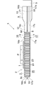
- Embodiment 1 This embodiment is shown in FIGS. 1 to 6, and the manufacturing method of the casing constituent member of the present invention is applied to the manufacturing of the casing constituent member of the liquid cooling type cooling device.
- FIGS. 1 to 4 show a liquid cooling type cooling apparatus provided with a casing made of components produced by the method of the present invention
- FIGS. 5 to 6 show a method for producing the components for the casing.
- FIG. 2 In the description of the liquid cooling type cooling apparatus based on FIGS. 1 to 4, the lower side of FIG. 2 is referred to as the front, the upper side is referred to as the rear, and the upper, lower, left and right in FIG.
- the liquid cooling type cooling device (1) is an inflow comprising a hollow casing (2) and a round pipe connected to the casing (2) and allowing the cooling liquid to flow into the casing (2).
- a pipe (3) and an outflow pipe (4) comprising a round pipe connected to the casing (2) and allowing the coolant to flow out of the casing (2) are provided.
- the casing (2) includes a top wall (6), a bottom wall (7), and a peripheral wall (8), and a rectangular parallelepiped casing body (5) in which a coolant flows, and a right edge of the casing body (5).
- the cooling liquid inflow part (9) (fluid passage part) that is integrally formed at the rear end of the casing and protrudes rightward and communicates with the casing body (5), and the front end of the right edge of the casing body (5).
- a cooling liquid outflow portion (11) (fluid passage portion) that is integrally formed in a rightward protruding shape and communicates with the inside of the casing body (5).
- the peripheral wall (8) of the casing body (5) has a vertical front side wall (8a) extending in the left-right direction, a vertical rear side wall (8b) extending in the left-right direction and facing the front side wall (8a), A vertical left side wall (8c) that extends in the front-rear direction and connects the left ends of the front side wall (8a) and the rear side wall (8b), and extends in the front-rear direction and faces the left side wall (8c). It consists of a vertical right wall (8d).
- the cooling liquid inflow portion (9) is provided continuously to the casing body (5) and has a rectangular tubular base portion (12) having the same height as the casing body (5), and a right end portion of the base portion (12).
- a cylindrical pipe connection portion (13) provided in a row and having the same outer diameter as the width in the front-rear direction of the outer surface of the base portion (12).
- the upper surface of the base portion (12) of the coolant inflow portion (9) is the upper surface of the top wall (6) of the casing body (5), the lower surface is the lower surface of the bottom wall (7), and the rear surface is the rear side wall of the peripheral wall (8). It is flush with the rear surface of the part (8b).
- the front surface of the base portion (12) is perpendicular to the right surface of the right wall portion (8d) of the peripheral wall (8).
- the coolant outflow portion (11) is connected to the casing body (5) and has a rectangular tubular base (14) having the same height as the casing body (5), and a right end portion of the base (14).
- a cylindrical pipe connection portion (15) provided in a row and having an outer diameter equal to the width in the front-rear direction of the outer surface of the base portion (14).
- the upper surface of the base (14) of the coolant outflow portion (11) is the upper surface of the top wall (6) of the casing body (5), the lower surface is the lower surface of the bottom wall (7), and the front surface is the front side wall of the peripheral wall (8). It is flush with the front surface of the part (8a).
- the rear surface of the base portion (12) is perpendicular to the right surface of the right side wall portion (8d) of the peripheral wall (8).
- the casing (2) consisting of the casing body (5), the coolant inflow part (9) and the coolant outflow part (11) is a top wall forming part (16a) that forms the top wall (6) of the casing body (5).
- the peripheral wall forming part (16b) forming the upper half of the peripheral wall (8) of the casing body (5), the cooling liquid inflow part (9) and the base (12) (14) of the cooling liquid outflow part (11)
- a base forming part (16c) that forms a half part, and a connection part forming part that forms the upper half part of the pipe connecting part (13) (15) of the coolant inflow part (9) and the coolant outflow part (11)
- the connecting part forming part (17d) (semi-cylindrical part) forming the lower half part of the connecting part (13) (15), and the upper constituent member (16) and the upper and lower symmetrical aluminum lower constituent parts ( 17) (casing component).
- the base forming portions (16c) and (17c) of the upper and lower constituent members (16) and (17) have a half-angled cylindrical shape that opens toward the other constituent member (17) and (16).
- the connecting portion forming portions (16d) and (17d) of the upper and lower constituent members (16) and (17) have a semi-cylindrical shape opened to the other constituent members (17) and (16).
- a horizontally flat outward projecting portion (18) is integrally formed from the lower end of the upper component member (16), that is, from the lower end of the peripheral wall forming portion (16b) to the lower end of the base portion forming portion (16c) and the connecting portion forming portion (16d). Is formed. Also, a horizontal flat outward projecting portion (19) extends from the upper end of the lower component member (17), that is, from the upper end of the peripheral wall forming portion (17b) to the upper end of the base portion forming portion (17c) and the connecting portion forming portion (17d). It is integrally formed.
- the casing (2) is formed by brazing the outwardly projecting portions (18) and (19) of the two component members (16) and (17).
- the portions present on the front and rear side edges of the connecting portion forming portion (16d) in the outward projecting portion (18) of the upper component member (16) are integrally formed on both side edges of the connecting portion forming portion (16d) and are coplanar. It is the horizontal flat part (21) located above. Further, the portions present on the front and rear side edges of the connecting portion forming portion (17d) in the outward projecting portion (19) of the lower component member (17) are integrally formed on both side edges of the connecting portion forming portion (17d) and It is a horizontal flat part (22) located on the same plane. And as shown in FIG.
- a wave crest portion Between the left wall portion (8c) and the right wall portion (8d) in the casing body (5) and between the coolant inflow portion (9) and the coolant outflow portion (11), a wave crest portion, An aluminum corrugated fin (23) comprising a wave bottom part and a vertical connecting part that connects the wave crest part and the wave bottom part is arranged, and the wave crest part is placed on the top wall (6) of the casing body (5). Are brazed to the bottom wall (7) of the casing body (5). And, by the corrugated fin (23), a plurality of flow paths (24) extending in the front-rear direction and flowing in the front-rear direction are formed side by side, thereby forming a plurality of flow paths (24).
- a parallel flow path portion (25) is provided.
- the upstream (rear) portion of the parallel flow passage portion (25) is an inlet header portion (26) leading to the coolant inflow portion (9), and the parallel flow passage portion ( A portion on the downstream side (front side) with respect to 25) serves as an outlet header portion (27) communicating with the coolant outflow portion (11).
- the semiconductor element (P) as a heating element is joined to the outer surface of the top wall (6) of the casing body (5) via the plate-like insulating member (I). Yes.
- the coolant sent from the coolant supply pipe (not shown) into the inflow pipe (3) flows into the inlet header section (26) in the casing body (5) through the coolant inflow section (9).
- the coolant flowing into the inlet header section (26) is divided into all the flow paths (24) of the parallel flow path section (25) in the inlet header section (26), and flows forward in all the flow paths (24). .
- the coolant that has flowed forward in the flow path (24) of the parallel flow path portion (25) enters the outlet header section (27) and flows to the right in the outlet header section (27). It flows into the outflow pipe (4) through (11).
- the coolant flowing into the outflow pipe (4) is sent into a coolant discharge pipe (not shown).
- the heat generated from the semiconductor element (P) is transferred to the coolant flowing in the flow path (24) through the insulating member (I), the top wall (6) of the casing body (5), and the corrugated fin (23).
- the semiconductor element (P) is cooled.
- the upper and lower constituent members (16) and (17) of the casing (2) will be described with reference to FIGS.
- the upper and lower sides and the left and right sides in FIG. the upper and lower constituent members (16) and (17) are vertically symmetric and have the same shape, and since both the constituent members (16) and (17) are manufactured by the same method, the upper constituent member (16) Only the manufacturing method will be described.
- a metal base plate made of an aluminum brazing sheet having a brazing filler metal layer on the upper surface is pressed using two molds (not shown) having a shape corresponding to the upper component member (16) of the final shape.
- a base forming part (16c) that forms the upper half of the base (12) (14) of the coolant inflow part (9) and the coolant outflow part (11), and the coolant inflow part (9) and the coolant outflow part (11) Pipe connection part (13)
- the semi-cylindrical connection part formation part (16d) that forms the upper half, and the base part formation part (16c) and the connection from the lower end of the peripheral wall formation part (16b) A first intermediate processed product (31) for the upper component member (16) having a horizontally flat outward projecting portion (18) formed integrally with the lower end of
- the inner peripheral surface of the peripheral wall forming portion (16b), the inner peripheral surface of the base portion forming portion (16c), the inner peripheral surface of the connecting portion forming portion (16d), and the outward projecting portion (18) (32 in the connecting portion forming portion (16d) is rounded at the connecting portion between the upper surface (the surface facing the opening side of the connecting portion forming portion (16d)) of the horizontal flat portion (21) Is formed (see FIG. 5A).
- the second inner workpiece (33) has an acute angle with respect to both side walls of the connecting portion forming portion (16d) on the inner side in the left-right direction (the connecting portion forming portion (16d) side) of both horizontal flat portions (21).
- forming the inclined flat portion (34) by bending the left and right outer portions of the horizontal flat portions (21) to form an obtuse angle, thereby forming the connection portion forming portion (16d) and the connection portion forming portion (16d).
- the third intermediate work product (36) composed of the horizontal narrow flat portion (35) which is narrower than () is produced (see FIG. 5 (c)).
- both inclined flat portions (34) are moved upward inward in the left-right direction (by pressing in the direction away from the bottom of the connecting portion forming portion (16d) toward the side wall side of the connecting portion forming portion (16d), the inclined portion flat portion (34) and the side wall of the connecting portion forming portion (16d)
- the material is collected at the joints of the above to produce a fourth intermediate processed product (37) (see FIG. 5 (d)).
- the inclination angle ⁇ with respect to the plane on which both horizontal flat portions (35) in the pressing direction with respect to both inclined flat portions (34) are located is preferably 5 to 20 degrees. .
- the upper part (opening side part), the inclined flat part (34) and the horizontal narrow flat part (35) of the side wall of the connection part forming part (16d) of the fourth intermediate processed product (37) are pressurized from above and below. Due to this, the connecting portion forming portion (16d) having the same depth as the upper constituent member (16) in the final shape, and the both sides of the connecting portion forming portion (16d) and the shape and the shape of the upper constituent member (16) in the final shape And a horizontal flat part (21) having the same dimensions, and a flash (38) protruding inward of the connection part forming part (16d) is formed at the upper end of both side walls of the connection part forming part (16d). The flash (38) is formed by the material flowing from the inclined flat part (34) and the horizontal narrow flat part (35).
- the connecting portion forming portion (16d) has a horizontal flat portion (21) integrally formed on both side edges and located on the same plane, and is flat with the inner peripheral surface of the connecting portion forming portion (16d).
- the upper component member (16) having the edge portion (20) formed at the connecting portion between the connecting portion forming portion (16d) of the portion (21) and the surface facing the opening side is formed (FIG. 5 (f)). reference).
- the manufacturing method of the upper and lower constituent members (16), (17) of the casing (2) of the liquid cooling type cooling device (1) has been described.
- the present invention is also applied to the manufacture of a pipe connecting component in which an edge portion is formed at a connecting portion between a flat portion and a surface facing the open side of the semi-cylindrical portion.
- Embodiment 2 This embodiment is shown in FIGS. 7 to 13, and the pipe connection structure to the hollow part of the present invention is applied to the connection of the inflow pipe and the outflow pipe to the pipe connection portion of the casing of the liquid cooling type cooling device. It is a thing.
- FIGS. 7 to 11 show a liquid cooling type cooling apparatus having a casing to which a pipe is connected by the pipe connection structure of the present invention
- FIGS. 12 and 13 show a method for connecting the pipe to the casing.
- FIG. 8 the lower side of FIG. 8 is the front and the upper side is the rear, and the upper and lower sides and the left and right sides of FIG.
- the upper and lower components (16) and (17) of the liquid cooling type cooling device (1) are pressed on an aluminum brazing sheet having a brazing filler metal layer on one side so that the brazing filler metal layer faces inward. It is formed by processing. Since the upper and lower constituent members (16), (17) are formed so that the brazing filler metal layer faces inward from the aluminum brazing sheet having the brazing filler metal layer on one side, the outwardly projecting portion of the upper constituent member (16) A brazing filler metal layer is present on the lower surface of (18) and the upper surface of the outwardly projecting portion (19) of the lower component member (17).
- the casing (2) is formed by brazing the outwardly projecting portions (18) and (19) of the two component members (16) and (17).
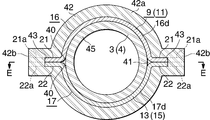
- the connecting portion forming portions (upper and lower constituent members (16) and (17)) 16d) The inner peripheral surface of 17d, the lower surface of the flat portion 21 of the upper component 16 (the surface facing the side where the connecting portion forming portion 16d of the flat portion 21 is opened) and the lower surface Roundness (40) is formed at the connecting part with the upper surface of the flat part (22) of the component (17) (the surface of the flat part (22) facing the side where the connecting part forming part (17d) is open). ing. Therefore, the inner peripheral surface of the pipe connection portion (13) (15) formed by the connection portion formation portion (16d) (17d) of the upper and lower constituent members (16) (17), the inflow pipe (3) and the outflow pipe There is a gap (41) between (4) and (4).
- connection structure of the inflow pipe (3) and the outflow pipe (4) to the pipe connection parts (13) and (15) of the casing (2) is as follows.
- the first outward flange (42) on the casing (2) side is provided at both ends of the upper and lower components (16, 17) at the tip of the pipe connecting portions (13, 15).
- the connecting portion forming portions (16d) and (17d) and the horizontal flat portions (21) and (22) are provided.
- the first outward flange (42) is formed separately from the upper and lower components (16), (17), that is, the pipe connection portions (13), (15), from an aluminum brazing sheet having a brazing filler metal layer on both sides.
- the annular portion (42a) and the outwardly projecting portion (42b) integrally formed so as to protrude radially outward and to be positioned one diameter above both the front and rear sides of the annular portion (42a) And more.
- the outer peripheral edge of the annular portion (42a) includes the inner peripheral surface of each connection portion forming portion (16d) (17d) of the upper and lower constituent members (16) (17) and the flat portion (21 of the upper constituent member (16)). ) And the roundness (40) of the connecting portion with the upper surface of the flat portion (22) of the lower component member (17).
- the first outward flange (42) extends from the inner peripheral edge of the annular portion (42a) to the intermediate portion in the inner and outer directions of both outward projecting portions (42b), and both horizontal flat portions (21) and (22).
- a notch (43) to be fitted is formed.
- the first outward flange (42) has the right ends of the horizontal flat portions (21) and (22) fitted in the notches (43), and the annular portion (42a) is connected to the pipe connecting portion (13). (15) is fitted around the end, and both outward projections (42b) are received by the receiving portions (21a) and (22a) of the horizontal flat portions (21) and (22).
- the brazing material layer is used to braze the pipe connecting portions (13) and (15) and the horizontal flat portions (21) and (22).
- the right side surface (outer side surface) of the first outward flange (42) is flush with the right end surfaces of the pipe connecting portions (13) (15) and the horizontal flat portions (21) (22).
- a joining auxiliary plate (44) formed of an aluminum brazing sheet having brazing material layers on both sides is brazed to the right side of the first outward flange (42).
- the joining auxiliary plate (44) is an outer portion formed integrally with the annular portion (44a) and the front and rear side portions of the annular portion (44a) so as to protrude radially outward and to be positioned one diameter above. It has the same shape and the same size as the first outward flange (42) except that it includes a protrusion (44b) and is not formed with a notch (43).
- the upper and lower side edges of the outward projection (44b) of the auxiliary joining plate (44) are the upper surface of the horizontal flat portion (21) of the upper component member (16) and the lower surface of the horizontal flat portion (22) of the lower component member (17).
- the outer edge in the front-rear direction is positioned on the same straight line as the outer edge in the front-rear direction of the horizontal flat portions (21), (22). Therefore, the joining auxiliary plate (44) is a flat formed on both the connecting portion forming portions (16d) and (17d) of the pipe connecting portions (13) and (15) of the refrigerant inflow portion (9) and the refrigerant outflow portion (11).
- each connecting part forming part Roundness (40) is formed at the connection between the inner peripheral surface of (16d) and (17d) and the surface facing the opening side of the connecting portion forming portion (16d) and (17d) in both flat portions (21) and (22)
- the inner peripheral surface of the pipe connection part (13) (15) formed by the connection part formation part (16d) (17d) of the upper and lower constituent members (16) (17) and the inflow pipe
- the opening end on the first outward flange (42) side (right side) of the gap (41) between (3) and the outflow pipe (4) is completely closed by the joining auxiliary plate (44). Therefore, fluid leakage from the casing (2) can be prevented.
- the inflow pipe (3) and the outflow pipe (4) are inserted into the pipe connection part (13) (15) of the casing (2) and the outside (right side) of the insertion part (45). ) And a second outward flange (46) formed integrally therewith, and the inserted portion (45) is brazed to the pipe connecting portion (13) (15) and the second outward flange ( 46) is brazed to the auxiliary joining plate (44).
- the outer peripheral edge of the brazed portion between the second outward flange (46) and the auxiliary joining plate (44) is the lower surface of the flat portion (21) of the upper component member (16) and the flat portion of the lower component member (17) ( 22) may be located either on the radially outer side or the inner side of the roundness (40) of the connecting portion with the upper surface.
- connection of the inflow pipe (3) and the outflow pipe (4) to the pipe connection part (13) (15) of the casing (2) is performed by the method described below simultaneously with the production of the liquid cooling type cooling device (1). Is called. That is, upper and lower constituent members (16) and (17), a first outward flange (42), a joining auxiliary plate (44), an inflow pipe (3) and an outflow pipe (4) are prepared. ) And (17) are combined so that the outwardly projecting portions (18) and (19) are in close contact with each other (see FIG. 12). At this time, the corrugated fin (23) is disposed between the upper and lower constituent members (16) (17).
- the annular portion (42a) of the first outward flange (42) is inserted into the notch (43) so that both horizontal flat portions (21) (22) fit into the notches (43).
- the outer projecting portion (42b) is brought into contact with the receiving portions (21a) and (22a) of both horizontal flat portions (21) and (22) (see FIG. 13 (a)).
- the joining auxiliary plate (44) is placed along the outer surface (right side surface) of the first outward flange (42) (see FIG.
- the refrigerant inflow pipe (3) and the refrigerant outflow pipe (4) The inserted portion (45) of the pipe is passed through the annular portion (44a) of the auxiliary joining plate (44) and the annular portion (42a) of the first outward flange (42) and the pipe connecting portion (13) (15).
- the second outward flange (46) is placed along the outer surface (right side surface) of the auxiliary joining plate (44) (see FIG. 13 (c)).
- the upper and lower components (16) and (17), the first outward flange (42) and the joining auxiliary plate (44) are temporarily fixed by appropriate means (not shown), and the refrigerant inflow pipe (3) and the refrigerant outflow pipe Temporarily fix (4) to the pipe connection (13) (15).
- the refrigerant inflow pipe (3) and the refrigerant outflow pipe (4) are temporarily fixed to the pipe connection portions (13) and (15).
- the shape of the clip is not limited to the illustrated shape, and can be changed as appropriate.
- the upper and lower components (16) and (17), the first outward flange (42), the joining auxiliary plate (44), the refrigerant inflow pipe (3) and the refrigerant outflow pipe (4) are heated to a predetermined brazing temperature.
- the outwardly projecting portions (18) and (19) of the upper and lower components (16) and (17) are brazed to form the casing (2), and at the same time, the pipe connecting portions (13) and (15) ) And the horizontal flat portion (21) (22) and the first outward flange (42), the first outward flange (42) and the auxiliary joining plate (44), the refrigerant inflow pipe (3) and the refrigerant outflow pipe (4)
- the inserted portion (45) and the pipe connecting portions (13) and (15), and the joining auxiliary plate (44) and the second outward flange (46) are brazed.
- the liquid cooling type cooling device (1) is manufactured.
- the semiconductor element (P) that is a heating element is cooled in the same manner as in the first embodiment.
- Embodiment 3 This embodiment is shown in FIGS. 14 to 16, and the pipe connection structure to the hollow part of the present invention is applied to the connection of the inflow pipe and the outflow pipe to the pipe connection portion of the casing of the liquid cooling type cooling device. It is a thing.
- annular projecting portion (42b) is not formed on the annular portion (50a) of the first outward flange (50), and the annular portion (50a) is radially outward from the inner peripheral edge thereof.
- a pair of cutouts (51) into which the two horizontal flat portions (21) and (22) fit are formed so as to be positioned on one diameter.
- the right ends of the horizontal flat portions (21) and (22) provided at the connecting portion forming portions (16d) and (17d) of the pipe connecting portions (13) and (15) of the casing (2) are outward from the right end in the front-rear direction. Cut out to the edge, the remaining part on the inner side in the front-rear direction than the cut off part at the right end of the horizontal flat part (21) (22) is fitted into the notch (51) of the first outward flange (50). ing.
- the portion on the left side of the cut portion in the horizontal flat portions (21) and (22) is the portion radially outside the notch (51) in the annular portion (50a) of the first outward flange (50).
- Receiving portions (21b) and (22b) for receiving are formed.
- the first outward flange (50) has an annular portion (50a) fitted around the ends of the pipe connecting portions (13) and (15), and both horizontal flat portions in the notches (51). (21) In the state where the portion protruding to the right of the receiving portion (21b) (22b) of (22) is fitted, the pipe connecting portion (13) (15) and The horizontal flat portions (21) and (22) are brazed. Here, the right side surface (outer side surface) of the first outward flange (50) was fitted into the notch (51) in the pipe connecting portion (13) (15) and the horizontal flat portion (21) (22). It is flush with the right edge of the part.
- auxiliary plate (44) between the first outward flange (50) and the second outward flange (46) of the inflow pipe (3) and the outflow pipe (4).
- Flange (50) (46) is brazed directly.
- the outer peripheral edge of the brazed part of both outward flanges (50), (46) is connected to the inner peripheral surface of each connection part forming part (16d), (17d) of the upper and lower constituent members (16), (17). It is positioned radially outward from the roundness (40) of the connecting portion between the lower surface of the flat portion (21) of the component member (16) and the upper surface of the flat portion (22) of the lower component member (17).
- the second outward flange (46) is formed in both the connecting portion forming portions (16d) and (17d) of the pipe connecting portions (13) and (15) of the refrigerant inflow portion (9) and the refrigerant outflow portion (11).
- the end portion (right end surface) of the portion fitted in the notch (51) of the first outward flange (50) in the flat portion (21) (22) is completely covered, and as a result, each connecting portion forming portion Roundness (40) is formed at the connection between the inner peripheral surface of (16d) and (17d) and the surface facing the opening side of the connecting portion forming portion (16d) and (17d) in both flat portions (21) and (22)
- the inner peripheral surface of the pipe connection part (13) (15) formed by the connection part formation part (16d) (17d) of the upper and lower constituent members (16) (17) and the inflow pipe
- the opening end on the first outward flange (50) side (right side) of the gap (41) between (3) and the outflow pipe (4) is completely closed by the second outward
- connection of the inflow pipe (3) and the outflow pipe (4) to the pipe connection part (13) (15) of the casing (2) is performed by the method described below simultaneously with the production of the liquid cooling type cooling device (1). Is called. That is, the upper and lower constituent members (16) and (17), the first outward flange (50), the inflow pipe (3) and the outflow pipe (4) are prepared. The side projecting portions (18) and (19) are combined so that they are in close contact with each other (see FIG. 16 (a)). At this time, the corrugated fin (23) is disposed between the upper and lower constituent members (16) (17).
- the pipe connection portion (13) is formed so that the annular portion (50a) of the first outward flange (50) is fitted into the notches (51) so that the remaining portions at the right ends of both horizontal flat portions (21) and (22) are fitted. ) (15) and the annular portion (50a) is brought into contact with the receiving portions (21b) and (22b) of both horizontal flat portions (21) and (22) (see FIG. 16 (b)).
- the inserted portion (45) of the refrigerant inflow pipe (3) and the refrigerant outflow pipe (4) is passed through the annular portion (50a) of the first outward flange (50) and the pipe connection portion (13) (15 ) And the second outward flange (46) along the outer surface (right side surface) of the first outward flange (50) (see FIG. 16 (c)).
- the upper and lower components (16) and (17), the first outward flange (50), the refrigerant inflow pipe (3) and the refrigerant outflow pipe (4) are temporarily fixed by appropriate means (not shown), and predetermined brazing is performed.
- the outwardly projecting portions (18) and (19) of the upper and lower constituent members (16) and (17) are brazed to form the casing (2), and at the same time, the pipe connection portion (13 ) (15) and the horizontal flat portion (21) (22) and the first outward flange (50), the first outward flange (50) and the second outward flange (46), and the refrigerant inflow pipe (3) and The inserted part (45) and the pipe connecting parts (13), (15) of the refrigerant outflow pipe (4) are brazed.
- the liquid cooling type cooling device (1) is manufactured.
- Embodiment 4 This embodiment is shown in FIGS. 17 to 19, and the pipe connection structure to the hollow part of the present invention is applied to the connection of the inflow pipe and the outflow pipe to the pipe connection portion of the casing of the liquid cooling type cooling device. It is a thing.
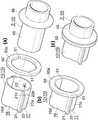
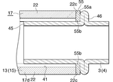
- the outer peripheral edge of the annular portion (55a) of the first outward flange (55) is the inner peripheral surface of each connection portion forming portion (16d) (17d) of the upper and lower constituent members (16) (17) and the upper structure It is positioned radially outward from the roundness (40) of the connecting portion between the lower surface of the flat portion (21) of the member (16) and the upper surface of the flat portion (22) of the lower component member (17).
- an inward protruding portion (55b) that protrudes radially inward and is positioned one diameter above is integrally formed.
- the inner edge of the inward projecting portion (55b) has an arc shape, and the curvature thereof is the curvature of the inner peripheral surface of the pipe connecting portion (13) (15) and the outer peripheral surface of the inflow pipe (3) and the outflow pipe (4). It is equal to.
- An inward projecting portion (55b) of the first outward flange (55) is formed on the right end of the pipe connecting portion (13) (15) of the casing (2) so as to straddle both connecting portion forming portions (16d) (17d). ) Is formed so as to be positioned one diameter above.
- the right end of the horizontal flat part (21) (22) provided in each connection part formation part (16d) (17d) of the pipe connection part (13) (15) is the depth of the notch (56) (left-right direction)
- the right end of the remaining part of the horizontal flat part (21) (22) is cut out so that the part with the same length as the dimension of (1)) does not interfere with the annular part (55a) of the first outward flange (55)
- receiving portions (21c) and (22c) for receiving the annular portion (55a) of the first outward flange (55) are formed.
- the first outward flange (55) has an annular portion (55a) fitted around the ends of the pipe connecting portions (13) and (15), and an inward protruding portion in the notch (56).
- connection of the inflow pipe (3) and the outflow pipe (4) to the pipe connection part (13) (15) of the casing (2) is performed by the method described below simultaneously with the production of the liquid cooling type cooling device (1). Is called. That is, the upper and lower components (16) and (17), the first outward flange (55), the inflow pipe (3) and the outflow pipe (4) are prepared, and the upper and lower components (16) and (17) are The side projecting portions (18) and (19) are combined so that they are in close contact with each other (see FIG. 19 (a)). At this time, the corrugated fin (23) is disposed between the upper and lower constituent members (16) (17).
- annular part (55a) of the first outward flange (55) is fitted around the pipe connecting part (13) (15) so that the inward protruding part (55b) fits into the notch (56). Then, the annular portion (55a) is brought into contact with the receiving portions (21c) and (22c) of both horizontal flat portions (21) and (22) (see FIG. 19 (b)).
- the inserted portion (45) of the refrigerant inflow pipe (3) and the refrigerant outflow pipe (4) is passed through the annular portion (55a) of the first outward flange (55) and the pipe connection portion (13) (15 ) And the second outward flange (46) along the outer surface (right side surface) of the first outward flange (55) (see FIG. 19 (c)).
- the upper and lower components (16) and (17), the first outward flange (55), the refrigerant inflow pipe (3) and the refrigerant outflow pipe (4) are temporarily fixed by appropriate means (not shown), and predetermined brazing is performed.
- the outwardly projecting portions (18) and (19) of the upper and lower constituent members (16) and (17) are brazed to form the casing (2), and at the same time, the pipe connection portion (13 ) (15) and the horizontal flat portion (21) (22) and the first outward flange (55), the first outward flange (55) and the second outward flange (46), and the refrigerant inflow pipe (3) and The inserted part (45) and the pipe connecting parts (13), (15) of the refrigerant outflow pipe (4) are brazed.
- the liquid cooling type cooling device (1) is manufactured.
- the coolant inflow part (9) of the casing (2) and the pipe connection part of the refrigerant outflow part (11) (13) (15) is cylindrical, and the connecting portion forming portions (16d) (17d) of the upper and lower constituent members (16) (17) are semi-cylindrical, but it is not limited thereto.
- the cross-sectional shapes of the inflow pipe (3) and the outflow pipe (4) can be appropriately changed to oval, oval, polygon, etc., and the coolant inflow section (9) and the refrigerant outflow section of the casing (2)
- the shape of the pipe connection part (13) (15) of (11) and the shape of the connection part forming part (16d) (17d) of both the upper and lower components (16) (17) are also the inflow pipe (3) and the outflow It is appropriately changed according to the cross-sectional shape of the pipe (4).
- the method for manufacturing a pipe connection part of the present invention is applied to manufacture of a pipe connection part used in a liquid cooling type cooling device that cools a heating element made of an electronic part such as a semiconductor element.
- the pipe connection structure to the hollow part of the present invention is applied to the connection of the pipe to the hollow part used in the liquid cooling type cooling device for cooling the heating element made of an electronic part such as a semiconductor element.
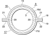
- FIG. 3 is a sectional view taken along line AA in FIG. 2.
- FIG. 3 is an enlarged sectional view taken along line BB in FIG. 2.
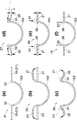
- It is an expanded sectional view of the part of the connection part formation part which shows the manufacturing method of the upper structural member in the casing of the liquid cooling type cooling device of FIG. 1 in order of a process. It is a figure which expands and shows the principal part of FIG.5 (e).
- FIG. 9 is an enlarged sectional view taken along line DD of FIG. 8.
- FIG. 9 is a perspective view which shows 1 process of the connection method of the inflow pipe and the outflow pipe to the pipe connection part of the casing of the liquid cooling type cooling device of FIG. It is a perspective view which shows the process following FIG.
- FIG. 10 shows the principal part of the liquid cooling type cooling device which applied the pipe connection structure of Embodiment 3 of this invention to the connection of the inflow pipe and the outflow pipe to the pipe connection part of a casing.
- FIG. 10 shows the principal part of the liquid cooling type cooling device which applied the pipe connection structure of Embodiment 3 of this invention to the connection of the inflow pipe and the outflow pipe to the pipe connection part of a casing.
- FIG. 10 shows the principal part of the liquid cooling type cooling device which applied the pipe connection structure of Embodiment 3 of this invention to the connection of the inflow pipe and the outflow pipe to the pipe connection part of a casing.
- FIG. 10 shows the principal part of the liquid cooling type cooling device which applied the pipe connection structure of Embodiment 3 of this invention to the connection of the inflow pipe and the outflow pipe to the pipe connection part of a casing.
- FIG. 10 shows the principal part of the liquid cooling type cooling device which applied the pipe connection structure of Embodiment 3 of this invention to the connection of the
- FIG. 10 which shows the principal part of the liquid cooling type cooling device which applied the pipe connection structure of Embodiment 4 of this invention to the connection of the inflow pipe to the pipe connection part of a casing, and an outflow pipe.
- FIG. 18 is a cross-sectional view taken along the line GG of FIG. It is a perspective view which shows the connection method of the inflow pipe and the outflow pipe to the pipe connection part of the casing of the liquid cooling type cooling device of FIG. It is sectional drawing equivalent to FIG. 4 which shows the problem of the liquid cooling type cooling device provided with the casing which consists of a structural member manufactured by the conventional method.
Landscapes
- Engineering & Computer Science (AREA)
- Mechanical Engineering (AREA)
- General Engineering & Computer Science (AREA)
- Physics & Mathematics (AREA)
- Thermal Sciences (AREA)
- Shaping Metal By Deep-Drawing, Or The Like (AREA)
- Body Structure For Vehicles (AREA)
- Cooling Or The Like Of Semiconductors Or Solid State Devices (AREA)
Abstract
Cette invention se rapporte à un procédé de fabrication d'un élément structural d'enveloppe capable d'empêcher une fuite de fluide, le procédé comprenant les étapes suivantes : une première étape pour former un premier article préformé 42 qui comprend une partie formation de partie raccordement 16d et une partie plate 21 ; une deuxième étape pour former un deuxième article préformé 44 ayant une partie formation de partie raccordement 16d qui présente une plus grande profondeur de pliage et une partie plate 21 qui présente une largeur plus étroite que le premier article préformé 42 ; une troisième étape pour former un troisième article préformé 36 ayant une partie formation de partie raccordement 16d, une partie plate inclinée 34, et une partie plate de largeur étroite 35 ; une quatrième étape pour former un quatrième article préformé 37, la partie plate inclinée 34 du troisième article préformé 36 étant poussée vers le haut et le matériau étant recueilli à l'intérieur d'une partie raccordement entre la partie plate inclinée 35 et une paroi latérale de la partie formation de partie raccordement 16d ; une cinquième étape pour former un cinquième article préformé 39, une pression étant appliquée à la paroi latérale de la partie formation de partie raccordement 16d du quatrième article préformé 37, à la partie plate inclinée 34 et à la partie plate de largeur étroite 35 par dessus et par en dessous, et une bavure 38 étant formée dans une partie d'extrémité ouverte entre les deux parois latérales de la partie formation de partie raccordement 16d ; et une sixième étape pour éliminer la bavure 38 de manière à former un élément structural d'enveloppe 16.
Priority Applications (3)
| Application Number | Priority Date | Filing Date | Title |
|---|---|---|---|
| EP09712336.8A EP2260957B1 (fr) | 2008-02-19 | 2009-02-17 | Procédé de fabrication d'un composant de raccordement de tuyaux |
| US12/735,466 US8418517B2 (en) | 2008-02-19 | 2009-02-17 | Method of manufacturing a pipe coupling component |
| CN2009801056529A CN101952064B (zh) | 2008-02-19 | 2009-02-17 | 管连接部件的制造方法以及壳体构成部件的制造方法 |
Applications Claiming Priority (4)
| Application Number | Priority Date | Filing Date | Title |
|---|---|---|---|
| JP2008-036864 | 2008-02-19 | ||
| JP2008036864A JP5033673B2 (ja) | 2008-02-19 | 2008-02-19 | パイプ接続部品の製造方法およびケーシング構成部材の製造方法 |
| JP2008089866A JP2009243563A (ja) | 2008-03-31 | 2008-03-31 | 中空部品へのパイプ接続構造 |
| JP2008-089866 | 2008-03-31 |
Publications (1)
| Publication Number | Publication Date |
|---|---|
| WO2009104575A1 true WO2009104575A1 (fr) | 2009-08-27 |
Family
ID=40985455
Family Applications (1)
| Application Number | Title | Priority Date | Filing Date |
|---|---|---|---|
| PCT/JP2009/052635 Ceased WO2009104575A1 (fr) | 2008-02-19 | 2009-02-17 | Procédé de fabrication d'un composant de raccordement de tuyaux, procédé de fabrication d'un élément structural d'enveloppe, et structure de raccordement de tuyaux pour une partie creuse |
Country Status (4)
| Country | Link |
|---|---|
| US (1) | US8418517B2 (fr) |
| EP (1) | EP2260957B1 (fr) |
| CN (1) | CN101952064B (fr) |
| WO (1) | WO2009104575A1 (fr) |
Cited By (1)
| Publication number | Priority date | Publication date | Assignee | Title |
|---|---|---|---|---|
| JP2024121781A (ja) * | 2023-02-27 | 2024-09-06 | ベンテラー・アウトモビールテヒニク・ゲゼルシャフト・ミト・ベシュレンクテル・ハフツング | 伝熱プレート及び伝熱プレートを製造するための方法 |
Families Citing this family (17)
| Publication number | Priority date | Publication date | Assignee | Title |
|---|---|---|---|---|
| JP6156142B2 (ja) * | 2011-04-13 | 2017-07-05 | 日本電気株式会社 | 冷却装置の配管構造、その製造方法、及び配管接続方法 |
| DE102011052707A1 (de) * | 2011-08-15 | 2013-02-21 | Pierburg Gmbh | Kühlvorrichtung für ein thermisch belastetes Bauteil |
| JP5926928B2 (ja) * | 2011-11-04 | 2016-05-25 | 昭和電工株式会社 | パワー半導体モジュール冷却装置 |
| EP2793261B1 (fr) | 2013-04-18 | 2016-04-13 | ABB Technology Oy | Appareil |
| JP1526104S (fr) * | 2013-12-06 | 2015-06-15 | ||
| CN105637632B (zh) * | 2014-03-20 | 2019-07-23 | 富士电机株式会社 | 冷却器及使用该冷却器的半导体模块 |
| CN105814685B (zh) | 2014-05-20 | 2018-07-13 | 富士电机株式会社 | 半导体模块用冷却器及其制造方法 |
| US10006571B2 (en) * | 2014-08-27 | 2018-06-26 | International Business Machines Corporation | Releasable, threadless conduit connector for liquid manifold |
| JP6513427B2 (ja) * | 2015-02-27 | 2019-05-15 | 昭和電工株式会社 | 液冷式冷却装置 |
| JP6663899B2 (ja) * | 2017-11-29 | 2020-03-13 | 本田技研工業株式会社 | 冷却装置 |
| DE102017129749A1 (de) * | 2017-12-13 | 2019-06-13 | Webasto SE | Plattenwärmetauscher |
| JP7494453B2 (ja) * | 2019-09-04 | 2024-06-04 | 株式会社レゾナック | 熱交換器 |
| CN212084987U (zh) * | 2020-07-09 | 2020-12-04 | 宁波市哈雷换热设备有限公司 | 一种承压能力强的芯片冷却器 |
| EP4113050A1 (fr) * | 2021-06-30 | 2023-01-04 | Valeo Vymeniky Tepla S.r.o. | Échangeur de chaleur |
| US12241698B2 (en) * | 2021-08-10 | 2025-03-04 | Delta Electronics, Inc. | Connecting device of liquid cooling module |
| DE102021124268A1 (de) | 2021-09-20 | 2023-03-23 | Akg Verwaltungsgesellschaft Mbh | Wärmeaustauscher |
| HUE071718T2 (hu) * | 2023-02-27 | 2025-09-28 | Benteler Automobiltechnik Gmbh | Hõcserélõ lemez |
Citations (7)
| Publication number | Priority date | Publication date | Assignee | Title |
|---|---|---|---|---|
| JPS6234690U (fr) * | 1985-08-19 | 1987-02-28 | ||
| JPS63154985U (fr) * | 1987-03-26 | 1988-10-12 | ||
| JPH02274373A (ja) * | 1989-04-13 | 1990-11-08 | Zexel Corp | 積層型熱交換器 |
| JPH07280484A (ja) * | 1994-04-06 | 1995-10-27 | Calsonic Corp | 積層型熱交換器 |
| JP2000055255A (ja) * | 1998-08-11 | 2000-02-22 | Usui Internatl Ind Co Ltd | 細径配管接続構造 |
| JP2005274120A (ja) | 2004-02-24 | 2005-10-06 | Showa Denko Kk | 液冷式冷却板 |
| JP2008224134A (ja) * | 2007-03-13 | 2008-09-25 | T Rad Co Ltd | 熱交換器のパイプ取付け部の製造方法およびそのパイプ取付け部構造 |
Family Cites Families (5)
| Publication number | Priority date | Publication date | Assignee | Title |
|---|---|---|---|---|
| US3457761A (en) * | 1967-03-20 | 1969-07-29 | Western Electric Co | Method and apparatus for drawing and stretching a flat blank into a tubular shell |
| JPS6033831A (ja) * | 1983-07-31 | 1985-02-21 | Matsushita Electric Works Ltd | 絞り加工法 |
| JPS6234690A (ja) | 1985-08-06 | 1987-02-14 | Toyota Motor Corp | 自動車用エンジンバルブおよびその製造方法 |
| JPH07119808B2 (ja) | 1986-12-18 | 1995-12-20 | セイコー電子工業株式会社 | 腕時計用文字板 |
| CN1960585A (zh) * | 2006-09-29 | 2007-05-09 | 北京桑普电器有限公司 | 一种翅片式电热管及加工工艺和设备 |
-
2009
- 2009-02-17 US US12/735,466 patent/US8418517B2/en not_active Expired - Fee Related
- 2009-02-17 CN CN2009801056529A patent/CN101952064B/zh not_active Expired - Fee Related
- 2009-02-17 WO PCT/JP2009/052635 patent/WO2009104575A1/fr not_active Ceased
- 2009-02-17 EP EP09712336.8A patent/EP2260957B1/fr not_active Not-in-force
Patent Citations (7)
| Publication number | Priority date | Publication date | Assignee | Title |
|---|---|---|---|---|
| JPS6234690U (fr) * | 1985-08-19 | 1987-02-28 | ||
| JPS63154985U (fr) * | 1987-03-26 | 1988-10-12 | ||
| JPH02274373A (ja) * | 1989-04-13 | 1990-11-08 | Zexel Corp | 積層型熱交換器 |
| JPH07280484A (ja) * | 1994-04-06 | 1995-10-27 | Calsonic Corp | 積層型熱交換器 |
| JP2000055255A (ja) * | 1998-08-11 | 2000-02-22 | Usui Internatl Ind Co Ltd | 細径配管接続構造 |
| JP2005274120A (ja) | 2004-02-24 | 2005-10-06 | Showa Denko Kk | 液冷式冷却板 |
| JP2008224134A (ja) * | 2007-03-13 | 2008-09-25 | T Rad Co Ltd | 熱交換器のパイプ取付け部の製造方法およびそのパイプ取付け部構造 |
Non-Patent Citations (1)
| Title |
|---|
| See also references of EP2260957A4 |
Cited By (3)
| Publication number | Priority date | Publication date | Assignee | Title |
|---|---|---|---|---|
| JP2024121781A (ja) * | 2023-02-27 | 2024-09-06 | ベンテラー・アウトモビールテヒニク・ゲゼルシャフト・ミト・ベシュレンクテル・ハフツング | 伝熱プレート及び伝熱プレートを製造するための方法 |
| JP7705441B2 (ja) | 2023-02-27 | 2025-07-09 | ベンテラー・アウトモビールテヒニク・ゲゼルシャフト・ミト・ベシュレンクテル・ハフツング | 伝熱プレート及び伝熱プレートを製造するための方法 |
| US12510309B2 (en) | 2023-02-27 | 2025-12-30 | Benteler Automobiltechnik Gmbh | Heat exchanger plate and method for producing a heat exchanger plate |
Also Published As
| Publication number | Publication date |
|---|---|
| EP2260957B1 (fr) | 2015-07-08 |
| EP2260957A4 (fr) | 2014-02-26 |
| EP2260957A1 (fr) | 2010-12-15 |
| US8418517B2 (en) | 2013-04-16 |
| CN101952064A (zh) | 2011-01-19 |
| CN101952064B (zh) | 2013-11-13 |
| US20100320753A1 (en) | 2010-12-23 |
Similar Documents
| Publication | Publication Date | Title |
|---|---|---|
| WO2009104575A1 (fr) | Procédé de fabrication d'un composant de raccordement de tuyaux, procédé de fabrication d'un élément structural d'enveloppe, et structure de raccordement de tuyaux pour une partie creuse | |
| CN101405560B (zh) | 扁平管道、扁平管道热交换器及其制造方法 | |
| JPH05172488A (ja) | 熱交換器用ヘッダ−パイプの仕切板組付構造及び組付方法 | |
| CN101405557A (zh) | 扁平管道、扁平管道热交换器及其制造方法 | |
| CN103925826A (zh) | 热交换器用管 | |
| US8925625B2 (en) | Heat exchanger | |
| KR20150053135A (ko) | 열교환기 및 그 제조방법 | |
| US8726507B2 (en) | Method for manufacturing a heat exchanger and exchanger obtained by the method | |
| JP5033673B2 (ja) | パイプ接続部品の製造方法およびケーシング構成部材の製造方法 | |
| JP2009243563A (ja) | 中空部品へのパイプ接続構造 | |
| US10888910B2 (en) | Machining method for burred flat holes in metal plates | |
| JP2009257719A (ja) | 熱交換器 | |
| JP6530235B2 (ja) | 熱交換器及びその製造方法 | |
| JP2009008347A (ja) | 熱交換器 | |
| JP2005207726A (ja) | 熱交換器およびその製造方法 | |
| JP5264304B2 (ja) | ろう付パイプの製造方法および熱交換器の製造方法 | |
| JP5639844B2 (ja) | 液流通装置およびその製造方法 | |
| JP6276114B2 (ja) | ヘッダプレートレス熱交換器用偏平チューブ | |
| JP6083272B2 (ja) | 熱交換器 | |
| KR20130024019A (ko) | 응축기용 냉매파이프 고정구조 및 그 고정방법 | |
| JP2005076926A (ja) | 熱交換器及びその製造方法 | |
| JP4371417B2 (ja) | 熱交換器の製造方法 | |
| JPH09303988A (ja) | ヘッダタンクの製造方法 | |
| JP5624823B2 (ja) | 液冷式冷却装置 | |
| JP2014001902A (ja) | 熱交換器用チューブ |
Legal Events
| Date | Code | Title | Description |
|---|---|---|---|
| WWE | Wipo information: entry into national phase |
Ref document number: 200980105652.9 Country of ref document: CN |
|
| 121 | Ep: the epo has been informed by wipo that ep was designated in this application |
Ref document number: 09712336 Country of ref document: EP Kind code of ref document: A1 |
|
| WWE | Wipo information: entry into national phase |
Ref document number: 12735466 Country of ref document: US |
|
| NENP | Non-entry into the national phase |
Ref country code: DE |
|
| WWE | Wipo information: entry into national phase |
Ref document number: 2009712336 Country of ref document: EP |