WO2009104582A1 - Dispositif de réception, dispositif d'émission, système de communication et procédé de communication - Google Patents
Dispositif de réception, dispositif d'émission, système de communication et procédé de communication Download PDFInfo
- Publication number
- WO2009104582A1 WO2009104582A1 PCT/JP2009/052650 JP2009052650W WO2009104582A1 WO 2009104582 A1 WO2009104582 A1 WO 2009104582A1 JP 2009052650 W JP2009052650 W JP 2009052650W WO 2009104582 A1 WO2009104582 A1 WO 2009104582A1
- Authority
- WO
- WIPO (PCT)
- Prior art keywords
- signal
- data
- unit
- transmission
- retransmission
- Prior art date
- Legal status (The legal status is an assumption and is not a legal conclusion. Google has not performed a legal analysis and makes no representation as to the accuracy of the status listed.)
- Ceased
Links
Images


Classifications
-
- H—ELECTRICITY
- H04—ELECTRIC COMMUNICATION TECHNIQUE
- H04L—TRANSMISSION OF DIGITAL INFORMATION, e.g. TELEGRAPHIC COMMUNICATION
- H04L1/00—Arrangements for detecting or preventing errors in the information received
- H04L1/12—Arrangements for detecting or preventing errors in the information received by using return channel
- H04L1/16—Arrangements for detecting or preventing errors in the information received by using return channel in which the return channel carries supervisory signals, e.g. repetition request signals
- H04L1/18—Automatic repetition systems, e.g. Van Duuren systems
- H04L1/1812—Hybrid protocols; Hybrid automatic repeat request [HARQ]
-
- H—ELECTRICITY
- H04—ELECTRIC COMMUNICATION TECHNIQUE
- H04J—MULTIPLEX COMMUNICATION
- H04J11/00—Orthogonal multiplex systems, e.g. using WALSH codes
- H04J11/0023—Interference mitigation or co-ordination
- H04J11/0026—Interference mitigation or co-ordination of multi-user interference
- H04J11/0036—Interference mitigation or co-ordination of multi-user interference at the receiver
- H04J11/004—Interference mitigation or co-ordination of multi-user interference at the receiver using regenerative subtractive interference cancellation
-
- H—ELECTRICITY
- H04—ELECTRIC COMMUNICATION TECHNIQUE
- H04L—TRANSMISSION OF DIGITAL INFORMATION, e.g. TELEGRAPHIC COMMUNICATION
- H04L1/00—Arrangements for detecting or preventing errors in the information received
- H04L1/004—Arrangements for detecting or preventing errors in the information received by using forward error control
- H04L1/0045—Arrangements at the receiver end
- H04L1/0047—Decoding adapted to other signal detection operation
- H04L1/005—Iterative decoding, including iteration between signal detection and decoding operation
-
- H—ELECTRICITY
- H04—ELECTRIC COMMUNICATION TECHNIQUE
- H04L—TRANSMISSION OF DIGITAL INFORMATION, e.g. TELEGRAPHIC COMMUNICATION
- H04L1/00—Arrangements for detecting or preventing errors in the information received
- H04L1/12—Arrangements for detecting or preventing errors in the information received by using return channel
- H04L1/16—Arrangements for detecting or preventing errors in the information received by using return channel in which the return channel carries supervisory signals, e.g. repetition request signals
- H04L1/18—Automatic repetition systems, e.g. Van Duuren systems
- H04L1/1812—Hybrid protocols; Hybrid automatic repeat request [HARQ]
- H04L1/1819—Hybrid protocols; Hybrid automatic repeat request [HARQ] with retransmission of additional or different redundancy
-
- H—ELECTRICITY
- H04—ELECTRIC COMMUNICATION TECHNIQUE
- H04L—TRANSMISSION OF DIGITAL INFORMATION, e.g. TELEGRAPHIC COMMUNICATION
- H04L1/00—Arrangements for detecting or preventing errors in the information received
- H04L1/12—Arrangements for detecting or preventing errors in the information received by using return channel
- H04L1/16—Arrangements for detecting or preventing errors in the information received by using return channel in which the return channel carries supervisory signals, e.g. repetition request signals
- H04L1/18—Automatic repetition systems, e.g. Van Duuren systems
- H04L1/1829—Arrangements specially adapted for the receiver end
- H04L1/1835—Buffer management
- H04L1/1845—Combining techniques, e.g. code combining
-
- H—ELECTRICITY
- H04—ELECTRIC COMMUNICATION TECHNIQUE
- H04L—TRANSMISSION OF DIGITAL INFORMATION, e.g. TELEGRAPHIC COMMUNICATION
- H04L1/00—Arrangements for detecting or preventing errors in the information received
- H04L1/12—Arrangements for detecting or preventing errors in the information received by using return channel
- H04L1/16—Arrangements for detecting or preventing errors in the information received by using return channel in which the return channel carries supervisory signals, e.g. repetition request signals
- H04L1/18—Automatic repetition systems, e.g. Van Duuren systems
- H04L1/1829—Arrangements specially adapted for the receiver end
- H04L1/1854—Scheduling and prioritising arrangements
-
- H—ELECTRICITY
- H04—ELECTRIC COMMUNICATION TECHNIQUE
- H04L—TRANSMISSION OF DIGITAL INFORMATION, e.g. TELEGRAPHIC COMMUNICATION
- H04L1/00—Arrangements for detecting or preventing errors in the information received
- H04L1/12—Arrangements for detecting or preventing errors in the information received by using return channel
- H04L1/16—Arrangements for detecting or preventing errors in the information received by using return channel in which the return channel carries supervisory signals, e.g. repetition request signals
- H04L1/18—Automatic repetition systems, e.g. Van Duuren systems
- H04L1/1867—Arrangements specially adapted for the transmitter end
- H04L1/1893—Physical mapping arrangements
-
- H—ELECTRICITY
- H04—ELECTRIC COMMUNICATION TECHNIQUE
- H04B—TRANSMISSION
- H04B1/00—Details of transmission systems, not covered by a single one of groups H04B3/00 - H04B13/00; Details of transmission systems not characterised by the medium used for transmission
- H04B1/69—Spread spectrum techniques
- H04B1/707—Spread spectrum techniques using direct sequence modulation
- H04B1/7097—Interference-related aspects
- H04B1/7103—Interference-related aspects the interference being multiple access interference
- H04B1/7107—Subtractive interference cancellation
Definitions
- the present invention relates to a receiving device, a transmitting device, a communication system, and a communication method.
- OFDM Orthogonal Frequency Division Multiplexing
- OFDMA Orthogonal Frequency Division Multiple Access
- Intersymbol interference ISI: Inter Symbol Interference
- ICI Inter Carrier Interference
- Patent Document 1 proposes a method for improving characteristic degradation due to intersymbol interference (ISI) and intercarrier interference (ICI) when there is an incoming wave exceeding the guard interval (GI).
- ISI intersymbol interference
- ICI intercarrier interference
- a signal including an intersymbol interference (ISI) component and an intercarrier interference (ICI) component is obtained using an error correction result (an output of the MAP decoder).
- a duplicate signal (replica signal) of subcarriers other than the desired one is created.
- the receiving apparatus performs a demodulation operation again on the signal obtained by removing the created duplicate signal from the received signal. This prevents characteristic deterioration due to intersymbol interference (ISI) and intercarrier interference (ICI).
- ISI intersymbol interference
- ICI intercarrier interference
- MC-CDM Multi Carrier-Code Multiplexing
- MC-CDMA Multi-Carrier-Code
- CDM Code Division Multiplexing
- Division Multiple Access Multi-carrier code division multiple access
- Spread-OFCDM Orthogonal Frequency and Code Division Multiplexing
- Patent Document 2 and Non-Patent Document 1 describe a method for improving characteristic deterioration due to the loss of orthogonality between the codes.
- these conventional techniques have a difference between downlink and uplink, both relate to techniques for removing inter-code interference due to code multiplexing during MC-CDM communication.
- characteristics are improved by removing signals other than the desired code using data after error correction or after despreading.
- the signal is generated after demodulating the received signal in the receiving device in order to cancel interference such as inter-symbol interference (ISI), inter-carrier interference (ICI), and inter-code interference (MCI).
- ISI inter-symbol interference
- ICI inter-carrier interference
- MCI inter-code interference
- An interference signal is generated based on a replica signal to be performed, and interference cancellation is performed. Further, by repeating these processes, the accuracy of the replica signal is improved and interference is canceled with high accuracy.
- ISI inter-symbol interference
- ICI inter-carrier interference
- MCI inter-code interference
- Non-Patent Document 2 Non-Patent Document 3
- HARQ hybrid automatic retransmission
- CC chase combining
- IR incremental redundancy
- the hybrid automatic retransmission has a problem that the overhead on the link capacity due to the retransmission packet increases as the number of retransmission packets increases.
- the number of retransmissions of a signal transmitted from the transmission device to the reception device increases, and the end-to-end delay time increases.
- the present invention has been made in view of the above circumstances, and an object thereof is to provide a receiving device, a transmitting device, a communication system, and a communication method capable of reducing the number of retransmissions of a signal transmitted from the transmitting device to the receiving device. There is to do.
- a receiving device is a receiving device that communicates with a transmitting device, and a signal obtained by multiplexing a plurality of data signals.
- a reception unit that receives from the transmission device; and a data signal detection unit that determines success or failure of detection of transmission data for each of the data signals from the reception signal received by the reception unit, wherein the reception unit is the multiplexed
- a retransmission data signal corresponding to at least one of data signals that failed to detect transmission data among a plurality of data signals is further received from the transmission device, and the data signal detection unit includes the reception signal, the retransmission data signal, To a data signal corresponding to the retransmission data signal and at least one data signal not corresponding to the retransmission data signal among the plurality of multiplexed data signals. Determining the success or failure of re-detection of transmission data that.
- the data signal detection unit of the receiving device includes a data signal replica generation unit that generates a data signal replica that is a replica of each data signal, and an interference signal replica from the data signal replica.
- An interference signal replica generation unit to generate, an interference removal unit that subtracts the interference signal replica from the received signal, a signal synthesis unit that synthesizes the reception signal from which the interference signal replica has been removed, and a signal synthesized by the signal synthesis unit
- a determination unit that detects transmission data included in the plurality of multiplexed data signals.
- the signal synthesis unit of the reception device includes a reception signal from which the interference signal replica is removed, a demodulation unit that demodulates the retransmission signal, and a reception signal from which the interference signal replica is removed.
- a combining unit configured to combine the demodulation result and the demodulation result of the retransmission signal;
- the demodulation unit of the reception device outputs the reception signal from which the interference signal replica is removed and the likelihood information of the transmission data included in the retransmission signal.
- the demodulation unit of the reception device outputs a log likelihood ratio between the reception signal from which the interference signal replica is removed and the transmission data included in the retransmission signal, and the combination unit Then, the log likelihood ratio of the transmission data included in the reception signal from which the interference signal replica is removed and the log likelihood ratio of the transmission data included in the retransmission signal are added and combined.
- the interference signal replica generation unit of the reception device generates an interference signal replica for each of the data signals to be detected.
- the interference signal replica generation unit of the reception device generates an interference signal replica for a data signal other than the data signal to be detected first among the plurality of data signals to be detected.
- the reception device is configured to determine success / failure information regarding a data signal in which the redetection of the transmission data is successful based on the success / failure of the transmission data redetection output from the data signal detection unit Is provided to the transmission device.
- the report transmission unit of the reception device may provide the success / failure information for each data signal based on success or failure of detection of transmission data for each of the multiplexed data signals. Report to the transmitting apparatus, and based on the success or failure of the transmission data re-detection, report only success / failure information on the data signal for which the re-detection of the transmission data is successful to the transmitting apparatus.
- the reception device is configured to determine success / failure information related to a data signal in which the re-detection of the transmission data fails based on the success / failure of the transmission data re-detection output from the data signal detection unit. Is provided to the transmission device.
- the plurality of data signals of the receiving device are code spread multiplexed, and the data signal detection unit includes a despreading unit that performs a despreading process on the received signal. .
- the plurality of data signals are spatially multiplexed streams
- the data signal detection unit includes a stream separation unit that performs stream separation on the reception signal.
- a transmission device is a transmission device that communicates with a reception device, and a transmission signal generation unit that generates a signal in which a plurality of data signals are multiplexed from a plurality of transmission data; A transmission unit that transmits a signal generated by a transmission signal generation unit to the reception device; and a report reception unit that receives success / failure information indicating success or failure of transmission data detection for each data signal reported from the reception device; The transmission signal generation unit further generates a retransmission signal for a part of the data signals whose success / failure information indicates transmission data detection failure, and the transmission unit further receives the retransmission signal in the reception Send to device.
- a transmission device includes a transmission data storage unit that stores the plurality of transmission data, and the transmission signal generation unit uses the transmission data stored in the transmission data storage unit. The retransmission signal is generated.
- the report reception unit of the transmission device further receives success / failure information indicating success / failure of transmission data re-detection reported from the reception device from the reception device.
- the transmission data storage unit of the transmission device deletes the transmission data for which the success / failure information indicating the success / failure of the transmission data re-detection is reported.
- a communication system is a communication system including a transmission device and a reception device, and the transmission device generates a signal in which a plurality of data signals are multiplexed from a plurality of transmission data.
- a transmission signal generator for transmitting, a transmitter for transmitting the signal generated by the transmission signal generator to the receiver, and success / failure information indicating success / failure of transmission data detection for each data signal reported from the receiver
- the transmission signal generation unit further generates a retransmission signal for a part of the data signals in the data signal whose success / failure information indicates failure in detection of transmission data, and the transmission unit Further, the retransmission signal is transmitted to the receiving device, and the receiving device receives a signal obtained by multiplexing a plurality of data signals from the transmitting device and the receiving unit.
- a data signal detector that determines the success or failure of detection of transmission data for each of the data signals from a transmission signal, and the reception unit is configured to detect a data signal that has failed to detect transmission data among the plurality of multiplexed data signals.
- a retransmission data signal corresponding to at least one is further received from the transmission device, and the data signal detection unit is configured to transmit the retransmission data signal among the multiplexed data signals from the reception signal and the retransmission data signal. The success or failure of re-detection of transmission data included in the data signal corresponding to 1 and the at least one data signal not corresponding to the retransmission data signal is determined.
- a communication method is a communication method using a reception device that communicates with a transmission device, and the reception device transmits a signal in which a plurality of data signals are multiplexed from the transmission device.
- a communication method is a communication method using a reception device that communicates with a transmission device, and the transmission device is a signal in which a plurality of data signals are multiplexed from a plurality of transmission data.
- a second step for transmitting the signal generated by the transmitting signal generating unit to the receiving device For each data signal reported from the receiving device, a second step for transmitting the signal generated by the transmitting signal generating unit to the receiving device, and a second step for transmitting the signal generated by the transmitting signal generating unit to the receiving device.
- a fourth step generated by the transmission signal generation unit and a fifth step of the transmission unit transmitting the retransmission signal to the receiving device are executed.
- the number of retransmissions of signals transmitted from the transmitting apparatus to the receiving apparatus can be reduced.
- FIG. 5 is a diagram illustrating a puncturing process when a puncture pattern (puncture pattern A2) different from that in FIG. 4 is used.
- FIG. 5 is a diagram illustrating an example of a depuncturing process for a signal on which the puncturing process illustrated in FIG. 4 has been performed. It is a figure which shows the depuncturing process at the time of using the puncture pattern (puncture pattern A2 of FIG.
- FIG. 5 shows an example of the bit LLR synthesis
- 10 is a flowchart illustrating an example of processing for extracting information bits from an initial transmission packet included in a reception signal and control performed by the reception packet management unit 509 in the reception apparatus 500. It is the flowchart which showed an example of the process which extracts the information bit from the initial transmission packet contained in the past received signal containing the initial transmission packet corresponding to a retransmission packet, and the control which the reception packet management part 509 (FIG. 6) performs.
- 11 is a flowchart illustrating an example of processing for extracting information bits from an initial transmission packet included in a reception signal and control performed by reception packet management section 1910 in reception apparatus 1900. 10 is a flowchart showing an example of processing for extracting information bits from initial transmission packets included in a past received signal including initial transmission packets corresponding to retransmission packets and control performed by reception packet management section 1910.
- DESCRIPTION OF SYMBOLS 100 ... Transmission apparatus, 101-1 to 101-N ... Code channel signal generation part, 102 ... Code multiplexing part, 103 ... Interleaver part, 104 ... IFFT part, 105 ... Pilot Signal generation unit 106 ... Multiplexing unit 107 ... GI insertion unit 108 ... Radio transmission unit 109 ... Antenna 110 ... Radio reception unit 111 ... Separation unit 112 ..Retransmission control unit, 113... Retransmission control signal generation unit, 500... Reception device, 501... Antenna, 502... Radio reception unit, 503. Estimator, 505... Propagation path estimated value storage unit, 506... GI removal unit, 507... FFT unit, 508...
- Interference canceller 511 1 to 511-N code channel replica generation unit
- 512 bit LLR storage unit
- 513 success / failure information signal generation unit
- 514 multiplexing unit
- GI removal unit 1607 ... FFT unit, 1608 ... received signal storage unit, 1609 ... received packet management unit, 1610 ... interference canceller unit, 1612 ... bit LLR storage unit, 1613 ... Success / failure information signal generation unit, 1614... Multiplexing unit, 1615...
- Wireless transmission unit 1800... Transmission device, 1801-1 to 1801-N. 1 to 1809-N: antenna, 1810: wireless reception unit, 1811 ... separation unit, 1812 ... retransmission control unit, 1813 ... retransmission control signal generation unit, 1900 ... receiving device, 1901-1 to 1901-M ... antenna, 1903 ... radio reception unit, 1904 ... separation unit, 1905 ... propagation channel estimation unit, 1906 ... propagation channel value storage unit, 1907 ... GI removal unit, 1908 ... FFT unit, 1909 ... received signal storage unit, 1910 ... received packet management unit, 1911 ... interference canceller unit, 1912 ... bit LLR storage unit, 1913 ... Success / failure information signal generation unit, 1914 ... multiplexing unit, 1915 ... radio transmission unit
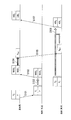
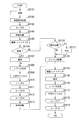
- FIG. 1 is a diagram showing an outline of an embodiment of the present invention.
- the horizontal axis is a time axis.
- the base station is a transmitting device
- a data signal P 1 and P 2 is an initial transmission packet via the downlink multiplexed as a downlink data signal to the terminal is a mobile station (step S101).
- Terminal receiving the signal through the time required for transmission, and stores the received signal signals P 1 and P 2 are multiplexed, perform interference cancellation process and a data detection process (step S102).
- the other multiplexed signal becomes an interference component.
- the interference cancellation process is a process for removing a signal (replica) obtained by reproducing an interference signal from a received signal. For example, when detecting the signal P 2 from the received signal, using a signal obtained by removing the replica of the signal P 1.
- the terminal generates a signal including success / failure information (NACK 1 , NACK 2 ) for reporting to the base station that an error has occurred in the packet of the signal P 1 and the signal P 2 , and transmits an uplink success / failure information signal as an uplink success / failure information signal. It transmits to a base station via a link (step S103).
- the base station that has received the uplink success / failure information signal generates a signal P N + 1 that is a retransmission packet for the signal P 1 that is a packet for which NACK is returned (step S104).
- the base station retransmits the signal P N + 1 as a downlink data signal to the terminal (step S105).
- the base station according to the embodiment of the present invention generates retransmission packets for some of the plurality of packets for which NACK is returned from the terminal, and transmits the retransmission packet to the terminal.
- the terminal that has received the downlink data signal demodulates the signal P N + 1 that is the retransmission packet, and uses the demodulation result of the signal P N + 1 and the received signal in which the stored signal P 1 and signal P 2 are multiplexed. Then, interference cancellation processing and data detection processing are performed (step S106).
- detection accuracy is improved by removing replicas of other multiplexed packets.
- HARQ hybrid automatic retransmission
- the terminal generates a signal including success / failure information (ACK 1 , ACK 2 ) for reporting to the base station that there is no error in the packets of signal P 1 and signal P 2 , and uplink success / failure via the uplink
- the information signal is transmitted to the base station (step S107).
- the base station that has received ACK 1 and ACK 2 does not need to perform retransmission corresponding to the signals P 1 and P 2 thereafter. Consequently, by retransmitting the signal P N + 1 corresponding to the signal P 1, to improve the error in both signals P 1 and P 2, without performing retransmission corresponding to the signal P 2, the signal P 1 and the signal data detection in P 2 becomes possible.
- a plurality of initial transmission packets are multiplexed and transmitted from a transmission device (also referred to as a base station) to a reception device (also referred to as a terminal), and data is removed while eliminating interference (other multiplexed packets) at the reception device. Is detected.
- data detection fails, a retransmission packet is transmitted from the transmission apparatus to the reception apparatus using a hybrid automatic retransmission (HARQ) method.
- HARQ hybrid automatic retransmission
- the receiving device fails to detect a plurality of multiplexed initial transmission packets and a retransmission packet corresponding to some of the packets is transmitted from the transmitting device, not only some packets but also the first detection In other initial transmission packets that failed to be detected again. If the detection is successful, information indicating successful detection is transmitted from the receiving device to the transmitting device. Thereby, since the number of downlink retransmission packets can be suppressed, throughput can be improved.
- a repetitive parallel MCI canceller is used on the receiving device side.
- the repetitive MCI canceller generates an MCI replica on the receiving side and subtracts the MCI replica from the received signal to suppress inter-code interference MCI.
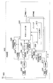
- FIG. 2 is a schematic block diagram showing the configuration of the transmission device 100 according to the first embodiment of the present invention.
- Transmitting apparatus 100 includes code channel signal generators 101-1 to 101-N (where N is the number of multiplexed codes), code multiplexer 102, interleaver 103, IFFT (Inverse Fast Fourier Transform) unit 104. , Pilot signal generation section 105, multiplexing section 106, GI (Guard Interval) insertion section 107, radio transmission section 108, antenna 109, radio reception section 110, separation section 111, retransmission control section 112, retransmission control signal generation section 113 is provided.
- Each of the code channel signal generation units 101-1 to 101-N includes a coding unit 114, a rate matching unit 115, a modulation unit 116, a spreading unit 117, and a coded bit storage unit 118.
- Code channel signal generation units 101-1 to 101-N (also referred to as transmission signal generation units) generate data signals for each code channel from information bits (transmission data).
- encoding section 114 performs channel encoding processing on the information bit sequence, and outputs the encoded bit sequence to rate match section 115 and encoded bit storage section 118.
- the encoding unit 114 preferably uses encoding having error correction capability such as convolutional encoding and Reed-Solomon encoding as channel encoding. More preferably, the encoding unit 114 may use encoding having high error correction capability such as turbo encoding and LDPC (Low Density Parity Check) encoding.
- the rate matching unit 115 punctures the encoded bits output from the encoding unit 114 or the encoded bits output from the encoded bit storage unit 118 according to the number of retransmissions output from the retransmission control unit 112 ( Bit removal), bit padding (bit insertion) or bit repetition (bit repetition) processing is performed, and the result is output to modulation section 116.
- the rate matching unit 115 further performs bit interleaving processing. An example of puncturing will be described later as an example of rate matching.
- the coded bit storage unit 118 (also referred to as a transmission data storage unit) stores a coded bit sequence that is an output of the coding unit 114. Also, the coded bit storage unit 118 erases the stored coded bit sequence based on the control of the retransmission control unit 112. Details of these processes will be described later. Note that the encoded bit storage unit 118 may store the information bits themselves instead of storing the output of the encoding unit 114.
- Modulating section 116 performs modulation processing on the coded bit (punctured coded bit) sequence output from rate matching section 115 and outputs the modulated symbol sequence to spreading section 117.
- the modulation unit 116 uses a modulation method such as PSK (Phase Shift Keying) or QAM (Quadrature Amplitude Modulation) as a modulation method.
- the modulation unit 116 may use a modulation scheme according to the propagation path between the transmission device 100 and the reception device 500.
- the code multiplexer 102 multiplexes the data signals for each code channel, which are the outputs of the code channel signal generators 101-1 to 101-N, and outputs the multiplexed data signals to the interleaver 103.
- Interleaver section 103 performs interleaving processing such as chip interleaving and symbol interleaving on the signal output from code multiplexing section 102 and outputs the result to IFFT section 104.
- the IFFT unit 104 performs IFFT processing on the signals arranged in the frequency direction, thereby converting the signals into a time domain signal and outputs the signals to the multiplexing unit 106.
- Pilot signal generating section 105 generates a pilot signal for use in propagation path estimation in receiving apparatus 500 (see FIG. 6), and outputs the pilot signal to multiplexing section 106.
- Retransmission control signal generation section 113 generates a signal (retransmission control signal) for notifying receiving apparatus 500 of the number of retransmissions of the signal of each code channel notified from retransmission control section 112, and outputs the signal to multiplexing section 106.
- Multiplexing section 106 multiplexes the data signal output from IFFT section 104, the pilot signal output from pilot signal generation section 105, and the retransmission control signal output from retransmission control signal generation section 113, and the GI insertion section It outputs to 107.
- the GI insertion unit 107 adds a guard interval to the signal output from the multiplexing unit 106 and outputs the signal to the wireless transmission unit 108.
- Radio transmitting section 108 (also referred to as transmitting section) performs processing such as up-conversion on the signal output from GI inserting section 107 and transmits the signal to receiving apparatus 500 via antenna 109.
- FIG. 3 is a schematic block diagram showing the configuration of the encoding unit 114 of the transmission device 100 (FIG. 2) according to the first embodiment of the present invention.
- the encoding unit 114 includes an inner encoder 201, an inner interleaver 202, and an inner encoder 203.
- turbo coding with a coding rate of 3 is used as channel coding will be described.
- the information bit sequence is the input information bit sequence itself.
- the first parity bit is an output result obtained by inputting an information bit sequence to the internal encoder 201 and performing an encoding process.
- the second parity bit is an output result obtained by interleaving the information bit sequence in the internal interleaver 202 and inputting the result of the interleaving process to the internal encoder 203 to perform the encoding process.
- the inner encoder 201 and the inner encoder 203 may be the same encoder or different encoders.
- a recursive convolutional encoder is used for both the inner encoder 201 and the inner encoder 203.
- the encoding unit 114 outputs three sequences, but may be output as one sequence by performing parallel-serial conversion.
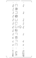
- FIG. 4 is a diagram illustrating an example of puncturing processing in the rate matching unit 115 of the transmission device 100 (FIG. 2) according to the first embodiment of the present invention.
- b s k is the kth information bit
- b p1 k is the kth first parity bit
- the puncture pattern A1 is a pattern indicating whether or not to perform puncturing (bit removal) for each encoded bit.
- a white square in FIG. 4 indicates that bits are not removed, and a black square indicates that bits are removed.
- the punctured coded bit B1 (b s k , b p1 k , b s k + 1 , b p2 k + 1 , b s k + 2 , b p1 k + 2 , b s k + 3 , b p2 k + 3 ,.
- FIG. 5 is a diagram illustrating a puncturing process when a puncture pattern (puncture pattern A2) different from that in FIG. 4 is used.
- the encoded bit D2 shown in the upper part of FIG. 5 is the same as the encoded bit D1 shown in the upper part of FIG. In this way, the rate matching unit 115 outputs different punctured encoded bits B1 by using different puncture patterns.
- the rate matching unit 115 generates the encoded bits D2 (b s k , b p1 k , b p2 k , b s k + 1 , b p1 k + 1 , b p2 k + 1 , b s k + 2 , b p1 k + 2 , b p2 k + 2 , b s k + 3 , b p1 k + 3 , b p2 k + 3 ,...) are punctured using the puncture pattern A2, and punctured coded bits B2 (b s k , b p2 k , b s k + 1 ,. b p1 k + 1 , b s k + 2 , b p2 k + 2 , b s k + 3 , b p1 k + 3 ,.
- the rate matching unit 115 Based on the control of the retransmission control unit 112, the rate matching unit 115 applies the coded bits that are output from the coding unit 114 or the coded bits that are output from the coded bit storage unit 118 as described above. Perform puncture processing.
- rate matching section 115 has a different puncture pattern applied to encoded bits that are output from encoding section 115 and a puncture pattern applied to encoded bits that are output from encoded bit storage section 118. It is good to puncture. More preferably, the puncture pattern applied to the encoded bits that are output from the encoding unit 114 is a pattern that does not remove information bits, and is applied to the encoded bits that are output from the encoded bit storage unit 118.
- a pattern that does not remove the removed bits in the puncture pattern applied to the encoded bits that are output from the encoding unit 115 may be used.
- the bits are always removed has been described, but the bits need not necessarily be removed. That is, a puncture pattern that does not remove bits may be used.
- FIG. 6 is a schematic block diagram showing the configuration of the receiving device 500 according to the first embodiment of the present invention.
- the receiving apparatus 500 includes an antenna 501, a radio reception unit 502, a separation unit 503, a propagation channel estimation unit 504, a propagation channel estimation value storage unit 505, a GI removal unit 506, an FFT unit 507, a reception signal storage unit 508, and a reception packet management unit. 509, interference canceller unit 510, code channel replica generation units 511-1 to 511-N, bit LLR (Log Likelihood Ratio) storage unit 512, success / failure information signal generation unit 513, multiplexing unit 514, radio transmission unit 515.
- LLR Log Likelihood Ratio
- Each of the code channel replica generation units 511-1 to 511-N includes a symbol replica generation unit 516 and a spreading unit 517.
- the wireless reception unit 502 receives a signal from the transmission device 100 via the antenna 501, performs processing such as down-conversion, and outputs the signal to the separation unit 503.
- Separating section 503 separates the signal output from radio receiving section 502 into a pilot signal, a retransmission control information signal, and a data signal.
- the propagation path estimation unit 504 estimates the propagation path characteristics between the transmission device 100 and the reception device 500 using the pilot signal separated in the separation unit 503, and the propagation path estimation value is used as the propagation path estimation value storage unit 505.
- the propagation path estimated value storage unit 505 stores the propagation path estimated value that is the output of the propagation path estimation unit 504.
- the GI removal unit 506 removes the guard interval from the data signal separated by the separation unit 503 and outputs the guard interval to the FFT unit 207.
- the FFT unit 507 converts the output signal of the GI removal unit 505 into a frequency domain signal by performing FFT processing, and outputs the signal to the reception signal storage unit 508 and the interference canceller 510.
- the reception signal storage unit 508 stores a frequency domain signal that is an output of the FFT unit 507.
- reception packet management section 509 Based on the retransmission control information signal separated by separation section 503 and the success / failure information output from interference canceller section 510, reception packet management section 509 has interference canceller section 510, bit LLR storage section 512, and received signal storage section 508. Various instructions are given to the propagation path estimated value storage unit 505. The received packet management unit 509 instructs the success / failure information signal generation unit 513 to generate a success / failure information signal. The detailed operation of the received packet management unit 509 will be described later.
- the interference canceller unit 510 detects an information bit sequence from the signal output from the FFT unit 507 while referring to the channel estimation value output from the channel estimation unit 504 based on an instruction from the received packet management unit 509.
- interference canceller section 510 outputs encoded bit LLR to code channel replica generation sections 511-1 to 511-N and outputs success / failure information to received packet management section 509.
- the bit LLR is output from the bit LLR storage unit 512
- the bit LLR and the propagation path estimated value that is the output of the propagation path estimated value storage unit 505 are obtained from the reception signal output from the reception signal storage unit 508. To detect information bits.
- a detailed example of the operation of the interference canceller unit 510 will be described later.
- Code channel replica generation units 511-1 to 511-N (also referred to as data signal replica generation units) generate replicas in code channels corresponding to spreading codes C 1 to C N.
- the symbol replica generation unit 516 generates a symbol replica based on the encoded bit LLR output from the interference canceller unit 510.
- the symbol replica output from the symbol replica generation unit 516 is duplicated by the spreading unit 517 by the spreading factor, and multiplied by spreading codes C 1 to C N in each code channel to generate a code channel replica (data signal replica). Is done.
- the bit LLR storage unit 512 stores the bit LLR output from the interference canceller unit 510 based on an instruction from the received packet management unit 509.
- the bit LLR storage unit 512 outputs the stored bit LLR to the interference canceller unit 510, and the bit LLR output from the interference canceller unit 510 again.
- the bit LLR storage unit 512 replaces the stored bit LLR with the newly output bit LLR.
- the success / failure information signal generation unit 513 generates a success / failure information signal based on an instruction from the received packet management unit 509 and outputs it to the multiplexing unit 514.
- the multiplexing unit 514 multiplexes the success / failure information signal output from the success / failure information signal generation unit 513 and the uplink data signal, and outputs the multiplexed data signal to the radio transmission unit 515.
- Radio transmitting section 515 (also referred to as report transmitting section) performs processing such as up-conversion on the signal output from multiplexing section 514 and transmits the signal to transmitting apparatus 100 (FIG. 2) via antenna 501.
- FIG. 7 is a schematic block diagram showing a main part 510a of the configuration of the repetitive parallel MCI interference canceller unit 510 according to the first embodiment of the present invention.
- a code channel signal corresponding to one spread code Ck is detected will be described.
- a series of processes in the interference canceller unit 510 is repeatedly executed except when all information bits can be detected without error for the first time.
- the main part 510a of the interference canceller unit 510 includes a propagation path compensation unit 601, a deinterleaver unit 602, a code separation unit 603, an MCI replica generation unit 604, and a subtraction unit 605 (also referred to as an interference removal unit).
- the code separation unit 603 includes a despreading unit 606, a demodulation unit 607, a rate matching unit 608, a synthesis unit 609, and a decoding unit 610 (also referred to as a determination unit).
- the MCI replica generation unit 604 (also referred to as interference signal replica generation unit) includes code channel replicas S r, 1 to S r, k ⁇ 1 , S r output from the code channel replica generation units 511-1 to 511-N. , K + 1 to Sr, N , code channel replicas other than Sr and k are input. Further, the MCI replica generation unit 604 receives the channel estimation value output from the channel estimation unit 504 (or the channel estimation value storage unit 505). The MCI replica generation unit 604 generates an MCI replica (interference replica) based on the code channel replica and the propagation path estimation value, and outputs the MCI replica to the subtraction unit 605.
- MCI replica interference replica
- FIG. 8 is a schematic block diagram showing the configuration of the MCI replica generation unit 604 (FIG. 7) according to the first embodiment of the present invention.
- the MCI replica generation unit 604 includes a code multiplexing unit 701, an interleaver unit 702, and a transfer function multiplication unit 703.
- the code multiplexing unit 701 multiplexes the code channel replicas S r, 1 , S r, k ⁇ 1 , S r, k + 1 , S r, N input to the MCI replica generation unit 604, and outputs them to the interleaver unit 702.
- Interleaver section 702 interleaves the signal output from code multiplexing section 701 and outputs the signal to transfer function multiplication section 703.
- the transfer function multiplying unit 703 multiplies the signal output from the interleaver unit 702 by a transfer function calculated from the propagation path estimated value (or the propagation path estimated value itself) to generate an MCI replica.
- the interleaver unit 702 performs the same processing as the interleaver unit 103, and thus can be realized by a similar circuit.
- the MCI replica generation unit 604 does not need to generate an MCI replica.
- the subtraction unit 605 subtracts the MCI replica from the output of the FFT unit 507 (or the received signal storage unit 508), and outputs the result to the propagation path compensation unit 601.
- the propagation path compensation unit 601 performs propagation path compensation on the output of the subtraction unit 605 based on the propagation path estimation value that is the output of the propagation path estimation unit 504 (or the propagation path estimation value storage unit 505), and deinterleaver. To the unit 602. Specifically, the propagation path compensation unit 601 performs processing for reproducing phase rotation and the like caused by the influence of the propagation path.
- the propagation path compensation unit 601 calculates an MRC weight, an ORC weight, or an MMSE (Minimum Mean Squared Error) weight from the propagation path estimation value, and multiplies the calculated weight with the output of the subtraction unit 605.
- MRC weight an ORC weight
- MMSE Minimum Mean Squared Error
- the deinterleaver unit 602 performs deinterleave processing on the output from the propagation path compensation unit 601 and outputs the result to the despreading unit 606.
- the order rearranged by the interleaving process in the interleaver unit 103 is rearranged so as to return to the original order.
- Despreading section 606, by performing despreading processing using a spreading code C k, it extracts a signal of a code channel corresponding to the spread code C k, the despread signal, and outputs to the demodulator 607.
- the diffusion coefficient C k is any one of the diffusion coefficients C 1 and C 2 to C N. It is possible to change the detection order of successive interference canceller by the selection of the diffusion coefficient C k.
- Demodulation section 607 performs demodulation processing on the despread modulation symbol sequence that is an output signal from despreading section 606, and extracts a signal for each bit. Then, demodulation section 607 outputs a log likelihood ratio (LLR) for each bit to rate matching section 608.
- LLR log likelihood ratio
- the propagation path compensation unit 601, the demodulation unit 607, and the rate matching unit 608 may be collectively referred to as a demodulation unit.
- a bit LLR an LLR for each bit
- bit sequence when the received signal S ′ is transmitted is b 0 , b 1 (b 0 , b 1 is 1 or ⁇ 1)
- the transmission signal S obtained by QPSK modulation of the bit sequences b 0 , b 1 is It can be expressed as equation (1).
- Equation (2) a bit LLR of b 0 ⁇ 1 (b 0) becomes Equation (2).
- the bit LLR of b 1 is obtained by exchanging the real part and the imaginary part of Equation (2).
- Re (x) represents the real part of the complex number x
- ⁇ is a value serving as a reference for the equivalent amplitude of the received signal, that is, the amplitude of the received signal.
- the symbol replica S r ′ is calculated by Expression (3).
- ⁇ 2 () is an output of the decoding unit 607.
- the rate matching unit 608 is the reverse of the puncturing (bit removal), bit padding (bit insertion), or bit repetition (bit repetition) processing performed in the rate matching unit 115 (FIG. 2) in the transmission apparatus 100. Process. That is, the rate matching unit 608 performs bit depuncturing (bit LLR insertion) processing on the punctured bits, performs bit removal processing on the bit padded (bit insertion) bits, Bit LLR synthesis is performed on repeated (bit repeated) bits.
- FIG. 9 is a diagram illustrating an example of the depuncturing process for the signal on which the puncturing process illustrated in FIG. 4 has been performed.
- d 1 s k , d 1 p1 k , d 1 s k + 1 , d 1 p2 k + 1 , d 1 s k + 2 , d 1 p1 k + 2 , d 1 s k + 3 , d 1 p2 k + 3 ,... are bits LLR ⁇ D3 .
- d 1 s k is the bit LLR of the kth information bit.
- d 1 p1 k is the bit LLR of the kth first parity bit.
- d 1 p2 k is the bit LLR of the k-th second parity bit.
- the puncture pattern A1 is a pattern indicating whether or not to perform puncturing (bit removal) for each encoded bit.
- a white square in FIG. 9 indicates that the bit is not removed, and a black square indicates that the bit is removed. 0 is inserted as the bit LLR in the removed bit.
- FIG. 10 is a diagram illustrating a depuncturing process when a puncture pattern A2 (puncture pattern A2 in FIG. 5) different from that in FIG. 9 is used.
- 0 is inserted as the bit LLR in the removed bit.
- the rate matching unit 608 inserts 0 as the bit LLR in the removed bit.
- rate matching section 608 outputs bit LLRs (including those that are 0) in all encoded bits.
- the rate matching unit 608 performs bit LLR ⁇ D4 (d 2 s k , d 2 p2 k , d 2 s k + 1 , d 2 p1 k + 1 , d 2 s k + 2 , d 2 p2 k + 2 , d 2 s k + 3 , d 2 p1 k + 3 ,...) is depunctured using the puncture pattern A2, and the depunctured bit LLR ⁇ E4 (d 2 s k , 0, d 2 p2 k , d 2 s k + 1 , d 2 p1 k + 1 , 0, d 2 s k + 2 , 0, d 2 p2 k + 2 , d 2 s k + 3 , d 2 p1 k + 3 , 0 ,.
- the combining unit 609 When it is the initial transmission packet or the first retransmission packet, the combining unit 609 outputs the bit LLR that is the output of the rate matching unit 608 as it is.
- the propagation path compensation unit 601, the demodulation unit 607, the rate matching unit 608, and the synthesis unit 609 may be collectively referred to as a signal synthesis unit.
- the combining unit 609 causes the bit LLR stored in the bit LLR storage unit 512 (the bit LLR in the corresponding initial transmission packet) and the bit LLR output from the rate matching unit 608. Are combined and output.
- the bit LLR output from the combining unit 609 is input to the decoding unit 610.
- the output bit LLR is output to the bit LLR storage unit 512.
- FIG. 11 is a diagram illustrating an example of bit LLR synthesis in the synthesis unit 609 according to the first embodiment of the present invention.
- FIG. 11 shows a case where the depunctured bit LLR shown in FIGS. 9 and 10 is synthesized.
- the decoding unit 610 performs a decoding process using the bit LLR output from the combining unit 609, information bit that is a decoding result, success / failure information indicating whether the information bit includes an error, encoded bit LLR, Is output.
- the decoding unit 610 outputs an encoded bit LLR without outputting an information bit when an error is included, and outputs an information bit without outputting an encoded bit LLR when there is no error. Also good.
- CRC Cyclic Redundancy Check
- error detection may be performed on the receiving apparatus 500 side.
- a signal transmitted from receiving apparatus 500 is received by radio receiving section 110 (also referred to as a report receiving section) via antenna 109.
- Separating section 111 separates the uplink data multiplexed on the received signal and the success / failure information.
- the retransmission control unit 112 prepares to transmit a retransmission packet (retransmission data signal) based on the success / failure information separated from the uplink data by the separation unit 111.
- the success / failure information is information (NACK) indicating reception failure
- the retransmission control unit 112 instructs the encoded bit storage unit 118 to output the encoded bit sequence corresponding to the packet for which the NACK is returned. To do. Further, retransmission control section 112 instructs rate matching section 115 to perform rate matching processing on the encoded bit sequence output from encoded bit storage section 118.
- the rate matching process may be the same as the initial transmission, but it is preferable to change the rate matching process according to the number of retransmissions.
- the retransmission control unit 112 notifies the retransmission control signal generation unit 113 of information indicating the number of retransmissions of the multiplexed packet.
- the retransmission control signal generation unit 113 generates a signal (retransmission control signal) indicating the information notified from the retransmission control unit 112 and outputs the signal to the multiplexing unit 106.
- the information indicating the number of retransmissions of the multiplexed packet is preferably information indicating the number of times itself, but may be information obtained by processing the number of retransmissions such as information indicating whether the transmission is the initial transmission or the retransmission.
- the success / failure information is information (ACK) indicating successful reception
- the retransmission control unit 112 stores a storage area in which the encoded bit sequence corresponding to the packet for which ACK is returned is stored in the encoded bit storage unit 118. Instruct to release.
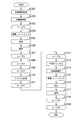
- FIG. 12 is a flowchart illustrating an example of processing for extracting information bits from an initial transmission packet included in a reception signal and control performed by the reception packet management unit 509 in the reception device 500.
- the wireless reception unit 502 receives a signal transmitted from the transmission device 100 (step S1101).
- the received signal is processed by the separating unit 503, the GI removing unit 506, and the FFT unit 507, and stored in the received signal storage unit 508 (step S1102).
- propagation path compensation is performed by the propagation path compensation section 601 using the propagation path estimation value estimated by the propagation path estimation section 504 (step S1103).
- step S1108 processing for each packet included in the received signal is performed. That is, the process of loop L1 (steps S1104 to S1108) regarding the packet included in the received signal is performed.
- the signal subjected to propagation path compensation in step S1103 is processed by the deinterleaver unit 602 and the despreading unit 606. Thereafter, demodulation processing and rate matching processing are performed in the demodulation unit 607 and the rate matching unit 608 (step S1105).
- the received packet management unit 509 determines whether or not it is the initial transmission (step S1106). If it is the first transmission (Yes in step S1106), decoding is performed by the decoding unit 610 using the bit LLR that is the result of the demodulation and rate matching processing (step S1107).
- the loop L2 process (steps S1109 to S1119) related to the repeated interference cancellation process is performed.
- processing for each initial transmission packet included in the received signal is performed. That is, the process of loop L3 (steps S1110 to S1112) regarding the initial transmission packet included in the received signal is performed.
- the code channel replica generation unit 511 generates a code channel replica of each initial transmission packet from the encoded bit LLR (step S1111).
- the second and subsequent detection processes are performed for each initial transmission packet included in the received signal. That is, the process of loop L4 (steps S1113 to S1118) regarding the initial transmission packet included in the received signal is performed. That is, the code channel replica (MCI replica) in the code channel other than the self code channel generated in step S1111 is canceled in the subtraction unit 605 (step S1114). Then, propagation path compensation is performed on the remaining signal by the propagation path compensation unit 601 (step S1115). Then, the demodulation unit 607 and the rate matching unit 608 perform demodulation and rate matching processing (step S1116). Then, decoding is performed by the decoding unit 610 (step S1117), and information bits are extracted from the initial transmission packet included in the received signal. However, in the cancellation of the code channel replica in step S1114, it is preferable to cancel the replica of the retransmission packet.
- the reception packet management unit 509 determines whether the retransmission is the first retransmission or the second or subsequent retransmission (step S1120). If it is the first retransmission (No in step S1120), the demodulated and rate-matched bit LLR is stored in the bit LLR storage unit 512 (step S1122). If it is the second and subsequent retransmissions (Yes in step S1120), the bit LLR subjected to demodulation and rate matching processing and the bit LLR stored in the bit LLR storage unit 512 are combined in the combining unit 609 (step S1121).
- bit LLR is stored in the bit LLR storage unit 512 (step S1122).
- bit LLR that has been subjected to demodulation and rate matching processing after repeated interference cancellation (the bit LLR at the subsequent stage of step S1116) may be stored in the bit LLR storage unit 512.
- the bit LLR may be decoded in step S1107 after step S1122 as shown in FIG. 12, or the decoding process in step S1107 may be omitted.
- step S1107 If decoding is not possible with only the retransmission packet, the decoding process in step S1107 may be omitted.
- the bit LLR stored in the bit LLR storage unit 512 is used in the process of extracting information bits from the initial transmission packet included in the past reception signal including the initial transmission packet corresponding to the retransmission packet.
- FIG. 13 is a flowchart showing an example of processing for extracting information bits from initial transmission packets included in past received signals including initial transmission packets corresponding to retransmission packets and control performed by the reception packet management unit 509 (FIG. 6). It is.
- the interference canceller unit 510 acquires a past received signal including an initial transmission packet corresponding to a retransmission packet from the received signal storage unit 508 (step S1201).
- the propagation path compensation unit 601 performs propagation path compensation using the propagation path estimation value stored in the propagation path estimation value storage unit 505 when the received signal is received (step S1202). Note that a reception signal that has been subjected to propagation path compensation may be stored. In this case, the propagation path compensation here may not be performed.
- loop L5 processing (steps S1203 to S1207) regarding the initial transmission packet corresponding to the retransmission packet is performed.
- the initial transmission packet first, the signal subjected to propagation path compensation is processed by the deinterleaver unit 602 and the despreading unit 606. Demodulation and rate matching processing is performed in demodulation section 607 and rate matching section 608 (step S1204), and coded bit LLR is obtained.
- the combining unit 609 combines the coded bit LLR obtained in step S1204 and the coded bit LLR of the retransmission packet corresponding to the initial transmission packet (the bit LLR stored in step S1122 in FIG. 12). (Step S1205). Then, the decoding unit 610 performs decoding using the encoded bit LLR obtained by the synthesis (step S1206).
- step S1208 to S1219 is performed.
- processing is performed on each initial transmission packet included in a past received signal. That is, the process of loop L7 (steps S1209 to S1211) regarding the initial transmission packet included in the received signal is performed.
- the code channel replica generation unit 511 generates a code channel replica of each initial transmission packet from the encoded bit LLR (or the encoded bit LLR in the case of being combined in step 1205).
- the second and subsequent detection processes are performed for each initial transmission packet included in the past received signal. That is, the process of loop L8 (steps S1212 to S1218) regarding the initial transmission packet included in the received signal is performed. That is, the code channel replica in the code channel other than the self code channel generated in step S1210 is canceled in the subtracting unit 605 (step S1213). Then, propagation path compensation is performed on the remaining signal by the propagation path compensation unit 601 (step S1214). Demodulation section 607 and rate matching section 608 perform demodulation and rate matching processing (step S1215) to calculate coded bit LLR.
- the calculated encoded bit LLR and the encoded bit LLR of the retransmission packet are combined by the combining unit 609 (step S1216).
- the decoding unit 610 performs decoding using the combined encoded bit LLR (step S1217).
- information bits are extracted from the initial transmission packet included in the past received signal.
- the cancellation of the code channel replica in step S1213 preferably cancels the replica of the retransmission packet included in the past received signal.
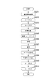
- FIG. 14 is a diagram illustrating an example of a flow of a series of processes of detection of received data, report of success / failure information, retransmission, and redetection of received data.
- the base station which is a transmission device, multiplexes signals P 1 to P N that are initial transmission packets via the downlink, and transmits the multiplexed data as downlink data signals to the terminal that is a reception device (step S201).
- the terminal that has received the signal stores the received signal in which the signals P 1 to P N are multiplexed, and performs interference cancellation processing and data detection processing (step S202).
- interference cancellation processing and data detection processing step S202
- the terminal generates a signal including success / failure information (NACK 1 to NACK N ) for reporting to the base station that an error has occurred in the packets of the signals P 1 to P N. Then, the terminal transmits the generated signal as an uplink success / failure information signal to the base station via the uplink (step S203).
- the base station that has received the success / failure information signal generates a retransmission packet (signal P N + 1 ) for the packet (signal P 1 ) for which NACK is returned (step S204). Then, the base station multiplexes the generated retransmission packet (signal P N + 1 ) with other downlink packets (signals P N + 2 to P 2N ), and transmits the multiplexed packets to the terminal as downlink data signals (steps S205 and S206). ). The base station only needs to generate and transmit retransmission packets for some of the packets for which NACK is returned.
- the terminal that has received the downlink data signal performs interference cancellation processing and data detection processing on the signals P N + 2 to P 2N .
- the terminal generates a signal including success / failure information (ACK N + 2 to ACK 2N ) for reporting to the base station that there is no error in the packets of the signals P N + 2 to P 2N (step S207).
- the terminal transmits the generated signal as an uplink success / failure information signal to the base station via the uplink (step S208).
- ACK need not be transmitted.
- the terminal performs interference cancellation processing and data detection processing using the demodulation result of the retransmission packet (signal P N + 1 ) and the received signal in which the stored signals P 1 to P N are multiplexed (step S209).
- the detection accuracy is improved by previously removing replicas of other previously multiplexed packets. That is, by combining the retransmission packet (by combining the signal P 1 that is the signal packet and the signal P N + 1 that is the retransmission packet), the detection accuracy of the signal P 1 is improved from the time of detection of the initial transmission, As the accuracy of the replica of P 1 is improved, the detection accuracy of the signals P 2 to P N is also improved.
- the terminal generates a signal including success / failure information (ACK 1 to ACK N ) for reporting to the base station that there is no error in the packets of the signals P 1 to P N , and uses the uplink as a success / failure information signal via the uplink.
- ACK 1 to ACK N success / failure information
- the base station that has received ACK 1 to ACK N does not need to perform retransmission corresponding to the packets (signals P 1 to P N ) thereafter.
- P N + 1 corresponding to the signal P 1 errors in the packets (signals P 1 to P N ) are improved, and without performing retransmission corresponding to the packets (signals P 2 to P N ).
- the data in the packets (signals P 1 to P N ) can be detected.
- FIG. 15 is a diagram illustrating another example of a flow of a series of processes of detection of received data, report of success / failure information, and retransmission and redetection of received data.
- the base station multiplexes the signals P 1 to P N that are initial transmission packets via the downlink, and transmits them to the terminal as downlink data signals (step S301).
- the terminal receiving the signal stores the received signal in which the signals P 1 to P N are multiplexed. Then, the terminal performs interference cancellation processing and data detection processing.
- a case where an error occurs in all packets of signals P 1 to P N will be described.
- the terminal generates a signal including success / failure information (NACK 1 to NACK N ) for reporting to the base station that an error has occurred in the packets of signals P 1 to P N (step S302). Then, the terminal transmits the generated signal as an uplink success / failure information signal to the base station via the uplink (step S303).
- the base station that has received the uplink success / failure information signal generates a retransmission packet (signal P N + 1 ) for the packet (signal P 1 ) for which NACK is returned (step S304). Then, the base station multiplexes the generated signal with a downlink packet as a downlink data signal and transmits it to the terminal (step S305). The base station only needs to generate and transmit retransmission packets for some of the packets for which NACK is returned. Since the other packets to be multiplexed are the same as those described with reference to FIG. 14, the description thereof is omitted here.
- the terminal that has received the downlink data signal stores the demodulation result of the retransmission packet (signal P N + 1 ). Further, the terminal performs interference cancellation processing and data detection processing using the demodulation result of signal P N + 1 and the received signal in which stored signals P 1 to P N are multiplexed.
- the terminal performs interference cancellation processing and data detection processing using the demodulation result of signal P N + 1 and the received signal in which stored signals P 1 to P N are multiplexed.
- the terminal generates a signal including success / failure information (NACK 1 to NACK N ) for reporting to the base station that an error has occurred in the packets of signals P 1 to P N (step S306). Then, the terminal transmits the generated signal as an uplink success / failure information signal to the base station via the uplink (step S307).
- success / failure information NACK 1 to NACK N
- the success / failure information for the second and subsequent times does not necessarily have to be transmitted to the base station.
- the base station as a transmitting device may perform the processing as if it received NACK unless ACK is returned.
- uplink overhead can be reduced.
- the base station that has received the uplink success / failure information signal generates a second retransmission packet (signal P N + 2 ) for the packet (signal P 1 ) for which NACK is returned (step S308). Then, the base station multiplexes the generated signal with other downlink packets and transmits them to the terminal (step S309).
- the terminal that has received the downlink signal combines the demodulation result of the retransmission packet (signal P N + 2 ) with the stored demodulation result of (signal P N + 1 ). Then, the terminal performs interference cancellation processing and data detection processing using the synthesized result and the received signal in which the stored signals P 1 to P N are multiplexed.
- the terminal generates a signal including success / failure information (ACK 1 to ACK N ) for reporting to the base station that there are no errors in the packets of the signals P 1 to P N (step S310). Then, the terminal transmits the generated signal as an uplink success / failure information signal to the base station via the uplink (step S311).
- the base station that has received ACK 1 to ACK N does not need to perform retransmission corresponding to the packets (signals P 1 to P N ) thereafter. Consequently, by retransmitting the signal P N + 1 and the signal P N + 2 corresponding to the signal P 1 from the base station to the terminal, it is possible to improve the error in the packet (signal P 1 ⁇ P N). Then, it is possible to detect data in the packets (signals P 1 to P N ) without performing retransmission corresponding to the packets (signals P 2 to P N ).
- FIG. 16 is a diagram illustrating another example of a flow of a series of processing of detection of received data, report of success / failure information, and retransmission and redetection of received data.
- the base station multiplexes signals P 1 to P N that are initial transmission packets via the downlink, and transmits them to the terminal as downlink data signals (step S401).
- the terminal receiving the signal stores the received signal in which the signals P 1 to P N are multiplexed. Then, the terminal performs interference cancellation processing and data detection processing.
- a case where an error occurs in all packets of signals P 1 to P N will be described.
- the terminal generates a signal including success / failure information (NACK 1 to NACK N ) for reporting to the base station that an error has occurred in the packets of signals P 1 to P N (step S402). Then, the terminal transmits the generated signal as an uplink success / failure information signal to the base station via the uplink (step S403).
- the base station that has received the uplink success / failure information signal generates a retransmission packet (signal P N + 1 ) for the packet (signal P 1 ) for which NACK is returned (step S404). Then, the base station multiplexes the generated signal with other downlink packets and transmits them to the terminal as downlink data signals (step S405).
- the base station only needs to generate and transmit retransmission packets for some of the packets for which NACK is returned. Since the other packets to be multiplexed are the same as those described with reference to FIG. 14, the description thereof is omitted here.
- the terminal that has received the downlink signal stores the demodulation result of the retransmission packet (signal P N + 1 ). Further, the terminal performs interference cancellation processing and data detection processing using the demodulation result of signal P N + 1 and the received signal in which stored signals P 1 to P N are multiplexed.
- the terminal performs interference cancellation processing and data detection processing using the demodulation result of signal P N + 1 and the received signal in which stored signals P 1 to P N are multiplexed.
- the terminal generates a signal including success / failure information (NACK 1 to NACK N ) for reporting to the base station that an error has occurred in the packets of signals P 1 to P N (step S406). Then, the terminal transmits the generated signal as an uplink success / failure information signal to the base station via the uplink (step S407).
- success / failure information NACK 1 to NACK N
- the success / failure information for the second and subsequent times does not necessarily have to be transmitted.
- the base station After transmitting the retransmission packet (signal P N + 1 ) to the terminal, the base station generates a retransmission packet (signal P N + 2 ) for the packet (signal P 1 ) for which NACK is returned (step S408). Then, the base station multiplexes the generated signal with another downlink packet and transmits it to the terminal as a downlink data signal (step S409).
- the terminal that has received the downlink signal uses the demodulation result of the retransmission packet (signal P N + 2 ), the stored signal P N + 1, and the received signal in which the stored signals P 1 to P N are multiplexed. Interference cancellation processing and data detection processing are performed.
- a case where there is no error in all the packets of signals P 1 to P N will be described.
- the terminal generates a signal including success / failure information (ACK 1 to ACK N ) for reporting to the base station that there are no errors in the packets of the signals P 1 to P N (step S410). Then, the terminal transmits the generated signal as an uplink success / failure information signal to the base station via the uplink (step S411).
- the base station that has received ACK 1 to ACK N does not need to perform retransmission corresponding to the packets (signals P 1 to P N ) thereafter. Consequently, by retransmitting the signal P N + 2 corresponding to the signal P N + 1 and the signal P 2 corresponding to the signal P 1, it is possible to improve the error in the packet (signal P 1 ⁇ P N). Then, it is possible to detect data in the packets (signals P 1 to P N ) without performing retransmission corresponding to the packets (signals P 3 to P N ).
- the received packet management unit 509 receives information (for example, a number corresponding to a received frame) that specifies a received signal (received frame) received at each reception timing, and information (for example, a packet that is included in each received signal). Corresponding number), information indicating the number of retransmissions of each packet, and information designating the bit LLR of the retransmission packet corresponding to each packet.
- received packet management section 509 When receiving apparatus 500 receives a received signal, received packet management section 509 notifies received signal storage section 508 and propagation path estimated value storage section 505 of information specifying the received signal.
- the reception signal storage unit 508 stores the reception signal itself in association with information specifying the reception signal.
- the propagation path estimated value storage unit 505 stores a propagation path estimated value corresponding to the received signal in association with information specifying the received signal.
- the received packet management unit 509 receives information specifying the received signal including the initial transmission packet corresponding to the retransmission packet from the received signal storage unit 508 and propagation path estimation.
- the value storage unit 505 is notified.
- reception signal storage unit 508 When the reception signal storage unit 508 is notified of information specifying a reception signal from the reception packet management unit 509, the reception signal storage unit 508 outputs a reception signal associated with the information to the interference canceller unit 510. In addition, when information specifying a received signal is notified from received packet management section 509, propagation path estimated value storage section 505 outputs a propagation path estimated value associated with the information to interference canceller section 510.
- received packet management section 509 refers to the number of retransmissions of the packet included in the received signal. Then, when there is a packet whose retransmission count is two or more, received packet management section 509 notifies bit LLR storage section 512 of information specifying the bit LLR of the retransmission packet corresponding to the packet. .
- the bit LLR storage unit 512 outputs the stored bit LLR to the interference canceller unit 510 based on the notified information. Further, when there is a packet whose number of retransmissions is 1, the received packet management unit 509 generates information specifying the bit LLR of the retransmission packet corresponding to the packet, and notifies the bit LLR storage unit 512 of the information. The bit LLR storage unit 512 stores the bit LLR output from the interference canceller unit 510 in association with the notified information.
- Received packet management section 509 notifies interference canceller section 510 of information specifying a packet included in the received signal and information indicating the number of retransmissions of each packet.
- Interference canceller section 510 determines a pattern to be used for depuncture processing in rate match section 608 from information specifying packets included in the received signal and information indicating the number of retransmissions of each packet.
- combining section 609 does not perform combining and outputs the signal output from rate matching section 608 to decoding section 610 as it is.
- the synthesis unit 609 does not perform synthesis and outputs the signal output from the rate matching unit 608 to the bit LLR storage unit 512 as it is.
- combining section 609 When the number of retransmissions is 2 or more, combining section 609 combines the signal output from rate matching section 608 and the signal stored in bit LLR storage section 512 and outputs the combined signal to bit LLR storage section 512.
- received packet management section 509 When re-detecting a packet included in a received signal stored at the time of receiving a retransmission packet, received packet management section 509 notifies bit LLR storage section 512 of information specifying the bit LLR of the retransmission packet corresponding to the packet. To do.
- the bit LLR storage unit 512 outputs the bit LLR associated with the notified information to the interference canceller unit 510.
- received packet management section 509 interferes with information specifying a packet included in the received signal to be detected again and information specifying the number of retransmissions. Notify the canceller unit 510.
- Interference canceller section 510 combines bits LLR in combining section 609 for packets with a retransmission count of 1 or more, and does not combine packets with a retransmission count of 0.
- a plurality of initial transmission packets are multiplexed and transmitted from the transmission device 100 to the reception device 500, and data is detected while removing interference (other multiplexed packets) in the reception device 500.
- the data detection fails, the retransmission packet is transmitted from the transmission device 100 to the reception device 500.
- a plurality of multiplexed initial transmission packets fail to be detected and retransmission packets corresponding to some of the packets are transmitted, not only some of the packets but also other initial transmissions that failed to be detected for the first time. If the packet is detected again and the detection is successful, information indicating the detection success is transmitted to the transmission device 100. Thereby, since the number of downlink retransmission packets can be suppressed, throughput is improved.
- FIG. 17 is a schematic block diagram showing a configuration of a receiving device 1600 according to the second embodiment of the present invention.
- the transmitting apparatus can be realized with the same configuration as the transmitting apparatus 100 shown in FIG.
- a receiving apparatus 1600 includes an antenna 1601, a radio reception unit 1602, a separation unit 1603, a propagation path estimation unit 1604, a propagation path estimation value storage unit 1605, a GI removal unit 1606, an FFT unit 1607, a received signal storage unit 1608, and a received packet management unit. 1609, an interference canceller unit 1610, a bit LLR storage unit 1612, a success / failure information signal generation unit 1613, a multiplexing unit 1614, and a wireless transmission unit 1615. Since blocks other than the interference canceller unit 1610 can use the same blocks as the blocks having the same names shown in FIG. 6, processing performed by the interference canceller unit 1610 will be described below.
- FIG. 18 is a schematic block diagram illustrating a configuration of the interference canceller unit 1610 of the reception device 1600 according to the second embodiment of the present invention.
- code channel signals corresponding to spreading codes C 1 to C N are sequentially detected in the order of C 1 , C 2 , C 3 to C N.
- a series of processing in the interference canceller unit 1610 is repeatedly executed. The number of repetitions is one or more.
- the interference canceller unit 1610 includes propagation path compensation units 1701-1 and 1701-2 to 1701-N, deinterleaver units 1702-1 and 1702-2 to 1702-N, and code separation units 1703-1 and 1702-3 to 1703. N, MCI replica generation units 1704-1, 1704-2, 1704-3 to 1704-N, code channel replica generation units 1705-1, 1705-2 to 1705-N (not shown), and subtraction units 1706-1, 1706 -2 to 1706-N.
- the code separation unit 1703-1 includes a despreading unit 1707-1, a demodulation unit 1708-1, a rate matching unit 1709-1, a combining unit 1710-1, and a decoding 1711-1.
- the code separation units 1703-2 to 1703-N have the same configuration as the code separation unit 1703-1.
- a plurality of blocks having the same function are shown redundantly, but only one block may be provided and the function of the block may be used a plurality of times.
- Each block in the interference canceller unit 1610 performs the same processing as each block of the same name in the interference canceller unit 510 shown in FIG. Further, code channel replica generation units 1705-1 to 1705-N perform the same processing as code channel replica generation unit 511 in receiving apparatus 500. Therefore, here, the difference between the processing of the interference canceller unit 1610 and the processing of the interference canceller unit 510 will be described.
- the interference canceller unit 510 performs signal detection for each code channel corresponding to the spreading codes C 1 to C N , and the code channel replica generation unit 511 performs each code corresponding to the spreading codes C 1 to C N. A channel replica was generated. The generated code channel replica is used for interference cancellation at the next iteration in the interference canceller unit 510.
- the interference canceller unit 1610 in this embodiment includes code channel replica generation units 1705-1 to 1705-N. Then, every time signal detection of any code channel corresponding to spreading codes C 1 to C N is completed, code channel replica generation sections 1705-1 to 1705-N generate or update code channel replicas. Then, the generated or updated code channel replica is used for interference cancellation in the code channel to be detected next.
- the code channel replica is updated after the signal detection of all code channels of the spreading codes C 1 to C N.
- the code channel replica is updated after the signal of one code channel is detected. Therefore, a highly accurate code channel replica can be generated.
- HARQ processing similar to that of the first embodiment can be performed.
- a plurality of initial transmission packets are multiplexed and transmitted from the transmission device 100 (FIG. 2) to the reception device 1600 (FIG. 17).
- the receiving device 1600 detects data while removing interference (other multiplexed packets).
- data detection fails, a retransmission packet is transmitted from the transmission device 100 to the reception device 1600.
- a plurality of multiplexed initial transmission packets fail to be detected and retransmission packets corresponding to some of the packets are transmitted from the transmission apparatus 100 to the reception apparatus 1600, not only the partial packets but also the initial transmission packets are transmitted.
- the receiving apparatus 1600 again detects another initial transmission packet that fails to be detected. If the detection is successful, information indicating successful detection is transmitted to the transmission device 100. Thereby, since the number of downlink retransmission packets can be suppressed, throughput is improved.
- FIG. 19 is a schematic block diagram showing a configuration of a transmission device 1800 according to the third embodiment of the present invention.
- Transmission apparatus 1800 includes stream signal generation sections 1801-1 to 1801-N (where N is the number of streams), antennas 1809-1 to 1809-N, radio reception section 1810, separation section 1811, retransmission control section 1812, and retransmission control.
- a signal generation unit 1813 is provided.
- the stream signal generation units 1801-1 to 1801-N are respectively an encoding unit 1814, a rate matching unit 1815, a modulation unit 1816, an interleaver unit 1803, an IFFT unit 1804, a pilot signal generation unit 1805, a multiplexing unit 1806, a GI insertion unit 1807, A wireless transmission unit 1808 and an encoded bit storage unit 1818 are provided.
- the stream signal generation unit 1801-1 generates a transmission data signal for each stream from the information bits.
- the encoding unit 1814 performs channel encoding processing on the information bit sequence, and outputs the encoded bit sequence to the rate matching unit 1815 and the encoded bit storage unit 1818.
- the coding unit 1814 preferably uses coding having error correction capability such as convolution coding and Reed-Solomon coding as channel coding. More preferably, the encoding unit 1814 may use encoding having high error correction capability such as turbo encoding or LDPC encoding.
- the rate matching unit 1815 punctures the encoded bits output from the encoding unit 1814 or the encoded bits output from the encoded bit storage unit 1818 according to the number of retransmissions output from the retransmission control unit 1812 ( Bit removal), bit padding (bit insertion) or bit repetition (bit repetition) processing is performed.
- the rate matching unit 1815 may further perform bit interleaving processing. An example of puncturing will be described later as an example of rate matching.
- the coded bit storage unit 1818 stores a coded bit sequence that is an output of the coding unit 1814. Further, based on the control of retransmission control section 1812, the stored coded bit sequence is erased.
- Modulation section 1816 performs modulation processing on the encoded bit (punctured encoded bit) sequence output from rate match section 1815, and outputs the modulated symbol sequence to interleaver section 1803.
- the modulation unit 1816 can use a modulation method such as PSK or QAM as a modulation method. More preferably, a modulation scheme according to the propagation path between the transmission apparatus 1800 and the reception apparatus 1900 (see FIG. 20) is used.
- Interleaver section 1803 performs interleaving processing such as symbol interleaving (frequency interleaving) on the signal output from modulation section 1816 and outputs the result to IFFT section 1804.
- the IFFT unit 1804 performs IFFT processing on the signals arranged in the frequency direction, thereby converting the signals into a time domain signal and outputs the signals to the multiplexing unit 1806.
- Pilot signal generation section 1805 generates a pilot signal for use in propagation path estimation in receiving apparatus 1900 and outputs the pilot signal to multiplexing section 1806.
- pilot signal generation section 1805 Preferably, pilot signal generation section 1805 generates orthogonal pilot signals for each stream.
- the retransmission control signal generation unit 1813 generates a signal (retransmission control signal) for notifying the reception device 1900 of the number of retransmissions of the data signal of each stream notified from the retransmission control unit 1812, and outputs the signal to the multiplexing unit 1806.
- the retransmission control signal is configured to be multiplexed into the stream in the stream signal generation unit 1801-1, but is not limited thereto. It may be multiplexed on any stream (s).
- Multiplexing section 1806 multiplexes the data signal output from IFFT section 1804, the pilot signal output from pilot signal generation section 1805, and the retransmission control signal output from retransmission control signal generation section 1813, and the GI insertion section 1807 is output.
- the GI insertion unit 1807 adds a guard interval to the signal output from the multiplexing unit 1806 and outputs the signal to the radio transmission unit 1808.
- Radio transmission section 1808 performs processing such as up-conversion on the signal output from GI insertion section 1807 and transmits the signal to reception apparatus 1900 via antenna 1809-1.
- the other stream signal generation units 1801-2 to 1801-N and the antennas 1809-2 to 1809-N perform the same processing as the stream signal generation unit 1801-1 and the antenna 1809-1.
- FIG. 20 is a schematic block diagram illustrating a configuration of a reception device 1900 according to the third embodiment of the present invention.
- Reception apparatus 1900 includes antennas 1901-1 to 1901 -M (where M is the number of reception antennas), reception processing units for each antenna 1902-1 to 1902-M, received packet management unit 1910, interference canceller unit 1911, and bit LLR storage.
- the reception processing units 1902-1 to 1902-M for each antenna respectively include a wireless reception unit 1903, a separation unit 1904, a propagation path estimation unit 1905, a propagation path estimation value storage unit 1906, a GI removal unit 1907, an FFT unit 1908, and a reception signal storage. Part 1909 is provided.
- the propagation path estimation unit 1905 to the bit LLR storage unit 1912 are collectively referred to as a data signal detection unit.
- Radio reception section 1903 (also referred to as a reception section) performs processing such as down-conversion on the signals received by antennas 1901-1 to 1901-M, and outputs the result to demultiplexing section 1904.
- Separating section 1904 separates the signal output from radio receiving section 1903 into a pilot signal, a retransmission control information signal, and a data signal.
- Propagation path estimation section 1905 uses the pilot signal separated in demultiplexing section 1904, between each antenna 1809-1 to 1809-N of transmitting apparatus 1800 and antenna 1901-1 to 1901-M of receiving apparatus 1900.
- the propagation path characteristic is estimated, and the propagation path estimated value is output to the propagation path estimated value storage unit 1906 and the interference canceller unit 1911.
- the propagation path estimated value storage unit 1906 stores the propagation path estimated value that is the output of the propagation path estimation unit 1905.
- the GI removal unit 1907 removes the guard interval from the data signal separated by the separation unit 1904 and outputs it to the FFT unit 1908.
- the FFT unit 1908 performs FFT processing on the output signal of the GI removal unit 1907 to convert it into a frequency domain signal, and outputs it to the received signal storage unit 1909 and the interference canceller unit 1911.
- the reception signal storage unit 1909 stores a frequency domain signal that is an output of the FFT unit 1909.
- the reception packet management unit 1910 includes an interference canceller unit 1911, a bit LLR storage unit 1912, and a reception signal storage unit 1909 based on the retransmission control information signal separated by the separation unit 1904 and the success / failure information output from the interference canceller unit 1911.
- Various instructions are given to the propagation path estimated value storage unit 1906.
- the received packet management unit 1910 instructs the success / failure information signal generation unit 1913 to generate a success / failure information signal. The detailed operation of the received packet management unit 1910 will be described later.
- the interference canceller unit 1911 outputs from the reception processing units 1902-1 to 1902-M for each antenna while referring to the propagation path estimation value output from the propagation path estimation unit 1905 based on the instruction of the received packet management unit 1910.
- the information bit sequence is detected from the received signal and the success / failure information is output to the received packet management unit 1910.
- the interference canceller unit 1911 outputs the bit LLR and the propagation path estimated value storage unit 1906 from the reception signal output from the reception signal storage unit 1909. Information bits are detected using the propagation path estimation value. A detailed example of the operation of the interference canceller unit 1911 will be described later.
- the bit LLR storage unit 1912 stores the bit LLR output from the interference canceller unit 1911 based on an instruction from the received packet management unit 1910. If the retransmission packet is multiplexed with the received signal, the bit LLR storage unit 1912 outputs the stored bit LLR to the interference canceller unit 1911 and the bit LLR output from the interference canceller unit 1911 again. Remember. That is, the bit LLR storage unit 1912 replaces the stored bit LLR with the newly output bit LLR.
- the success / failure information signal generation unit 1913 generates a success / failure information signal based on an instruction from the received packet management unit 1910 and outputs the success / failure information signal to the multiplexing unit 1914.
- the multiplexing unit 1914 multiplexes the success / failure information signal that is the output of the success / failure information signal generation unit 1913 and the uplink data signal, and outputs the multiplexed result to the radio transmission unit 1915.
- Radio transmission section 1915 (also referred to as report transmission section) performs processing such as up-conversion on the signal output from multiplexing section 1914 and transmits the signal to transmission apparatus 1800 via antenna 1901-1. Note that, here, an example in which an uplink signal is transmitted from only the antenna 1901-1 will be described, but the present invention is not limited to this. Uplink signals may be transmitted using a plurality of antennas.
- FIG. 21 is a schematic block diagram showing the configuration of the interference canceller unit 1911 of the receiving apparatus 1900 according to the third embodiment of the present invention.
- a series of processing in the interference canceller unit 1911 is repeatedly executed except when all information bits can be detected without error for the first time.
- the interference canceller unit 1911 includes a stream detection unit 2001-1, 2001-2 to 2001-N, a reception replica generation unit 2002-1, 2002-2, 2002-3 to 2002-N, and a subtraction unit 2003-1, 2003-2. To 2003-N, symbol replica generation units 2004-1, and 2004-2 to 2004-N (not shown).
- the stream detection unit 2001-1 includes a MIMO separation unit 2005-1 (also referred to as a stream separation unit), a deinterleaver unit 2006-1, a demodulation unit 2007-1, a rate matching unit 2008-1, a synthesis unit 2009-1, and a decoding unit. 2010-1 is provided.
- the stream detection units 2001-2 to 2001 -N also have the same configuration as the stream detection unit 2001-1.
- Reception replica generation units 2002-1 to 2002-N receive symbol channel replicas S r, 1 to S r, N output from symbol replica generation units 2004-1 to 2004- N .
- a stream replica (interference replica) is generated based on the symbol replicas other than S r and k and the channel estimation value output from the channel estimation unit 1905 (or channel estimation value storage unit 1906). Output to the subtracting units 2003-1 to 2003-N. Note that at the first time, the reception replica generation units 2002-1 to 2002-N do not need to generate a reception replica. In addition, the symbol replica that is generated or updated last is used for each symbol replica during the repetition.
- Subtraction units 2003-1 to 2003-N subtract the stream replica from the output of FFT unit 1908 (or received signal storage unit 1909), and output the result to MIMO separation units 2005-1 to 2005-N.
- MIMO demultiplexing sections 2005-1 to 2005-N output from subtraction sections 2003-1 to 2003-N based on the propagation path estimated value that is the output of propagation path estimating section 1905 (or propagation path estimated value storage section 1906). are subjected to MIMO stream separation and output to the deinterleaver units 2006-1 to 2006-N. Specifically, MIMO separation sections 2005-1 to 2005-N reproduce the stream data signal by maximum likelihood estimation.
- MIMO separation sections 2005-1 to 2005-N calculate MMSE weights for the outputs of subtraction sections 2003-1 to 2003-N, and the calculated weights are output to the outputs of subtraction sections 2003-1 to 2003-N.
- a separation method such as multiplication is used.
- Deinterleaver units 2006-1 to 2006-N perform deinterleave processing on the outputs from MIMO demultiplexing units 2005-1 to 2005-N, and output them to demodulation units 2007-1 to 2007-N.
- This deinterleaving process is preferably rearrangement that restores the order rearranged by the interleaving process in the interleaver unit 1803.
- Demodulating sections 2007-1 to 2007-N perform demodulation processing on the modulation symbol sequences that are output signals from deinterleaver sections 2006-1 to 2006-N, and extract a signal for each bit.
- demodulation sections 2007-1 to 2007-N output a log likelihood ratio (LLR) for each bit to rate matching sections 2008-1 to 2008-N.
- LLR log likelihood ratio
- the MIMO separation units 2005-1 to 2005-N, the deinterleaver units 2006-1 to 2006-N, the demodulation units 2007-1 to 2007-N, and the rate matching units 2008-1 to 2008-N are combined into a demodulation unit. Sometimes called.
- the rate matching units 2008-1 to 2008-N perform puncturing (bit removal), bit padding (bit insertion), or bit repetition (bit repetition) processing performed by the rate matching unit 1815 in the transmission apparatus 1800.
- the reverse process is performed, and the result is output to the synthesis units 2009-1 to 2009-N. That is, rate matching sections 2008-1 to 2008-N perform bit depuncturing (bit LLR insertion) processing on punctured bits, and bit padding (bit insertion) on bits. Removal processing is performed, and bit LLR synthesis is performed on the bits that have been bit-repeated (bit repetition).
- MIMO separation units 2005-1 to 2005-N, deinterleaver units 2006-1 to 2006-N, demodulation units 2007-1 to 2007-N, rate matching units 2008-1 to 2008-N, and synthesis unit 2009-1 To 2009-N may be collectively referred to as a signal synthesis unit.
- the bit LLR (bit LLR in the corresponding initial transmission packet) stored in the bit LLR storage unit 1812 and the rate matching unit
- the bit LLR that is the output of 2008-1 to 2008-N is synthesized and output.
- Bit LLRs output from combining sections 2009-1 to 2009-N are input to decoding sections 2010-1 to 2010-N. Further, the combining units 2009-1 to 2009-N output the output bit LLR to the bit LLR storage unit 1812 when the packet is a retransmission packet.
- Radio receiving section 1810 also referred to as a report receiving section
- antennas 1809-1 to 1809-N of transmitting apparatus 1800 FIG. 19
- Radio receiving section 1810 performs processing such as down-conversion on the signal received by antenna 1809-1 and outputs the result to demultiplexing section 1811.
- the separation unit 1811 separates the uplink data multiplexed on the received signal and the success / failure information.
- the retransmission control unit 1812 prepares to transmit a retransmission packet (retransmission data signal) based on the success / failure information separated from the uplink data by the separation unit 1811.
- the success / failure information is information (NACK) indicating reception failure
- the retransmission control unit 1812 instructs the encoded bit storage unit 1818 to output the encoded bit sequence corresponding to the packet for which the NACK is returned. To do.
- retransmission control section 1812 instructs rate matching section 1815 to perform rate matching processing on the encoded bit sequence output from encoded bit storage section 1818.
- the rate matching process may be the same as the initial transmission, but it is preferable to change the rate matching process according to the number of retransmissions.
- the retransmission control unit 1812 notifies the retransmission control signal generation unit 1813 of information indicating the number of retransmissions of the multiplexed packet.
- the retransmission control signal generation unit 1813 generates a signal indicating the information notified from the retransmission control unit 1812 (retransmission control signal) and outputs the signal to the multiplexing unit 1806.
- the information indicating the number of retransmissions of the multiplexed packet is preferably information indicating the number of times itself, but may be information obtained by processing the number of retransmissions such as information indicating whether the transmission is the initial transmission or the retransmission.
- the success / failure information is information (ACK) indicating successful reception
- the retransmission control unit 1812 stores a storage area in which the encoded bit sequence corresponding to the packet for which the ACK is returned is stored in the encoded bit storage unit 1818. Instruct to release.
- FIG. 22 is a flowchart illustrating an example of processing for extracting information bits from an initial transmission packet included in a reception signal and control performed by reception packet management unit 1910 in reception apparatus 1900.
- a signal transmitted from the transmission apparatus 1800 is received by the wireless reception unit 1903 (step S2101).
- the reception by the wireless reception unit 1903 is processed by the separation unit 1904, the GI removal unit 1907, and the FFT unit 1908, and is stored in the reception signal storage unit 1909 (step S2102).
- processing for each packet (stream) included in the received signal is performed. That is, the process of loop L9 (steps S2103 to S2110) regarding the packet included in the received signal is performed.
- the MIMO separation unit 2005 performs MIMO stream separation (step S2104).
- the deinterleaver unit 2006 processes the MIMO-separated signal.
- Demodulation section 2007 and rate matching section 2008 perform demodulation processing and rate matching processing (step S2105).
- the received packet management unit 1910 determines whether or not the transmission is the initial transmission (step S2106). If it is the first transmission (Yes in step S2106), decoding is performed by the decoding unit 2010 using the bit LLR that is the result of the demodulation and rate matching processing (step S2107).
- a stream replica (interference signal replica) generated using the encoded bit LLR that is the output of the decoding unit 2010 is generated (step S2108). Then, interference (interference with the next detected stream) is removed from the received signal using the interference signal replica (step S2109).
- repeated interference cancellation processing is performed. That is, the processing of loop L10 (steps S2111 to S2119) is performed. In the repetition processing, processing for each initial transmission packet included in the received signal is performed. That is, the process of loop L11 (steps S2112 to S2118) related to the initial transmission packet included in the received signal is performed. First, transmission data is sequentially detected and interference cancellation in a stream including transmission data that is the next detection control is repeatedly performed.
- MIMO separation is performed (step 2113).
- decoding and rate matching processing are performed (step 2114).
- decoding is performed using the obtained bit LLR (step S2115).
- a stream replica is generated using the encoded bit LLR that is the output of the decoding unit 2010 (step S2116).
- interference is removed using the stream replica (step S2117). Note that in the cancellation of the stream replica in step S2117, it is preferable to cancel the replica of the retransmission packet.
- the reception packet management unit 1910 determines whether the retransmission is the first retransmission or the second or subsequent retransmission (step S2120). If it is the first retransmission (No in step S2120), the demodulated and rate-matched bit LLR is stored in the bit LLR storage unit 1812 (step S2122). If it is the second and subsequent retransmissions (Yes in step S2120), the bit LLR demodulated and rate-matched and the bit LLR stored in the bit LLR storage unit 1812 are combined in the combining unit 2009 (step S2121). Then, the combined bit LLR is stored in the bit LLR storage unit 1812 (step S2122).
- bit LLR subjected to demodulation and rate matching processing is stored in the bit LLR storage unit 1812 when retransmission is performed.
- the bit LLR subjected to demodulation and rate matching after repeated interference cancellation may be stored in the bit LLR storage unit 1812. If decoding is possible with only the retransmission packet, the bit LLR may be decoded in step S2107 after step S2122.
- the stored bit LLR is used in the process of extracting information bits from the initial transmission packet included in the past received signal including the initial transmission packet corresponding to the retransmission packet.
- FIG. 23 is a flowchart showing an example of processing for extracting information bits from initial transmission packets included in past received signals including initial transmission packets corresponding to retransmission packets and control performed by reception packet management section 1910.
- a past reception signal including an initial transmission packet corresponding to a retransmission packet is acquired from the reception signal storage unit 1909 (step S2201).
- loop L12 processing steps S2202 to S2211
- detection of transmission data and removal of interference in a data signal including the next transmission data are repeatedly performed. That is, the process of loop L13 (steps S2203 to S2210) is performed.
- the initial transmission packet is first subjected to MIMO stream separation by the MIMO separation unit 2005 using the propagation path estimation value at the time of reception of the received signal stored in the propagation path estimation value storage unit 1806 (step S2204).
- the deinterleaver unit 2006 processes the MIMO-separated signal.
- Demodulation unit 2007 and rate matching unit 2008 perform demodulation and rate matching processing (step S2205) to obtain encoded bit LLR.
- the encoded unit LLR obtained in step S2205 and the encoded bit LLR of the retransmission packet corresponding to the initial transmission packet (the bit LLR stored in step S2122 in FIG. 22) are combined in the combining unit 2009 ( Step S2206).
- the decoding unit 2010 performs decoding using the encoded bit LLR obtained by the synthesis (step S2206).
- a stream replica is generated by the processing of the symbol replica generation unit 2004 and the reception replica generation unit 2002 using the encoded bit LLR that is the output of the decoding unit 2010 (step S2208). Then, the subtraction unit 2003 performs subtraction to remove interference (step S2209). However, in the stream replica cancellation in step S2209, it is preferable to cancel the replica of the retransmission packet included in the past received signal.
- a plurality of initial transmission packets are multiplexed and transmitted from the transmission apparatus 1800 to the reception apparatus 1900. Then, the receiving apparatus 1900 detects data while removing interference (other multiplexed packets). When data detection fails, a retransmission packet is transmitted from the transmission apparatus 1800 to the reception apparatus 1900. When a plurality of multiplexed initial transmission packets fail to be detected and retransmission packets corresponding to some of the packets are transmitted, not only some of the packets but also other initial transmissions that failed to be detected for the first time. It is detected again in the packet. If the detection is successful, information indicating successful detection is transmitted to the base station. Thereby, since the number of downlink retransmission packets can be suppressed, throughput is improved.
- the bit LLR which is the output of the demodulation unit
- the present invention is not limited to this.
- the modulation symbol sequence before demodulation may be synthesized only when the same rate matching processing is performed on the initial transmission packet and the retransmission packet in the transmission apparatus.
- a modulation symbol sequence may be stored instead of storing the demodulated bit LLR.
- the encoded bit LLR which is the output of the decoding unit
- a replica of the data signal that has been successfully detected for transmission data is generated using information bits that are output from the decoding unit. Thereby, the accuracy of replica generation can be improved.
- the present embodiment can also be applied to ARQ (when the initial transmission packet and the retransmission packet are not combined).
- a symbol replica is generated using the decoding result (or demodulation result) of the retransmission packet
- the interference signal replica is generated using the symbol replica and the propagation path estimation result at the initial transmission. Should be generated.
- the transmission packet detection accuracy of the retransmission packet is better than that of the initial transmission packet, such as better propagation path characteristics when transmitting the retransmission packet, or the retransmission packet is transmitted at a lower transmission rate. If it is better than that, an effect can be obtained.
- a program for realizing the functions of each unit of the transmission device and each unit of the reception device is recorded on a computer-readable recording medium, and the program recorded on the recording medium is stored in the computer system. Control of the transmitting device and the receiving device may be performed by reading and executing.
- the “computer system” includes an OS and hardware such as peripheral devices.
- the “computer-readable recording medium” means a storage device such as a flexible disk, a magneto-optical disk, a portable medium such as a ROM and a CD-ROM, and a hard disk incorporated in a computer system.
- the “computer-readable recording medium” is a medium that dynamically holds a program for a short time, such as a communication line when transmitting a program via a network such as the Internet or a communication line such as a telephone line, In this case, it also includes those that hold a program for a certain period of time, such as a volatile memory inside a computer system serving as a server or client.
- the program may be a program for realizing a part of the functions described above, and may be a program capable of realizing the functions described above in combination with a program already recorded in a computer system.
- the present invention can be applied to a receiving device, a transmitting device, a communication system, a communication method, and the like that can reduce the number of retransmissions of a signal transmitted from the transmitting device to the receiving device.
Landscapes
- Engineering & Computer Science (AREA)
- Computer Networks & Wireless Communication (AREA)
- Signal Processing (AREA)
- Detection And Prevention Of Errors In Transmission (AREA)
- Mobile Radio Communication Systems (AREA)
Abstract
Priority Applications (4)
| Application Number | Priority Date | Filing Date | Title |
|---|---|---|---|
| EP09712858A EP2247016A4 (fr) | 2008-02-21 | 2009-02-17 | Dispositif de réception, dispositif d'émission, système de communication et procédé de communication |
| CN2009801055615A CN101946443A (zh) | 2008-02-21 | 2009-02-17 | 接收装置、发送装置、通信系统和通信方法 |
| US12/918,299 US20110007729A1 (en) | 2008-02-21 | 2009-02-17 | Reception device, transmission device, communication system, and communication method |
| JP2009554314A JPWO2009104582A1 (ja) | 2008-02-21 | 2009-02-17 | 受信装置、送信装置、通信システム及び通信方法 |
Applications Claiming Priority (2)
| Application Number | Priority Date | Filing Date | Title |
|---|---|---|---|
| JP2008040228 | 2008-02-21 | ||
| JP2008-040228 | 2008-02-21 |
Publications (1)
| Publication Number | Publication Date |
|---|---|
| WO2009104582A1 true WO2009104582A1 (fr) | 2009-08-27 |
Family
ID=40985462
Family Applications (1)
| Application Number | Title | Priority Date | Filing Date |
|---|---|---|---|
| PCT/JP2009/052650 Ceased WO2009104582A1 (fr) | 2008-02-21 | 2009-02-17 | Dispositif de réception, dispositif d'émission, système de communication et procédé de communication |
Country Status (5)
| Country | Link |
|---|---|
| US (1) | US20110007729A1 (fr) |
| EP (1) | EP2247016A4 (fr) |
| JP (1) | JPWO2009104582A1 (fr) |
| CN (1) | CN101946443A (fr) |
| WO (1) | WO2009104582A1 (fr) |
Cited By (6)
| Publication number | Priority date | Publication date | Assignee | Title |
|---|---|---|---|---|
| JP2009272726A (ja) * | 2008-04-30 | 2009-11-19 | Sharp Corp | 通信システム、受信装置及び通信方法 |
| JPWO2009104574A1 (ja) * | 2008-02-21 | 2011-06-23 | シャープ株式会社 | 送信装置、受信装置、通信システム及び通信方法 |
| JP2013504254A (ja) * | 2009-09-02 | 2013-02-04 | クゥアルコム・インコーポレイテッド | Harq結合を伴う、および、軟判定指向形チャネル推定を伴う、反復デコーディングアーキテクチャ |
| US8890722B2 (en) | 2010-04-20 | 2014-11-18 | Qualcomm Incorporated | Method and apparatus for soft symbol determination |
| US8976903B2 (en) | 2009-09-02 | 2015-03-10 | Qualcomm Incorporated | Unified iterative decoding architecture using joint LLR extraction and a priori probability |
| US8989320B2 (en) | 2009-09-02 | 2015-03-24 | Qualcomm Incorporated | Hardware simplification of sic-MIMO decoding by use of a single hardware element with channel and noise adaptation for interference cancelled streams |
Families Citing this family (5)
| Publication number | Priority date | Publication date | Assignee | Title |
|---|---|---|---|---|
| CN103001738B (zh) | 2012-11-23 | 2016-03-02 | 华为技术有限公司 | 接收机及数据处理的方法 |
| JP2015207816A (ja) * | 2014-04-17 | 2015-11-19 | 富士通株式会社 | 受信装置、受信方法、及び、無線通信システム |
| KR102214101B1 (ko) * | 2014-09-05 | 2021-02-09 | 삼성전자주식회사 | 반복 검출 및 복호 수신 방법 및 장치 |
| JP2020182191A (ja) * | 2019-04-26 | 2020-11-05 | 日本電気株式会社 | 無線伝送システム、無線伝送装置、無線伝送方法及び無線伝送プログラム |
| US12267173B2 (en) * | 2019-10-18 | 2025-04-01 | Samsung Electronics Co., Ltd. | Method and apparatus for enabling optimized decoding of data packet in HARQ based communication |
Citations (5)
| Publication number | Priority date | Publication date | Assignee | Title |
|---|---|---|---|---|
| JP2004221702A (ja) | 2003-01-10 | 2004-08-05 | Rikogaku Shinkokai | Ofdm(直交周波数分割多重)適応等化受信方式及び受信機 |
| JP2005198223A (ja) | 2004-01-07 | 2005-07-21 | Satoshi Suyama | マルチキャリアにおけるパケット伝送用マルチユーザ検出受信機 |
| WO2006064857A1 (fr) * | 2004-12-17 | 2006-06-22 | Matsushita Electric Industrial Co., Ltd. | Méthode de retransmission et méthode de transmission en transmission multi-antenne |
| JP2006238423A (ja) * | 2005-01-26 | 2006-09-07 | Matsushita Electric Ind Co Ltd | 無線基地局装置及び端末装置 |
| WO2007061016A1 (fr) * | 2005-11-24 | 2007-05-31 | Matsushita Electric Industrial Co., Ltd. | Procede de detection de donnees retransmises |
Family Cites Families (13)
| Publication number | Priority date | Publication date | Assignee | Title |
|---|---|---|---|---|
| US113147A (en) * | 1871-03-28 | Improvement in carbureting-machines | ||
| US20020150038A1 (en) * | 2000-07-10 | 2002-10-17 | Atsushi Sumasu | Multi-carrier communication device and peak power suppressing method |
| KR100520655B1 (ko) * | 2001-11-10 | 2005-10-13 | 삼성전자주식회사 | 직교 주파수 분할 다중 이동 통신 시스템에서 주파수다이버시티를 이용하는 재전송 장치 및 방법 |
| JP4291673B2 (ja) * | 2003-11-11 | 2009-07-08 | 株式会社エヌ・ティ・ティ・ドコモ | Ofdm受信機 |
| EP2690814A1 (fr) * | 2003-11-21 | 2014-01-29 | Panasonic Corporation | Appareil à antennes multiples avec différents modèles d'entrelacement |
| US7839940B2 (en) * | 2004-11-22 | 2010-11-23 | Nokia Corporation | Ordered retransmissions for ARQ in multicarrier systems |
| JP2007116637A (ja) * | 2005-10-24 | 2007-05-10 | Fujitsu Ltd | 無線通信方法及び無線通信システム並びに受信装置及び送信装置 |
| KR100966043B1 (ko) * | 2005-10-31 | 2010-06-25 | 삼성전자주식회사 | 저밀도 패리티 검사 부호를 사용하는 통신 시스템에서 신호 송수신 장치 및 방법 |
| KR100966565B1 (ko) * | 2006-04-25 | 2010-06-29 | 엘지전자 주식회사 | 무선 통신 시스템에서 다중 사용자 패킷의 구성 방법 및 구조 |
| US8102805B2 (en) * | 2006-10-31 | 2012-01-24 | Telefonaktiebolaget Lm Ericsson (Publ) | HARQ in spatial multiplexing MIMO system |
| JP5158979B2 (ja) * | 2007-11-22 | 2013-03-06 | パナソニック株式会社 | 無線通信装置、無線通信システム及び無線通信方法 |
| WO2009104574A1 (fr) * | 2008-02-21 | 2009-08-27 | シャープ株式会社 | Dispositif d'émission, dispositif de réception, système de communication et procédé de communication |
| EA201071414A1 (ru) * | 2008-07-09 | 2011-08-30 | Шарп Кабусики Кайся | Устройство связи, система связи, способ приема и способ связи |
-
2009
- 2009-02-17 EP EP09712858A patent/EP2247016A4/fr not_active Withdrawn
- 2009-02-17 JP JP2009554314A patent/JPWO2009104582A1/ja active Pending
- 2009-02-17 CN CN2009801055615A patent/CN101946443A/zh active Pending
- 2009-02-17 WO PCT/JP2009/052650 patent/WO2009104582A1/fr not_active Ceased
- 2009-02-17 US US12/918,299 patent/US20110007729A1/en not_active Abandoned
Patent Citations (5)
| Publication number | Priority date | Publication date | Assignee | Title |
|---|---|---|---|---|
| JP2004221702A (ja) | 2003-01-10 | 2004-08-05 | Rikogaku Shinkokai | Ofdm(直交周波数分割多重)適応等化受信方式及び受信機 |
| JP2005198223A (ja) | 2004-01-07 | 2005-07-21 | Satoshi Suyama | マルチキャリアにおけるパケット伝送用マルチユーザ検出受信機 |
| WO2006064857A1 (fr) * | 2004-12-17 | 2006-06-22 | Matsushita Electric Industrial Co., Ltd. | Méthode de retransmission et méthode de transmission en transmission multi-antenne |
| JP2006238423A (ja) * | 2005-01-26 | 2006-09-07 | Matsushita Electric Ind Co Ltd | 無線基地局装置及び端末装置 |
| WO2007061016A1 (fr) * | 2005-11-24 | 2007-05-31 | Matsushita Electric Industrial Co., Ltd. | Procede de detection de donnees retransmises |
Non-Patent Citations (4)
| Title |
|---|
| D. CHASE: "Code combining-A maximum likelihood decoding approach for combing and arbitrary number of noisy packets", IEEE TRANS. COMMUN., vol. COM-33, May 1985 (1985-05-01), pages 385 - 393 |
| J. HAGENAUER: "Rate-compatible punctured convolutional codes (RCPC codes) and their application", IEEE TRANS. COMMUN., vol. 36, April 1988 (1988-04-01), pages 389 - 400 |
| See also references of EP2247016A4 |
| Y. ZHOU; J. WANG; M. SAWAHASHI: "Downlink Transmission of Broadband OFCDM Systems-Part I: Hybrid Detection", IEEE TRANSACTION ON COMMUNICATION, vol. 53, no. 4, April 2005 (2005-04-01), pages 718 - 729 |
Cited By (6)
| Publication number | Priority date | Publication date | Assignee | Title |
|---|---|---|---|---|
| JPWO2009104574A1 (ja) * | 2008-02-21 | 2011-06-23 | シャープ株式会社 | 送信装置、受信装置、通信システム及び通信方法 |
| JP2009272726A (ja) * | 2008-04-30 | 2009-11-19 | Sharp Corp | 通信システム、受信装置及び通信方法 |
| JP2013504254A (ja) * | 2009-09-02 | 2013-02-04 | クゥアルコム・インコーポレイテッド | Harq結合を伴う、および、軟判定指向形チャネル推定を伴う、反復デコーディングアーキテクチャ |
| US8976903B2 (en) | 2009-09-02 | 2015-03-10 | Qualcomm Incorporated | Unified iterative decoding architecture using joint LLR extraction and a priori probability |
| US8989320B2 (en) | 2009-09-02 | 2015-03-24 | Qualcomm Incorporated | Hardware simplification of sic-MIMO decoding by use of a single hardware element with channel and noise adaptation for interference cancelled streams |
| US8890722B2 (en) | 2010-04-20 | 2014-11-18 | Qualcomm Incorporated | Method and apparatus for soft symbol determination |
Also Published As
| Publication number | Publication date |
|---|---|
| EP2247016A1 (fr) | 2010-11-03 |
| JPWO2009104582A1 (ja) | 2011-06-23 |
| CN101946443A (zh) | 2011-01-12 |
| US20110007729A1 (en) | 2011-01-13 |
| EP2247016A4 (fr) | 2011-02-23 |
Similar Documents
| Publication | Publication Date | Title |
|---|---|---|
| WO2009104582A1 (fr) | Dispositif de réception, dispositif d'émission, système de communication et procédé de communication | |
| JP5213271B2 (ja) | 通信装置、通信システム、受信方法およびプログラム | |
| US20110126072A1 (en) | Communication device, communication system, reception method and communication method | |
| US8381060B2 (en) | Communication device, communication system, reception method, and communication method | |
| TWI292271B (en) | Iterative detection and decoding for a mimo-ofdm system | |
| US20100325505A1 (en) | Communication device, communication system, reception method, and communication method | |
| CN102007718A (zh) | 通信装置、通信系统、接收方法及程序 | |
| CN101983486A (zh) | 发送装置、接收装置、通信系统、发送方法和接收方法 | |
| US20100325510A1 (en) | Transmission device, reception device, communication system, and communication method | |
| JP5013617B2 (ja) | 通信装置、通信システムおよび受信方法 | |
| JP5376244B2 (ja) | 通信装置、通信システム、受信方法及び通信方法 | |
| JP5036062B2 (ja) | 通信装置、通信システムおよび通信方法 | |
| EP1724959B1 (fr) | Système d'accès multiple avec ARQ et annulation d'interférence | |
| JP2010219747A (ja) | 送信装置、通信システム、通信装置、送信方法、受信方法、送信制御プログラム、及び受信制御プログラム | |
| JP2010050716A (ja) | 通信装置、通信システム及び通信方法 |
Legal Events
| Date | Code | Title | Description |
|---|---|---|---|
| WWE | Wipo information: entry into national phase |
Ref document number: 200980105561.5 Country of ref document: CN |
|
| 121 | Ep: the epo has been informed by wipo that ep was designated in this application |
Ref document number: 09712858 Country of ref document: EP Kind code of ref document: A1 |
|
| ENP | Entry into the national phase |
Ref document number: 2009554314 Country of ref document: JP Kind code of ref document: A |
|
| WWE | Wipo information: entry into national phase |
Ref document number: 12918299 Country of ref document: US |
|
| NENP | Non-entry into the national phase |
Ref country code: DE |
|
| WWE | Wipo information: entry into national phase |
Ref document number: 2009712858 Country of ref document: EP |